1
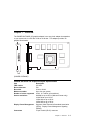
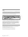
IBM POWER GXT2000P Graphics Adapter Installation and User's Guide Note Before using this information and the product it supports, be sure to read the general information under "Product Warranties and Notices" included with your system unit. First Edition (March 1999) The following paragraph does not apply to the United Kingdom or any country where such provisions are inconsistent with local law: THIS PUBLICATION IS PROVIDED “AS IS” WITHOUT WARRANTY OF ANY KIND, EITHER EXPRESS OR IMPLIED, INCLUDING, BUT NOT LIMITED TO, THE IMPLIED WARRANTIES OF MERCHANTABILITY OR FITNESS FOR A PARTICULAR PURPOSE. Some states do not allow disclaimer of express or implied warranties in certain transactions, therefore, this statement may not apply to you. This publication could include technical inaccuracies or typographical errors. Changes are periodically made to the information herein; these changes will be incorporated in new editions of the publication. The manufacturer may make improvements and/or changes in the product(s) and/or the program(s) described in this publication at any time, without notice. It is possible that this publication may contain reference to, or information about, products (machines and programs), programming, or services that are not announced in your country. Such references or information must not be construed to mean that these products, programming, or services will be announced in your country. Any reference to a specific licensed program in this publication is not intended to state or imply that you can use only that licensed program. You can use any functionally equivalent program instead. Requests for technical information about products should be made to your authorized reseller or marketing representative. International Business Machines Corporation 1999. All rights reserved. Note to U.S. Government Users -- Documentation related to restricted rights -- Use, duplication or disclosure is subject to restrictions set forth is GSA ADP Schedule Contract with IBM Corp. Contents Safety Information . . . . . . . . . . . . . . . . . . . . . . . . . . . . . . . . . . . . . . . . . . . . . . . . . . . . . . . . . . . . . . . . vii . . . . . . . . . . . . . . . . . . . . . . . . . . . . . . . . . . . . . ix ix ix ix Handling Static Sensitive Devices About This Book . ISO 9000 . . . . . . Related Publications Trademarks . . . . v . . . . . . . . . . . . . . . . . . . . . . . . . . . . . . . . . . . . . . . . . . . . . . . . . . . . . . . . . . . . . . . . . . . . . . . . . . . . . . . . . . . . . . . . . . . . . . . . . . . . . . . . . . . . . . Chapter 1. Overview . . . . . . . . . . . . . . . . . . . . POWER GXT2000P 3D Graphics Adapter Specifications Software Requirements . . . . . . . . . . . . . . . . . . . . Chapter 2. Preparing for Installation Inventory . . . . . . . . . . . . . . . . . . . . . . . . . . . . . . . . . . . . . . . . . . . . . . . . . . . . . . . . . . . . . . . . . . . . . . . . . . . . . . . . . . . . . . . . . . . . . . Chapter 3. Installing Device Driver Software Device Driver Software Installation . . . . . . . Chapter 4. Installing Hardware Installing the Adapter . . . . . . . Troubleshooting . . . . . . . . . . . . . . . . . . . . . . . . . . . . . . . . . . . . . . . . . . . . . . . . . . . . . . . . . . . . . . . . . . . . . . . . . . . . . . . . . . . . . . . . . . . . . . . . . . . . . . . . . . . . . . . . . . . . . . . . . . . . . . . . . . . . . . . . . . . . . . . . . . . Chapter 5. Display Information . . . Display Power Management . . . . . . Change Resolution and Refresh Rates . . . . . . . . . . . . . . . . . . . . . . . . . . . . . . . . . . . . . . . . . . . . . . . . . . . . . . . . . . . . . . . . . . . . . . . . . . . Chapter 6. Software Application Considerations Starting the Server in Overlay and Color Planes . . API Required Parameters . . . . . . . . . . . . . . . . . . . . . . . . . . . . . . . . . . . . . . . . . . . . . . . . . . . . . . . . . . . . . . . . . . Appendix A. Communications Statements . . . . . . . . . . . . . . . . . . . Federal Communications Commission (FCC) Statement . . . . . . . . . . . . European Union (EU) Statement . . . . . . . . . . . . . . . . . . . . . . . . . . International Electrotechnical Commission (IEC) Statement . . . . . . . . . . . United Kingdom Telecommunications Safety Requirements . . . . . . . . . . . Avis de conformité aux normes du ministère des Communications du Canada Canadian Department of Communications Compliance Statement . . . . . . . VCCI Statement . . . . . . . . . . . . . . . . . . . . . . . . . . . . . . . . . . . . Radio Protection for Germany . . . . . . . . . . . . . . . . . . . . . . . . . . . . 1-1 1-1 1-2 2-1 2-1 3-1 3-1 4-1 4-1 4-2 5-1 5-1 5-1 6-1 6-1 6-1 . . A-1 A-1 A-2 A-2 A-2 A-4 A-4 A-4 A-4 Contents iii . . . . . . . . . . . . . . . Reader's Comments — We'd Like to Hear From You iv Installation and User's Guide . . . . . . . . . . . . . . . X-1 Safety Information DANGER An electrical outlet that is not correctly wired could place hazardous voltage on metal parts of the system or the devices that attach to the system. It is the responsibility of the customer to ensure that the outlet is correctly wired and grounded to prevent an electrical shock. Before installing or removing signal cables, ensure that the power cables for the system unit and all attached devices are unplugged. When adding or removing any additional devices to or from the system, ensure that the power cables for those devices are unplugged before the signal cables are connected. If possible, disconnect all power cables from the existing system before you add a device. Use one hand, when possible, to connect or disconnect signal cables to prevent a possible shock from touching two surfaces with different electrical potentials. During an electrical storm, do not connect cables for display stations, printers, telephones, or station protectors for communication lines. Safety Information v vi Installation and User's Guide Handling Static Sensitive Devices Attention: Static electricity can damage this device and your system unit. To avoid damage, keep this device in its static protective bag until you are ready to install it. To reduce the possibility of electrostatic discharge, follow the precautions listed below: Limit your movement. Movement can cause static electricity to build up around you. Handle the device carefully, holding it by its edges or its frame. Do not touch solder joints, pins, or exposed printed circuitry. Do not leave the device where others can handle and possibly damage the device. While the device is still in its anti-static package, touch it to an unpainted metal part of the system unit for at least two seconds. (This drains static electricity from the package and from your body.) Remove the device from its package and install it directly into your system unit without setting it down. If it is necessary to set the device down, place it on its static-protective package. (If your device is an adapter, place it component-side up.) Do not place the device on your system unit cover or on a metal table. Take additional care when handling devices during cold weather, as heating reduces indoor humidity and increases static electricity. Preface vii viii Installation and User's Guide About This Book Use this book with your system unit documentation to install the POWER GXT2000P graphics adapter and its associated device driver software. ISO 9000 ISO 9000 registered quality systems were used in the development and manufacturing of this product. Related Publications This book refers to the documentation that came with your system unit and with your operating system. Additional references are made to adapter (slot) placement documentation. Trademarks CATIA is a registered trademark of Dassault Systems. graPHIGS is a trademark of International Business Machines. GL is a trademark of Silicon Graphics, Incorporated. OpenGL is a trademark of Silicon Graphics, Incorporated. PowerPC is trademark of International Business Machines Corporation. POWER GXT2000P is a registered trademark of International Business Machines. X Window System is a trademark of Massachusetts Institute of Technology. AIX is a registered trademark of International Business Machines. About This Book ix x Installation and User's Guide Chapter 1. Overview The POWER GXT2000P 3D graphics adapter is an entry level adapter that attaches to your system unit in a PCI bus 32-bit or 64-bit slot. This adapter provides 3D graphics acceleration. Fan (POWER GXT2000P) POWER GXT2000P 3D Graphics Adapter Specifications Item FRU number Bus architecture Bus width Maximum number Number of colors supported Screen resolutions Display Power Management Connectors Description 07L7495 PCI 32-bit or 64-bit Up to four per system 24-bit, 16.7 million (all resolutions) 640x480 at up to 85 Hz (Welcome Center only) 1024x768 at up to 85 Hz 1280x1024 at up to 85 Hz 1600x1200 at up to 85 Hz 1900x1200 at up to 76 Hz Supports Video Electronics Standards Association (VESA). Display Power Management Signaling (DPMS). 15-pin D-shell (HD-15) connector Chapter 1. Overview 1-1 The POWER GXT2000P Adapter Supports: 8-, 16-, or 24-bit double-buffered color 8-bit stored alpha 4-bit double-buffered overlay or 8-bit single-buffered overlay 32MB unified frame buffer 4 bits of window ids 24-bit z-buffer 8-bit stencil/clip OpenGL, graPHIGS, and APIs Trilinear Texture Mapping – 16MB Texture Memory at 1280x1024 Separate Gamma Correction Table Video Support – Point Sampling and Bilinear Scaling – Color Space Conversion Sissor Registers 3D Acceleration – Depth Buffering – Antialiasing – Gouraud Shading – Fog and Atmospheric effects – Stencil test – Alpha test – Blending – Dithering Software Requirements The POWER GXT2000P is supported on AIX 4.2.1 or 4.3.2 or later. OpenGL requires OpenGLlevel 1.2 for AIX, version 4.3.2 Licensed Program Product (5696-939). graPHIGS requires the PHIGS for AIX, Version 4.3.2 Licensed Program Product (5696-907). If support is required on an AIX release other than AIX 4.2.1 or 4.3.2 and later, please ensure this adapter is supported on that release of AIX prior to install. Contact your support representative for assistance. 1-2 Installation and User's Guide Chapter 2. Preparing for Installation This section outlines the installation procedure for the POWER GXT2000P device driver and graphics adapter. The process includes: An inventory of installation materials. The installation of your device driver software. Note: If AIX is not installed on your system unit, install your graphics adapter before you install the operating system. (See Chapter 4, “Installing Hardware” on page 4-1.) Then, when you install AIX 4.2.1 or later, your device driver software installs automatically. If AIX is operating on your system, install your device driver software prior to installing your graphics adapter. (See Chapter 3, “Installing Device Driver Software” on page 3-1.) The installation of your graphics adapter. Inventory To install the POWER GXT2000P, you need: The POWER GXT2000P adapter The system unit User's Guide The operating system documentation PCI Adapter Placement Reference A screw driver Media containing the device driver. Chapter 2. Preparing for Installation 2-1 2-2 Installation and User's Guide Chapter 3. Installing Device Driver Software This section explains how to install device driver software. Device Driver Software Installation 1. Be sure you have read Chapter 2, “Preparing for Installation” on page 2-1. Determine if you should install your device driver software first. Determine if you should install your graphics adapter hardware first. If you should install your device driver software first, go to step 2 and continue with this section. If you should install your hardware first, go to Chapter 4, “Installing Hardware” on page 4-1. When you install AIX, your device driver automatically installs. 2. Turn the system unit power on. 3. Log in as root. 4. Insert the media containing the device driver software (example: CD-ROM) into the appropriate media device. 5. Type the following smit devinst and press Enter. 6. The Install Additional Device Software screen highlights the "INPUT device/directory for software" option. 7. Select or type your input device: Press F4 to display the input device list. Select the name of the device (example: CD-ROM) that you are using and press Enter. -- or - In the Entry Field, type the name of the input device you are using and press Enter. 8. The Install Additional Device Software window highlights the SOFTWARE to install option. 9. Press F4 to display the SOFTWARE to install window. Chapter 3. Installing Device Driver Software 3-1 10. Type the following to display the Find window: / 11. Type the following devices.pci.141ðB8ðð and press Enter. (The system finds and highlights this device driver software.) 12. Press PF7 to select the highlighted device driver software and press Enter. Example: 4.3.2 devices.pci.141ðB8ðð 13. The Install Additional Device Software screen displays. Entry data fields are automatically updated. Press Enter to accept the data. 14. The ARE YOU SURE window displays. Press Enter to accept the data. 15. The COMMAND STATUS screen appears. The term RUNNING is highlighted to indicate that the install and configure command is in progress. When RUNNING changes to OK, scroll down to the bottom of the page and locate the Installation Summary. After a successful installation, SUCCESS appears in the Result column of the summary at the bottom of the page. 16. Remove the installation media from the drive. 17. Press F10 to exit SMIT. 18. Reference your system unit documentation to shutdown your system unit. 19. Go to graphics adapter install procedure, Chapter 4, “Installing Hardware” on page 4-1. 3-2 Installation and User's Guide Chapter 4. Installing Hardware This section provides the guidance necessary to install a graphics adapter. Before you begin, be sure you have read “Handling Static Sensitive Devices” on page vii. Attention: Do not remove the POWER GXT2000P from its anti-static package at this time. Installing the Adapter 1. Be sure you have read Chapter 2, “Preparing for Installation” on page 2-1. Determine if you should install your graphics adapter hardware first. Determine if you should install your device driver software first. If you should install your graphics adapter hardware first, go to 2 and continue with this section. If you should install your device driver software first, go back to Chapter 3, “Installing Device Driver Software” on page 3-1 and perform the procedures to install the device driver, then return here to install your hardware. 2. Refer to the User's Guide that shipped with your system unit to perform the following: Shutdown your system unit. – Refer to the PCI Adapter Placement Reference to identify supported installation slots for a POWER GXT2000P. Return here to complete the process. – Attention: Failure to install your graphics adapter in the correct slot may cause your adapter or system unit to function incorrectly. 3. Install the graphics adapter into your system unit. 4. After the installation of the adapter is complete, connect your keyboard and mouse to the system unit and connect your video cable to the graphics adapter. Note: If you are installing your adapter in a new system and AIX has not been installed go to 5. If you are installing your adapter in an existing system with AIX installed, go to step 6 on page 4-2 5. Install the AIX operating system on your system. Follow the documentation that came with the operating system to install AIX. Chapter 4. Installing Hardware 4-1 6. Turn on both your system unit and your display. Follow any instructions on the screen. 7. A select display (console) icon appears on your screen. Press the number key (for example, 1 or 2) on your keyboard of the monitor you want to be your default display. Note: If you are planning to run applications such as OpenGL or graPHIGS be sure to install the appropriate level LPP after you install the POWER GXT2000P Adapter. Troubleshooting Initial installation problems are often resolved using a few basic troubleshooting steps: Check Cables Check Installed Software (lslpp) Check Console (possibly redirect) Check Installed Hardware (lsdev) Check Cables 1. Ensure your cables are connected to the correct adapter. If you have more than one display adapter, be sure that each adapter is connected to a display. Verify the cable connection to your video monitor is made through a high density 15 pin D-shell connector. (For detailed connector information, go to Adapters, Devices, and Cable Information for Multiple Bus Systems if you received this book with your system unit.) 2. If no login prompt appears, reset the system to what it was before the adapter was added. Restart your system unit. 3. If the system responds with a login prompt, continue with the troubleshooting verifications. 4-2 Installation and User's Guide Verify Software Installation 1. Verify the device driver for the POWER GXT2000P is installed. Login as root Type: lslpp -l all | grep POWER GXT2ðððP and press Enter. 2. If the POWER GXT2000P device driver is installed, the following is an example of the data that appears if you are running AIX Version 4.3.2. devices.pci.141ðB8ðð.X11 4.3.2 COMMITTED AIXwindows GXT2ðððP Graphics devices.pci.141ðB8ðð.diag 4.3.2 COMMITTED GXT2ðððP Graphics Adapter devices.pci.141ðB8ðð.rte 4.3.2 COMMITTED GXT2ðððP Graphics Adapter Note: If you are running AIX 4.2.1, 4.3.2 in the examples above are replaced by 4.2.1. 3. If the POWER GXT2000P device driver did not install, return to Chapter 3, “Installing Device Driver Software” on page 3-1. Check Console 1. If you continue to experience problems, it may be necessary to redirect the device console to the new adapter using the chdisp command. Refer to your operating system documentation for directions. 2. If you have checked your cables, tried the chdisp command and continue to experience problems, run diagnostics. Refer to your operating system documentation for directions. Chapter 4. Installing Hardware 4-3 Verify Hardware Installation 1. To verify your system unit recognizes the POWER GXT2000P adapter: Type: lsdev -Cs pci and press Enter. 2. If the POWER GXT2000P adapter did install, the following is an example of the data that appears on your screen: mirð Available ð4-ð2 GXT2ðððP. Graphics Adapter 3. If the message on your screen indicates your adapter is Defined instead of Available, shut down your machine. Check the POWER GXT2000P adapter to insure it is installed correctly. 4. If the POWER GXT2000P adapter did not install, return to Chapter 4, “Installing Hardware” on page 4-1. If you continue to experience problems, it may be necessary to call your system support organization. Refer to your operating system documentation for directions. 4-4 Installation and User's Guide Chapter 5. Display Information Display Power Management The POWER GXT2000P graphics adapter supports Video Electronics Standards Association (VESA), Display Power Management Signalling (DPMS). Change Resolution and Refresh Rates To change the resolution and refresh rates for X Windows or Common Desktop Environment (CDE) sessions, complete the following steps: 1. Turn your system unit power on. 2. Log in as root 3. Type the following smit and press Enter. 4. From the System Management screen, select Devices and press Enter. 5. Select Graphic Displays and press Enter. 6. Select Select the Display Type. 7. Select the GXT2000P Graphics Adapter and press Enter. 8. Press PF4 for a list of Display Types supported. 9. Select the desired type and press Enter. Note: If POWER GXT2000P detects a Data Display Channel (DDC) monitor, "default" is your only SMIT screen option. For DDC monitor owners, pressing PF4 here creates an information message that states the popup is not available for this entry field. Press PF3. This brings you back to the Graphics Display screen. Go to step 12 to resume the procedure as a DDC monitor owner. 10. In the select the Display Type screen, notice the Select Display Type Field data has been updated. Press Enter. 11. Press PF3 twice to return to the Graphics Display Screen. 12. Select Select the Display Resolution and Refresh Rate and press Enter. 13. From the Graphics Adapter screen, select the GXT2000P Graphics Adapter and press Enter. 14. Press PF4 for a list of Resolution and Refresh Rates that are supported. Chapter 5. Display Information 5-1 15. Select the desired rate and press Enter. Note: Your X session or CDE session runs at the rate specified the next time you bring up one of these sessions. 16. Press F10 to exit SMIT. 5-2 Installation and User's Guide Chapter 6. Software Application Considerations This chapter discusses operating system tasks related to the POWER GXT2000P graphics adapter. Starting the Server in Overlay and Color Planes The X Windows server can create windows in a separate set of frame buffer planes called overlays. The X Windows server supports this by defining distinct visuals for the overlay and color planes. The -layer n parameter for xinit gives the system the ability to select the hardware frame buffer planes in which to run the X Windows server. A value of: 0 indicates the color plane. 1 indicates the overlay plane (default). These are the only valid choices. All other choices default to layer 1. Starting the X Windows server in the color planes xinit -- -layer ð <other flags> Starting the X Windows server in the overlay planes xinit -- -layer 1 <other flags> or xinit -- <other flags> Refer to your operating system documentation for descriptions “other flags” as needed. API Required Parameters Following are xinit options that take advantage of 3D hardware capabilities. These options are required to run the 3D application programming interfaces (APIs). API for OpenGL: Starting the X Windows server for the OpenGL API requires the following parameter: -x GLX. For example: xinit -- -x dbe -x abx -x GLX <other flags> Chapter 6. Software Application Considerations 6-1 API for graPHIGS: Using the visual associated with the window, graPHIGS supports creating gP windows as 8-bit Indexed, 24-bit TrueColor, or 24-bit DirectColor. Additionally, the gP window must be created in the color planes and for the best performance, it is recommended that the X Windows window (root window when the X Windows server is started) be created in the overlay planes. In support of echoes, graPHIGS on behalf of the application creates a child window in the overlay planes. The gP window: May be created by the application. The application passes the window id to graPHIGS via the XWINDID procopt -- or - May be created by graPHIGS on behalf of the application when the workstation is created. At its creation, the visual associated with the gP window is selected as follows: A visual may be specifically selected by the application from the supported visuals for the color planes via the XGetVisualInfo function and passed to the XCreateWindow function to create the gP window in the color planes. In this case, start the X Windows server in the overlay planes as follows: xinit -- -x dbe -x abx and within your application, select the desired visual and pass it to the XCreateWindow function. This method produces optimum performance. The X Windows server starts in the overlay planes while the gP runs in the color planes. Windows in different planes do not cause expose events to each other, forcing redraws. If your application is not written to select a visual, you must alter your application to optimize performance. A sample program, windsamp, and a README are available to show how an application selects the desired visual and creates a gP window. You can locate this information in the /usr/lpp/graPHIGS/samples/windsamp directory. Your application may default to using the visual associated with the root window (the window created when the X Windows server was started) by not passing a selected visual to the XCreateWindow function. 6-2 Installation and User's Guide Start the X Windows server in the color planes and select one of the three graPHIGS supported visuals for the root window: Select the 8-bit visual: xinit -- -x dbe -x abx -layer ð Select the 24-bit DirectColor visual: xinit -- -x dbe -x abx -layer ð -d 24 -cc DirectColor Select the 24-bit TrueColor visual: xinit -- -x dbe -x abx -layer ð -d 24 -cc TrueColor This method requires no change to your application, but it does not give you the best performance. Since the X Windows server and graPHIGS are both running in the color planes, graPHIGS has to handle exposure events from manipulating the X Windows forcing more graPHIGS redraws. If the application chooses to create its own window and it is not the top level window, a Window Manager Install property must be added when creating the window. This property allows a color map to be installed for the graPHIGS child window in the overlays. This is created to support echoes. Chapter 6. Software Application Considerations 6-3 6-4 Installation and User's Guide Appendix A. Communications Statements The following statement applies to this product. The statement for other products intended for use with this product appears in their accompanying documentation. Federal Communications Commission (FCC) Statement Note: The POWER GXT2000P Graphics Adapter been tested and found to comply with the limits for a Class B digital device, pursuant to Part 15 of the FCC Rules. These limits are designed to provide reasonable protection against harmful interference in a residential installation. This equipment generates, uses, and can radiate radio frequency energy and, if not installed and used in accordance with the instructions, may cause harmful interference to radio communications. However, there is no guarantee that interference will not occur in a particular installation. If this equipment does cause harmful interference to radio or television reception, which can be determined by turning the equipment off and on, the user is encouraged to try to correct the interference by one or more of the following measures: Reorient or relocate the receiving antenna. Increase the separation between the equipment and receiver. Connect the equipment into an outlet on a circuit different from that to which the receiver is connected. Consult an authorized dealer or service representative for help. Properly shielded and grounded cables and connectors must be used in order to meet FCC emission limits. Proper cables and connectors are available from authorized dealers. Neither the provider nor the manufacturer are responsible for any radio or television interference caused by using other than recommended cables and connectors or by unauthorized changes or modifications to this equipment. Unauthorized changes or modifications could void the user's authority to operate the equipment. This device complies with Part 15 of the FCC Rules. Operation is subject to the following two conditions: (1) this device may not cause harmful interference, and (2) this device must accept any interference received, including interference that may cause undesired operation. Appendix A. Communications Statements A-1 Responsible Party: International Business Machines Corporation New Orchard Road Armonk, New York 10504 Telephone: (919) 543-2193 Tested to Comply With FCC Standards FOR HOME OR OFFICE USE European Union (EU) Statement This product is in conformity with the protection requirements of EU Council Directive 89/336/EEC on the approximation of the laws of the Member States relating to electromagnetic compatibility. The manufacturer cannot accept responsibility for any failure to satisfy the protection requirements resulting from a non-recommended modification of the product, including the fitting of option cards supplied by third parties. Consult with your dealer or sales representative for details on your specific hardware. This product has been tested and found to comply with the limits for Class B Information Technology Equipment according to CISPR 22 / European Standard EN 55022. The limits for Class B equipment were derived for typical residential environments to provide reasonable protection against interference with licensed communication devices. International Electrotechnical Commission (IEC) Statement This product has been designed and built to comply with IEC Standard 950. United Kingdom Telecommunications Safety Requirements This equipment is manufactured to the International Safety Standard EN60950 and as such is approved in the UK under the General Approval Number NS/G/1234/J/100003 for indirect connection to the public telecommunication network. The network adapter interfaces housed within this equipment are approved separately, each one having its own independent approval number. These interface adapters, supplied by the manufacturer, do not use or contain excessive voltages. An excessive voltage is one which exceeds 70.7 V peak ac or 120 V dc. They interface with this equipment using Safe Extra Low Voltages only. In order to A-2 Installation and User's Guide maintain the separate (independent) approval of the manufacturer's adapters, it is essential that other optional cards, not supplied by the manufacturer, do not use main voltages or any other excessive voltages. Seek advice from a competent engineer before installing other adapters not supplied by the manufacturer. Appendix A. Communications Statements A-3 Avis de conformité aux normes du ministère des Communications du Canada Cet appareil numérique de la classe B est conform à la norme NMB-003 du Canada. Canadian Department of Communications Compliance Statement This Class B digital apparatus complies with Canadian ICES-003. VCCI Statement The following is a summary of the VCCI Japanese statement in the box above. This product is a Class B Information Technology Equipment and conforms to the standards set by the Voluntary Control Council for Interference by Information Technology Equipment (VCCI). This product is aimed to be used in a domestic environment. When used near a radio or TV receiver, it may become the cause of radio interference. Read the instructions for correct handling. Radio Protection for Germany Dieses Gerät ist berechtigt in Übereinstimmung mit dem deutschen EMVG vom 9.Nov.92 das EG–Konformitätszeichen zu führen. Der Aussteller der Konformitätserklärung ist die IBM Germany. Dieses Gerät erfüllt die Bedingungen der EN 55022 Klasse B. A-4 Installation and User's Guide Reader's Comments — We'd Like to Hear From You POWER GXT2000P Graphics Adapter Installation and User's Guide Order Number: 41L5756 Overall how satisfied are you with the information in this book? Overall Satisfaction Very Satisfied Satisfied Neutral Ø Ø Ø Very Dissatisfied Dissatisfied Ø Ø How satisfied are you that the information in this book is: Accurate Complete Easy to find Easy to understand Well organized Applicable to your tasks Very Satisfied Satisfied Neutral Ø Ø Ø Ø Ø Ø Ø Ø Ø Ø Ø Ø Ø Ø Ø Ø Ø Ø Very Dissatisfied Dissatisfied Ø Ø Ø Ø Ø Ø Ø Ø Ø Ø Ø Ø Please tell us how we can improve this book: Thank you for your response. May we contact you? Ø Yes Ø No When you send comments to us, you grant us a nonexclusive right to use or distribute your comments in any way we believe appropriate without incurring any obligation to you. X-1 Cut or Fold Along Line Fold and Tape Please do not Staple Fold and Tape NO POSTAGE NECESSARY IF MAILED IN THE UNITED STATES BUSINESS REPLY MAIL POSTAGE WILL BE PAID BY ADDRESSEE Information Development Department H6DS-9561 11400 Burnet Road Austin, TX 78758-3493 Fold and Tape Please do not Staple Fold and Tape Cut or Fold Along Line X-2 Installation and User's Guide IBM Part Number: 41L5756 Printed in the United States of America on recycled paper containing 10% recovered post-consumer fiber. 41L5756


![HiSoft Devpac 3 (text version) [1992] [Manual: PDF]](http://vs1.manualzilla.com/store/data/005668901_1-67cf8256fc448cd2edf58a11a6ec729e-150x150.png)