1
IS220
OEM Scan Engine
User’s Guide
Disclaimer
Honeywell International Inc. (“HII”) reserves the right to make changes in specifications and other information
contained in this document without prior notice, and the reader should in all cases consult HII to determine
whether any such changes have been made. The information in this publication does not represent a
commitment on the part of HII.
HII shall not be liable for technical or editorial errors or omissions contained herein: nor for incidental or
consequential damages resulting from the furnishing, performance, or use of this manual.
This document contains propriety information that is protected by copyright. All rights reserved. No part of this
document may be photocopied, reproduced, or translated into another language without the prior written
consent of HII.
© 2004 - 2011 Honeywell International Inc. All rights reserved.
Web Address: www.honeywellaidc.com
Trademarks
Metrologic, MetroSelect, MetroSet2, are trademarks or registered trademarks of Metrologic Instruments, Inc. or
Honeywell International Inc.
Microsoft, Windows, and Windows 95 are trademarks or registered trademarks of Microsoft Corporation.
Other product names mentioned in this manual may be trademarks or registered trademarks of their respective
companies and are the property of their respective owners.
Patents
For patent information, please refer to www.honeywellaidc.com/patents.
Table of Contents
Introduction ..................................................................................................................................................... 1
Base Kit.......................................................................................................................................................... 1
Optional Accessories...................................................................................................................................... 1
Dimensions .................................................................................................................................................... 2
Maintenance................................................................................................................................................... 2
Scanner Components..................................................................................................................................... 3
Labels ............................................................................................................................................................ 4
Indicators
Audible Indicator ............................................................................................................................................ 5
Visual Indicator............................................................................................................................................... 6
Failure Indicators ............................................................................................................................................ 6
Diagnostic Indicator Display ........................................................................................................................... 7
Depth of Field .................................................................................................................................................. 9
Troubleshooting Guide ................................................................................................................................. 11
Design Specifications
Operational................................................................................................................................................... 15
Mechanical ................................................................................................................................................... 15
Electrical ...................................................................................................................................................... 15
Environmental .............................................................................................................................................. 16
Upgrading the Flash ROM Firmware ............................................................................................................ 17
Default Settings
Communication Parameters ......................................................................................................................... 19
Scanner and Cable Terminations
Scanner Pinout Connections ........................................................................................................................ 25
Cable Connector Configurations................................................................................................................... 25
Limited Warranty ........................................................................................................................................... 27
Laser and Product Safety
Cautions ....................................................................................................................................................... 29
Notices ......................................................................................................................................................... 30
Index ............................................................................................................................................................... 31
ii
Customer Support
Technical Assistance.................................................................................................................................... 33
Product Service and Repair .......................................................................................................................... 34
iii
Introduction
The IS220 is a dual optic bench scanning engine with scan lines optimized for orthogonal orientation of 1D bar
codes. IS220 is a completely self-contained scan engine.
Base Kit
Part Number
Description
IS220-16
IS220 OEM Engine ( RS232 )
00-02029
IS220 Installation and User’s Guide *
00-02407
MetroSelect Configuration Guide *
®
* Guides also available for download at www.honeywelladic.com.
Optional Accessories
Part Number
Description
52-52548
Communication/Power Cable 110 Volt
52-52547
Communication/Power Cable 220 Volt
Other items may be ordered for the specific protocol being used. To order additional items, contact the dealer,
distributor or call the customer service department.
1
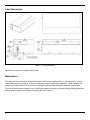
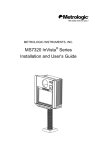
Case Dimensions
Figure 1. Case Dimensions
Specifications subject to change without notice.
Maintenance
Smudges and dirt on the unit’s window can interfere with the unit’s performance. If the horizontal or vertical
output windows require cleaning, use only a mild glass cleaner containing no ammonia. When cleaning the
window, spray the cleaner onto a lint free, non-abrasive cleaning cloth then gently wipe the window clean.
If the unit’s case requires cleaning, use a mild cleaning agent that does not contain strong oxidizing chemicals.
Strong cleaning agents may discolor or damage the unit’s exterior.
2
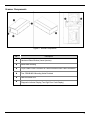
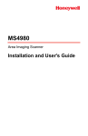
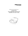
Scanner Components
Figure 2. Scanner Components
No.
Description
Hardened Glass Window (Laser Aperture)
Black Metal Housing
15-pin, Male D-Sub Connector for Communication/Power Cable Connection
Two, PEM B-M5-2 Mounting Holes Provided
Red and Green LED
Diagnostic Indicator Display (Two-Digit Error Code Display)
3
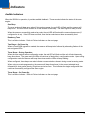
Labels
Figure 3. Label Locations and Examples
4
Indicators
Audible Indicators
When the IS220 is in operation, it provides audible feedback. These sounds indicate the status of the scan
engine.
One Beep
The scan engine will beep once when it first receives power, the red LED will flash and the scanner will
beep once. The red LED will remain on for the duration of the beep. The scan engine is ready to scan.
When the scanner successfully reads a bar code, the red LED will flash and the scanner beeps once (if
configured to do so). If the LED does not flash, then the bar code has not been successfully read.
Razzberry Tone
This is a failure indicator. Refer to Failure Indicators on the next page.
Two Beeps - On Power Up
When a Flash ROM upgrade is needed, the scanner will beep twice followed by alternating flashes of the
red and green LEDs.
Three Beeps - During Operation
When the scan engine enters configuration mode, the red LED will flash and the unit will simultaneously
beep three times. The green and red LEDs will continue to flash while in configuration mode. Upon exiting
configuration mode the scanner will beep three times and the LEDs will stop flashing.
When configured, three beeps can also indicate a communications timeout during normal scanning mode.
When using one-code programming, the scanner will beep three times (in the current selected tone),
followed by a short pause then by a high tone and a low tone. This indicates the single configuration bar
code has successfully configured the scan engine.
Three Beeps - On Power Up
This is a failure indicator. Refer to Failure Indicators on the next page.
5
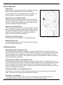
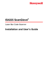
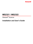
Visual Indicators
Steady Green
When the laser is active the green LED is illuminated. The green
LED will remain illuminated until the laser is deactivated.
During the power save mode, the laser will turn on and turn off.
During this period, the green LED will remain illuminated.
Steady Green and a Single Red Flash
When the scanner successfully reads a bar code, the red LED
will flash and the scanner will beep once. If the red LED does not
flash or the scanner does not beep once, then the bar code has
not been successfully read (default mode).
Steady Green and Steady Red
After a successful scan the scanner transmits the data to the host
device. Some communication modes require that the host inform
the scanner when data is ready to be received. If the host is not
ready to accept the information, the scanner’s red LED will
remain on until the data can be transmitted.
Steady Green and Flashing Red
This indicates that the scan engine is in configuration mode.
Figure 4. Green and Red LEDs
Steady Red, Green Off
This indicates that the laser is off and the scan engine is waiting
for communication from the host.
Failure Indicators
Flashing Green and One Razzberry Tone
This indicates that the scanner has experienced a laser subsystem failure. The scanner will try up to 3
times to correct the failure condition. If the laser subsystem continues to fail, that subsystem (left or right)
will be shut down and an error indication will be shown on the Diagnostic Indicator Display. This error
stays on the display until corrected. If the remaining subsystem is still operational, scanning will continue
using the operational components.
Flashing Green and Red and Two Razzberry Tones
This indicates that the scanner has experienced a motor subsystem failure. The scanner will try up to 3
times to correct the failure condition. If the motor subsystem continues to fail, that subsystem (left or right)
will be shut down and an error indication will be shown on the Diagnostic Indicator Display. This error
stays on the display until corrected. If the remaining subsystem is still operational, scanning will continue
using the still operational components.
Continuous Razzberry Tone with Both LEDs Off
If, upon power up, the scanner emits a continuous razzberry tone, then the scanner has an electronic
failure. Return the unit for repair at an authorized service center.
Three Beeps - On Power Up
If the scanner beeps 3 times on power up then, the nonvolatile memory that holds the scanner
configuration has failed. Return the unit for repair at an authorized service center.
6
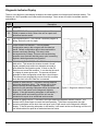
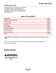
Diagnostic Indicator Display
There is a two-digit error code display located on the center printed circuit board (see illustration below). The
following is a list of possible error codes and their meanings. Some errors will require immediate scanner
maintenance.
Error
Code
Description
01
Reserved
02
RAM ERROR – The scanner’s Random Access Memory
(RAM) is tested as faulty. Return the unit for repair at an
authorized service center.
03
PROGRAM ERROR – The scanner’s software program is
failing. Return the unit for repair.
05
CONFIGURATION ERROR – The non-volatile
configuration memory did not agree with the data last
saved. Default configuration data is then used and the
scanner continues operating. This error is also
accompanied by 3 beeps. This error will remain during
operation as a reminder that this power cycle is scanning
against a default-generated configuration.
06
COMMUNICATION ERROR - The RS232 data line is being
held active. This causes the scanner to read a “break”
signal constantly and continuous attempts are made to
enter MetroSet configuration mode. A short on the RX
Data line can cause this condition. It can also be the result
of a laptop in power save mode. The scanner will abort
attempts to enter configuration mode after a short timeout.
The scanner can automatically recover from this condition
once the short in the RX Data line is corrected.
21
LASER #1 (left) ERROR – The laser in the left scanning
subsystem denotes a failure. The scanner will try three
times to correct the laser operation. If the laser error
persists, the left scanning subsystem will be shut down and
error code 21 will remain on the diagnostic indicator
display. If the right scanning subsystem is still healthy, it
will remain active and scanning until the unit can be
scheduled for repair at an authorized service center.
22
LASER #2 (right) ERROR – The laser in the right scanning subsystem denotes a failure. The
scanner will try three times to correct the laser operation. If the laser error persists, the right
scanning subsystem will be shut down and error code 22 will remain on the diagnostic indicator
display. If the left scanning subsystem is still healthy, it will remain active and scanning until the unit
can be scheduled for repair at an authorized service center.
Figure 5. Diagnostic Indicator Display
7
8
31
MOTOR #1 (left) ERROR – The motor in the left scanning subsystem denotes a failure. The
scanner will try three times to correct the motor operation. If the motor error persists, the left
scanning subsystem will be shut down and error code 31 will remain on the diagnostic indicator
display. If the right scanning subsystem is still healthy, it will remain active and scanning until the
unit can be scheduled for repair at an authorized service center.
32
MOTOR #2 (right) ERROR – The motor in the right scanning subsystem denotes a failure. The
scanner will try three times to correct the motor operation. If the motor error persists, the right
scanning subsystem will be shut down and error code 32 will remain on the diagnostic indicator
display. If the left scanning subsystem is still healthy, it will remain active and scanning until the unit
can be scheduled for repair at an authorized service center.
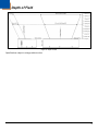
Depth of Field
Figure 6. Depth of Field
Specifications subject to change without notice.
9
10
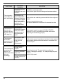
Troubleshooting Guide
The following guide is for reference purposes only. Contact a customer service representative to preserve the
limited warranty terms.
SYMPTOMS
POSSIBLE
CAUSE(S)
SOLUTION
No LEDs,
No beep or
No motor spin.
No power is being
supplied to the
scanner.
Check the transformer, outlet and power strip.
Make sure the cable is plugged into the scanner.
No LEDs,
No beep.
No power is being
supplied to the
scanner from host.
Some host systems cannot supply enough current to power an
IS220. Use the power supply included with the scanner.
The unit beeps
3 times on power
up.
There has been a
Non-volatile RAM
failure.
Contact a service representative if the unit will not hold the
programmed configuration.
The unit razzes
continuously on
power up.
There has been a
diagnostic failure.
Contact a service representative if the unit will not function.
At power up, there
is a Razz tone and
the green LED
flashes.
There has been a
VLD failure.
Contact a service representative.
At power up, there
is a Razz tone and
both LEDs flash.
There has been a
scanner motor
failure.
Contact a service representative.
There are multiple
scans upon
presentation of a
bar code.
The same symbol
timeout is set too
short.
Adjust the same symbol timeout for a longer time.
The unit powers
up, but does not
beep.
The beeper is
disabled.
Enable the beeper.
11
SYMPTOMS
POSSIBLE
CAUSE(S)
The unit is scanning
a particular
symbology that is not
enabled.
The unit powers
up, but does not
scan and/or beep.
The scanner has
been configured for a
character length lock,
or a minimum length
and the bar code
being scanned does
not satisfy the
configured criteria.
SOLUTION
UPC/EAN is enabled by default.
Verify that the type of bar code being read has been enabled.
Verify that the bar code being scanned falls into the configured
criteria.
Typical of Non-UPC/EAN codes.
The scanner defaults to a minimum of 4 character bar code.
The unit scans a
bar code, but
locks up after the
first scan (the red
LED stays on).
The scanner is
configured to support
some form of host
handshaking but is
not receiving the
signal.
If the scanner is setup to support ACK/NAK, RTS/CTS,
XON/XOFF or D/E, verify that the host cable and host are
supporting the handshaking properly.
The unit scans,
but the data
transmitted to the
host is incorrect.
The scanner’s data
format does not
match the host
system
requirements.
Verify that the scanner’s data format matches the host systems
requirements. Make sure that the scanner is connected to the
proper host port.
The unit beeps for
some bar codes
and NOT for
others of the same
bar code
symbology.
12
The print quality of
the bar code is
suspect.
Check the character
length lock.
The aspect ratio of
the bar code is out of
tolerance.
Check the print mode. The type of printer could be the
problem. Change print settings. For example change the print
mode to
econo or high speed.
SYMPTOMS
POSSIBLE
CAUSE(S)
SOLUTION
The bar code may
have been printed
incorrectly.
Check if it is a check digit/character/or border problem.
The scanner is not
configured correctly
for the type of bar
code.
Check if the check digits are set properly.
The minimum symbol
length setting does
not work with the bar
code.
Check if the correct minimum symbol length is set.
The unit is not
transmitting each
character.
The configuration is
not set correctly.
Increase the interscan code delay setting. Adjust if the F0
break is transmitted. It may be necessary to try this in both
settings.
Alpha characters
show as lower
case.
The computer is in
Caps Lock mode.
Enable the Caps Lock detect setting of the scanner to detect
whether the PC is operating in Caps Lock.
The unit beeps for
some bar codes
and NOT for
others of the same
bar code
symbology.
Com port at the host
is not working or
configured properly.
Power-up OK and
scans OK but
does not
communicate
properly to the
host.
Com port not
operating properly.
The host is receiving
data but the data
does not look
correct.
The scanner and
host may not be
configured for the
same interface font.
Check that the scanner and the host are configured for the
same interface font.
Characters are
being dropped.
Intercharacter delay
needs to be added to
the transmitted
output.
Add some intercharacter delay to the transmitted output by
using the MetroSelect Configuration Guide (MLPN 00-02407).
Check to make sure that the baud rate and parity of the
scanner and the communication port match and the program is
looking for “RS-232" data.
Cable is not
connected to the
proper com port.
13
14
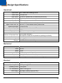
Design Specifications
Operational
Light Source: Two, Visible Laser Diodes @ 650 nm
Laser Power: 1 mW per VLD
Scan Pattern: 10 fields of 4 parallel lines (for ladder and picket fence)
Number of Scan Lines: 40
Scan Speed: 4000 scan lines per second +/- 5%
Depth of Scan Field, Near: 115 mm (4.5") from window surface, pattern offset
Depth of Scan Field, Far: 190 mm (7.5") from window surface, pattern offset
Minimum Bar Width: 0.2 mm (8.0 mil)
Decode Capability: Autodiscriminates all standard 1-D barcodes.
System Interface: RS232
Print Contrast: 35% minimum reflectance difference
Number of Characters Read:
Up to 80 data characters.
The maximum number will vary based on symbology and density.
Audible Indicators: Internal beeper
Visual Indicators (Default Green LED = Laser on, ready to scan
Settings): Red LED = Good read, decoding
Mechanical
Length: 295 mm
Width: 150 mm
Depth: 75 mm
Weight: 2.5 Kg maximum excluding cable
Termination: 15-pin, Male D-sub connector with screw locks
Mounting: Two, M5 tapped holes are provided for mounting purposes
Electrical
Input Voltage: 5VDC ± 0.25V
Operating Power: 6.25W typical @ 5VDC
Operating Current: 1.25A typical
DC Transformers: Class II; 5VDC @1.5A
Laser Class 2: IEC 60825-1:1993+A1:1997+A2:2001
EMC: FCC, ICES-003 & EN 55022 Class B
15
Environmental
Temperature:
Operating = 0°C to 40°C (32°F to 104°F)
Storage = -40°C to 60°C (-40°F to 140°F)
Humidity: 5% to 95% relative humidity , non-condensing
Contaminants: Sealed to resist airborne particulate contaminants
Ventilation: None required
Specifications subject to change without notice.
16
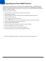
Upgrading the Flash ROM Firmware
The IS220 is part of Honeywell’s line of scanners with flash upgradeable firmware. The upgrade process
requires, a new firmware file supplied to the customer by a customer service representative and MetroSet2
software. A personal computer running Windows 95 or greater with an available RS232 serial or USB port is
required to complete the upgrade.
To upgrade the firmware in the IS220:
1. Plug the scanner into a serial communication port on the host system.
2. Start the MetroSet2 software.
3. Click on the plus sign (+) next to Industrial Scanners to expand the supported scanner list.
4. Choose the IS220 from the list.
5. Click on the Configure IS220 Scanner button.
6. Choose Utility, Flash Main Processor from the options list located on the left side of the screen.
7. Click on the Open File button in the Flash Utility window.
8. Locate and open the flash upgrade file.
9. Select the COM port that the scanner is connected to on the host system.
10. Verify the settings listed in the Flash Utility window.
11. Click on the Flash Scanner button to begin the flash upgrade.
12. A message will appear on the screen when the upgrade is complete.
MetroSet2 is available for download, at no additional cost, from www.honeywellaidc.com.
17
18
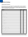
Default Settings
Communication Parameters
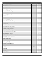
Many functions of the scanner can be "configured" - that is, enabled or disabled. The scanner is shipped from
the factory configured to a set of default conditions. The default parameter of the scanner has an asterisk ( * )
in the charts on the following pages. If an asterisk is not in the default column then the default setting is Off or
Disabled. Every interface does not support every parameter. If the interface supports a parameter listed in the
charts on the following pages, a check mark will appear.
Parameter
UPC/EAN
Code 128
Code 93
Codabar
Interleaved 2 of 5 (ITF)
MOD 10 Check on ITF
Code 11
Code 39
Full ASCII Code 39
MOD 43 CD on Code 39
Transmit Mode 43 CD
Paraff
Paraff Lead “A”
Allow Paraff Failures
French PC Terminal
MSI-Plessey
Airline (15 digit) 2 of 5
Airline (13 digit) 2 of 5
Matrix 2 of 5
Telepen
UK Plessey
STD 2 of 5
MSI-Plessey 10/10 Check Digit
MSI-Plessey MOD 10 Check Digit
ITF Symbol Lengths
ITF Minimum Symbol Length
Symbol Length Lock
Minimum Symbol Length
Trioptic
GS1 DataBar Enable
Default
RS232
*
Variable
6
None
4
19
Parameter
GS1 DataBar ID “]e0”
GS1 DataBar App ID “01”
GS1 DataBar Check Digit
GS1 DataBar Expanded Enable
Expanded ID “]e0”
GS1 DataBar Limited Enable
GS1 DataBar Limited ID “]e0”
GS1 DataBar Limited App ID “01”
GS1 DataBar Limited Check Digit
Beeper Tone
Beep Transmit Sequence
Beeper Volume
Communication Timeout
Razzberry Tone on Timeout
Three Beeps on Timeout
No Beeps on Timeout
Fast Beep
Beep Twice on Supplements
No Beeps on Timeout
5 Retries Before Timeout
Timeout In …
Laser Off Between Records
Variable Laser Off Delay
Flash LED on Good Scan
Reverse LED Convention
Flash LED on Good Scan
Enter Power Save Mode
Blink Power Save Mode
Default
*
*
*
*
*
*
*
Normal
Before
Transmit
Loudest
None
*
*
2 secs.
5 - 635 msec
*
*
10 mins.
*
Laser OFF Power Save Mode
Laser & Motor OFF Power Save Mode
Dual Action Power Save Mode #1
Dual Action Power Save Mode #2
Same Symbol Rescan Timeout: 500 msecs Programmable in 50 msec steps
(MAX 6.35 seconds)
Intercharacter Delay Programmable in 1 msec steps (MAX 255 msecs)
Number of Scan Buffers
UPC GTIN-14 Format
EAN-8 Enable
Transmit EAN-8 Check Digit
20
RS232
*
1 msecs
1
*
*
Parameter
Convert EAN-8 to EAN-13
EAN-13 Enable
Transmit EAN-13 Check Digit
UPC-A Enable
Convert UPC-A to EAN-13
Transmit UPC-A Check Digit
Transmit UPC-A Number System
Transmit UPC-A Manufacturers ID.
Transmit UPC-A Item ID
UPC-E Enable
Empand UPC-E
Transmit UPC-E Lead ‘0’
Transmit UPC-E Check Digit
Disable UPC-E Auto Redundancy
Default
*
*
*
*
*
*
*
*
*
*
RS232
Transmit Codabar Start/Stop Characters
Codabar CLSI
Dual Field Codabar
Tab Between Dual field Codabar
Codabar CLSI Check Digit
Codabar 7-Check Check Digit
Codabar Mod-16 Check Digit
Transmit MSI Plessey Check Digits
Number of MSI Plessey Check Digits
UK Plessey A to X Convert
UK Plessey Special 12 Character Format
Transmit UK Plessey Check Digit
EAN 128 Enable
Enable French Pharma
Enable Matrix 2 of 5 Check Digit
0
Enable Hong Kong 2 of 5
Enable Alpha Telepen
Telepen Convert Lead ‘^L’ to ‘E’
Enable Code 11 Check Digit
Parity
Baud Rate
8 Data Bits
7 Data Bits
Stop Bits
RTS / CTS Enabled
Space
19200
*
2
21
Parameter
Message RTS
Character RTS
ACK / NAK
O / N Handshaking
Host Bell / Cancel
Xon / Xoff
No Transmit Without DTR Present
French PC Terminal Emulation
“D/E” Disable Command
“Z/R” Disable Command
“F/L” Laser Command
“M/O” Motor Enable Commands
Beep on Bell
Razz on ‘z’
Activate on DTR
Activate on DC2 Character
Xmit No Read Message on DC2 Timeout
No Transmit LED During No Read Message
Programmable “No Read” Message
Recv “I” = Transmit “METROLOGIC”
Recv “i” = Transmit Scanner ID Byte
STX Prefix
TAB Prefix
Metrologic Prefix
UPC Prefix
ETX Suffix
TAB Suffix
Carriage Return Suffix
Line Feed Suffix
UPC Suffix
Default
*
*
*
*
RS232
Transmit LRC
Start LRC on 1st Byte
Start LRC on 2nd Byte
‘c’ Prefix for UPC
‘$’ Prefix for UPC
Programmable Prefix Characters
10 avail
Programmable Suffix Characters
10 avail
Multiple
Selections
Predefined Code ID Sets
22
Parameter
Default
Programmable Prefix for Code Types
Programmable Suffix for Code Types
Programmable Code Lengths
Code Selects
7 avail
7 avail
RS232
Code Select Timeout 0.1 to 25.5 seconds
5 sec
Replace 1 Character in Transmission
Razz on Code Select Timeout
Japan Dual Field Code Selects
*
EAN-13 Only in Japan Dual Field
Two Digit Supplements
Five Digit Supplements
Require Supplements
Remote Supplement Support
Two Digit Redundancy
Five Digit Redundancy
Enable Coupon Code 128
Transmit Coupon ‘]C1’
Group Separator
Coupon Code Can Begin with ’4’
Enable EAN-99 Coupon Code
Bookland
Convert Bookland to ISBN
Reformat ISBN
Transmit ISBN Check Digit
Bookland 977 2-Digit Supp Required
378 / 379 Supplements
*
*
414 / 419 Supplements
434 / 439 Supplements
Number System 2 Enables Supplements
Number System 5 Enables Supplements
100 msec to Find Supplement (100 - 800 msec)
Allow Code ID’s with Supplements
*
23
24
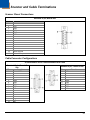
Scanner and Cable Terminations
Scanner Pinout Connections
Standard 15-pin, Male D-Sub
Pin
1
2
3
4
5
6
7
8
9
10
11
12
13
14
15
Function
Shield GND
TXD
RXD
DTR
GND
DSR
CTS
RTS
External LED
+5V
+5V
GND
GND
Earth Ground
External Beeper
Cable Connector Configurations
52-52548 and 52-52547 Communication/Power Cable
Standard 15-pin, Female DSub
Pin
Function
1
Shield GND
2
TXD
3
RXD
4
DTR
5
GND
6
DSR
7
CTS
8
RTS
9
N/C
10
+5V
11
+5V
12
GND
13
GND
14
Lug
15
N/C
Standard 9-pin, Female D-Sub
Pin
1
2
3
4
5
6
7
8
9
Function
N/C
TXD
RXD
DTR
GND
DSR
CTS
RTS
N/C
25
26
Limited Warranty
Honeywell International Inc. ("HII") warrants its products and optional accessories to be free from defects in
materials and workmanship and to conform to HII’s published specifications applicable to the products
purchased at the time of shipment. This warranty does not cover any HII product which is (i) improperly
installed or used; (ii) damaged by accident or negligence, including failure to follow the proper maintenance,
service, and cleaning schedule; or (iii) damaged as a result of (A) modification or alteration by the purchaser or
other party, (B) excessive voltage or current supplied to or drawn from the interface connections, (C) static
electricity or electro-static discharge, (D) operation under conditions beyond the specified operating
parameters, or (E) repair or service of the product by anyone other than HII or its authorized representatives.
This warranty shall extend from the time of shipment for the duration published by HII for the product at the
time of purchase ("Warranty Period"). Any defective product must be returned (at purchaser’s expense) during
the Warranty Period to HII factory or authorized service center for inspection. No product will be accepted by
HII without a Return Materials Authorization, which may be obtained by contacting HII. In the event that the
product is returned to HII or its authorized service center within the Warranty Period and HII determines to its
satisfaction that the product is defective due to defects in materials or workmanship, HII, at its sole option, will
either repair or replace the product without charge, except for return shipping to HII.
EXCEPT AS MAY BE OTHERWISE PROVIDED BY APPLICABLE LAW, THE FOREGOING WARRANTY IS
IN LIEU OF ALL OTHER COVENANTS OR WARRANTIES, EITHER EXPRESSED OR IMPLIED, ORAL OR
WRITTEN, INCLUDING, WITHOUT LIMITATION, ANY IMPLIED WARRANTIES OF MERCHANTABILITY OR
FITNESS FOR A PARTICULAR PURPOSE, OR NON-INFRINGEMENT.
HII’S RESPONSIBILITY AND PURCHASER’S EXCLUSIVE REMEDY UNDER THIS WARRANTY IS LIMITED
TO THE REPAIR OR REPLACEMENT OF THE DEFECTIVE PRODUCT WITH NEW OR REFURBISHED
PARTS. IN NO EVENT SHALL HII BE LIABLE FOR INDIRECT, INCIDENTAL, OR CONSEQUENTIAL
DAMAGES, AND, IN NO EVENT, SHALL ANY LIABILITY OF HII ARISING IN CONNECTION WITH ANY
PRODUCT SOLD HEREUNDER (WHETHER SUCH LIABILITY ARISES FROM A CLAIM BASED ON
CONTRACT, WARRANTY, TORT, OR OTHERWISE) EXCEED THE ACTUAL AMOUNT PAID TO HII FOR
THE PRODUCT. THESE LIMITATIONS ON LIABILITY SHALL REMAIN IN FULL FORCE AND EFFECT
EVEN WHEN HII MAY HAVE BEEN ADVISED OF THE POSSIBILITY OF SUCH INJURIES, LOSSES, OR
DAMAGES. SOME STATES, PROVINCES, OR COUNTRIES DO NOT ALLOW THE EXCLUSION OR
LIMITATIONS OF INCIDENTAL OR CONSEQUENTIAL DAMAGES, SO THE ABOVE LIMITATION OR
EXCLUSION MAY NOT APPLY TO YOU.
All provisions of this Limited Warranty are separate and severable, which means that if any provision is held
invalid and unenforceable, such determination shall not affect the validity of enforceability of the other
provisions hereof. Use of any peripherals not provided by the manufacturer may result in damage not covered
by this warranty. This includes but is not limited to: cables, power supplies, cradles, and docking stations. HII
extends these warranties only to the first end-users of the products. These warranties are non-transferable.
The duration of the limited warranty for the IS220 is two (2) year(s). The accessories have a 90 day limited
warranty from the date of manufacture.
27
28
Laser and Product Safety
Cautions
Caution
Use of controls or adjustments or performance of procedures other than those specified herein may result
in hazardous laser light exposure. Under no circumstances should the customer attempt to service the
laser scanner. Never attempt to look at the laser beam, even if the scanner appears to be nonfunctional.
Never open the scanner in an attempt to look into the device. Doing so could result in hazardous laser light
exposure. The use of optical instruments with the laser equipment will increase eye hazard.
Atención
La modificación de los procedimientos, o la utilización de controles o ajustes distintos de los especificados
aquí, pueden provocar una luz de láser peligrosa. Bajo ninguna circunstancia el usuario deberá realizar el
mantenimiento del láser del escáner. Ni intentar mirar al haz del láser incluso cuando este no esté
operativo. Tampoco deberá abrir el escáner para examinar el aparato. El hacerlo puede conllevar una
exposición peligrosa a la luz de láser. El uso de instrumentos ópticos con el equipo láser puede
incrementar el riesgo para la vista.
Attention
L'emploi de commandes, réglages ou procédés autres que ceux décrits ici peut entraîner de graves
irradiations. Le client ne doit en aucun cas essayer d'entretenir lui-même le scanner ou le laser. Ne
regardez jamais directement le rayon laser, même si vous croyez que le scanner est inactif. N'ouvrez
jamais le scanner pour regarder dans l'appareil. Ce faisant, vous vous exposez à une rayonnement laser
qú êst hazardous. L'emploi d'appareils optiques avec cet équipement laser augmente le risque
d'endommagement de la vision.
Achtung
Die Verwendung anderer als der hier beschriebenen Steuerungen, Einstellungen oder Verfahren kann eine
gefährliche Laserstrahlung hervorrufen. Der Kunde sollte unter keinen Umständen versuchen, den LaserScanner selbst zu warten. Sehen Sie niemals in den Laserstrahl, selbst wenn Sie glauben, daß der
Scanner nicht aktiv ist. Öffnen Sie niemals den Scanner, um in das Gerät hineinzusehen. Wenn Sie dies
tun, können Sie sich einer gefährlichen Laserstrahlung aussetzen. Der Einsatz optischer Geräte mit dieser
Laserausrüstung erhöht das Risiko einer Sehschädigung.
Attenzione
L’utilizzo di sistemi di controllo, di regolazioni o di procedimenti diversi da quelli descritti nel presente
Manuale può provocare delle esposizioni a raggi laser rischiose. Il cliente non deve assolutamente tentare
di riparare egli stesso lo scanner laser. Non guardate mai il raggio laser, anche se credete che lo scanner
non sia attivo. Non aprite mai lo scanner per guardare dentro l’apparecchio. Facendolo potete esporVi ad
una esposizione laser rischiosa. L’uso di apparecchi ottici, equipaggiati con raggi laser, aumenta il rischio
di danni alla vista.
Class 2 Laser Product
Laser Klasse 2 Produkt
Appareil A Laser De Classe 2
29
Notices
This device complies with Part 15 of the FCC Rules. Operation is subject to the following two conditions: (1)
This device may not cause harmful interference, and (2) this device must accept any interference received,
including interference that may cause undesired operation.
This equipment has been tested and found to comply with the limits for a Class B digital device, pursuant to
Part 15 of the FCC rules. These limits are designed to provide reasonable protection against harmful
interference in a residential installation. This equipment generates, uses and can radiate radio frequency
energy and, if not installed and used in accordance with the instructions, may cause harmful interference to
radio communications. However, there is no guarantee that interference will not occur in a particular
installation. If this equipment does cause harmful interference to radio or television reception, which can be
determined by turning the equipment off and on, the user is encouraged to try to correct the interference by
one or more of the following measures:
•
•
•
•
Reorient or relocate the receiving antenna
Increase the separation between the equipment and receiver
Connect the equipment into an outlet on a circuit different from that to which the receiver is connected
Consult the dealer or an experienced radio/TV technician for help
Notice
This Class B digital apparatus complies with Canadian ICES-003.
Avertissement
Cet appareil numérique de la class B est conforme à la norme NMB-003.
30
Index
A
Accessories ........................................................... 1
Application ............................................................. 7
Audible Indicators .......................................... 11–13
B
Beeper....................................................... 5, 19–23
C
Cable
Communication......................................... 1, 3, 25
Configuration .................................................... 25
Pinouts ............................................................. 25
Power ....................................................... 1, 3, 25
Troubleshooting .......................................... 11–13
Case
Components ....................................................... 3
Dimensions ......................................................... 2
Caution ............................................................ 4, 29
CE ....................................................................... 29
Communication
Default Settings .......................................... 19–23
Troubleshooting .......................................... 11–13
compliance .......................................................... 27
Configuration ............................................. 7, 11–13
Guide ............................................................ 1, 13
customer service ................................................. 27
Customer Service .................................................. 1
Ground ................................................................ 25
H
Host .............................................................. 19–23
I
Indicators
Audible ....................................... 5, 11–13, 19–23
Error Codes .................................................... 3, 7
Failure ............................................................ 3, 5
Visual ......................................3, 5, 11–13, 19–23
L
Label
Caution ............................................................... 4
Location ............................................................. 4
Serial Number .................................................... 4
Laser Aperture ................................................ 3, 10
Laser Class ......................................................... 15
Laser Light .................................................. 4, 7, 29
M
Maintenance ................................................... 7, 10
Meteor ................................................................. 17
MetroSet2 ........................................................... 17
Mounting Holes ................................................. 2, 3
N
Notices ................................................................ 29
D
P
Default Settings ............................................. 19–23
Depth of Field
Far .................................................................... 10
Near ................................................................. 10
Diagnostic Indicator Display .............................. 3, 7
Parameters ................................................... 19–23
PC ................................................................. 19, 22
Product
Safety ............................................................... 29
E
EMC .................................................................... 15
Error Codes ....................................................... 3, 7
F
Failure Modes ........................................................ 5
FCC ..................................................................... 29
Flash ROM Firmware .......................................... 17
G
R
Red LED ........................................................... 3, 5
repair ................................................................... 27
Repair ................................................................... 7
RMA .................................................................... 27
RS232 ........................................................... 19–23
S
Scanner
Pinouts ............................................................. 25
service................................................................. 27
Green LED ........................................................ 3, 5
31
Specifications
Electrical ........................................................... 15
Environmental................................................... 15
Mechanical ....................................................... 15
Operational ....................................................... 15
Symbol Length .............................................. 11–13
T
Troubleshooting ............................................. 11–13
U
Upgrade .............................................................. 17
32
V
Visual Indicator
Green LED ..............................3, 5, 11–13, 19–23
Red LED .................................3, 5, 11–13, 19–23
W
warranty .............................................................. 27
Window ....................................................... 3, 7, 10
Customer Support
Technical Assistance
If you need assistance installing or troubleshooting your device, please call your distributor or the nearest
technical support office:
North America/Canada
Telephone: (800) 782-4263
E-mail: [email protected]
Latin America
Telephone: (803) 835-8000
Telephone: (800) 782-4263
E-mail: [email protected]
Brazil
Telephone: +55 (21) 3535-9100
Fax: +55 (21) 3535-9105
E-mail: [email protected]
Mexico
Telephone: 01-800-HONEYWELL (01-800-466-3993)
E-mail: [email protected]
Europe, Middle East, and Africa
Telephone: +31 (0) 40 7999 393
Fax: +31 (0) 40 2425 672
E-mail: [email protected]
Hong Kong
Telephone: +852-29536436
Fax: +851-2511-3557
E-mail: [email protected]
Singapore
Telephone: +65-6842-7155
Fax: +65-6842-7166
E-mail: [email protected]
China
Telephone: +86 800 828 2803
Fax: +86-512-6762-2560
E-mail: [email protected]
Japan
Telephone: +81-3-6730-7344
Fax: +81-3-6730-7222
E-mail: [email protected]
Online Technical Assistance
You can also access technical assistance online at www.honeywellaidc.com.
33
Product Service and Repair
Honeywell International Inc. provides service for all its products through service centers throughout the world.
To obtain warranty or non-warranty service, contact the appropriate location below to obtain a Return Material
Authorization number (RMA #) before returning the product.
North America
Telephone: (800) 782-4263
E-mail: [email protected]
Latin America
Telephone: (803) 835-8000
Telephone: (800) 782-4263
Fax: (239) 263-9689
E-mail: [email protected]
Brazil
Telephone: +55 (21) 3535-9100
Fax: +55 (21) 3535-9105
E-mail: [email protected]
Mexico
Telephone: 01-800-HONEYWELL (01-800-466-3993)
Fax: +52 (55) 5531-3672
E-mail: [email protected]
Europe, Middle East, and Africa
Telephone: +31 (0) 40 2901 633
Fax: +31 (0) 40 2901 631
E-mail: [email protected]
Hong Kong
Telephone: +852-29536436
Fax: +851-2511-3557
E-mail: [email protected]
Singapore
Telephone: +65-6842-7155
Fax: +65-6842-7166
E-mail: [email protected]
China
Telephone: +86 800 828 2803
Fax: +86-512-6762-2560
E-mail: [email protected]
Japan
Telephone: +81-3-6730-7344
Fax: +81-3-6730-7222
E-mail: [email protected]
Online Product Service and Repair Assistance
You can also access product service and repair assistance online at www.honeywellaidc.com.
34
Honeywell Scanning & Mobility
9680 Old Bailes Road
Fort Mill, SC 29707
www.honeywellaidc.com
00-02029 Rev C
5/11