1
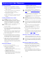
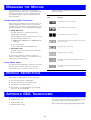
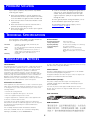
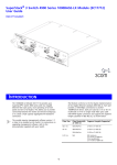
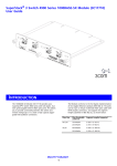
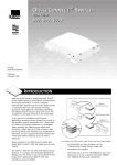
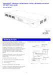
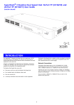
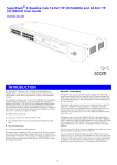
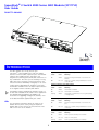
SuperStack® 3 Switch 4900 Series GBIC Module (3C17714) User Guide DUA1771-4AAA01 INTRODUCTION The GBIC Module (3C17714) provides your SuperStack® 3 Switch 4900 Series with four Gigabit Interface Convertor (GBIC) expansion ports. The Module supports fiber Gigabit Ethernet short-wave (SX), long-wave (LX) and long-haul (LH70) GBIC transceivers in any combination. This offers you the flexibility of using GBIC transceivers to provide connectivity between the Switch and remote 1000 Mbps workgroups or to create a high capacity aggregated link backbone connection. The Module conforms to the full duplex implementation of the Gigabit Ethernet standard, IEEE 802.3x. Expansion Module Activity LED (Switch) Status Color Meaning On Amber Packets are being transmitted or received on the Module. Off No color There are no packets being transmitted or received on the Module. Expansion Module Status LED (Switch) The Module requires management software version 1.3 or later to be installed on the Switch. This is supplied on the CD-ROM that accompanies the Module. For instructions on upgrading management software, refer to the documentation supplied with your Switch. Status Color Meaning On Amber The Module is installed. Off No color The Module is not installed. Flashing Amber The Module is installed but is not recognised (faulty or unsupported). Port Activity LED (Module) LEDs You can gather information about the status of the Module and its packet activity using the Expansion Module LEDs on the front of the Switch and the Port LEDs on the front of the Module. Status Color Meaning On Amber Packets are being transmitted or received on this port. Off No color There are no packets being transmitted or received on this port. Port Status LED (Module) 1 Status Color Meaning On Green A link is present and the port is enabled. Off No color There is no link present. Flashing Green A link is present and the port is disabled. INSTALLATION AND REMOVAL ! WARNING: Installation and removal of the Module must be carried out by qualified personnel only. Before installing the Module into a unit, you must first disconnect the unit from the mains power supply. For full safety instructions, refer to the user guide that accompanies the unit. WARNING: Fiber Optic ports - Optical Safety ! AVERTISSEMENT: Confiez l'installation et la dépose de ce Module à un personnel qualifié. Avant d'installer ce Module dans un groupe, vous devez au préalable débrancher ce groupe de l'alimentation secteur. Pour prendre connaissance des consignes complètes de sécurité, consultez le guide utilisateur qui accompagne ce groupe. Never look at the transmit laser while it is powered-up. Never look directly at the fiber TX port and fiber cable ends when they are powered-up. ! ACHTUNG: Die Installation und der Ausbau des Moduls darf nur durch Fachpersonal erfolgen. Vor dem Installieren des Moduls in einem Gerät muß zuerst der Netzstecker des Geräts abgezogen werden. Vollständige Sicherheitsanweisungen sind dem Benutzerhandbuch des Geräts zu entnehmen. ! WARNING: When the Module is inserted into the switch, the three captive thumbscrews securing the Module must be tightened with a suitable tool. Keep the blanking plate and the fixings in a safe place. If you remove the Module at any time, you must then replace the blanking plate. WARNING: Use of controls or adjustments of performance or procedures other than those specified herein may result in hazardous laser emissions. AVERTISSEMENT: Ports pour fibres optiques – sécurité sur le plan optique Ne regardez jamais le laser tant qu'il est sous tension. Ne regardez jamais directement le port TX (Transmission) à fibres optiques et les embouts de câbles à fibres optiques tant qu'ils sont sous tension. AVERTISSEMENT: Quand le Module est introduit dans le commutateur, il faut visser les trois vis moletées imperdables, qui bloquent le Module, avec un outil adapté. Conservez la plaque d'obturation et les fixations en lieu sûr. Si vous retirez le Module à tout instant, vous devez alors replacer la plaque d'obturation. ! ACHTUNG: Beim Einsetzen des Moduls in dem Switch sind die drei unverlierbaren Flügelschrauben mit einem passenden Werkzeug festzuziehen. Die Distanzplatte und die Befestigungselemente an einem sicheren Ort aufbewahren. Beim Austausch des Moduls ist auch die Distanzplatte zu ersetzen. AVERTISSEMENT: L'utilisation de contrôles, de réglages de performances ou de procédures autres que ceux qui sont spécifiés au sein du présent document risquent d'entraîner l'exposition à des rayonnements laser dangereux. ACHTUNG: Faseroptikanschlüsse – Optische Sicherheit ! WARNING: You must only insert a 3Com approved GBIC transceiver into the Module. These are listed in the "Approved GBIC Transceivers" section of this User Guide. Niemals ein Übertragungslaser betrachten, während dieses eingeschaltet ist. Niemals direkt auf den Faser-TX-Anschluß und auf die Faserkabelenden schauen, während diese eingeschaltet sind. AVERTISSEMENT: Le module accepte exclusivement des émetteurs-récepteurs GBIC agréés 3Com. La liste de ces types d'émetteur-récepteur figure à la section "Emetteurs-récepteurs GBIC agréés" du présent guide d'utilisateur. ! ACHTUNG: Setzen Sie nur von 3Com genehmigte GBIC-Empfänger in das Modul ein. Eine Liste solcher Empfänger finden Sie in dieser Bedienungsanleitung in dem Abschnitt 'Genehmigte GBIC-Empfänger'. 2 ACHTUNG: Die Verwendung von Steuerelementen oder die Anpassung von Leistungen und Verfahren in anderer als der hierin genannten Weise kann zu gefährlichen Laseremissionen führen. INSTALLATION AND REMOVAL Handling the Module Use this transceiver to connect the Module directly to a single-mode fiber-optic cable or to multimode fiber using a conditioned launch cable. The Module can be easily damaged by electrostatic discharge. To prevent damage, observe the following: Always wear an anti-static wristband connected to a suitable earth point. Do not remove the Module from its packaging until you are ready to install it into a Switch. Do not touch any of the pins, connections or components on the Module. To ensure optimal performance, compatibility, and regulatory compliance, use only GBIC transceivers that 3Com supports. See “Approved GBIC Transceivers” on page 4. Handle the Module only by its edges and front panel. a Orient the transceiver so that the fiber-optic duplex subscriber connector (SC) is toward you. Always store or transport the Module in anti-static packaging. b Gently slide the transceiver into the GBIC port until it clicks into place. ! Installing the Module into a Switch ! ! 1000BASE-LH70 GBIC transceiver CAUTION: This Module is not hot-insertable or hot-swappable. Always make sure that the Switch is powered down and disconnected from the mains before installing or removing a Module. Use the following instructions when installing or removing a Module. GBIC transceivers are hot-insertable and hot-swappable. You can remove them from and insert them into any port on the Module without having to power down the Switch. CAUTION: This Module is only designed to work with the 3Com SuperStack 3 Switch 4900 Series. 3 The transceiver connects to the network using the duplex SC connector. Attach the male duplex SC connector on the network cable into the duplex SC connector on the transceiver. To install the Module: 1 Ensure that the Switch is disconnected from the mains power supply and RPS connector (if applicable) and that you are wearing an anti-static wristband connected to a suitable earth point. 4 Connect the other end of the fiber-optic cable to a device fitted with an appropriate Gigabit Ethernet connection. 5 Check the LEDs on the front of the Switch and the rear of the Module to ensure that the Module is operating correctly. Refer to “LEDs” on page 1 for more information. 2 Undo the three screws securing the blanking plate at the rear of the Switch using a suitable screwdriver. Do not remove any other screws from the rear of the Switch. 3 Remove the blanking plate. 4 Keep the blanking plate and screws in a safe place. If you remove the Module at any time, you must replace the blanking plate to prevent dust and debris entering the Switch and to help the circulation of cooling air. Removing a Transceiver from the Module To replace an existing GBIC transceiver, compress the side tabs and gently pull the transceiver out of the port. 5 Hold the Module so that the text on the front panel is upright. Insert it into the Switch, pushing firmly to ensure the Module is seated correctly so that the backpanel is flush with the back of the Switch. Tighten the three captive thumbscrews securing the Module with a suitable tool. GBIC transceivers are hot-insertable and hot-swappable. You can remove them from and insert them into any port on the Module without having to power down the Switch. Removing the Module from a Switch 1 Ensure that the power supply and the backbone connection cables are disconnected from the Switch. Activating the Module 1 Ensure that the Switch is powered-up. 2 Undo the three captive thumbscrews securing the Module into the Switch using a suitable tool. Do not remove any other screws from the Switch. 2 Insert one of the following transceivers into a GBIC expansion port on the Module: CAUTION: GBIC transceivers are keyed and can be properly inserted only one way. If the transceiver does not click when you insert it, remove it, turn it over, and reinsert it. 1000BASE-SX GBIC transceiver 3 Remove the Module. Use this transceiver to connect the Module directly to multimode fiber-optic cable. 4 If you are not fitting another Module immediately, replace the blanking plate to ensure that dust and debris do not enter the Switch and to help the circulation of cooling air. 1000BASE-LX GBIC transceiver Use this transceiver to connect the Module directly to a single-mode fiber-optic cable or to multimode fiber using a conditioned launch cable. 3 MANAGING THE MODULE following states are displayed for the GBIC Module when it is installed: When the Module is installed you can configure it through your Switch. Refer to the “SuperStack 3 Switch Implementation Guide” and the “Management Interface Reference Guide” supplied with your Switch for more information. GBIC Module - Device Mimic States Status Meaning Troubleshooting GBIC Transceivers FiberSC GBIC fitted, link up, enabled. After you insert the GBIC transceiver into the port, the Switch management software verifies the transceiver operation. If the transceiver is not working properly, the software displays one of the following error messages: FiberSC GBIC fitted, link up, disabled. Invalid GBIC fitted The GBIC transceiver is invalid and will not be recognised by the Module. FiberSC GBIC fitted, link down, enabled. To be recognised as valid, the GBIC transceiver must have the following characteristics: ■ 1000BASE-SX, 1000BASE-LX or 1000BASE-LH70 media type ■ Fiber SC connector ■ Type 4 GBIC with internal EEPROM fitted FiberSC GBIC fitted, link down, disabled (a receiver fault may have occurred). Empty GBIC port, port enabled. Faulty GBIC fitted The GBIC transceiver is faulty and will not operate within the Module. Empty GBIC port, port disabled. To correct these problems, completely remove the transceiver and then reinsert it. If the problem persists, contact 3Com Technical Support. Invalid GBIC fitted (an internal EEPROM fault may have occurred). Device Mimic States The Web interface management software on the Switch displays the Device Mimic, which is an interactive representation of the currently selected unit. The Faulty GBIC fitted (a transmitter fault may have occurred). MODULE RESTRICTIONS When using the GBIC Module, note the following: The ports only operate at 1000 Mbps. The ports only operate in full duplex mode. The Module is not hot-insertable. The Module is not hot-swappable (note that GBIC transceivers are hot-swappable). APPROVED GBIC TRANSCEIVERS The 3Com approved GBIC transceivers are: 3CGBIC91 GBIC (SX) 3CGBIC92 GBIC (LX) 3CGBIC97 GBIC (LH70) To access the latest list of approved GBIC transceivers for the Module on the 3Com Corporation World Wide Web site, enter this URL into your Internet browser: http://www.3com.com/en_US/products/gbics.html 4 PROBLEM SOLVING If you suspect a problem, carry out these steps before contacting your supplier: Ensure that the Module is correctly installed in the Switch and that the three captive thumbscrews which secure the Module are tightened with a suitable tool. Ensure that the Switch in which the Module is fitted is powered-up. Ensure that the device at the far end of the link is powered-up and operating correctly. Ensure that all connectors on the fiber optic segment are correctly engaged. Clean the terminators by wiping them gently with a clean tissue or cotton bud moistened with a little ethanol. Dirty fiber terminators on the fiber optic segment impair the quality of the light transmitted through the cable. For more general problem solving information, refer to the documentation supplied with your Switch. For information about technical support, refer to “Technical Support” on page 6. TECHNICAL SPECIFICATIONS Environmental The SuperStack 3 Switch 4900 Series GBIC Module has been designed to the following standards: Operating Temperature 0–40°C (32–104°F) Storage Temperature -10 to +70°C (14–158°F) ISO 8802-3, IEEE 802.3-1998, IEEE 802.3ab, IEEE 802.1D, IEEE 802.1Q Operating Humidity 10–95% (relative humidity, non-condensing) Safety UL 1950, EN 60950, CSA 22.2#950-93, IEC 60950, IEC 825-1, EN60825-1 Power Consumption 35 W (watts) maximum Standards EMC CISPRR 22 Class A, EN55022 Class A, FCC Part 15 Subpart B Class A, ICES-003 Class A, VCCI Class A, AS/NZS 3548 Class A, CNS 13438 Class A EN60068 to 3Com schedule (Package testing: paras 2.1, 2.2, 2.30, and 2.32. Operational testing: paras 2.1, 2.2, 2.30 and 2.13). Immunity EN 55024 Functional REGULATORY NOTICES FCC Statement In order to meet FCC emissions limits, this equipment must be used only with cables which comply with IEEE 802.3. This equipment has been tested and found to comply with the limits for a Class A digital device, pursuant to part 15 of the FCC rules. These limits are designed to provide reasonable protection against harmful interference when the equipment is operated in a commercial environment. This equipment generates, uses and can radiate radio frequency energy and, if not installed and used in accordance with the instructions, may cause harmful interference to radio communications. Operation of this equipment in a residential area is likely to cause harmful interference to radio communications, in which case the user will be required to correct the interference at their own expense. CSA Statement This Class A digital apparatus meets all requirements of the Canadian Interference-Causing Equipment Regulations. Cet appareil numérique de la classe A respecte toutes les exigences du Règlement sur le matériel brouilleur du Canada. CE Statement (Europe) This product complies with the European Low Voltage Directive 73/23/EEC and EMC Directive 89/336/EEC as amended by European Directive 93/68/EEC. Information To The User If this equipment does cause interference to radio or television reception, which can be determined by turning the equipment off and on, the user is encouraged to try to correct the interference by one or more of the following measures: You must only insert a 3Com approved GBIC transceiver into the Module. These are listed in the "Approved GBIC Transceivers" section of this User Guide. — Reorient the receiving antenna. VCCI Statement — Relocate the equipment with respect to the receiver. — Move the equipment away from the receiver. — Plug the equipment into a different outlet so that equipment and receiver are on different branch circuits. If necessary, the user should consult the dealer or an experienced radio/television technician for additional suggestions. The user may find the following booklet prepared by the Federal Communications Commission helpful: BSMI Statement How to Identify and Resolve Radio-TV Interference Problems This booklet is available from the U.S. Government Printing Office, Washington, DC 20402, Stock No. 004-000-00345-4. 5 TECHNICAL SUPPORT The following options are available for technical support: In the first instance contact your Network Supplier. Check the 3Com knowledgebase at http://knowledgebase.3com.com Browse the 3Com web site on http://www.3com.com Country Asia, Pacific Rim Australia Hong Kong India Telephone Number Indonesia Japan Malaysia New Zealand Pakistan Philippines 1 800 678 515 800 933 486 +61 2 9937 5085 or 000800 6501111 001 800 61 009 03 5783 1270 1800 801 777 0800 446 398 +61 2 9937 5083 1235 61 266 2602 Europe, Middle East and Africa From anywhere in these regions, call: +44 (0) 1442 435529 phone +44 (0) 1442 436772 fax Country P.R. of China Singapore S. Korea Taiwan, R.O.C. Thailand Please have your product model name, part number, hardware revision number and serial number along with all relevant details of the problem to hand before calling your Network Supplier or 3Com on the numbers below. Telephone Number 10800 61 00137 or 021 6350 1590 or 00800 0638 1590 800 6161 463 00798 611 2230 or 02 3455 6455 0080 611 261 001 800 611 2000 Country Telephone Number Latin America Brazil Mexico Puerto Rico Central and South America 0800 13 3266 01 800 849CARE 800 666 5065 AT&T +800 998 2112 Portugal South Africa Spain Sweden Switzerland U.K. 0800 831416 0800 995014 900 983125 020 795482 0800 55 3072 0800 966197 Europe and South Africa From the following countries, you may use the following toll-free numbers: Austria Belgium Denmark Finland France Germany Hungary 0800 297468 0800 71429 800 17309 0800 113153 0800 917959 0800 1821502 06800 12813 North America 1 800 NET 3Com (1 800 638 3266) Enterprise Customers: 1 800 876 3266 Ireland Israel Italy Luxembourg Netherlands Norway Poland 1800 553117 1800 9453794 800 8 79489 0800 3625 0800 0227788 800 11376 00800 3111206 LEGAL NOTICES For civilian agencies: Restricted Rights Legend: Use, reproduction or disclosure is subject to restrictions set forth in subparagraph (a) through (d) of the Commercial Computer Software - Restricted Rights Clause at 48 C.F.R. 52.227-19 and the limitations set forth in 3Com Corporation’s standard commercial agreement for the software. Unpublished rights reserved under the copyright laws of the United States. © 3Com Technologies, 2001. All rights reserved. No part of this documentation may be reproduced in any form or by any means or used to make any derivative work (such as translation, transformation, or adaptation) without permission from 3Com Technologies. 3Com Technologies reserves the right to revise this documentation and to make changes in content from time to time without obligation on the part of 3Com Technologies to provide notification of such revision or change. If there is any software on removable media described in this documentation, it is furnished under a license agreement included with the product as a separate document, in the hard copy documentation, or on the removable media in a directory file named license.txt. If you are unable to locate a copy, please contact 3Com and a copy will be provided to you. 3Com Technologies provides this documentation without warranty of any kind, either implied or expressed, including, but not limited to, the implied warranties of merchantability and fitness for a particular purpose. 3Com may make improvements or changes in the product(s) and/or the program(s) described in this documentation at any time. Unless otherwise indicated, 3Com registered trademarks are registered in the United States and may or may not be registered in other countries. UNITED STATES GOVERNMENT LEGENDS: If you are a United States government agency, then this documentation and the software described herein are provided to you subject to the following restricted rights: 3Com and SuperStack are registered trademarks of 3Com Corporation. Other brand and product names may be registered trademarks or trademarks of their respective holders. For units of the Department of Defense: Restricted Rights Legend: Use, duplication or disclosure by the Government is subject to restrictions as set forth in subparagraph (c) (1) (ii) for restricted Rights in Technical Data and Computer Software clause at 48 C.F.R. 52.227-7013. 3Com Centre, Boundary Way, Maylands Park South, Hemel Hempstead, Herts, HP2 7YU, U.K. 6 ENVIRONMENTAL STATEMENTS General Environmental Statement End Of Life Statement It is the policy of 3Com Corporation to be environmentally-friendly in all operations. To uphold our policy, we are committed to: Establishing environmental performance standards that comply with national legislation and regulations Conserving energy, materials and natural resources in all operations Reducing the waste generated by all operations Ensuring that all waste conforms to recognized environmental standards Maximizing the recyclable and reusable content of all products Ensuring that all products can be recycled, reused and disposed of safely Ensuring that all products are labelled according to recognized environmental standards Improving our environmental record on a continual basis 3Com processes allow for the recovery, reclamation and safe disposal of all end-of-life electronic components. Regulated Materials Statement 3Com products do not contain any hazardous or ozone-depleting material. Environmental Statement about the Documentation The documentation for this product is printed on paper that comes from sustainable, managed forests; it is fully biodegradable and recyclable, and is completely chlorine-free. The varnish is environmentally-friendly, and the inks are vegetable-based with a low heavy-metal content. Environmental Statement about the Product Packaging The packaging for this product is fully recyclable. It has a recycled (post consumer) waste content of at least 40% by weight, and no heavy-metal content. The SuperStack 3 Switch 4900 Series GBIC Module is part of the extensive SuperStack range of 3Com products. This range includes hubs, switches, power systems and other networking equipment, and is continually being developed. Contact your supplier for the latest product information and to order these products. Product Registration You can now register your GBIC Module on the 3Com web site: http://support.3com.com/registration/frontpg.pl Documentation Feedback Your suggestions are very important to us. They will help make our documentation more useful to you. Please e-mail comments about this document to 3Com at: [email protected] Please include the following information when commenting: the document title, part number (shown at the bottom of this page), and page number, if appropriate. Part Number: DUA1771-4AAA01 Published: May 2001 7 8