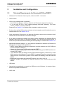
1
Getting Started with HC25
Siemens Cellular Engine
Version:
DocId:
Products:
02
HC25_startup_v02
HC25
User’s Guide
s
s
Getting Started with HC25
User’s Guide:
Getting Started with HC25
Version:
02
Date:
2007-05-25
DocId:
HC25_startup_v02
Status
Confidential / Released
Supported Products:
HC25
General Notes
Product is deemed accepted by recipient and is provided without interface to recipient’s products. The
documentation and/or product are provided for testing, evaluation, integration and information purposes.
The documentation and/or product are provided on an “as is” basis only and may contain deficiencies or
inadequacies. The documentation and/or product are provided without warranty of any kind, express or
implied. To the maximum extent permitted by applicable law, Siemens further disclaims all warranties,
including without limitation any implied warranties of merchantability, completeness, fitness for a particular purpose and non-infringement of third-party rights. The entire risk arising out of the use or performance of the product and documentation remains with recipient. This product is not intended for use in
life support appliances, devices or systems where a malfunction of the product can reasonably be
expected to result in personal injury. Applications incorporating the described product must be designed
to be in accordance with the technical specifications provided in these guidelines. Failure to comply with
any of the required procedures can result in malfunctions or serious discrepancies in results. Furthermore, all safety instructions regarding the use of mobile technical systems, including GSM products,
which also apply to cellular phones must be followed. Siemens or its suppliers shall, regardless of any
legal theory upon which the claim is based, not be liable for any consequential, incidental, direct, indirect,
punitive or other damages whatsoever (including, without limitation, damages for loss of business profits,
business interruption, loss of business information or data, or other pecuniary loss) arising out the use
of or inability to use the documentation and/or product, even if Siemens has been advised of the possibility of such damages. The foregoing limitations of liability shall not apply in case of mandatory liability,
e.g. under the German Product Liability Act, in case of intent, gross negligence, injury of life, body or
health, or breach of a condition which goes to the root of the contract. However, claims for damages arising from a breach of a condition, which goes to the root of the contract, shall be limited to the foreseeable
damage, which is intrinsic to the contract, unless caused by intent or gross negligence or based on liability for injury of life, body or health. The above provision does not imply a change on the burden of proof
to the detriment of the recipient. Subject to change without notice at any time. The interpretation of this
general note shall be governed and construed according to German law without reference to any other
substantive law.
Copyright
Transmittal, reproduction, dissemination and/or editing of this document as well as utilization of its contents and communication thereof to others without express authorization are prohibited. Offenders will
be held liable for payment of damages. All rights created by patent grant or registration of a utility model
or design patent are reserved.
Copyright © Siemens AG 2007
Trademark notice
MS Windows® is a registered trademark of Microsoft Corporation.
HC25_startup_v02
Confidential / Released
Page 2 of 57
2007-05-25
s
Getting Started with HC25
Contents
57
Contents
1
Introduction ................................................................................................................. 6
1.1
Related Documents ........................................................................................... 6
1.2
Abbreviations ..................................................................................................... 7
2
Installation and Configuration ................................................................................... 8
2.1
Technical Requirements for Running HC25 on DSB75 ..................................... 8
2.2
Choosing the Best Installation Strategy ............................................................. 9
2.3
Installing the Hardware .................................................................................... 10
2.4
Installation on Windows XP ............................................................................. 12
2.4.1 Installing Connection Manager and Preparing Driver Installation on
Windows XP........................................................................................ 12
2.4.2 Installing USB and Ethernet Drivers on Windows XP ......................... 14
2.5
Installation on Windows Vista .......................................................................... 17
2.5.1 Installing Connection Manager and Peparing Driver Installation on
Windows Vista .................................................................................... 17
2.5.2 Installing USB and Ethernet Drivers on Windows Vista ...................... 20
2.6
Special Installation Notes................................................................................. 21
2.7
Installed Devices and Tools on Windows XP, Windows Vista ......................... 22
2.8
Uninstalling Drivers and Siemens Connection Manager.................................. 24
2.8.1 Uninstalling Components if HC25 Connects to Windows XP ............. 24
2.8.2 Uninstalling Components if HC25 Connects to Windows Vista .......... 25
2.8.3 Uninstalling Components if HC25 is Disconnected............................. 27
2.8.4 Uninstalling Components of HC25 Preview Releases ........................ 29
2.8.4.1 Uninstalling Earlier Drivers .................................................. 29
2.8.4.2 Uninstalling Earlier Connection Manager ............................ 29
2.9
Updating HC25 Drivers .................................................................................... 30
2.9.1 Installing HC25 Drivers from Any Folder on Windows XP .................. 30
2.9.2 Installing HC25 Drivers from Any Folder on Windows Vista ............... 31
2.9.3 Installing HC25 Drivers from HC25 Mass Storage.............................. 32
2.10 Customizing Connection Manager and Driver Names..................................... 34
2.10.1 Customizing the Connection Manager................................................ 34
2.10.2 Customizing the Displayed Driver Names .......................................... 34
3
Using the HC25 Module ............................................................................................ 36
3.1
AT Command Interpreter ................................................................................. 36
3.2
Switching on the HC25 .................................................................................... 37
3.3
Switching off the HC25 .................................................................................... 37
3.4
Registering to the Network............................................................................... 37
3.5
Selecting UMTS or GSM.................................................................................. 38
3.6
Attaching to the HSDPA or GPRS Network ..................................................... 39
3.7
Defining the PDP Context ................................................................................ 39
3.8
Making a Voice Call (MO) ................................................................................ 40
3.9
Answering a Voice Call (MT) ........................................................................... 40
3.10 HSDPA or GPRS Data Transfer ...................................................................... 41
HC25_startup_v02
Confidential / Released
Page 3 of 57
2007-05-25
s
Getting Started with HC25
Contents
57
3.10.1 Data Transfer via Siemens Connection Manager on Windows XP..... 41
3.10.2 Data Transfer via Siemens Connection Manager on Windows Vista . 42
3.10.3 Data Transfer via Dial-Up Network ..................................................... 45
3.10.3.1 Local Echo Settings ............................................................ 46
4
Appendix I.................................................................................................................. 47
4.1
Adding and Configuring a New Dial-Up Network Connection .......................... 47
4.1.1 Creating a New Dial-up Network Connection ..................................... 47
4.1.2 Configuring a Dial-up Network Connection ......................................... 50
5
Appendix II................................................................................................................. 53
5.1
Configuring DSB75 Support Board and Adapter Board................................... 53
6
Index........................................................................................................................... 57
HC25_startup_v02
Confidential / Released
Page 4 of 57
2007-05-25
s
Getting Started with HC25
Figures
57
Figures
Figure 1:
Figure 2:
Figure 3:
Figure 4:
Figure 5:
Figure 6:
Figure 7:
Figure 8:
DSB75 Support Board with mounted adapter board and mini antenna cable
DSB75 Support Board with HC25 module and accessories connected.........
Deleting obsolete HC25 driver files, folders and subfolders ..........................
Folder tree of HC25 driver package ...............................................................
Adapter board - switch settings......................................................................
Mounting HC25 to DSB75 (exploded view )...................................................
DSB75 Support Board - switches, connectors, LEDs (overview)...................
Adapter board schematic ...............................................................................
HC25_startup_v02
Confidential / Released
Page 5 of 57
10
11
32
33
53
54
55
56
2007-05-25
s
Getting Started with HC25
1 Introduction
9
1
Introduction
HC25 is the first Siemens wireless module to offer Tri-band UMTS and Quad-Band GSM capability on the same device. The benefit is that the HC25 includes 3.6 Mbit/s HSDPA capability in
a UMTS network and also all common mobile connectivity features like voice, short messages,
GPRS and EGPRS.
The HC25 modules need to connect to an adequate host device, such as the DSB75 Support
Board. Designed to help application manufacturers and system integrators to test and develop
their HC25 host application, the DSB75 provides all interfaces and peripherals needed to run
the HC25.
The purpose of this document is to guide you through the process of connecting the hardware,
installing the software on a Windows XP or Windows Vista system, and, last but not least, making the first data transmission via UMTS and HSDPA.
1.1
Related Documents
Documents supplied with HC25
[1] HC25 Hardware Interface Description
[2] HC25 AT Command Set
[3] HC25 Release Notes
[4] Application Note 02: Audio Interface Design for HC25
[5] Application Note 16: Updating HC25 Firmware
[6] Application Note 22: Using TTY / CTM Equipment with HC25
[7] Application Note 26: Power Supply for Wireless Applications
[8] Application Note 37: GPS Antenna Integration for HC25
[9] Application Note 39: USB Interface Description
[10] Application Note 40: Thermal Solutions for HC25 Applications
[11] Remote SAT User’s Guide for HC25
Other related documents
[12] DSB75 Development Support Board Hardware Description
Designed for a wide range of Siemens wireless modules this document is ready for download on the Siemens Website: http://www.siemens.com/wm
HC25_startup_v02
Confidential / Released
Page 6 of 57
2007-05-25
s
Getting Started with HC25
1.2 Abbreviations
9
1.2
Abbreviations
Abbreviation
Description
APN
Access Point Name
CHAP
Challenge Handshake Authentication Protocol
DSB75
Short for DSB75 Development Support Board
GPRS
General Packet Radio Service
HSDPA
High-Speed Downlink Packet Access
IP
Internet Protocol
ME
Mobile Equipment
MO
Mobile Originated
MT
Mobile Terminated
PAP
Password Authentication Protocol
PDP context
Packet Data Protocol context
TA
Terminal Adapter
TE
Terminal Equipment
UICC
Universal Integrated Circuit Card
UMTS
Universal Mobile Telecommunication System
URC
Unsolicited Result Code
HC25_startup_v02
Confidential / Released
Page 7 of 57
2007-05-25
s
Getting Started with HC25
2 Installation and Configuration
9
2
Installation and Configuration
2.1
Technical Requirements for Running HC25 on DSB75
•
Windows XP or Windows Vista computer, minimum USB 1.1 connector
•
HC25 module
•
HC25 driver package either contained in
- the HC25 mass storage = delivery default for HC25 modules shipped from factory;
- or in an extra ZIP file = driver update packages delivered separately. File name:
"HC25_<release>_conman_install.zip" .
Please refer to Section 2.2 to decide which installation method to choose.
•
If drivers from earlier HC25 preview releases and test samples are still installed be sure to
uninstall them first. See Section 2.8.4.
•
Local Administrator Privileges on the particular Windows computer are required to install,
uninstall and use the Siemens Connection Manager.
•
If you wish to customize the names of the device drivers displayed in the Windows Device
Manager and/or the name of Connection Manager, you can edit the required strings in
some of the provided files before installing the driver package. For details see Section 2.10.
•
Appropriate hardware platform, e.g. the reference evaluation kit delivered by Siemens for
testing and developing HC25 applications:
- DSB75 Support Board providing the application interface between the HC25 USB port
and the computer's USB port.
- Adapter for mounting the HC25 module onto the DSB75
- 9 to 15 Volts power supply applied at the DSB75 for powering up the DSB75 and the connected HC25 module
- 1 mini antenna cable (50 Ohms) from the RF antenna connector ( Hirose U.FL) on the
HC25 module to the Hirose U.FL on the DSB75; 1 external RF antenna connecting to the
SMA connector of the DSB75 (product name: SMARTEQ MiniMag), both delivered with
DSB75
- Metal plate for grounding the external RF antenna, min. 20 cm x 20 cm
- Optional: Handset, eg. Handset for Siemens products from Votronic delivered with
DSB75
•
USB cable
•
Appropriate host application to control the USB ports under Windows, for example Hyperterminal integrated in Windows XP.
•
UICC card
HC25_startup_v02
Confidential / Released
Page 8 of 57
2007-05-25
s
Getting Started with HC25
2.2 Choosing the Best Installation Strategy
9
•
Service provider settings for access to the GPRS and HSDPA services, as a rule the following:
- APN (network operator specific Name of Access Point that connects the GSM network to
the Internet)
- Primary and secondary DNS
- IP address (DHCP or static)
- QoS settings
- User name and password
•
HC25 offers two ways to access the GPRS or HSDPA networks: either the Siemens Wireless Ethernet Adapter controlled by the Siemens Connection Manager or a dial-up network
connection set up via the Siemens HSDPA USB Modem. For details see Section 3.10.
•
Make sure to operate the HC25 always with the UICC card inserted in the card reader and
a valid SIM PIN entered. This is because most AT commands require SIM PIN authentication.
2.2
Choosing the Best Installation Strategy
The sequence of the installation steps depends on where the supplied driver package is
located:
1. HC25 modules shipped from factory have the driver package located on the mass storage.
Thus, the standard installation procedure is designed to be launched directly from the mass
storage.
Overview of installation steps: First connect the HC25 module to the DSB75 and start the
computer (see Section 2.3). Then install the Siemens Connection Manager to prepare the
driver installation (see Section 2.4.1 for Windows XP or Section 2.5.1 for Windows Vista).
Finally install the composite device drivers (see Section 2.4.2 for Windows XP or Section
2.5.2 for Windows Vista).
2. Latest driver updates are contained in the "HC25_<release>_conman_install.zip" file, usually ready for download from http://www.siemens.com/wm. If you wish to update to the latest driver versions, you have the following options:
- Installing the drivers from the mass storage
Overview of installation steps: First uninstall the existing drivers from the Windows computer. Switch off or unplug the module. Switch on or replug the module. Delete all old files
located in the mass storage and replace them with the new files, using exactly the same
directory tree. Switch off or unplug the module. Switch on or replug the module. Install
the Siemens Connection Manager and the composite device drivers from the mass storage.
If the HC25 module is intended to be inserted into more than one device take care that
the mass storage always contains the latest drivers.
See Section 2.9.3 for details.
- Installing the drivers from any folder inside the Windows system
Overview of installation steps: First uninstall the existing drivers from the Windows computer. Switch off or unplug the module. Install the Siemens Connection Manager. Switch
on or replug the module. Install the composite device drivers.
See Section 2.9.2 for details.
HC25_startup_v02
Confidential / Released
Page 9 of 57
2007-05-25
s
Getting Started with HC25
2.3 Installing the Hardware
11
2.3
Installing the Hardware
To properly connect the HC25 module and all accessories to the DSB75 Support Board follow
these steps:
• Check that all switches of the DSB75 Support Board are set as described in Chapter 5. See
also Figure 6 which shows an exploded view of all parts.
• Connect the one end of the mini antenna cable to the RF antenna connector (Hirose U.FL)
located on the module's top side.
• Mount the HC25 module upside down onto the 50-pin board-to-board connector of the
adapter board. Use the supplied M2 screws and nuts to screw the module to the adapter.
• Attach the adapter board to the 80-pin header located on the DSB75. Take gentle care that
all pins are aligned correctly, then press down evenly on the adapter board until it is firmly
seated. Use the supplied M3 screw and bolt to secure the adapter board to the DSB75 Support Board.
• Connect the other end of the mini antenna cable to the Hirose U.FL connector of the
DSB75.
• Screw the external antenna (MiniMag) into the SMA connector on the DSB75. To improve
the antenna performance use the metal plate for grounding. The external antenna should
be positioned in the center of the metal plate.
• Connect the Western plug of the handset to the Western jack on the DSB75.
• Connect the power cables to the red (BATT+) and black (Ground) connectors of the DSB75.
• Plug the USB cable to the computer's USB port and to the USB port of the DSB75. Press
the IGT key of the DSB75 to switch on the HC25 module. Start your Windows computer.
• To continue see Section 2.4 for Windows XP or Section 2.5 for Windows Vista.
USB connector
Power supply
DSB75 Support Board
Mini antenna cable
Adapter board
50-pin board-to-board
connector
Hirose U.FL connector
SMA connector
UICC/SIM reader
Western jack for handset
IGT key (left) and EMERG_OFF key (right)
Figure 1: DSB75 Support Board with mounted adapter board and mini antenna cable
HC25_startup_v02
Confidential / Released
Page 10 of 57
2007-05-25
s
Getting Started with HC25
2.3 Installing the Hardware
11
Figure 2: DSB75 Support Board with HC25 module and accessories connected
HC25_startup_v02
Confidential / Released
Page 11 of 57
2007-05-25
s
Getting Started with HC25
2.4 Installation on Windows XP
13
2.4
Installation on Windows XP
2.4.1
Installing Connection Manager and Preparing Driver Installation on Windows XP
After switching on or plugging the module, you will see the New Hardware Found Wizard coming up three times, requesting you to install the software for HC25 VCOM, HC25 NET and
HC25 Modem. Click Cancel in each dialog.
At the same time the module enumerates as mass storage device in your Windows XP system,
showing up as a Removable Disk assigned to the next free drive in the Windows Explorer. An
additional Windows system tray icon also indicates the mass storage device.
The wizard’s error message that pops up in the Windows taskbar shall be ignored. The installation will proceed automatically.
Note: If the installation fails to start automatically after you have canceled the three New Hardware Found Wizards simply navigate to the mass storage drive (= Removable Disk in the Windows Explorer) and double-click the provided “autorun.exe“ file.
HC25_startup_v02
Confidential / Released
Page 12 of 57
2007-05-25
s
Getting Started with HC25
2.4 Installation on Windows XP
13
Please wait a brief moment, then press Install to start the installation of the Connection Manager.
The progress of the installation will be indicated as illustrated below. It is possible that there are
up to 3 warning messages saying that the drivers are not digitally signed. Please ignore the
messages and press Continue anyway.
Now the installation of the Connection Manager is completed, and the driver software for the
composite device is preinstalled. The last installation dialog closes automatically.
See Section 2.4.2 to continue.
HC25_startup_v02
Confidential / Released
Page 13 of 57
2007-05-25
s
Getting Started with HC25
35
2.4.2
Installing USB and Ethernet Drivers on Windows XP
HC25 is installed as a composite device that comprises three virtual devices, one by one added
to your Windows XP system:
• Siemens HC25 USB Com Port driver
• Siemens HC25 Wireless Ethernet Adapter driver
• Siemens HC25 HSDPA USB Modem driver
During the installation, the HC25 USB interface will be assigned two virtual COM ports, one for
the virtual modem port and one for the virtual application port. Windows will automatically allocate the next available COM port to each virtual interface.
Once the Siemens Connection Manager installation has completed Windows detects the HC25
as a new USB composite device.
The Found New Hardware Wizard will
start. Click Next to proceed with the
installation of the "Siemens HC25 USB
Com Port".
The progress of the driver installation is
indicated.
There might be a warning message
saying that the driver is not digitally
signed. Please ignore the message and
press Continue anyway.
Click Finish to complete the installation of the "Siemens HC25 USB Com Port".
HC25_startup_v02
Confidential / Released
Page 14 of 57
2007-05-25
s
Getting Started with HC25
35
Now the installation of the "Siemens
HC25 Wireless Ethernet Adapter"
will start. Click Next.
The progress of the driver installation is indicated.
There might be a warning message
saying that the driver is not digitally
signed. Please ignore the message
and press Continue anyway.
Press Finish to complete the "Siemens HC25 Wireless Ethernet
Adapter" installation.
HC25_startup_v02
Confidential / Released
Page 15 of 57
2007-05-25
s
Getting Started with HC25
35
Now the installation of the "Siemens
HC25 HSDPA USB Modem" will
start. Click Next.
The progress of the driver installation is indicated.
There might be a warning message
saying that the driver is not digitally
signed. Please ignore the message
and press Continue anyway.
Press Finish to complete the "Siemens HC25 HSPDA USB Modem"
installation.
At this point the installation of all
three virtual devices is completed.
Windows XP notifies you that the
hardware is ready to use.
HC25_startup_v02
Confidential / Released
Page 16 of 57
2007-05-25
s
Getting Started with HC25
2.5 Installation on Windows Vista
35
2.5
Installation on Windows Vista
2.5.1
Installing Connection Manager and Peparing Driver Installation on Windows Vista
If you plug the HC25 module and install the HC25 drivers the first time, the New Hardware
Found wizard will pop up three times requesting you to install the software for the virtual
devices HC25 VCOM, HC25 NET and HC25 MODEM. Click Cancel in each dialog. If you reinstall the drivers these dialogs will usually not appear.
At the same time the module enumerates as a mass storage device in your Windows Vista system, showing up as a Removable Disk assigned to the next free drive in the Windows Explorer.
An additional Windows system tray icon also indicates the mass storage device.
If Autoplay is enabled on the computer you will be prompted
to select "Run autorun.exe".
If the installation does not start automatically, due to the
specific computer configuration, navigate to the mass storage drive and double-click the provided "autorun.exe" file.
HC25_startup_v02
Confidential / Released
Page 17 of 57
2007-05-25
s
Getting Started with HC25
2.5 Installation on Windows Vista
35
The autorun.exe icon starts to blink in the task bar of Windows Vista while showing this message:
"autorun.exe is requesting your permission"
Please click on the icon. A popup window "User Account Control" will show: "An unidentified
program wants access to your computer". Please press "Allow" to start the HC25 installer on
Windows Vista.
The installer will start to prepare the installation.
Now the HC25 Connection
Manager can be set up.
Press Install.
HC25_startup_v02
Confidential / Released
Page 18 of 57
2007-05-25
s
Getting Started with HC25
2.5 Installation on Windows Vista
35
The progress of the installation is indicated.
It is possible that there are up to 3 warning
messages saying that the drivers are not
digitally signed. Please ignore the messages and select the option Install this
driver software anyway.
The HC25 Connection Manager setup is completed.
The last installation dialog
box closes automatically.
See Section 2.5.2 to continue.
HC25_startup_v02
Confidential / Released
Page 19 of 57
2007-05-25
s
Getting Started with HC25
2.5 Installation on Windows Vista
35
2.5.2
Installing USB and Ethernet Drivers on Windows Vista
Once the HC25 Connection Manager installation has completed the HC25 will be set up as a
composite device comprising three virtual devices:
• Siemens HC25 USB Com Port driver
• Siemens HC25 Wireless Ethernet Adapter driver
• Siemens HC25 HSDPA USB Modem driver
An icon will show up in the Windows Vista
task bar to indicate the progress of the driver
installation.
Finally, the icon indicates that all devices are
ready to use.
HC25_startup_v02
Confidential / Released
Page 20 of 57
2007-05-25
s
Getting Started with HC25
2.6 Special Installation Notes
35
2.6
Special Installation Notes
If the installation does not work as expected, additional steps may be required, usually depending on the configuration of the Windows XP or Windows Vista computer.
HC25 does not show up as removable disk
• If the HC25 is not visible as removable disk
(mass storage device) when connected and
switched on the first time, it is possible that
the computer is configured to search the
Internet for Windows updates. As a result,
Windows is waiting for additional user
action.
• To avoid this scenario, it is recommended
to switch off this option before trying to
install the HC25.
Connection Manager installed, but driver installation does not start
• If the Connection Manager installation completes successfully as explained in Section 2.4.1
(Windows XP) or Section 2.5.1 (Windows Vista), but the driver installation does not start as
shown in Section 2.4.2 (Windows XP) or Section 2.5.2 (Windows Vista), it is possible that
the HC25 has failed to change from mass storage device to composite device functionality.
• In this case, please stop the mass storage function manually. To do so, right-click the
“Removable Disk“ drive and select Eject. The installation should proceed according to Section 2.4.2 or Section 2.5.2.
If the HC25 still shows up as removable device, point to the associated Windows system
tray icon, and select Stop from the resulting Safely Remove Hardware box. Then unplug
and replug the USB cable.
HC25_startup_v02
Confidential / Released
Page 21 of 57
2007-05-25
Getting Started with HC25
2.7 Installed Devices and Tools on Windows XP, Windows Vista
35
2.7
s
Installed Devices and Tools on Windows XP, Windows Vista
After successful installation, the HC25 module is
set up as composite device comprising the virtual
devices listed below. On Windows XP and Windows Vista, you can use the Device Manager to
check that all components are properly installed
and configured.
Siemens HC25 HSDPA USB Modem
• AT command and data interface, also referred
to as "Modem" interface if queried using the AT^SQPORT command.
• Intended particularly for HSDPA and GPRS data connections.
• The virtual COM port Windows has assigned to this interface is listed in the Device Manager
under Modems and under Control Panel | Phone and Modem Options.
• The port number can be gathered from the property pages. This COM port can be used to
set up dial-up network connections. The bit rate set by default on the modem property page
is not relevant for USB and can be left unchanged. On the Advanced tab you can put the
command string used to define the PDP context for your GPRS / HSDPA provider. See also
Section 3.7.
HC25_startup_v02
Confidential / Released
Page 22 of 57
2007-05-25
Getting Started with HC25
2.7 Installed Devices and Tools on Windows XP, Windows Vista
35
s
Siemens HC25 USB Com Port
• AT command interface, also referred to as "Application" interface if queried using the
AT^SQPORT command.
• Mainly intended for controlling the HC25 module, for receiving URCs, also for sending,
receiving, writing and reading short messages. Not intended as data interface for HSDPA
and GPRS.
• The virtual COM port Windows has assigned to this port is listed in the Device Manager
under Ports (COM&LPT).
Siemens HC25 Wireless Ethernet Adapter
• Wireless network adapter intended for HSDPA and GPRS data connections.
• Listed in the Device Manager under Network adapters.
• Software controlled by the Siemens Connection Manager. To open the program in Windows XP, click Start, point to Programs, select Siemens, select HC25 HSDPA USB Modem
and click HC25 Connection Manager. See Section 3.10 and Section 3.10.1 (Windows XP)
or Section 3.10.2 (Windows Vista) for details on how to set up a connection.
HC25_startup_v02
Confidential / Released
Page 23 of 57
2007-05-25
Getting Started with HC25
2.8 Uninstalling Drivers and Siemens Connection Manager
35
2.8
s
Uninstalling Drivers and Siemens Connection Manager
The steps required to remove the installed HC25 components vary depending on whether the
module switched on or off.
The procedures are almost the same for Windows XP and Windows Vista except for the minor
differences described below.
2.8.1
Uninstalling Components if HC25 Connects to Windows XP
1. Ensure that the module is connected to the computer’s USB port and switched on.
2. Close all HC25 applications, for example the HC25 Connection Manager or terminal program(s) connected to the virtual USB port(s).
3. Open the Control Panel. Click Add or Remove Programs and select HC25 Connection Manager. Press Remove to select the uninstaller of the Connection Manager and the HC25 drivers.
4. Press Yes to start the uninstaller.
5. The HC25 Connection Manager and all HC25 drivers will be removed.
HC25_startup_v02
Confidential / Released
Page 24 of 57
2007-05-25
Getting Started with HC25
2.8 Uninstalling Drivers and Siemens Connection Manager
35
2.8.2
s
Uninstalling Components if HC25 Connects to
Windows Vista
1. Ensure that the module is connected to the computer’s USB port and switched on.
2. Close all HC25 applications, for example the HC25 Connection Manager or the host application(s) connected to the virtual USB port(s).
3. Open the Control Panel. Click Programs and Features and point to the HC25 Connection
Manager. Double-click or right-click HC25 Connection Manager to start the uninstaller, then
click Yes to confirm the resulting uninstall message.
4. A popup window named User Account Control will display the message "An unidentified
program wants access to your computer". Press the Allow button to launch the uninstaller
on Windows Vista.
5. Wait a brief moment until the HC25
Connection Manager closes and all
drivers are removed.
HC25_startup_v02
Confidential / Released
Page 25 of 57
2007-05-25
Getting Started with HC25
2.8 Uninstalling Drivers and Siemens Connection Manager
35
s
6. The Found New Hardware wizard will pop up three times because, after driver clean-up,
Windows Vista starts searching for new drivers. Press Cancel to abort the search.
In some cases, the Found New
Hardware wizards may indicate
"Unknown Device" instead of HC25
VCOM, HC25 NET and HC25
MODEM. The procedure is the
same - simply press Cancel three
times.
7. The HC25 Connection Manager and the HC25 drivers are removed now.
Only the two files files hc25usbser.sys“ and “hc25usbnet.sys are left unchanged in the
..\WINDOWS\system32\drivers folder. Yet, this is no problem, as they will be overwritten
next time you re-install the drivers.
HC25_startup_v02
Confidential / Released
Page 26 of 57
2007-05-25
Getting Started with HC25
2.8 Uninstalling Drivers and Siemens Connection Manager
35
2.8.3
s
Uninstalling Components if HC25 is Disconnected
If disconnected or switched off, the HC25 module is not visible on the Windows XP or Windows
Vista computer unless you enable the operating system to show hidden devices. The purpose
of this section is to describe how to uninstall HC25 components in such case. The dialog boxes
show Windows Vista, but Windows XP is quite similar.
1. Remove the HC25 Connection Manager as described in Section 2.8.1.
As a result, the Connection Manager software will be uninstalled, but the HC25 drivers are
not.
2. Although not visible, the HC25 drivers are still blocking two virtual COM ports. To free the
ports hidden devices must be shown as follows:
On Windows XP, open the Control Panel, click System and select the Advanced tab.
On Windows Vista, open the Control Panel, select System and Maintenance, click System
and select Advanced system settings on the left panel of the dialog box.
Then press the Environment Variables button. In the resulting dialog box point to the System variables section and press the New button.
Enter the new system variable "DEVMGR_SHOW_NONPRESENT_DEVICES" and set
value "1".
HC25_startup_v02
Confidential / Released
Page 27 of 57
2007-05-25
Getting Started with HC25
2.8 Uninstalling Drivers and Siemens Connection Manager
35
s
3. Open the Device Manager (from Control Panel). Note that if the Device Manager is already
open you need to close and re-open it to update the status of the devices. From the View
menu select Show hidden devices.
4. All hidden virtual HC25 devices are listed now. Right-click each device, one by one, select
Uninstall and confirm the resulting uninstall messages.
The example shows how to uninstall the Siemens HC25 USB Com Port. The Siemens
HC25 Wireless Ethernet Adapter and the Siemens HC25 HSDPA USB Modem must be
uninstalled in the same way.
HC25_startup_v02
Confidential / Released
Page 28 of 57
2007-05-25
Getting Started with HC25
2.8 Uninstalling Drivers and Siemens Connection Manager
35
2.8.4
s
Uninstalling Components of HC25 Preview Releases
The following procedures apply only to drivers of earlier HC25 releases supplied as preview
samples for testing only. These drivers were available only for Windows XP.
2.8.4.1
Uninstalling Earlier Drivers
1. Under Windows XP, open the Device Manager and
select the drivers as described in Section 2.7. Keep
in mind that the drivers are listed in the Device Manager only when the module is switched on. Rightclick the driver and, from the resulting menu, select
Uninstall.
If the module is disconnected first follow the steps
provided in Section 2.8.3 and enable the Device
Manager to show hidden devices.
2. Under ..\WINDOWS\system32\drivers remove the
two files “hcusbser.sys“ and “hcusbnet.sys“. (Please note that the newly installed HC25
drivers will now be set up as “hc25usbser.sys“ and “hc25usbnet.sys).
3. Under ..\WINDOWS\INF check for old “oem*.inf“ and “oem*.pnf“ files and remove all files
related to earlier customer samples.
To do so, open the currently installed “oem*.inf“ file(s) and compare the content with the
“hcser.inf“, “hcnet.inf“and "hcmdm.inf" supplied with the latest release. All “oem*.inf“ and
associated “oem*.pnf“ files based on information from old “hcser.inf“, “hcnet.inf“ and
“hcmdm.inf“files must be removed.
An easy way to compare the content of these files is checking the information given in the
[Siemens] section, such as the two examples shown below:
Examples:
[SIEMENS]
%hcwwan.DeviceDesc_hc1%
= hcwwan.ndi, USB\VID_0681&PID_0040&MI_01
[SIEMENS]
%hcwwan.DeviceDesc_hc1%
= hcwwan.ndi, USB\VID_05C6&PID_7001&MI_01
2.8.4.2
Uninstalling Earlier Connection Manager
Old versions of the Siemens Connection Manager were installed in Windows XP under Program Files | Siemens | ConnectionManager. To uninstall the program simply remove the "conman.exe" file.
Any shortcuts and icons must be deleted manually.
HC25_startup_v02
Confidential / Released
Page 29 of 57
2007-05-25
s
Getting Started with HC25
2.9 Updating HC25 Drivers
35
2.9
Updating HC25 Drivers
Driver updates are contained in a ZIP file named "HC25_<release>_conman_install.zip". The
ZIP file is either delivered separately or ready for download from http://www.siemens.com/wm.
The following sections describe how to install the new drivers either from any location on a Windows XP computer (see Section 2.9.1) or a Windows Vista computer (see Section 2.9.2) or
from the HC25 mass storage (see Section 2.9.3).
2.9.1
Installing HC25 Drivers from Any Folder on Windows XP
1. Switch off the HC25 module or unplug the USB cable.
2. Copy or unpack the new driver package to any folder on your Windows XP computer.
The folder tree must be the same as shown in Section 2.9.3, Figure 4. Therefore, do not
copy or unpack the files into one folder only.
Recommendation: When you extract the supplied "HC25_<release>_conman_install.zip"
take care to retain the folders and subfolders stored in the ZIP archive.
3. Double-click the "autorun.exe" file from the dezipped driver package.
4. The installation of the Siemens Connection Manager will start and, at the same time, the
composite device driver software will be preinstalled. Simply follow the screens described
in Section 2.4.1. The last installation dialog closes automatically.
5. Now, switch on the HC25 module or replug the USB cable.
6. Windows will detect the HC25 module as a new device. The New Hardware Found wizard
pops three times, prompting you to install the following devices:
- Siemens HC25 USB Com Port driver
- Siemens HC25 Wireless Ethernet Adapter driver
- Siemens HC25 HSDPA USB Modem driver
To do so, follow the screens described in Section 2.4.2, i.e. simply press Next in each dialog, using the option Install the software automatically (Recommended).
Keep in mind that, before the composite device drivers are installed, the HC25 enumerates as
mass storage if the factory default settings of the AT^SUSB command are left unchanged:
parameter <start> equals "MdmNet" and timeout <mnto> equals 10 seconds. The mass storage is not needed, but you may be required to take the following precautions:
- If the installation of all three drivers completes before the <mnto> timeout expires the
mass storage will be deactivated automatically. But as 10 seconds are typically not
enough for all three drivers it is very likely that the HC25 enumerates as mass storage
during the installation. As a result, the driver installation (step 6 above) may be halted, for
example after the first (or already the second) driver was set up. Yet, this is nothing to
worry about - all you need to do is manually ejecting the mass storage. So, right-click the
Removable Disk drive inside the Windows Explorer and select Eject. This will deactivate
the mass storage functionality, and at the same time, cause the New Hardware Found
wizards for the next one or two drivers to pop up.
- If you prefer to install driver updates always from a location other than the HC25 mass
storage, you can disable the <mnto> timeout of the AT^SUSB command (set 0 seconds).
The setting is non-volatile. For details on AT^SUSB please refer to [2].
IMPORTANT: To avoid mixing up the driver packages located in the mass storage and in any
other folder be sure to run the "autorun.exe" only from the new dezipped driver package.
HC25_startup_v02
Confidential / Released
Page 30 of 57
2007-05-25
s
Getting Started with HC25
2.9 Updating HC25 Drivers
35
2.9.2
Installing HC25 Drivers from Any Folder on Windows Vista
1. Switch off the HC25 module or unplug the USB cable.
2. Copy or unpack the new driver package to any folder on your Windows XP computer.
The folder tree must be the same as shown in Section 2.9.3, Figure 4. Therefore, do not
copy or unpack the files into one folder only.
Recommendation: When you extract the supplied "HC25_<release>_conman_install.zip"
take care to retain the folders and subfolders stored in the ZIP archive.
3. Double-click the "autorun.exe" file from the dezipped driver package.
4. The installation of the Siemens Connection Manager will start and, at the same time, the
composite device driver software will be preinstalled. Simply follow the screens described
in Section 2.5.1. The last installation dialog closes automatically.
5. Now, switch on the HC25 module or replug the USB cable.
6. The installation of the composite device drivers continues automatically as described in
Section 2.4.2.
On Windows Vista, the 10s timeout <mnto> of the AT^SUSB command will often be sufficient
for the composite device driver installation, eliminating the need for HC25 to temporarily enumerate as mass storage. However, if 10 seconds are not enough, the HC25 enumerates as
mass storage, and the driver installation (step 6 above) may be halted as explained in Section
2.9.1 for Windows XP. In this case, manually eject the mass storage. To do so, right-click the
Removable Disk drive inside the Windows Explorer and select Eject. This will deactivate the
mass storage functionality, and the installation will proceed.
If you prefer to install driver updates always from a location other than the HC25 mass storage,
you can disable the <mnto> timeout of the AT^SUSB command (set 0 seconds). The setting is
non-volatile. For details on AT^SUSB please refer to [2].
IMPORTANT: To avoid mixing up the driver packages located in the mass storage and in any
other folder be sure to run the "autorun.exe" only from the new dezipped driver package.
HC25_startup_v02
Confidential / Released
Page 31 of 57
2007-05-25
s
Getting Started with HC25
2.9 Updating HC25 Drivers
35
2.9.3
Installing HC25 Drivers from HC25 Mass Storage
To ensure that the driver update installation can be started from the mass storage of the HC25
we recommend to follow the steps listed below. By this approach, the factory settings of the
AT^SUSB command can be left unchanged: parameter <start> equals "MdmNet" and timeout
<mnto> equals 10s.
1. Uninstall the drivers and the HC25 Connection Manager as described in Section 2.8.
2. Switch off or unplug the module, then switch on or replug the module.
3. Abort the installer if started automatically (press Cancel in all three New Hardware Found
wizards).
4. Because no installed drivers are found (within the above AT^SUSB timeout <mnto>), the
HC25 module enumerates as mass storage, usually showing up as Removable Disk
assigned to the next free drive of the Windows Explorer. Navigate to this drive and delete
all existing files, folders and subfolders containing the old driver package (see Figure 3).
Figure 3: Deleting obsolete HC25 driver files, folders and subfolders
HC25_startup_v02
Confidential / Released
Page 32 of 57
2007-05-25
s
Getting Started with HC25
2.9 Updating HC25 Drivers
35
5. Copy or unpack the new driver package to the mass storage drive.
The folder tree must be the same as shown below. Therefore, do not copy or unpack the
files into one folder only.
Recommendation: When you extract the supplied "HC25_<release>_conman_install.zip"
take care to retain the folders and subfolders stored in the ZIP archive.
Figure 4: Folder tree of HC25 driver package
6. Close the Windows Explorer and switch off or unplug the HC25 module.
Now the module is prepared for easy installation from the mass storage. You can switch on or
replug the HC25 module any time and proceed as described in Section 2.4 for Windows XP or
Section 2.5 for Windows Vista.
HC25_startup_v02
Confidential / Released
Page 33 of 57
2007-05-25
Getting Started with HC25
2.10 Customizing Connection Manager and Driver Names
35
2.10
s
Customizing Connection Manager and Driver Names
Manufacturers of HC25 applications are given the flexibility to customize the names of the Connection Manager and the composite device drivers of HC25, rather than using the names set
by factory default.
2.10.1
Customizing the Connection Manager
To customize the Connection Manager you can edit the "conman.ini" file using any text editor.
It is recommended to do so before installing the HC25 driver package.
The "conman.ini" file is located in the same directory as the "conman.exe" (Connection Manager executable). The factory default settings are shown below. The ProductName string specified in the "conman.ini" file appears in the title bar of the Connection Manager dialog box.
[ConMan]
ProductName = Siemens Connection Manager
CompanyName = Siemens AG
Both the ProductName and the CompanyName can be replaced with customer specific strings
as shown in the example below.
[ConMan]
ProductName = My Own Connection Tool
CompanyName = My Company
2.10.2
Customizing the Displayed Driver Names
If you would like to change the driver names displayed in the Device Manager as well, you need
to change strings inside the INF files provided with the HC25 driver package:
hc25mdm.inf, hc25net.inf and hc25ser.inf.
You can use any text editor. The changes have to be done prior to installing the drivers.
Be careful to change only the strings listed below. Do not change any other strings, because
otherwise the drivers may not work properly.
In the following examples the name "Siemens" has been replaced with "My Company".
HC25_startup_v02
Confidential / Released
Page 34 of 57
2007-05-25
Getting Started with HC25
2.10 Customizing Connection Manager and Driver Names
35
s
Changes inside the hc25mdm.inf file
[Version]
...
DriverPackageDisplayName="My Company HC25 HSDPA Modem"
...
[Strings]
SIEMENS
= "My Company"
SIEMENS_hc2 = "My Company HC25 HSDPA USB Modem"
HCUSBSER
= "My Company HC25 USB Device for Legacy Serial Communication"
Changes inside the hc25net.inf file
[version]
...
DriverPackageDisplayName="My Company HC25 HSDPA NDIS"
...
[Strings]
SIEMENS
= "My Company"
hcwwan.DeviceDesc_hc1 = "My Company HC25 Wireless Ethernet Adapter"
hcwwan.Service.DispName = "My Company HC25 USB-NDIS miniport"
Changes inside the hc25ser.inf file
[Version]
...
DriverPackageDisplayName="My Company HC25 USB Port"
...
[Strings]
SIEMENS
= "My Company"
ComDevice_hc3 = "My Company HC25 USB Ctrl Port"
ComDevice_hc0 = "My Company HC25 USB Com Port"
HCUSBSER
= "My Company HC25 USB Device for Legacy Serial Communication"
HC25_startup_v02
Confidential / Released
Page 35 of 57
2007-05-25
s
Getting Started with HC25
3 Using the HC25 Module
46
3
Using the HC25 Module
The following examples show the basic steps required to register to the network, to select
UMTS mode or GSM mode and to attach to HSDPA or GPRS.
The examples are based on a UICC card provisioned by the German network operator TMobile. The used UICC card is capable of UMTS and GSM and enables the subscriber to
switch back and forth between both networks.
3.1
AT Command Interpreter
AT commands can be entered on two interfaces of the HC25 module:
• Siemens USB Com Port
• Siemens HSDPA USB Modem
Yet, we recommend that the Siemens HSDPA USB Com Port be used for controlling the HC25
module, eg. for entering AT commands and receiving URCs, while the Siemens HSDPA USB
Modem is mainly intended for use as a modem. For greater detail refer to [2], especially sections "AT Command Interpreter" and "Unsolicited Result Code Presentation".
As described in Section 2.7, each interface is assigned a virtual COM port of its own, which
enables accessing the interface from the host application or, accordingly, the dial-up network
connection. To easily identify both interfaces you can use the AT^SQPORT command:
AT^SQPORT
Application
On the AT command interface, the Siemens
HSDPA USB Com Port is referred to as "Application".
OK
AT^SQPORT
Modem
On the AT command interface, the Siemens
HSDPA USB Modem is referred to as
"Modem".
OK
If you need to operate the HC25 from both interfaces at a time, bear in mind that both are handled by the same AT command interpreter. As a result, AT commands entered on both interfaces are not executed in parallel but sequentially, one after the other. So, an AT command
issued on one interface will be buffered on this interface to be executed after the other interface
has completed processing earlier AT command(s). The buffered command string is not echoed, but will be indicated when executed.
HC25_startup_v02
Confidential / Released
Page 36 of 57
2007-05-25
s
Getting Started with HC25
3.2 Switching on the HC25
46
3.2
Switching on the HC25
The HC25 can be started by pressing the IGT key of the DSB75. Please wait approximately 2
seconds before using the module, for example before entering AT commands.
3.3
Switching off the HC25
To shut down the HC25 module, enter the AT^SMSO command. This enables the ME to save
all data and perform an orderly shutdown.
AT^SMSO
OK
The ME switches off.
The HC25 module can also be switched off by using the IGT line as described in [2], Section
AT^SCFG and in [1], Section "Configuring the IGT Line for Use as ON/OFF Switch")
3.4
Registering to the Network
Make sure to operate the HC25 always with the UICC card inserted in the DSB75 card reader
and a valid SIM PIN entered. This is because most AT commands require SIM PIN authentication.
Write command: AT+CPIN=<pin>[, <new pin>]
AT+CPIN?
+CPIN: SIM PIN
OK
AT+CPIN=“1234“
OK
AT+CPIN?
+CPIN: READY
OK
HC25_startup_v02
Confidential / Released
Entering the SIM PIN.
Page 37 of 57
2007-05-25
s
Getting Started with HC25
3.5 Selecting UMTS or GSM
46
3.5
Selecting UMTS or GSM
The GSM 07.07 operator selection command AT+COPS has been enhanced to enable the
subscriber to select whether to use UMTS or GSM. You can quickly switch back and forth
between both network types while the ME remains registered.
Write command: AT+COPS=<mode>[, <format>[, <oper>[, <act>]]]
The parameter <act> (access technology) can take the values listed below. The parameter is
stored non-volatile.
0
GSM network
2
UMTS network
Note: By factory default, an automatic network selection mode is set which enables the ME to
select either UMTS or GSM, depending on the network coverage. This automatic mode
remains enabled until you explicitly set either UMTS or GSM using the <act> parameter of
AT+COPS. Setting the <act> parameter forces the ME to select either UMTS only or accordingly, GSM only. If the specified network is not available, the network registration will be disabled. Setting <mode> to 0 without choosing a specific <act> enables the automatic selection
mode once again.
AT+COPS?
+COPS: 0,0,"T-Mobile D",2
Querying the current network mode.
The ME is registered to the German operator T-Mobile and uses UMTS.
OK
AT+COPS=0,,,0
#(or AT+COPS=,,,0)
OK
AT+COPS?
+COPS: 0,0,"T-Mobile D",0
Selecting the GSM network.
Query the current network type.
The response confirms that the ME has
changed to the GSM network.
OK
AT+COPS=0,,,2
#(or AT+COPS=,,,2)
OK
AT+COPS?
+COPS: 0,0,"T-Mobile D",2
Selecting the UMTS network.
OK
AT+CPIN?
+CPIN: READY
There is no need to enter the SIM PIN
again.
OK
AT+COPS=0
OK
Setting automatic network selection mode.
Furthermore, the command AT+COPS serves to query or specify several modes of selecting
the GSM network operator. These functions are not discussed in this document.
HC25_startup_v02
Confidential / Released
Page 38 of 57
2007-05-25
s
Getting Started with HC25
3.6 Attaching to the HSDPA or GPRS Network
46
3.6
Attaching to the HSDPA or GPRS Network
After PIN authentication, the HC25 module automatically tries to attach to the HSDPA or,
accordingly, GPRS network.
AT+CGATT?
+CGATT: 1
Querying the current service state.
The ME is attached, depending on the
selected network type (see AT+COPS), it is
either attached to the HSDPA or GPRS service.
OK
3.7
Defining the PDP Context
Use the AT+CGDCONT command to configure the correct provider settings. The PDP context
is stored non-volatile.
Write command:
AT+CGDCONT=<cid>[, <PDP_type>[, <APN>[, <PDP_addr>]]]
AT+CGDCONT=1,"IP","internet.t-mobile"
OK
AT+CGDCONT?
+CGDCONT: 1,"IP","internet.t-mobile","",0,0
OK
Specifying the PDP context (example shows
the APN of the German network provider TMobile).
Checking the current PDP context definition.
The focus of this document is only on the parameters <cid>, <PDP_type> and <APN>. The
string parameters must be enclosed in quotation marks.
Under Windows XP, the PDP context can, optionally, be entered on the Modem property page
as described in Section 2.7.
HC25_startup_v02
Confidential / Released
Page 39 of 57
2007-05-25
s
Getting Started with HC25
3.8 Making a Voice Call (MO)
46
3.8
Making a Voice Call (MO)
The commonly used GSM 07.07 dialing command ATD is fully applicable both in the UMTS
and the GSM network.
To make a mobile originated voice call enter ATD, type the destination number and add a semicolon. The result code OK will be returned immediately after dialing, prior to call setup.
To end the call, use the AT+CHUP command (ATH is for data calls only).
ATD030111111111;
OK
at+clcc
+CLCC:
1,0,0,0,0,"030111111111",129,"Tom"
The HC25 subscriber makes a voice call.
Checking the call status (MO call is active).
The HC25 subscriber terminates the call.
AT+CHUP
OK
Checking the call status (no call).
at+clcc
OK
3.9
Answering a Voice Call (MT)
A mobile terminated voice call is indicated by the RING URC. To answer the call, enter ATA.
To terminate the call use AT+CHUP.
HC25_startup_v02
Confidential / Released
Page 40 of 57
2007-05-25
s
Getting Started with HC25
3.10 HSDPA or GPRS Data Transfer
46
3.10
HSDPA or GPRS Data Transfer
HC25 offers two alternatives to access the GPRS or HSDPA networks:
• The Siemens HC25 Connection Manager provided for the Siemens Wireless Ethernet
Adapter. See Section 3.10.1. The program is part of the HC25 driver package.
• A dial-up network connection via the installed Siemens HSDPA USB Modem as described
in Section 3.10.3.
In either case the ME must be registered to the network. So, before trying to connect to the data
services ensure that SIM PIN authentication was done from the host application. To take
advantage of HSDPA make sure that the <act> parameter of AT+COPS equals "2". For GPRS
the parameter shall be "0". It is recommended to configure these settings on the Siemens
HSDPA USB Com Port.
3.10.1
Data Transfer via Siemens Connection Manager on
Windows XP
This section describes how to use the Siemens HC25 Connection Manager on Windows XP.
• To open the program in Windows
XP, click Start, point to Programs,
select Siemens, select HC25
HSDPA USB Modem and click
HC25 Connection Manager.
• Use the Select Device listbox to
choose the Siemens Wireless Ethernet Adapter. When opened the
first time or after disabling the
adapter, the listbox may be empty.
• Check the APN Name box and
enter the APN (Access Point
Name) of your service provider.
• If necessary, check the Authentication Preference box and select the
type of authentication protocol.
Otherwise, PAP and CHAP apply
by default. Username and password are also provider dependent.
• Press the Connect button to set up
a connection. Then simply open
your Internet browser. The box on
the rightmost bottom represents
the signal strength.
• To close the connection press the Disconnect button (available when connected).
The Auto Connect check box on the leftmost bottom can be activated if you want the Siemens
Wireless Ethernet Adapter to automatically connect to the network each time you restart the
HC25. This option can be used particularly with a flat rate subscription. In this case, take care
that the SIM PIN authentication is also done automatically.
HC25_startup_v02
Confidential / Released
Page 41 of 57
2007-05-25
s
Getting Started with HC25
3.10 HSDPA or GPRS Data Transfer
46
3.10.2
Data Transfer via Siemens Connection Manager on
Windows Vista
This section describes how to use the Siemens Connection Manager on Windows Vista.
Windows Vista requires the user to log on a administrator, not only for installing, but also for
using the Siemens Connection Manager. The administrator privileges for using the program
can be set either temporarily or permanently.
Temporary administrator privileges for the Siemens Connection Manager
Click the Start menu, point to Programs, select Siemens, select HC25 HSDPA USB Modem.
Right-click the HC25 Connection Manager. From the resulting context menu, select the option
Run as administrator.
A popup window "User Account Control" will show: "An unidentified program wants access to
your computer". Please press "Allow" to start the program.
HC25_startup_v02
Confidential / Released
Page 42 of 57
2007-05-25
s
Getting Started with HC25
3.10 HSDPA or GPRS Data Transfer
46
Permanent administrator privileges for the Siemens Connection Manager
A more convenient way is to enable the Siemens Connection Manager to always start with
administrator privileges:
To do so, open the Windows Vista Explorer, select the installation path, e.g. c:\Program
Files\Siemens\HC25 Connection Manager\. Right-click the "conman.exe" file and select Properties from the resulting the context menu.
The conman.exe Properties dialog box opens.
Select the Compatibility tab. In the Privilege Level
section, check Run this program as an administrator.
HC25_startup_v02
Confidential / Released
Page 43 of 57
2007-05-25
s
Getting Started with HC25
3.10 HSDPA or GPRS Data Transfer
46
Using Siemens Connection Manager on Windows Vista
•
•
•
•
•
Use the Select Device listbox to
choose the Siemens Wireless Ethernet Adapter. When opened the
first time or after disabling the
adapter, the listbox may be empty.
Check the APN Name box and
enter the APN (Access Point
Name) of your service provider.
If necessary, check the Authentication Preference box and select the
type of authentication protocol.
Otherwise, PAP and CHAP apply
by default. Username and password are also provider dependent.
Press the Connect button to set up
a connection. Then simply open
your Internet browser. The box on
the rightmost bottom represents
the signal strength.
To close the connection press the
Disconnect button (available when
connected).
The Auto Connect check box on the leftmost bottom can be activated if you want the Siemens
Wireless Ethernet Adapter to automatically connect to the network each time you restart the
HC25. This option can be used particularly with a flat rate subscription. In this case, take care
that the SIM PIN authentication is also done automatically.
HC25_startup_v02
Confidential / Released
Page 44 of 57
2007-05-25
s
Getting Started with HC25
3.10 HSDPA or GPRS Data Transfer
46
3.10.3
Data Transfer via Dial-Up Network
The focus of this section is on Windows XP. Instructions on how to create a new dial-up network
connection on Windows XP can be found in Chapter 4. Windows Vista is not shown in detail.
Before dialing, make sure that the virtual COM port is not used by any application (eg. by a terminal program or by the host application).
Also, ensure that you have the PDP context for your
service provider defined by using the AT+CGDCONT command. The command string can be
entered either on the Modem property page on the
Windows Control Panel or in the host application
(see Section 2.7 and Section 3.7).
From the Control Panel of Windows XP, choose Network Connections and select the dial-up network
connection created for HC25 (on Windows Vista go
to Network and select Network and Sharing Center).
The correct dial string *99***1# should already be
given, if entered in the Phone number box when the
dial-up network connection was added. Otherwise,
you can type the number here before dialing.
User name and password may or may not be
required, depending on the network operator.
The connection is properly established when the following messages are reported:
Note that the message showing “Speed
115.2 kbps“ can be ignored. It is only a Windows standard message for modems which
is neither relevant for USB nor does it reflect
the true data rate used on the air interface.
To verify the data rates for up- and/or downlink, you can use, for example, the file
download status dialog of your Internet
browser.
HC25_startup_v02
Confidential / Released
Page 45 of 57
2007-05-25
s
Getting Started with HC25
3.10 HSDPA or GPRS Data Transfer
46
Terminating the dial-up network connection
To stop a HSDPA or GPRS data connection disconnect the dial-up network connection. This
can be done in two ways:
1. Double-click the dial-up network connection
icon in the system tray. In the resulting connection status dialog press the Disconnect
button.
2. The other way is available on the Network
Connections page of the Control Panel: Rightclick the active connection to open a context
menu where to choose Disconnect.
3.10.3.1
Local Echo Settings
Due to the initialization strings typically set by modems, a dial-up network connection may automatically change the local echo settings: Opening a dial-up network connection deactivates
(ATE0) and activates (ATE1) the local echo. Releasing the dial-up network connection deactivates the echo once again (ATE0). As modem and application interface are controlled from the
same AT command interpreter the change takes effect on both interfaces.
Therefore, after closing a dial-up network connection you are advised to wait a few seconds
before entering an AT command on the Application interface. Otherwise, it is possible that the
echo deactivation command ATE0 is still being executed on the modem interface while another
AT command is already entered on the application interface. As a result, the AT command
response expected on the application interface may appear incomplete.
Likewise, if you enter an AT command on the application interface in parallel to a dial-up network connection running on the modem interface at the time when the echo is deactivated take
into account that the expected response may be indicated either partially or not at all.
Each time after closing a dial-up network connection you are advised to send the ATE1 command to enable the local echo again.
HC25_startup_v02
Confidential / Released
Page 46 of 57
2007-05-25
s
Getting Started with HC25
4 Appendix I
52
4
Appendix I
4.1
Adding and Configuring a New Dial-Up Network Connection
This section will help you create and configure a new dial-up network connection when using
the installed Siemens HSDPA USB Modem to access the GPRS or HSDPA network.
All step-by-step instructions and figures provided below refer to Windows XP. In Windows
Vista, use the Network and Sharing Center to configure a dial-uo network connection.
4.1.1
Creating a New Dial-up Network Connection
There are several ways to start creating a new dial-up network connection. For example, open
the Control Panel, double-click Network Connections, select New connection. Another way is
to select Settings from the Start menu, click Network Connections, then New Connection Wizard.
In any case, the Network Connection Wizard opens. Click Next to continue. Put a check mark
on Connect to the Internet and click Next.
HC25_startup_v02
Confidential / Released
Page 47 of 57
2007-05-25
Getting Started with HC25
4.1 Adding and Configuring a New Dial-Up Network Connection
52
s
Select the option Set up my connection manually and click Next. Select Connect using a dialup modem and click Next.
Select the modem that you want to use for the dial-up network connection. Click Next to continue. Type an appropriate Connection name and click Next.
HC25_startup_v02
Confidential / Released
Page 48 of 57
2007-05-25
Getting Started with HC25
4.1 Adding and Configuring a New Dial-Up Network Connection
52
s
In the Phone number box, put the
dial string *99***1# commonly
used to access the GPRS network.
Note: The number "1" added
before the hash determines that
the first PDP context shall be used.
The number must be identical to
the <cid> value set with AT+CGDCONT (see Section 3.7).
Depending on the network, you
may be required to put a User
name and a Password for the dialup network connection. If not
required, you may leave all boxes
empty. Click Next and, in the
resulting dialog, click Finish.
This will cause the Connect… dialog to appear (screen is shown in
Section 4.1.2). Yet, at this
moment, it is recommended that
you press Cancel in order to
check, and if necessary, to configure the dial-up network connection
as described in Section 4.1.2.
HC25_startup_v02
Confidential / Released
Page 49 of 57
2007-05-25
Getting Started with HC25
4.1 Adding and Configuring a New Dial-Up Network Connection
52
4.1.2
s
Configuring a Dial-up Network Connection
Every newly created dial-up network connection should be configured before using it to establish a PPP connection.
Open the Control Panel, double-click Network Connections, select the dial-up network connection you want to configure. In the resulting Connect… dialog, press the Properties button.
On the General tab, select the modem you want to configure. The correct dial string *99***1#
should already be given, if entered before in the Phone number box when the dial-up network
connection was created (see Section 4.1.1).
HC25_startup_v02
Confidential / Released
Page 50 of 57
2007-05-25
Getting Started with HC25
4.1 Adding and Configuring a New Dial-Up Network Connection
52
s
Select the Security tab to verify or edit authentication options for PPP connections.
By default, MS Windows XP enables the
option Typical with unsecured passwords for
the commonly used but unsafe PAP authentication method. As this is the minimum level of
security supported in all networks the setting
usually enables the subscriber to make a connection, though at the expense of security.
Many network operators apply more secure authentication methods for PPP connections, such
as CHAP. For access to these networks, activate the Advanced (custom setting) option and
press the Settings button. On the resulting Advanced Security Settings property page, enable
/ disable the authentication protocols according to the information provisioned by your service
provider.
Note: If an attempt to connect to a HSDPA or GPRS network fails, check that the authentication
protocols are properly set.
HC25_startup_v02
Confidential / Released
Page 51 of 57
2007-05-25
Getting Started with HC25
4.1 Adding and Configuring a New Dial-Up Network Connection
52
s
On the Networking tab, the default settings are acceptable in most cases: The drop-down menu
shows PPP: Windows 95/98/NT/2000, Internet for the type of dialup server as default.
In the PPP settings box, verify that Enable
LCP extensions and Enable software compression are selected and click OK.
Select the Internet Protocol (TCP/IP) on the Networking tab and press the Properties button to
go to the General page. In most cases, it is sufficient to accept the default settings: Obtain an
IP address automatically and Obtain DNS server address automatically.
Otherwise, you have to select the options Use the following IP address / Use the following DNS
addresses and specify the IP addresses provisioned by your network operator.
The Advanced button opens a further property page where you can set your preferences when
working in a local network and a dial-up network at the same time.
HC25_startup_v02
Confidential / Released
Page 52 of 57
2007-05-25
s
Getting Started with HC25
5 Appendix II
56
5
Appendix II
5.1
Configuring DSB75 Support Board and Adapter Board
This section refers to the DSB75 Support Board and the adapter board needed to mount a
HC25 module onto the DSB75 Support Board.
The focus is on the configuration of several switches you may be required to change for use
with HC25. A detailed description of the DSB75 Support Board is given in [12].
Please check that all slide switches (S100 - S103) on your adapter board are set as shown in
Figure 5.
80-pin header
X108: Not poplulated
X106, X107: Not
populated
X104: 50-pin
board-to-board
connector for
HC25
Figure 5:
HC25_startup_v02
Confidential / Released
Adapter board - switch settings
Page 53 of 57
2007-05-25
s
Getting Started with HC25
5.1 Configuring DSB75 Support Board and Adapter Board
Figure 6: Mounting HC25 to DSB75 (exploded view )
HC25_startup_v02
Confidential / Released
Page 54 of 57
2007-05-25
s
Getting Started with HC25
S 112
S1 11
S7 11
S7 10
V430 = yellow LED
(HC25 on)
V431 = green LED
(DSB75 on)
X505 = Hirose U.FL
X506 = SMA connector
S110
X12 0
X110 = USB connector
S7 15
S7 14
X410
X400 = power supply
connector (red) for
9V - 15V
X401 =GND (black)
X710
5.1 Configuring DSB75 Support Board and Adapter Board
X201, X202, X205:
Do not use
S457
S456
S455
S452
S453
S454
S451
S450
S462
S461
S460
S463
S464
S465
S466
S467
S468
S469
S459
S458
S 551
S 552
X100: Do not use
S 504
X5 60
S5 01
X5 61
X203
S 503
S307
S73 0
X503 = SIM card holder
S7 31
S717 S716
X500
S20 1
X101, X102 =
80-pin header for
adapter board
S713 S712
S200
S554
S30 0 S30 2
S30 4 S306
S 502
S30 1 S30 3 S3 05
S5 00
X502 = Audio western
jack
X420 = EMERG_OFF
X421 = IGT
Figure 7: DSB75 Support Board - switches, connectors, LEDs (overview)
HC25_startup_v02
Confidential / Released
Page 55 of 57
2007-05-25
s
Getting Started with HC25
5.1 Configuring DSB75 Support Board and Adapter Board
2-F9
MICP
50
2-G5,2-G7
CCCLK
1
48
3
2-G5,2-G7
47
4
46
5
45
6
44
7
2-E8
2-E8
43
8
2-E8
2-D8
42
9
2-E8
CCRST_D
41
10
EPP
8
10
CHARGEGATE
DSR0
2-C7
USB_DN
16
VDDLP
2-C10
17
2-C9
18
RTS0
TXD0
USC5
I2CCLK
SD_D0
22
2-C9
RXD0
CTS0
SD_CLK
SYNC
EMERG_RST
USC0
IGT
AGND
USC2
2-G8
MICN1
USC3
2-F8
MICP1
USC4
2-F8
MICP2
CCGND_D
35
2-C7
PWR_IND
36
40
GN
D
17
33
18
32
19
31
20
30
21
29
22
23
24
21
26
APP_CTRL0
S100
TXD0
1
$V,$P
3
2-D2
2
2-E9
3
2-C2
2
2-D4
RXD0
S101
APP_CTRL2
1
$V,$P
2-E9
APP_CTRL3
CTS0
APP_CTRL1
RTS0
GPIO7
2-D4
GPIO8
VEXT
25 $V,$P
SM
D
BATT+
X104
GN
D
50-POL
R100
VSIM_D
VSIM
0R
2-B4
2-B4
CCIN
R102
2-E2
2-B7,2-F5
CCIO
CCIO_D
0R
36
2-C4
MICP1
2-E2
MICP2
2-E2
MICN1
R103
2-B4
2-B7,2-G5
CCCLK_D
38
CCCLK
MICN2
C107
100N
3
C108
100N
2
C109
100N
3
2
S102
1
2-B11
MICP
S103
1
2-B11
MICN
0R
39
GN
D
2-B7,2-F5
0R
35
40
R101
CCIN_D
37
$O,$V
X100
$V
TP_RES
34
27
34
AD1_IN
39
GP_CLK
33
DAC_OUT
38
$V
VDDLP
32
AD2_IN
37
2-E9
GN
D
31
TP_ENV
34
16
30
TXD2_GPIO10
33
35
28
29
RXD2_GPIO9
32
2-C4
20
28
SD_WP
31
2-C9
USC1
2
2-C9
GPIO7
30
16
2-C10
GPIO8
29
2-C9
2-D2
27
SD_D3
28
BATTEMP
15
2-E9
26
SD_DET
27
DCD0
36
EMERG_RST
2-C2
25
SD_D2
26
2-C4
2-D2
24
2-C7
SD_CMD
25
CTS1
14
23
SD_D1
24
RXD1
37
22
2-C7
23
2-C10
1
19
I2CDAT
21
RTS1
13
TP_USB_ID
X105
15
18
VUSB_IN
20
TXD1
38
17
2-C7
USB_DP
19
DTR0
14
ISENSE
15
2-D4
USB_DN
AGND
SDCC_CMD
2-D2
12
USB_DP
C106
1N
IGT
11
13
VSENSE
14
SDCC_D1
39
VUSB_IN
C105
1N
C104
1N
SDCC_D3
40
SD_CMD
12
USC6
EPN
C103
1N
2-E4
SD_CLK
11
2-B3
2-D4
PWR_IND
GN
D
10
VMIC
13
RING0
VCHARGE
SDCC_CLK
9
2-G6
12
SDCC_D0
8
CCCLK_D
11
SDCC_D2
7
VSIM_D
9
CCGN
D
2-E8
6
2-F6
CCIO_D
7
CCIN
5
2-B11
6
2-F5,2-F7
4
2-G6
EPP
VMIC
2-F5,2-F7
CCRST
3
EPN
5
VEXT
2
2-B11
4
GN
D
1
2-F6
CCIN_D
3
BATT+
2-G8
MICN2
2
2-B3
2
CCIO
VAL
MICN
1
49
VSIM
VAL
2-G9
VAL
$O,$V
2-B4
R104
2-B7,2-G5
CCRST_D
CCRST
0R
X101
R105
0R
CCGND_D
CCGN
D
Figure 8: Adapter board schematic
HC25_startup_v02
Confidential / Released
Page 56 of 57
2007-05-25
s
Getting Started with HC25
6 Index
57
6
Index
P
PDP context ............................. 22, 39, 45
A
Adapter board for DSB75 .. 10, 11, 54, 56
Antenna .................................................. 10
Hirose U.FL ................................. 8, 10
SMA .................................................. 10
APN ..................................... 9, 39, 41, 44
Application interface ........................ 23, 36
AT Command Interpreter ........................ 36
ATD ........................................................ 40
ATE ........................................................ 46
AT+CGATT ............................................ 39
AT+CGDCONT ...................................... 39
AT+CHUP .............................................. 40
AT+COPS .............................................. 38
AT+CPIN ................................................ 37
AT^SMSO .............................................. 37
AT^SQPORT .......................................... 36
C
Customizing device names .................... 34
D
Dial-up network connection
Configuring ....................................... 47
Using ................................................ 41
DSB75 Support Board 10, 11, 53, 54, 55
R
Removable disk ................. 12, 17, 21, 32
RF antenna connector ....................... 8, 10
S
Selecting access technology .................. 38
Siemens Connection Manager . 13, 41– 44
Siemens HSDPA USB Modem 14, 22, 36,
........................................................... 41
Siemens USB Com Port ........... 14, 22, 36
Siemens Wireless Ethernet Adapter 14, 23,
.......................................................... 41
SMARTEQ MiniMag antenna ................... 8
T
Technical requirements ............................ 8
U
UICC .................................................. 8, 36
Uninstalling ...................................... 24– 29
Unsolicited Result Code Presentation .... 36
Updating driver package ................. 30– 33
URC ........................................................ 36
W
Windows Device Manager ........ 22, 23, 29
H
HSDPA/GPRS data transfer
Dial-up network connection 41, 45, 46
Siemens Connection Manager . 41, 43,
44
I
Installation
Hardware .......................................... 10
Update ................................ 30, 31, 32
Windows Vista ........................... 17, 20
Windows XP .............................. 12, 14
L
Local echo ....................................... 36, 46
M
Mass storage ................ 9, 12, 17, 21, 32
Modem interface .............................. 22, 36
Mounting
Exploded view .................................. 54
Instructions ....................................... 10
HC25_startup_v02
Confidential / Released
Page 57 of 57
2007-05-25