1
User Guide for Furnace 4.2 for Nuke
19th April 2011
VISUAL EFFECTS SOFTWARE
ii
The Foundry VISUAL EFFECTS SOFTWARE
2011 The Foundry Visionmongers Ltd. All rights reserved.
User Guide for Furnace 4.2 for Nuke
This manual, as well as the software described in it, is furnished under license and may only be used or copied in
accordance with the terms of such license. This manual is provided for informational use only and is subject to change
without notice. The Foundry assumes no responsibility or liability for any errors or inaccuracies that may appear in
this book.
No part of this manual may be reproduced, stored in a retrieval system, or transmitted in any form without the prior
written permission of The Foundry.
The Foundry logo is a trademark of The Foundry. Shake™
is a registered trademark of Apple Computers. Autodesk, Discreet and Autodesk Systems Products are registered
trademarks or trademarks of Autodesk, Inc./Autodesk Canada Co. in the USA and/or other countries. All other products
or brands are trademarks or registered trademarks of their respective companies or organisations.
The Foundry algorithms use the FFTW library developed by Matteo Frigo and Steven G. Johnson, copyright 2003 Matteo
Frigo, copyright 2003 Massachusetts Institute of Technology. All rights reserved. Used under terms of a commercial
license. http://www.fftw.org.
F_Contrast is provided under licence from Apical Limited www.apical-imaging.com
Software engineering Ben Kent, Ralph McEntagart, Lucy Hallpike, Phil Parsonage, Andy Whitmore, and Bruno Nicoletti.
Algorithms Dr. Bill Collis, Dr. Anil Kokaram of Trinity College Dublin, Prof. Paul White of the University of Southampton,
Ben Kent, Phil Parsonage, and Dr. Francois Pitie.
Product testing Jack Binks.
Writing and layout design Lucy Hallpike, Ralph McEntagart and Simon Robinson using LATEX.
Proof reading Jack Binks.
VISUAL EFFECTS SOFTWARE
Contents
iii
Contents
Introduction
17
About this User Guide . . . . . . . . . . . . . . . . . . . . . . . . . . . . . . . . .
17
OFX Plug-ins . . . . . . . . . . . . . . . . . . . . . . . . . . . . . . . . . . . . . .
17
What’s New? . . . . . . . . . . . . . . . . . . . . . . . . . . . . . . . . . . . . . .
17
Example Images . . . . . . . . . . . . . . . . . . . . . . . . . . . . . . . . . . . .
17
Notation . . . . . . . . . . . . . . . . . . . . . . . . . . . . . . . . . . . . . . . .
17
Installing Furnace . . . . . . . . . . . . . . . . . . . . . . . . . . . . . . . . . . .
17
Furnace on Linux . . . . . . . . . . . . . . . . . . . . . . . . . . . . . . . . .
18
Furnace on Mac OS X . . . . . . . . . . . . . . . . . . . . . . . . . . . . . .
19
Furnace on Windows . . . . . . . . . . . . . . . . . . . . . . . . . . . . . . .
19
Default Install Directory . . . . . . . . . . . . . . . . . . . . . . . . . . . . . . . .
19
Moving the Install Directory . . . . . . . . . . . . . . . . . . . . . . . . . . . . .
20
Licensing Furnace . . . . . . . . . . . . . . . . . . . . . . . . . . . . . . . . . . .
20
Installing Node Locked Licenses . . . . . . . . . . . . . . . . . . . . . . . .
20
Installing Floating Licenses . . . . . . . . . . . . . . . . . . . . . . . . . . .
20
On-Screen Tools . . . . . . . . . . . . . . . . . . . . . . . . . . . . . . . . . . . .
21
Motion Vector Inputs . . . . . . . . . . . . . . . . . . . . . . . . . . . . . . . . .
21
Plug-in Contexts . . . . . . . . . . . . . . . . . . . . . . . . . . . . . . . . . . . .
22
Supported Contexts and Features . . . . . . . . . . . . . . . . . . . . . . . . . .
23
Other Foundry Products . . . . . . . . . . . . . . . . . . . . . . . . . . . . . . . .
25
Overview
26
Grain Management . . . . . . . . . . . . . . . . . . . . . . . . . . . . . . . . . . .
26
Retiming . . . . . . . . . . . . . . . . . . . . . . . . . . . . . . . . . . . . . . . .
27
Dustbusting and Restoration . . . . . . . . . . . . . . . . . . . . . . . . . . . . .
28
Clean Up, Touch Up and Removing In-Scene Objects . . . . . . . . . . . . . . . .
29
Stabilisation and Alignment . . . . . . . . . . . . . . . . . . . . . . . . . . . . . .
29
Arbitrary Image Keying, Segmentation and Analysis . . . . . . . . . . . . . . . .
30
Grading . . . . . . . . . . . . . . . . . . . . . . . . . . . . . . . . . . . . . . . . .
30
Texture Tools . . . . . . . . . . . . . . . . . . . . . . . . . . . . . . . . . . . . . .
31
The Foundry
Furnace
Contents
iv
Clean Plate Generation . . . . . . . . . . . . . . . . . . . . . . . . . . . . . . . .
Colour Space in Furnace Plug-ins
31
33
Introduction . . . . . . . . . . . . . . . . . . . . . . . . . . . . . . . . . . . . . .
33
Older versions of Furnace . . . . . . . . . . . . . . . . . . . . . . . . . . . . . . .
34
Align
35
Introduction . . . . . . . . . . . . . . . . . . . . . . . . . . . . . . . . . . . . . .
35
Contexts . . . . . . . . . . . . . . . . . . . . . . . . . . . . . . . . . . . . . . . .
35
Quick Start . . . . . . . . . . . . . . . . . . . . . . . . . . . . . . . . . . . . . . .
36
Pre-Analysing . . . . . . . . . . . . . . . . . . . . . . . . . . . . . . . . . .
36
Inputs
. . . . . . . . . . . . . . . . . . . . . . . . . . . . . . . . . . . . . . . . .
37
Parameters . . . . . . . . . . . . . . . . . . . . . . . . . . . . . . . . . . . . . . .
37
Examples . . . . . . . . . . . . . . . . . . . . . . . . . . . . . . . . . . . . . . . .
37
BlockTexture
39
Introduction . . . . . . . . . . . . . . . . . . . . . . . . . . . . . . . . . . . . . .
39
Contexts . . . . . . . . . . . . . . . . . . . . . . . . . . . . . . . . . . . . . . . .
39
Quick Start . . . . . . . . . . . . . . . . . . . . . . . . . . . . . . . . . . . . . . .
40
Crowds . . . . . . . . . . . . . . . . . . . . . . . . . . . . . . . . . . . . . .
41
Inputs . . . . . . . . . . . . . . . . . . . . . . . . . . . . . . . . . . . . . . . . . .
42
Parameters . . . . . . . . . . . . . . . . . . . . . . . . . . . . . . . . . . . . . . .
42
Examples . . . . . . . . . . . . . . . . . . . . . . . . . . . . . . . . . . . . . . . .
44
Hedge
. . . . . . . . . . . . . . . . . . . . . . . . . . . . . . . . . . . . . .
ChannelRepair
44
46
Introduction . . . . . . . . . . . . . . . . . . . . . . . . . . . . . . . . . . . . . .
46
Contexts . . . . . . . . . . . . . . . . . . . . . . . . . . . . . . . . . . . . . . . .
47
Quick Start . . . . . . . . . . . . . . . . . . . . . . . . . . . . . . . . . . . . . . .
47
Inputs . . . . . . . . . . . . . . . . . . . . . . . . . . . . . . . . . . . . . . . . . .
48
Parameters . . . . . . . . . . . . . . . . . . . . . . . . . . . . . . . . . . . . . . .
48
Furnace
The Foundry
Contents
v
ColourAlign
50
Introduction . . . . . . . . . . . . . . . . . . . . . . . . . . . . . . . . . . . . . .
50
Contexts . . . . . . . . . . . . . . . . . . . . . . . . . . . . . . . . . . . . . . . .
50
Quick Start . . . . . . . . . . . . . . . . . . . . . . . . . . . . . . . . . . . . . . .
50
Inputs . . . . . . . . . . . . . . . . . . . . . . . . . . . . . . . . . . . . . . . . . .
51
Parameters . . . . . . . . . . . . . . . . . . . . . . . . . . . . . . . . . . . . . . .
51
Examples . . . . . . . . . . . . . . . . . . . . . . . . . . . . . . . . . . . . . . . .
52
BelleColourAlign . . . . . . . . . . . . . . . . . . . . . . . . . . . . . . . . .
52
ColourMatte
54
Introduction . . . . . . . . . . . . . . . . . . . . . . . . . . . . . . . . . . . . . .
54
Background . . . . . . . . . . . . . . . . . . . . . . . . . . . . . . . . . . . . . . .
54
Contexts . . . . . . . . . . . . . . . . . . . . . . . . . . . . . . . . . . . . . . . .
56
Quick Start . . . . . . . . . . . . . . . . . . . . . . . . . . . . . . . . . . . . . . .
56
Inputs
. . . . . . . . . . . . . . . . . . . . . . . . . . . . . . . . . . . . . . . . .
57
Parameters . . . . . . . . . . . . . . . . . . . . . . . . . . . . . . . . . . . . . . .
57
Contrast
60
Introduction . . . . . . . . . . . . . . . . . . . . . . . . . . . . . . . . . . . . . .
60
Contexts . . . . . . . . . . . . . . . . . . . . . . . . . . . . . . . . . . . . . . . .
61
Quick Start . . . . . . . . . . . . . . . . . . . . . . . . . . . . . . . . . . . . . . .
61
Inputs . . . . . . . . . . . . . . . . . . . . . . . . . . . . . . . . . . . . . . . . . .
62
Parameters . . . . . . . . . . . . . . . . . . . . . . . . . . . . . . . . . . . . . . .
62
Correlate
63
Introduction . . . . . . . . . . . . . . . . . . . . . . . . . . . . . . . . . . . . . .
63
Contexts . . . . . . . . . . . . . . . . . . . . . . . . . . . . . . . . . . . . . . . .
63
Quick Start . . . . . . . . . . . . . . . . . . . . . . . . . . . . . . . . . . . . . . .
63
Inputs . . . . . . . . . . . . . . . . . . . . . . . . . . . . . . . . . . . . . . . . . .
64
Parameters . . . . . . . . . . . . . . . . . . . . . . . . . . . . . . . . . . . . . . .
65
Examples . . . . . . . . . . . . . . . . . . . . . . . . . . . . . . . . . . . . . . . .
68
Belle . . . . . . . . . . . . . . . . . . . . . . . . . . . . . . . . . . . . . . . .
68
The Foundry
Furnace
Contents
vi
DeBlur
71
Introduction . . . . . . . . . . . . . . . . . . . . . . . . . . . . . . . . . . . . . .
71
Contexts . . . . . . . . . . . . . . . . . . . . . . . . . . . . . . . . . . . . . . . .
71
Quick Start . . . . . . . . . . . . . . . . . . . . . . . . . . . . . . . . . . . . . . .
72
Inputs . . . . . . . . . . . . . . . . . . . . . . . . . . . . . . . . . . . . . . . . . .
73
Parameters . . . . . . . . . . . . . . . . . . . . . . . . . . . . . . . . . . . . . . .
73
Examples . . . . . . . . . . . . . . . . . . . . . . . . . . . . . . . . . . . . . . . .
74
LibertyBlurred . . . . . . . . . . . . . . . . . . . . . . . . . . . . . . . . . .
74
Fruit . . . . . . . . . . . . . . . . . . . . . . . . . . . . . . . . . . . . . . . .
76
DeFlicker1
79
Introduction . . . . . . . . . . . . . . . . . . . . . . . . . . . . . . . . . . . . . .
79
Contexts . . . . . . . . . . . . . . . . . . . . . . . . . . . . . . . . . . . . . . . .
80
Quick Start . . . . . . . . . . . . . . . . . . . . . . . . . . . . . . . . . . . . . . .
80
Tuning . . . . . . . . . . . . . . . . . . . . . . . . . . . . . . . . . . . . . .
80
Copying Flicker (General context only)
. . . . . . . . . . . . . . . . . . . .
81
Inputs . . . . . . . . . . . . . . . . . . . . . . . . . . . . . . . . . . . . . . . . . .
81
Parameters . . . . . . . . . . . . . . . . . . . . . . . . . . . . . . . . . . . . . . .
81
Examples . . . . . . . . . . . . . . . . . . . . . . . . . . . . . . . . . . . . . . . .
83
Hedge . . . . . . . . . . . . . . . . . . . . . . . . . . . . . . . . . . . . . . .
83
Bus . . . . . . . . . . . . . . . . . . . . . . . . . . . . . . . . . . . . . . . .
84
DeFlicker2
85
Introduction . . . . . . . . . . . . . . . . . . . . . . . . . . . . . . . . . . . . . .
85
Contexts . . . . . . . . . . . . . . . . . . . . . . . . . . . . . . . . . . . . . . . .
86
Quick Start . . . . . . . . . . . . . . . . . . . . . . . . . . . . . . . . . . . . . . .
86
Inputs . . . . . . . . . . . . . . . . . . . . . . . . . . . . . . . . . . . . . . . . . .
86
Parameters . . . . . . . . . . . . . . . . . . . . . . . . . . . . . . . . . . . . . . .
86
Example . . . . . . . . . . . . . . . . . . . . . . . . . . . . . . . . . . . . . . . . .
87
DeGrain
88
Introduction . . . . . . . . . . . . . . . . . . . . . . . . . . . . . . . . . . . . . .
88
Colour Space . . . . . . . . . . . . . . . . . . . . . . . . . . . . . . . . . . . . . .
89
Contexts . . . . . . . . . . . . . . . . . . . . . . . . . . . . . . . . . . . . . . . .
89
Furnace
The Foundry
Contents
vii
Quick Start . . . . . . . . . . . . . . . . . . . . . . . . . . . . . . . . . . . . . . .
89
Fine Tuning . . . . . . . . . . . . . . . . . . . . . . . . . . . . . . . . . . . .
90
Inputs . . . . . . . . . . . . . . . . . . . . . . . . . . . . . . . . . . . . . . . . . .
90
Parameters . . . . . . . . . . . . . . . . . . . . . . . . . . . . . . . . . . . . . . .
90
Examples . . . . . . . . . . . . . . . . . . . . . . . . . . . . . . . . . . . . . . . .
92
Rachael . . . . . . . . . . . . . . . . . . . . . . . . . . . . . . . . . . . . . .
92
DeNoise
93
Introduction . . . . . . . . . . . . . . . . . . . . . . . . . . . . . . . . . . . . . .
93
Colour Space . . . . . . . . . . . . . . . . . . . . . . . . . . . . . . . . . . . . . .
93
Contexts . . . . . . . . . . . . . . . . . . . . . . . . . . . . . . . . . . . . . . . .
93
Quick Start . . . . . . . . . . . . . . . . . . . . . . . . . . . . . . . . . . . . . . .
94
Inputs . . . . . . . . . . . . . . . . . . . . . . . . . . . . . . . . . . . . . . . . . .
95
Parameters . . . . . . . . . . . . . . . . . . . . . . . . . . . . . . . . . . . . . . .
95
Example . . . . . . . . . . . . . . . . . . . . . . . . . . . . . . . . . . . . . . . . .
96
Mike . . . . . . . . . . . . . . . . . . . . . . . . . . . . . . . . . . . . . . . .
96
Depth
99
Introduction . . . . . . . . . . . . . . . . . . . . . . . . . . . . . . . . . . . . . .
99
Contexts . . . . . . . . . . . . . . . . . . . . . . . . . . . . . . . . . . . . . . . .
99
Quick Start . . . . . . . . . . . . . . . . . . . . . . . . . . . . . . . . . . . . . . . 100
Inputs
. . . . . . . . . . . . . . . . . . . . . . . . . . . . . . . . . . . . . . . . . 100
Parameters . . . . . . . . . . . . . . . . . . . . . . . . . . . . . . . . . . . . . . . 100
Examples . . . . . . . . . . . . . . . . . . . . . . . . . . . . . . . . . . . . . . . . 101
Leicester Square . . . . . . . . . . . . . . . . . . . . . . . . . . . . . . . . . 102
DirtRemoval
104
Introduction . . . . . . . . . . . . . . . . . . . . . . . . . . . . . . . . . . . . . . 104
Background . . . . . . . . . . . . . . . . . . . . . . . . . . . . . . . . . . . . . . . 104
Contexts . . . . . . . . . . . . . . . . . . . . . . . . . . . . . . . . . . . . . . . . 105
Quick Start . . . . . . . . . . . . . . . . . . . . . . . . . . . . . . . . . . . . . . . 105
Inputs . . . . . . . . . . . . . . . . . . . . . . . . . . . . . . . . . . . . . . . . . . 106
Parameters . . . . . . . . . . . . . . . . . . . . . . . . . . . . . . . . . . . . . . . 106
Examples . . . . . . . . . . . . . . . . . . . . . . . . . . . . . . . . . . . . . . . . 109
The Foundry
Furnace
Contents
viii
RollerBlade . . . . . . . . . . . . . . . . . . . . . . . . . . . . . . . . . . . . 109
FrameRepair
111
Introduction . . . . . . . . . . . . . . . . . . . . . . . . . . . . . . . . . . . . . . 111
Contexts . . . . . . . . . . . . . . . . . . . . . . . . . . . . . . . . . . . . . . . . 111
Quick Start . . . . . . . . . . . . . . . . . . . . . . . . . . . . . . . . . . . . . . . 111
Inputs . . . . . . . . . . . . . . . . . . . . . . . . . . . . . . . . . . . . . . . . . . 112
Parameters . . . . . . . . . . . . . . . . . . . . . . . . . . . . . . . . . . . . . . . 113
Example . . . . . . . . . . . . . . . . . . . . . . . . . . . . . . . . . . . . . . . . . 114
Carnaby Street . . . . . . . . . . . . . . . . . . . . . . . . . . . . . . . . . . 114
Kronos
115
Introduction . . . . . . . . . . . . . . . . . . . . . . . . . . . . . . . . . . . . . . 115
Background . . . . . . . . . . . . . . . . . . . . . . . . . . . . . . . . . . . . . . . 115
Contexts . . . . . . . . . . . . . . . . . . . . . . . . . . . . . . . . . . . . . . . . 115
Quick Start . . . . . . . . . . . . . . . . . . . . . . . . . . . . . . . . . . . . . . . 115
Time Curves . . . . . . . . . . . . . . . . . . . . . . . . . . . . . . . . . . . 116
Tuning Parameters . . . . . . . . . . . . . . . . . . . . . . . . . . . . . . . . 116
Motion Blur without Retiming . . . . . . . . . . . . . . . . . . . . . . . . . 116
Inputs
. . . . . . . . . . . . . . . . . . . . . . . . . . . . . . . . . . . . . . . . . 116
Parameters . . . . . . . . . . . . . . . . . . . . . . . . . . . . . . . . . . . . . . . 117
Examples . . . . . . . . . . . . . . . . . . . . . . . . . . . . . . . . . . . . . . . . 120
Taxi . . . . . . . . . . . . . . . . . . . . . . . . . . . . . . . . . . . . . . . . 120
Taxi Matte . . . . . . . . . . . . . . . . . . . . . . . . . . . . . . . . . . . . 121
MatchGrade
123
Introduction . . . . . . . . . . . . . . . . . . . . . . . . . . . . . . . . . . . . . . 123
Contexts . . . . . . . . . . . . . . . . . . . . . . . . . . . . . . . . . . . . . . . . 124
Quick Start . . . . . . . . . . . . . . . . . . . . . . . . . . . . . . . . . . . . . . . 124
Inputs . . . . . . . . . . . . . . . . . . . . . . . . . . . . . . . . . . . . . . . . . . 124
Parameters . . . . . . . . . . . . . . . . . . . . . . . . . . . . . . . . . . . . . . . 124
Examples . . . . . . . . . . . . . . . . . . . . . . . . . . . . . . . . . . . . . . . . 125
Mike . . . . . . . . . . . . . . . . . . . . . . . . . . . . . . . . . . . . . . . . 125
Furnace
The Foundry
Contents
ix
MotionBlur
127
Introduction . . . . . . . . . . . . . . . . . . . . . . . . . . . . . . . . . . . . . . 127
Contexts . . . . . . . . . . . . . . . . . . . . . . . . . . . . . . . . . . . . . . . . 127
Quick Start . . . . . . . . . . . . . . . . . . . . . . . . . . . . . . . . . . . . . . . 127
Inputs
. . . . . . . . . . . . . . . . . . . . . . . . . . . . . . . . . . . . . . . . . 127
Parameters . . . . . . . . . . . . . . . . . . . . . . . . . . . . . . . . . . . . . . . 128
Examples . . . . . . . . . . . . . . . . . . . . . . . . . . . . . . . . . . . . . . . . 129
BelleWalking . . . . . . . . . . . . . . . . . . . . . . . . . . . . . . . . . . . 129
MotionMatch
131
Introduction . . . . . . . . . . . . . . . . . . . . . . . . . . . . . . . . . . . . . . 131
. . . . . . . . . . . . . . . . . . . . . . . . . . . . . . . . . . . . . . . . . . . . . 132
Contexts . . . . . . . . . . . . . . . . . . . . . . . . . . . . . . . . . . . . . . . . 132
Quick Start . . . . . . . . . . . . . . . . . . . . . . . . . . . . . . . . . . . . . . . 132
Inputs
. . . . . . . . . . . . . . . . . . . . . . . . . . . . . . . . . . . . . . . . . 132
Parameters . . . . . . . . . . . . . . . . . . . . . . . . . . . . . . . . . . . . . . . 133
Example . . . . . . . . . . . . . . . . . . . . . . . . . . . . . . . . . . . . . . . . . 133
Table . . . . . . . . . . . . . . . . . . . . . . . . . . . . . . . . . . . . . . . 133
MotionMatte
136
Introduction . . . . . . . . . . . . . . . . . . . . . . . . . . . . . . . . . . . . . . 136
Contexts . . . . . . . . . . . . . . . . . . . . . . . . . . . . . . . . . . . . . . . . 136
Quick Start . . . . . . . . . . . . . . . . . . . . . . . . . . . . . . . . . . . . . . . 136
Inputs
. . . . . . . . . . . . . . . . . . . . . . . . . . . . . . . . . . . . . . . . . 137
Parameters . . . . . . . . . . . . . . . . . . . . . . . . . . . . . . . . . . . . . . . 137
Typical results . . . . . . . . . . . . . . . . . . . . . . . . . . . . . . . . . . . . . 137
Man holding baby . . . . . . . . . . . . . . . . . . . . . . . . . . . . . . . . 138
Family . . . . . . . . . . . . . . . . . . . . . . . . . . . . . . . . . . . . . . . 138
Quadbike . . . . . . . . . . . . . . . . . . . . . . . . . . . . . . . . . . . . . 138
Footballers . . . . . . . . . . . . . . . . . . . . . . . . . . . . . . . . . . . . 138
The Foundry
Furnace
Contents
x
MotionSmooth
141
Introduction . . . . . . . . . . . . . . . . . . . . . . . . . . . . . . . . . . . . . . 141
Contexts . . . . . . . . . . . . . . . . . . . . . . . . . . . . . . . . . . . . . . . . 141
Quick Start . . . . . . . . . . . . . . . . . . . . . . . . . . . . . . . . . . . . . . . 141
Inputs . . . . . . . . . . . . . . . . . . . . . . . . . . . . . . . . . . . . . . . . . . 141
Parameters . . . . . . . . . . . . . . . . . . . . . . . . . . . . . . . . . . . . . . . 142
PixelTexture
144
Introduction . . . . . . . . . . . . . . . . . . . . . . . . . . . . . . . . . . . . . . 144
Contexts . . . . . . . . . . . . . . . . . . . . . . . . . . . . . . . . . . . . . . . . 144
Quick Start . . . . . . . . . . . . . . . . . . . . . . . . . . . . . . . . . . . . . . . 145
Creating Textures . . . . . . . . . . . . . . . . . . . . . . . . . . . . . . . . 145
Repairing Images . . . . . . . . . . . . . . . . . . . . . . . . . . . . . . . . . 145
Inputs . . . . . . . . . . . . . . . . . . . . . . . . . . . . . . . . . . . . . . . . . . 146
Parameters . . . . . . . . . . . . . . . . . . . . . . . . . . . . . . . . . . . . . . . 147
Examples . . . . . . . . . . . . . . . . . . . . . . . . . . . . . . . . . . . . . . . . 148
ReGrain
149
Introduction . . . . . . . . . . . . . . . . . . . . . . . . . . . . . . . . . . . . . . 149
Background . . . . . . . . . . . . . . . . . . . . . . . . . . . . . . . . . . . . . . . 149
Colour Space . . . . . . . . . . . . . . . . . . . . . . . . . . . . . . . . . . . . . . 150
Contexts . . . . . . . . . . . . . . . . . . . . . . . . . . . . . . . . . . . . . . . . 150
Quick Start . . . . . . . . . . . . . . . . . . . . . . . . . . . . . . . . . . . . . . . 150
Grain Stocks . . . . . . . . . . . . . . . . . . . . . . . . . . . . . . . . . . . . . . 151
Response . . . . . . . . . . . . . . . . . . . . . . . . . . . . . . . . . . . . . . . . 152
Checking the Result . . . . . . . . . . . . . . . . . . . . . . . . . . . . . . . . . . 152
Proxy Resolutions . . . . . . . . . . . . . . . . . . . . . . . . . . . . . . . . . . . 154
Inputs . . . . . . . . . . . . . . . . . . . . . . . . . . . . . . . . . . . . . . . . . . 154
Parameters . . . . . . . . . . . . . . . . . . . . . . . . . . . . . . . . . . . . . . . 154
Example . . . . . . . . . . . . . . . . . . . . . . . . . . . . . . . . . . . . . . . . . 157
Rachael . . . . . . . . . . . . . . . . . . . . . . . . . . . . . . . . . . . . . . 157
Response . . . . . . . . . . . . . . . . . . . . . . . . . . . . . . . . . . . . . . . . 157
Furnace
The Foundry
Contents
RigRemoval
xi
159
Introduction . . . . . . . . . . . . . . . . . . . . . . . . . . . . . . . . . . . . . . 159
Contexts . . . . . . . . . . . . . . . . . . . . . . . . . . . . . . . . . . . . . . . . 159
Quick Start . . . . . . . . . . . . . . . . . . . . . . . . . . . . . . . . . . . . . . . 160
Tip . . . . . . . . . . . . . . . . . . . . . . . . . . . . . . . . . . . . . . . . . 160
Occlusions . . . . . . . . . . . . . . . . . . . . . . . . . . . . . . . . . . . . 161
Inputs . . . . . . . . . . . . . . . . . . . . . . . . . . . . . . . . . . . . . . . . . . 162
Parameters . . . . . . . . . . . . . . . . . . . . . . . . . . . . . . . . . . . . . . . 162
Examples . . . . . . . . . . . . . . . . . . . . . . . . . . . . . . . . . . . . . . . . 164
Taxi . . . . . . . . . . . . . . . . . . . . . . . . . . . . . . . . . . . . . . . . 164
Bike . . . . . . . . . . . . . . . . . . . . . . . . . . . . . . . . . . . . . . . . 165
Filling in the Gaps . . . . . . . . . . . . . . . . . . . . . . . . . . . . . . . . 166
ScratchRepair
168
Introduction . . . . . . . . . . . . . . . . . . . . . . . . . . . . . . . . . . . . . . 168
Contexts . . . . . . . . . . . . . . . . . . . . . . . . . . . . . . . . . . . . . . . . 169
Quick Start . . . . . . . . . . . . . . . . . . . . . . . . . . . . . . . . . . . . . . . 169
Inputs . . . . . . . . . . . . . . . . . . . . . . . . . . . . . . . . . . . . . . . . . . 170
Parameters . . . . . . . . . . . . . . . . . . . . . . . . . . . . . . . . . . . . . . . 170
ShadowRemoval
172
Introduction . . . . . . . . . . . . . . . . . . . . . . . . . . . . . . . . . . . . . . 172
Contexts . . . . . . . . . . . . . . . . . . . . . . . . . . . . . . . . . . . . . . . . 172
Quick Start . . . . . . . . . . . . . . . . . . . . . . . . . . . . . . . . . . . . . . . 172
Inputs . . . . . . . . . . . . . . . . . . . . . . . . . . . . . . . . . . . . . . . . . . 172
Parameters . . . . . . . . . . . . . . . . . . . . . . . . . . . . . . . . . . . . . . . 173
Example . . . . . . . . . . . . . . . . . . . . . . . . . . . . . . . . . . . . . . . . . 173
Step by Step . . . . . . . . . . . . . . . . . . . . . . . . . . . . . . . . . . . 173
SmartFill
176
Introduction . . . . . . . . . . . . . . . . . . . . . . . . . . . . . . . . . . . . . . 176
Background . . . . . . . . . . . . . . . . . . . . . . . . . . . . . . . . . . . . . . . 176
Contexts . . . . . . . . . . . . . . . . . . . . . . . . . . . . . . . . . . . . . . . . 177
Quick Start . . . . . . . . . . . . . . . . . . . . . . . . . . . . . . . . . . . . . . . 177
The Foundry
Furnace
Contents
xii
Inputs . . . . . . . . . . . . . . . . . . . . . . . . . . . . . . . . . . . . . . . . . . 178
Parameters . . . . . . . . . . . . . . . . . . . . . . . . . . . . . . . . . . . . . . . 178
SmartPlate
180
Introduction . . . . . . . . . . . . . . . . . . . . . . . . . . . . . . . . . . . . . . 180
Background . . . . . . . . . . . . . . . . . . . . . . . . . . . . . . . . . . . . . . . 180
Putting the Camera Move Back . . . . . . . . . . . . . . . . . . . . . . . . . . . . 182
Contexts . . . . . . . . . . . . . . . . . . . . . . . . . . . . . . . . . . . . . . . . 183
Quick Start . . . . . . . . . . . . . . . . . . . . . . . . . . . . . . . . . . . . . . . 183
Inputs
. . . . . . . . . . . . . . . . . . . . . . . . . . . . . . . . . . . . . . . . . 184
Parameters . . . . . . . . . . . . . . . . . . . . . . . . . . . . . . . . . . . . . . . 184
Example . . . . . . . . . . . . . . . . . . . . . . . . . . . . . . . . . . . . . . . . . 185
Liberty . . . . . . . . . . . . . . . . . . . . . . . . . . . . . . . . . . . . . . 185
Liberty Banner . . . . . . . . . . . . . . . . . . . . . . . . . . . . . . . . . . 186
Falling Snow . . . . . . . . . . . . . . . . . . . . . . . . . . . . . . . . . . . 187
SmartZoom
189
Introduction . . . . . . . . . . . . . . . . . . . . . . . . . . . . . . . . . . . . . . 189
Background . . . . . . . . . . . . . . . . . . . . . . . . . . . . . . . . . . . . . . . 189
Contexts . . . . . . . . . . . . . . . . . . . . . . . . . . . . . . . . . . . . . . . . 190
Quick Start . . . . . . . . . . . . . . . . . . . . . . . . . . . . . . . . . . . . . . . 190
Inputs
. . . . . . . . . . . . . . . . . . . . . . . . . . . . . . . . . . . . . . . . . 191
Parameters . . . . . . . . . . . . . . . . . . . . . . . . . . . . . . . . . . . . . . . 191
Example
. . . . . . . . . . . . . . . . . . . . . . . . . . . . . . . . . . . . . . . . 192
Clock . . . . . . . . . . . . . . . . . . . . . . . . . . . . . . . . . . . . . . . 192
Splicer
193
Introduction . . . . . . . . . . . . . . . . . . . . . . . . . . . . . . . . . . . . . . 193
Contexts . . . . . . . . . . . . . . . . . . . . . . . . . . . . . . . . . . . . . . . . 193
Quick Start . . . . . . . . . . . . . . . . . . . . . . . . . . . . . . . . . . . . . . . 193
Inputs . . . . . . . . . . . . . . . . . . . . . . . . . . . . . . . . . . . . . . . . . . 194
Parameters . . . . . . . . . . . . . . . . . . . . . . . . . . . . . . . . . . . . . . . 194
Examples . . . . . . . . . . . . . . . . . . . . . . . . . . . . . . . . . . . . . . . . 195
Hedge . . . . . . . . . . . . . . . . . . . . . . . . . . . . . . . . . . . . . . . 195
Furnace
The Foundry
Contents
xiii
London Eye . . . . . . . . . . . . . . . . . . . . . . . . . . . . . . . . . . . . 196
Steadiness
199
Introduction . . . . . . . . . . . . . . . . . . . . . . . . . . . . . . . . . . . . . . 199
Contexts . . . . . . . . . . . . . . . . . . . . . . . . . . . . . . . . . . . . . . . . 200
Quick Start . . . . . . . . . . . . . . . . . . . . . . . . . . . . . . . . . . . . . . . 200
Inputs
. . . . . . . . . . . . . . . . . . . . . . . . . . . . . . . . . . . . . . . . . 201
Parameters . . . . . . . . . . . . . . . . . . . . . . . . . . . . . . . . . . . . . . . 201
Examples . . . . . . . . . . . . . . . . . . . . . . . . . . . . . . . . . . . . . . . . 202
Steadying A Walk Around Leicester Square . . . . . . . . . . . . . . . . . . 202
Locking A Walk Around Leicester Square . . . . . . . . . . . . . . . . . . . 203
London Eye . . . . . . . . . . . . . . . . . . . . . . . . . . . . . . . . . . . . . . . 204
Experimenting With The Limits of Global Motion Estimation . . . . . . . . 205
Tile
206
Introduction . . . . . . . . . . . . . . . . . . . . . . . . . . . . . . . . . . . . . . 206
Contexts . . . . . . . . . . . . . . . . . . . . . . . . . . . . . . . . . . . . . . . . 206
Quick Start . . . . . . . . . . . . . . . . . . . . . . . . . . . . . . . . . . . . . . . 206
Large Textures . . . . . . . . . . . . . . . . . . . . . . . . . . . . . . . . . . . . . 207
Tip . . . . . . . . . . . . . . . . . . . . . . . . . . . . . . . . . . . . . . . . . . . . 208
Inputs . . . . . . . . . . . . . . . . . . . . . . . . . . . . . . . . . . . . . . . . . . 208
Parameters . . . . . . . . . . . . . . . . . . . . . . . . . . . . . . . . . . . . . . . 208
Examples . . . . . . . . . . . . . . . . . . . . . . . . . . . . . . . . . . . . . . . . 209
VectorConverter
210
Introduction . . . . . . . . . . . . . . . . . . . . . . . . . . . . . . . . . . . . . . 210
Contexts . . . . . . . . . . . . . . . . . . . . . . . . . . . . . . . . . . . . . . . . 210
Background . . . . . . . . . . . . . . . . . . . . . . . . . . . . . . . . . . . . . . . 210
Quick Start . . . . . . . . . . . . . . . . . . . . . . . . . . . . . . . . . . . . . . . 212
Inputs . . . . . . . . . . . . . . . . . . . . . . . . . . . . . . . . . . . . . . . . . . 212
Parameters . . . . . . . . . . . . . . . . . . . . . . . . . . . . . . . . . . . . . . . 212
The Foundry
Furnace
Contents
xiv
VectorGenerator
214
Introduction . . . . . . . . . . . . . . . . . . . . . . . . . . . . . . . . . . . . . . 214
Contexts . . . . . . . . . . . . . . . . . . . . . . . . . . . . . . . . . . . . . . . . 214
Output . . . . . . . . . . . . . . . . . . . . . . . . . . . . . . . . . . . . . . . . . 214
Quick Start . . . . . . . . . . . . . . . . . . . . . . . . . . . . . . . . . . . . . . . 215
Inputs . . . . . . . . . . . . . . . . . . . . . . . . . . . . . . . . . . . . . . . . . . 215
Parameters . . . . . . . . . . . . . . . . . . . . . . . . . . . . . . . . . . . . . . . 215
Example . . . . . . . . . . . . . . . . . . . . . . . . . . . . . . . . . . . . . . . . . 217
Taxi . . . . . . . . . . . . . . . . . . . . . . . . . . . . . . . . . . . . . . . . 217
VectorWarper
219
Introduction . . . . . . . . . . . . . . . . . . . . . . . . . . . . . . . . . . . . . . 219
Quick Start . . . . . . . . . . . . . . . . . . . . . . . . . . . . . . . . . . . . . . . 220
Inputs . . . . . . . . . . . . . . . . . . . . . . . . . . . . . . . . . . . . . . . . . . 220
Parameters . . . . . . . . . . . . . . . . . . . . . . . . . . . . . . . . . . . . . . . 220
Example . . . . . . . . . . . . . . . . . . . . . . . . . . . . . . . . . . . . . . . . . 221
WireRemoval
222
Introduction . . . . . . . . . . . . . . . . . . . . . . . . . . . . . . . . . . . . . . 222
. . . . . . . . . . . . . . . . . . . . . . . . . . . . . . . . . . . . . . . . . . . . . 222
Background . . . . . . . . . . . . . . . . . . . . . . . . . . . . . . . . . . . . . . . 222
Clean Plates . . . . . . . . . . . . . . . . . . . . . . . . . . . . . . . . . . . 222
Furnace . . . . . . . . . . . . . . . . . . . . . . . . . . . . . . . . . . . . . . 222
Loading Saved Scripts . . . . . . . . . . . . . . . . . . . . . . . . . . . . . . 223
Reconstruction Methods . . . . . . . . . . . . . . . . . . . . . . . . . . . . 223
Tracker . . . . . . . . . . . . . . . . . . . . . . . . . . . . . . . . . . . . . . 224
Contexts . . . . . . . . . . . . . . . . . . . . . . . . . . . . . . . . . . . . . . . . 225
Quick Start . . . . . . . . . . . . . . . . . . . . . . . . . . . . . . . . . . . . . . . 225
Positioning the On-Screen Wire Tool . . . . . . . . . . . . . . . . . . . . . 225
Tracking . . . . . . . . . . . . . . . . . . . . . . . . . . . . . . . . . . . . . . . . . 226
Inputs . . . . . . . . . . . . . . . . . . . . . . . . . . . . . . . . . . . . . . . . . . 226
Tracker Controls . . . . . . . . . . . . . . . . . . . . . . . . . . . . . . . . . . . . 227
Parameters . . . . . . . . . . . . . . . . . . . . . . . . . . . . . . . . . . . . . . . 228
Furnace
The Foundry
Contents
xv
Examples . . . . . . . . . . . . . . . . . . . . . . . . . . . . . . . . . . . . . . . . 230
Clouds . . . . . . . . . . . . . . . . . . . . . . . . . . . . . . . . . . . . . . . 231
Bricks . . . . . . . . . . . . . . . . . . . . . . . . . . . . . . . . . . . . . . . 233
Global Motion Estimation
236
Introduction . . . . . . . . . . . . . . . . . . . . . . . . . . . . . . . . . . . . . . 236
What is Global Motion Estimation? . . . . . . . . . . . . . . . . . . . . . . . . . . 236
Limitations of GME . . . . . . . . . . . . . . . . . . . . . . . . . . . . . . . 237
Controls . . . . . . . . . . . . . . . . . . . . . . . . . . . . . . . . . . . . . . . . . 239
Widgets . . . . . . . . . . . . . . . . . . . . . . . . . . . . . . . . . . . . . . 241
Local Motion Estimation
242
Introduction . . . . . . . . . . . . . . . . . . . . . . . . . . . . . . . . . . . . . . 242
Background . . . . . . . . . . . . . . . . . . . . . . . . . . . . . . . . . . . . . . . 242
Using Pre-Calculated Vector Fields . . . . . . . . . . . . . . . . . . . . . . . . . . 243
Parameters . . . . . . . . . . . . . . . . . . . . . . . . . . . . . . . . . . . . . . . 243
Vector Generation Parameters . . . . . . . . . . . . . . . . . . . . . . . . . 244
Picture Warping Parameters . . . . . . . . . . . . . . . . . . . . . . . . . . 245
Vector Field Representation . . . . . . . . . . . . . . . . . . . . . . . . . . . . . 245
Appendix A
247
Release Notes . . . . . . . . . . . . . . . . . . . . . . . . . . . . . . . . . . . . . 247
Furnace 4.2v5 . . . . . . . . . . . . . . . . . . . . . . . . . . . . . . . . . . 247
Requirements . . . . . . . . . . . . . . . . . . . . . . . . . . . . . . . . . . . 247
Furnace 4.2v4 . . . . . . . . . . . . . . . . . . . . . . . . . . . . . . . . . . 248
Requirements . . . . . . . . . . . . . . . . . . . . . . . . . . . . . . . . . . . 248
Furnace 4.2v3 . . . . . . . . . . . . . . . . . . . . . . . . . . . . . . . . . . 249
Requirements . . . . . . . . . . . . . . . . . . . . . . . . . . . . . . . . . . . 249
Furnace 4.2v2 . . . . . . . . . . . . . . . . . . . . . . . . . . . . . . . . . . 250
Requirements . . . . . . . . . . . . . . . . . . . . . . . . . . . . . . . . . . . 250
Furnace 4.2v1 . . . . . . . . . . . . . . . . . . . . . . . . . . . . . . . . . . 251
Requirements . . . . . . . . . . . . . . . . . . . . . . . . . . . . . . . . . . . 251
Furnace 4.1v2 . . . . . . . . . . . . . . . . . . . . . . . . . . . . . . . . . . 252
Requirements . . . . . . . . . . . . . . . . . . . . . . . . . . . . . . . . . . . 252
The Foundry
Furnace
Contents
xvi
Furnace 4.1v1 . . . . . . . . . . . . . . . . . . . . . . . . . . . . . . . . . . 253
Requirements . . . . . . . . . . . . . . . . . . . . . . . . . . . . . . . . . . . 253
Furnace 4.0v4 . . . . . . . . . . . . . . . . . . . . . . . . . . . . . . . . . . 254
Requirements . . . . . . . . . . . . . . . . . . . . . . . . . . . . . . . . . . . 254
Furnace 4.0v1 . . . . . . . . . . . . . . . . . . . . . . . . . . . . . . . . . . 255
Requirements . . . . . . . . . . . . . . . . . . . . . . . . . . . . . . . . . . . 255
New Features . . . . . . . . . . . . . . . . . . . . . . . . . . . . . . . . . . . 255
Furnace 1.1v3 . . . . . . . . . . . . . . . . . . . . . . . . . . . . . . . . . . 257
New Features . . . . . . . . . . . . . . . . . . . . . . . . . . . . . . . . . . . 257
Furnace 1.1v2 . . . . . . . . . . . . . . . . . . . . . . . . . . . . . . . . . . 260
Furnace 1.1v1 . . . . . . . . . . . . . . . . . . . . . . . . . . . . . . . . . . 263
Furnace 1.0v1 . . . . . . . . . . . . . . . . . . . . . . . . . . . . . . . . . . 264
Appendix B
266
End User License Agreement . . . . . . . . . . . . . . . . . . . . . . . . . . . . . 266
Index
Furnace
274
The Foundry
17
Introduction
Welcome to this User Guide for Furnace on OFX. Furnace is a
rich collection of image processing tools to help compositors
tackle common problems when working on films. We have
spent many years working closely with post production houses
in London to develop tools that will save you time.
About this User
Guide
This User Guide will tell you how to install and use the Furnace
plug-ins. This guide assumes you are familiar with your OFX
host system.
OFX Plug-ins
These plug-ins have been written and compiled to the OFX
plug-in standard. OFX is an open plug-in API for 2D visual
effects. For a current list of supported host systems see www.
thefoundry.co.uk.
What’s New?
Have a look at the new features and improvements in Appendix
A.
Example Images
Example images are provided for use with most of the plugins. You can download these images from our web site at
www.thefoundry.co.uk and try Furnace out on them. (From the
main page, go to Products > for OFX > Furnace, then click on
the Examples link on the right hand side.)
Notation
In this User Guide we will refer to machines running Furnace
and OFX as clients and machines that are running the Foundry
FLEXlm Tools as servers.
Installing Furnace
Furnace is available as a download from our web site, www.
thefoundry.co.uk. The downloads are in compressed tar format
The Foundry
Furnace
18
INTRODUCTION
(tgz) for Linux, package format (dmg) for Mac OS X and executable installer format for Windows machines. Furnace should
be installed on the client machines. The plug-ins are licensed
with FLEXlm. We supply a suite of tools to manage and monitor floating licenses running on a server across a network of
machines. These tools are called Foundry FLEXlm Tools (FFT)
and can be downloaded free of charge from our web site. The
Foundry FLEXlm Tools should be installed on the server.
Note
Commands in these instructions may be shown wrapped over more than
one line, with subsequent lines being indented to indicate the continuation.
Regardless, these should be typed on a single line. So
a command that wraps around from one line
to the next line
should be typed like this:
a command that wraps around from one line to the next line
Furnace on Linux
Follow these instructions if you wish to install Furnace on a
Linux machine running an OFX host. Bear in mind that you are
likely to need admin privileges, so you should probably log in
to the terminal as root in order to do this.
1. Download the file from our web site (www.thefoundry.co.
uk)
2. Move the file to the directory /usr/OFX/ if installing for
Nuke, otherwise move the file to /usr/OFX/Plugins:
mv Furnace_4.2v2_Nuke-linux-x86-release32/64.tgz /usr/OFX/ (for Nuke)
mv Furnace_4.2v2_Nuke-linux-x86-release32/64.tgz /usr/OFX/Plugins (for other hosts)
If the directory does not exist, create it using the command :
mkdir /usr/OFX/ (for Nuke)
mkdir -p /usr/OFX/Plugins (for other hosts)
3. Change directory to /usr/OFX/ if installing for Nuke, otherwise change directory to /usr/OFX/Plugins:
cd /usr/OFX/ (for Nuke)
cd /usr/OFX/Plugins (for other hosts)
4. Extract the files from the archive using the command:
tar xvzf Furnace_4.2v2_Nuke-linuxx86-release-32/64.tgz
Furnace
The Foundry
19
Default Install Directory
5. Proceed to "Licensing Furnace" on the following page.
Furnace on Mac OS X
Follow these instructions if you wish to install Furnace on a
Mac OS X machine running an OFX host. Bear in mind that you
are likely to need admin privileges, so you will probably need
to log as macadmin in order to do this.
1. Download the file from our web site (www.thefoundry.co.
uk)
2. Double click on the downloaded dmg file:
Furnace_4.2v2_Nuke-mac-universal-release32.dmg
3. Double click on the pkg file that appears:
Furnace_4.2v2_Nuke-mac-universal-release32.pkg
4. Proceed to "Licensing Furnace" on the next page.
Furnace on Windows
Follow these instructions if you wish to install Furnace on a
Windows machine running an OFX host.
1. Download the file from our web site (www.thefoundry.co.
uk)
2. Double click on the installer executable and follow the
instructions on screen.
3. Proceed to "Licensing Furnace" on the following page.
Default Install
Directory
The default directories searched for OFX plug-ins by Nuke are
as follows. For Windows:
C:\Program Files\Common Files\OFX\
For Linux:
/usr/OFX/
For Mac OS X:
/Library/OFX/
The default directories searched for OFX plug-ins by other
hosts are as follows. For Windows:
The Foundry
Furnace
20
INTRODUCTION
C:\Program Files\Common Files\OFX\Plugins\
For Linux:
/usr/OFX/Plugins
For Mac OS X:
/Library/OFX/Plugins/
Moving the Install
Directory
You can put the OFX plug-ins in any directory, as long as you
set the environment variable OFX_PLUGIN_PATH to point to the
directory they’re in.
Licensing Furnace
Furnace uses FLEXlm encryption in the license keys. For information on licensing Furnace, setting up a floating license
server, adding new license keys and managing license usage
across a network you should read the Foundry FLEXlm Tools
(FFT) User Guide which can be downloaded from our web site.
Installing Node Locked
Licenses
If you are using a node locked license you just need the license
key in a text file and the plug-ins. No other software is required. You do not need a FLEXlm daemon running. You do
not need to install the Foundry FLEXlm Tools. The license key
goes in any text file with a .lic file extension in the Foundry
FLEXlm directory. This location varies depending on the operating system you are using, and is as follows:
On Mac OS X, Linux and Irix:
/usr/local/foundry/FLEXlm/foundry.lic
On Windows:
C:\Program Files\The Foundry\FLEXlm\foundry.lic
You will need to create these directories and files if they do
not exist on your machine. You may need to be root or have
administrator priviledges to do this.
Installing Floating
Licenses
To install floating licenses, refer to the Foundry FLEXlm Tools
(FFT) User Guide which can be downloaded from our web site.
Furnace
The Foundry
21
On-Screen Tools
On-Screen Tools
Some plug-ins have their own on-screen tools for region selection or to facilitate the changing of various parameters.
All on-screen tools are transparent when not active. Parts of
the widget that can be moved become solid when the mouse is
moved near to them. When selected, they are extended out to
the edges of the viewing area.
The rectangular tools used to select a region - for sampling or
analysis, for example - sometimes apply to a single frame only.
In this case, the on-screen tool will have continuous lines on
this frame, and dotted lines on all other frames. When a region
is selected, the frame associated with it will be automatically
updated to the current frame.
Cached Data and
Network Rendering
A number of plug-ins in Furnace require cached data from
previous frames to generate a new frame. These plug-ins will
not work if your OFX host system does not allow the caching of
data from previous frames; FilmLight’s Baselight is an example
of one that does not. On other host systems, scripts containing
these plug-ins will render correctly if executed on one machine.
However, if the scripts are distributed for rendering across
multiple machines on a network, then the cached data will not
be available to construct the the new frame and the render
will fail. These network rendering restrictions apply to the
following plug-ins or parameter settings.
• F_DeFlicker1.
• F_BlockTexture with Temporal Consistency switched on.
• F_ShadowRemoval with Temporal Smoothing switched
on.
• F_Splicer with Temporal Consistency switched on.
• F_SmartPlate
• F_SmartZoom
• F_MotionMatte with Rolling switched on.
Motion Vector Inputs
Many Furnace plug-ins, such as F_Kronos, rely on Local Motion
Estimation, which is a per-pixel analysis of the motion between
pairs of frames. Several of these plug-ins, including F_Kronos,
now have optional motion vector inputs, to allow you to reuse
The Foundry
Furnace
22
INTRODUCTION
the results from previous analyses of the motion. This is designed to save processing time, as local motion estimation is
computationally intensive, so it makes sense to avoid doing
these calculations more than once if possible. The new plug-in
F_VectorGenerator allows you to do local motion estimation
in isolation, so that the results can then be passed to other
Furnace effects. The plug-in F_VectorConverter is also worth
mentioning here. This allows you to convert between Furnace’s
vector format and other formats, to enable you to use external
vectors in Furnace, or alternatively to export Furnace’s vectors
to other applications.
Warning!
Motion vector inputs and the Furnace vector tools (F_VectorGenerator,
F_VectorConverter and F_VectorWarper) will only be available if your OFX
host system supports motion vectors. See "Supported Contexts and Features" on the next page.
Plug-in Contexts
How an image effect is intended to be used by an artist affects
how it should interact with a host application. For example, an
effect that is intended to be used as a transition between two
clips will work differently to an effect that is a simple filter.
The former must have two inputs and know how much to mix
between the two inputs, while the latter has fewer constraints
on it. Within OFX, we have standardised several different uses
whch are known as “contexts”.
More specifically, a context mandates certain behaviours from
an effect when it is described or instantiated in that context.
The major issue is that number of input clips it can have, and
how it can interact with those clips.
The currently supported contexts are:
1. Generator. This has no compulsory input clips. It is
used by a host to create imagery from scratch, like a
noise generator.
2. Filter. This has a single compulsory input clip to which
the effect is applied.
3. Transition. This has two compulsory input clips and a
compulsory double parameter, “Transition”. It is used by
a host to get from one clip to another, like a dissolve.
4. Paint. This has two compulsory input clips, one to paint
onto and the other a mask to control where the effect
happens.
5. Retimer. This has a single compulsory input clip, and a
compulsory “Source Time” double parameter. It is used
by a host to change the speed of a clip.
Furnace
The Foundry
Supported Contexts and Features
23
6. General. This has an arbitrary number of inputs. It is
generally used in a “tree” compositing environment.
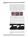
Supported Contexts
and Features
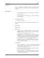
At the end of this section, we present two tables to help you
establish which of our Furnace plug-ins will work on your host
system, and how those plug-ins will work. The first table ( on
the following page) shows which plug-ins work in which contexts, and whether they require or support additional features
such as temporal caching or motion vectors. The second table
( on page 25) lists the contexts and features that are available
on each of our supported OFX host systems. To see whether a
plug-in will work on your host system, you should look in the
first table to see which contexts or features it requires, then
check the second table to see whether your host system is able
to provide these.
In these tables, a tick means something is supported, a cross
means it’s unsupported and a circle represents an optional feature, such as optional motion vector inputs or temporal caching
which is only needed when a particular control is switched on.
In the case of contexts, it is sufficient for your host to support
only one of the contexts a plug-in can work in in order for
that plug-in to work on your system. However, if the plugin supports temporal caching or motion vectors, in general it
will not work unless your host system supports them too. An
exception to this is if they are marked as optional features
(with an “o”), in which case they merely provide additional
functionality and the plug-in is able to work without them.
The Foundry
Furnace
24
INTRODUCTION
Furnace
General
Retimer
Vectors
Caching
Plug-in
Align
BlockTexture
ChannelRepair
ColourAlign
Contrast
Correlate
DeBlur
DeFlicker1
DeFlicker2
DeGrain
DeNoise
Depth
DirtRemoval
FrameRepair
Kronos
MatchGrade
MotionBlur
MotionMatch
MotionMatte
MotionSmooth
PixelTexture
ReGrain
RigRemoval
ScratchRepair
ShadowRemoval
SmartFill
SmartPlate
SmartZoom
Splicer
Steadiness
Tile
VectorConverter
VectorGenerator
VectorWarper
WireRemoval
Filter
Table 1.1 Plug-in Contexts and Features
»
«
»
»
»
«
«
»
»
O
«
«
»
»
»
»
«
»
»
»
«
»
»
»
»
»
«
»
O
»
«
«
»
»
»
«
«
»
»
«
«
»
»
»
»
«
»
»
»
»
«
«
»
O
»
«
«
»
O
»
«
«
»
O
»
«
«
»
»
»
«
«
«
O
»
»
«
»
»
»
«
«
»
O
»
»
«
»
»
»
«
«
»
»
O
«
«
»
O
»
«
«
»
»
»
«
«
»
»
»
«
«
»
»
»
«
»
»
»
»
«
»
»
»
O
«
«
»
»
»
«
«
«
»
«
«
»
»
»
«
»
«
»
»
O
«
»
»
»
»
«
»
»
»
»
»
«
»
«
»
«
«
»
«
»
»
«
»
«
»
«
«
»
»
»
The Foundry
25
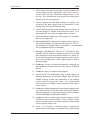
Other Foundry Products
Filter
Transition
Paint
Retimer
General
Vectors
Caching
Host
Nuke
Generator
Table 1.2 Host Contexts and Features
«
«
«
«
»
«
«
«
Other Foundry
Products
The Foundry is a leading developer of visual effects and image
processing technologies that boost productivity and workflow
in film and video post production. Its products include Furnace, Tinder, Tinderbox, Keylight, Forge and Anvil and run on
a variety of compositing platforms including Autodesk Flame,
Autodesk Flint, Autodesk Fire, Autodesk Inferno and Autodesk
Smoke, Shake, Avid|DS, After Effects, Combustion, and a variety of OFX compliant hosts. For the full list of products and
supported platforms see our web site http://www.thefoundry.
co.uk.
Tinder and Tinderbox are collections of image processing effects including blurs, distortion effects, background generators, colour tools, wipes, matte tools, paint effects, lens flares
and much more.
Anvil is a collection of colour correction and colour manipulation tools originally developed by First Art.
Keylight is an award winning blue/green screen keyer giving
results that look photographed not composited. The Keylight
algorithm was developed by the Computer Film Company who
were honoured with a technical achievement award for digital
compositing from the Academy of Motion Picture Arts and
Sciences.
Forge is a command line application that processes digital film
scans and automatically detects and corrects flecks of dirt,
dust and hair.
Nuke is an Academy Award® winning compositor. It has been
used to create extraordinary images on scores of feature films
including Flags of our Fathers, King Kong and The Day After
Tomorrow.
Visit The Foundry’s web site at http://www.thefoundry.co.uk
for further details.
The Foundry
Furnace
26
OVERVIEW
Overview
Great - so you’ve just downloaded, installed, and licensed up
your copy of Furnace, but where do you start? In this section
we’ll have a quick look at the various plug-ins, broken down by
what we would envision their application to be. Please bear
in mind, many of the tools offer much greater flexibility than
we can cover in this manual, so have a good play around with
them, and if you find a cool new use, or some tips or tricks
you want to share, then let us know in our support forum
(http://support.thefoundry.co.uk)!
Please select an overview from the list of sections below. When
you see an individual plug-in that you’d like to find out a little
more about, click on it and you will be taken to the plug-in
reference section for that tool. Grain Management | Retiming |
Dust Busting and Restoration | Clean Up, Touch Up and Removing In-Scene Objects | Stabilisation and Alignment | Arbitrary
Image Keying, Segmentation and Analysis | Grading | Clean Plate
Generation.
Grain Management
Amongst the most commonly used, and well known, of the Furnace plug-ins are the grain management tools. These three
plug-ins allow you to quickly remove and replicate grain patterns from both modern day fine-grained film stock and old,
degraded, archive material. So where (and why) would you
want to manage grain? In a whole host of different places; for
example:
• When comping (or even editing) two shots together it is
very obvious to the viewer when the grain characteristics
vary; take, for example, comping a moving Computer Generated (CG) element against a still frame: the background
still has static, unmoving grain, and the CG element will
have no grain at all. In this circumstance you’d replicate
the grain from the still frame and generate further frames
so that the grain appears to be in motion. This would
then be applied back against both the original still and
the CG element, helping create the illusion that it was all
shot in camera.
• When colour grading you’ll find that as you begin to push
the processing, the grain will be the first part of the
image that clips and otherwise introduces undesirable
artefacts. By removing it beforehand, then replicating it
on the finished shot you’ll save yourself a great deal of
trouble.
Furnace
The Foundry
27
Retiming
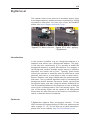
DeGrain is a fast (spatial) grain suppression tool, useful for
quickly cutting levels of grain on modern film stocks.
DeNoise is a temporal grain and noise removal tool, good for
everything from modern stock through to archival footage and
video noise.
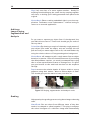
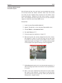
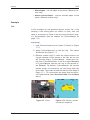
ReGrain allows you to reapply grain to a source clip. A number
of preset stocks are included, or you can sample a plate of your
choice and have ReGrain create a statistically identical moving
grain sample.
Figure 2.1 Grain management tools.
Retiming
Retiming is the process of altering the speed of a clip, to get
either slow or fast motion. Historically this was an ugly process
which introduced juddery or artefact-ridden output. By making
a best-guess about where objects move within a scene (motion
estimation) we are able to create frames between existing ones.
Once we know how these objects move we are also able to add
motion blur to these objects in motion as though it was shot
in-camera.
Kronos is Furnace’s retimer. It gives you full control over the
speed of playback of your clip and allows you to add motion
blur.
Correlate is for temporally aligning two passes over the same
scene. It retimes one clip to make it match another, reference
clip as closely as possible. MotionBlur allows you to add trueto-life motion blur to objects within a scene, without the added
complexity of the clip retiming controls.
Figure 2.2 Retiming tools.
The Foundry
Furnace
28
OVERVIEW
Dustbusting and
Restoration
Outside of the Grain Management mentioned earlier there are
a number of other issues which plague both modern day film
processing and archival restoration. Furnace contains a number of tools aimed at cutting down the amount of time you
spend painstakingly hand painting out such issues (and even
fix problems which are conventionally impossible to correct).
DirtRemoval repairs the objects that, when motion compensated, only appear on a single frame, and spatially appear to
be dirt. The result is an unsupervised dustbusting powerhouse.
DeFlicker1 and DeFlicker2 are two different algorithms for
dealing with film flicker from a variety of sources, be it poor
lighting ballast right through to bad cranking on a 1920s film
strip. Although there are no hard-and-fast rules - try using
DeFlicker with flicker that does not originate from the original
scene, e.g. ageing film, dust and chemical exposure. Give DeFlicker2 a go with in-scene flicker, poorly synchronised light
rigs, stray light etc. If one doesn’t quite give you the results
you are after, try the other!
FrameRepair generates replacement frames when original frames
are either fully or partially missing. Great for archive material,
damaged tapes or missing 3d renders.
ScratchRepair does just what you’d expect from the name!
Pop the widget where the scratch appears, and the defect will
disappear whilst the film grain and remaining image detail is
retained.
ChannelRepair rebuilds all or part of a single colour channel,
using the information from the other colour channels.
ColourAlign automatically realigns the RGB colour channels on
footage.
DeBlur Out of focus footage? Too much motion blur? Far more
than a simple sharpen filter, DeBlur intelligently reverses the
effects of blurring. You might like to try this in conjunction
with DeGrain if too much grain is introduced in the result.
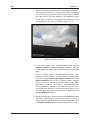
Steadiness provides automated 4-corner stabilisation of a sequence to help suppress any shakes or wobbles.
Furnace
The Foundry
29
Clean Up, Touch Up and Removing In-Scene Objects
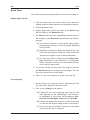
Figure 2.3 Restoration tools.
Clean Up, Touch
Up and Removing
In-Scene Objects
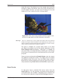
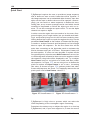
RigRemoval Got an object moving in relation to the background
(or vice versa), that you want to get rid of? RigRemoval scans
forwards and backwards within a sequence to find an area
where the background in question was unobstructed by the
object, and then copies that back into place. Great for unwanted traffic, people, and more.
WireRemoval That perennial paint favourite; cloning out, frameby-frame, the wires used for death defying stunts. Not anymore! WireRemoval has a variety of different repair types to
remove the wire automatically. ShadowRemoval Suppress an
excessive shadow using colour information from the shadow
itself.
MotionSmooth Boiling matte, stop-motion or filtered footage?
Try using MotionSmooth to blend motion compensated information together and help suppress such artefacts.
Figure 2.4 Clean-up tools.
Stabilisation and
Alignment
So you’ve got anything from a wobbly shot to a repair you want
to stick over the defect? These tools are the answer.
Steadiness Suppress wobbles in handheld footage or lock the
sequence position against a certain frame (great for when a
small shake hits an otherwise locked off shot), Steadiness requires no tracking markers to be specified.
The Foundry
Furnace
30
OVERVIEW
Align Lock one shot of a scene against another. Handy for
anything from doubling up the crowd size by comping together
two shots, to locking your freshly generated clean plate to the
original.
MotionMatch Planar tracking embedded right in your host application. Facilitates screen replacements - without having to
resort to an external application.
Arbitrary
Image Keying,
Segmentation and
Analysis
So you want to separate an object from it’s background, but
you didn’t blue-screen it? These tools should get you some of
the way there.
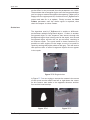
ColourMatte By drawing a couple of relatively rough mattes of
your object (one inside the object, and one outside) this will
pull out tricky-to-matte edges such as fur, hair and feathers by
using the relative colours of foreground against background.
MotionMatte will attempt to pull a rough matte from an object
based on its motion. Given the intensive amount of processing
that MotionMatte requires, we would recommend that trying
this on a few representative frames of footage first. If it gives
you good results on this small sub-set then run the sequence
through.
Depth extracts the relative depths of objects within a source
sequence using their motion. Want to reduce depth of field?
This should give you the matte to base your zblur on.
Figure 2.5 Keying, segmentation and analysis tools.
Grading
Help speed up the grading process using these image-enhancing
tools.
MatchGrade Got two shots from different times of day that
need to be comped or edited together? This plug-in analyses
the colour histogram of a reference image and automatically
Furnace
The Foundry
31
Texture Tools
applies the result to your source sequence. This allows sequences that were shot with subtly different lighting to have
the same ’look’.
Contrast Make that shot match the DoP’s memory of how it
looked on the day. This plug-in performs a spatially-dependant
contrast adjustment that makes for a punchier, more vibrant
image.
Figure 2.6 F_MatchGrade.
Texture Tools
Furnace also contains a number of tools designed for fixing
problem areas and generating plausible image textures from
small regions. These are useful for both image augmentation
and 3D texture artists.
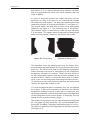
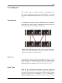
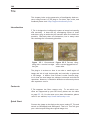
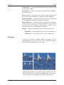
BlockTexture generates large-scale textures from a source image, such as distant crowds.
PixelTexture generates small-scale textures from a source image, which can be aligned with a rough colour image to match
a particular formation. Good for flowers, pebbles and so forth.
Tile creates tileable textures from a source image. One for the
3D guys, but also good for tiling brickwork, planking, etc.
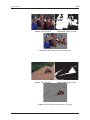
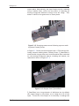
Figure 2.7 Crowd replication with F_BlockTexture.
Clean Plate
Generation
Aside from the texture tools, there are a number of other
plug-ins dedicated to helping you generate, and manipulate,
still frames.
The Foundry
Furnace
32
OVERVIEW
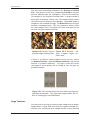
SmartFill is a hybrid texture tool, which in-paints a region
specified by you - generating a realistic looking fill from other
areas of the picture.
SmartPlate stitches together frames in a sequence to make one
high-resolution plate.
Splicer joins two images across an arbitrary path by finding the
most likely splice. Great on highly textured matte paintings.
Figure 2.8 Clean plate generation with F_SmartFill.
Furnace
The Foundry
33
Colour Space
in Furnace
Plug-ins
Introduction
Some of the algorithms in the Furnace tool set are sensitive to
the colour space of the source footage. If the footage is not
in the expected colour space, you may get poor results from
some of the plug-ins.
Furnace 4.2 (or later) on Nuke expects all footage to be in
Linear colour space.
NOTE : This behaviour changed with version 4.2, please see the
’Older Versions’ section of this chapter for more information.
Plug-ins most sensitive to colour space are :
• F_ChannelRepair
• F_Contrast
• F_DeBlur
• F_DeFlicker1
• F_DeGrain
• F_DeNoise
• F_Depth
• F_MatchGrade
• F_ReGrain
If you know the input to one of these colour-space sensitive
plug-ins is not Linear, you should use a Colorspace node either
side of the plug-in to convert to and from Linear for processing.
This should ensure optimal results.
Nuke converts footage to Linear upon import, so unless you
have changed the colour space in your Read nodes (or in the
node tree by using a Colorspace node before a Furnace plugin), your footage should already be Linear by the time it reaches
Furnace.
F_DeGrain, F_ReGrain and F_DeNoise are special cases, and
have additional pop-up menus to allow you to adjust the algorithm to get the best results when using footage that was
originally in another colour space. Please take a moment to
The Foundry
Furnace
34
COLOUR SPACE IN FURNACE PLUG-INS
read through the relevant chapters in this manual for these
plug-ins, to make sure you are aware of how they behave.
Older versions of
Furnace
Prior to version 4.2 of Furnace, some of the plug-ins were
tuned for sRGB footage. Nuke, by default, converts material
to Linear in the Read node. Because of this, you may not have
been getting the best results.
It is worth noting this when updating a script that uses older
versions of the Furnace plug-ins. You may see visual differences between the old and new versions of a plug-in with the
same settings. Generally, you should get better results with
the newer plug-ins as the algorithms are now tuned to the
colour space of the footage they get from Nuke.
With the exception of F_DeGrain, F_ReGrain and F_DeNoise, if
you need to recreate the look of one of the Furnace 4.1 plugins listed above with the newer plug-ins, wire in an sRGB (~2.2)
to Linear Colorspace node before, and its opposite after.
This might sound odd, but it is to re-establish the difference
between the source and the plug-in colour space that existed
before.
Furnace
The Foundry
35
Align
This chapter looks at how to register (line up) two separate but
similar shots with F_Align. For hints, tips, tricks, and feedback
please visit http://support.thefoundry.co.uk.
Introduction
F_Align uses Global Motion Estimation (GME) to calculate a four
corner pin so that each frame in one shot will be aligned with
the corresponding frame in a second reference shot. For more
of an overview of Global Motion Effects, and a description of
the common way of working many of these effects have, please
see the Global Motion Effects chapter on page 236.
F_Align is an Analysing Global Motion Effect, which can preanalyse a sequence for global motion and store the calculated
four corner pin as key framed parameters. This analysis is
done in the user interface of the plug-in and any keyframes
are used to align the clips in subsequent renders.
However, F_Align, unlike the other Analysing Global Motion
Effects, can still do something useful during render without
an analysis. If F_Align does not find a key framed pin on the
frame being rendered, it will calculate the inter-shot alignment
on the fly. The advantage of this is that you don’t have to
pre-analyse the complete sequence. The disadvantage is that
you don’t have direct access to the calculated corner pins and
any re-rendering will be significantly more expensive, as the
’on the fly’ calculations will have been lost and F_Align will have
to analyse again.
If at any stage you modify the effect in such a way to invalidate
the keyframed analysis (for example changing the accuracy
parameter), a warning will be posted and the effect will analyse
on-the-fly during render, ignoring the keyed analysis.
The Analysis Region is used to control which section of the
Reference frame is being matched to each Source frame. Typically, leaving the region at its default is good enough; however,
a heavy mismatch in foreground detail may make it necessary
to change the region to a section that is shared between shots.
Contexts
F_Align supports the general context only. To see which contexts are supported by your OFX host, please see the table
on page 25. Or, for the most up-to-date information, please
refer to our website, http://www.thefoundry.co.uk.
The Foundry
Furnace
36
ALIGN
Quick Start
This section gives a very brief outline of how to use the plug-in.
Analysing On The Fly
1. Find two shots that are of the same scene, but have
slightly different camera motion and foreground objects.
2. Load both these shots.
3. Apply F_Align using one of the shots as the Source clip
and the other as the Reference clip.
4. The Source will have been immediately repositioned so
that it aligns to the Reference shot without any need for
analysis.
(a) You will see a banner in the overlay saying ’Note:
the keyframed analysis is currently invalid. Analysing
during render.’
(b) depending on the exact difference between the two
shots you may need to enable the ’scale’ and/or the
’perspective’ toggles to get a decent alignment,
(c) you may also need to reposition the Analysis Region depending on the differences in foreground
detail. However, leaving it at the default position
works well for most shots.
5. To see how closely the two clips have aligned, subtract
the Reference input to F_Align from its output. This will
show you where the two clips differ.
6. That’s it. You can now play or render the result out.
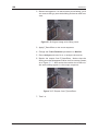
Pre-Analysing
1. Use the same two shots you used in ’Analysing On The
Fly’, and load F_Align with them as before.
2. Click on the ’Analyse’ push button.
(a) F_Align will now start analysing each frame in the
shot, figuring out the smoothing pin and writing it
as keyframes to the corner pin parameters, Bottom Left, Bottom Right, Top Left and Top Right.
(b) F_Align will update the time-line at each frame and
you will see the aligned image render in the output.
(c) If you interrupt the analysis, the pins it has keyed
until that point will be retained.
Furnace
The Foundry
37
Inputs
3. Play or scrub through the aligned frames. The rendering
will be faster as F_Align will no longer need to analyse on
the fly.
(a) However, if you scrub to a frame where a corner
pin has not been keyed, F_Align will re-analyse that
frame on the fly.
4. That’s it! You can now play or render the result out.
Inputs
F_Align has two input clips; the Source (Src) input is moved so
that each frame matches the Reference (Ref) input frame.
Parameters
Align shares all the Analysing Global Motion Effect parameters
which are described in the Global Motion Effects chapter on
page 236.
Analysis Range - in F_Align has one further option :
• Current Frame - the analysis occurs only on the current
frame. This is useful for correcting any errors that may
have occurred while analysing the entire clip.
Examples
The images for the following examples can be downloaded from
our web site. For more information, please see the Example
Images section on page 17.
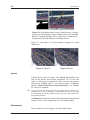
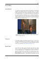
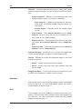
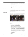
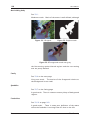
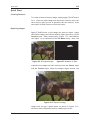
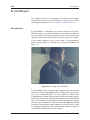
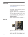
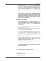
Aligning Belle
In this example we make use of the two clips ’belleCentre’ and
’belleLeft’ and align one to the other.
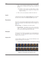
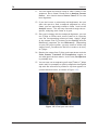
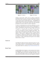
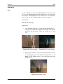
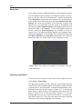
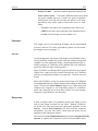
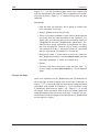
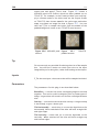
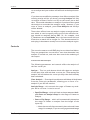
1. Load the two clips belleLeft.####.tif and belleCentre.####.tif,
Figure 4.1 The belleLeft and belleCentre clips.
The Foundry
Furnace
38
ALIGN
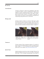
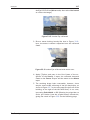
2. Apply F_Align with belleLeft as the Source clip, and belleCentre as the Reference clip,
(a) belleLeft will immediately be aligned with belleCentre, you will see the image jump immediately to the
left and slightly up
3. Disable the Rotation toggle.
(a) due to the nature of this shot (the back drop undulates slightly and the slight amount of perspective
difference) a better alignment is achieved if we disable rotations
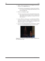
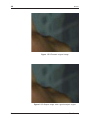
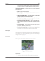
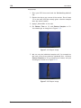
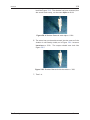
4. If your OFX host allows you, try subtracting belleCentre from the output of F_Align. This will show you how
well the two clips have been aligned; an example of the
difference image is shown in Figure 4.2.
5. You now have aligned belleLeft with bellCentre. Render
her out, or scrub through the shot to see the results.
Figure 4.2 The difference between the aligned ’belleLeft’ and
the ’belleCentre’ clips.
Furnace
The Foundry
39
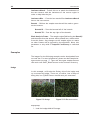
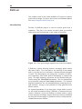
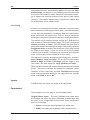
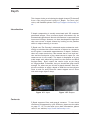
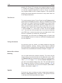
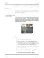
BlockTexture
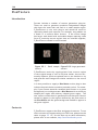
Introduction
Furnace includes a number of texture generation plug-ins.
These are used to create resolution independent images that
have the same look and feel as a small sample region from a
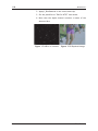
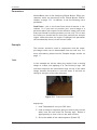
source image. F_BlockTexture is one such plug-in and should
be used for replicating fairly large scale textures. By that we
mean textures that contain shapes rather than more uniform
textures that would be suited to F_PixelTexture.
F_BlockTexture works by taking blocks of data from the original
image and rearranging them in a random fashion in such a
way that the joins between the blocks are invisible and look
plausible. The size of the blocks depends on the scale of
the texture being replicated and the Overlap of the blocks
controls how well the joins between blocks are hidden. This
plug-in tends to generate the best results on more natural
looking textures, for example, leaves blowing in the wind or
even crowds of people.
F_BlockTexture also has the ability to generate temporally consistent frames of textures but only over small motion ranges.
Note that network rendering is not possible with F_BlockTexture
when Temporal Consistency is switched on.
Figure 5.1 Original image Figure 5.2 BlockTexture used
showing the river Thames in to generate moving water
London.
texture.
Contexts
F_BlockTexture supports the filter and general contexts. To see
which contexts are supported by your OFX host, please see the
table on page 25. Or, for the most up-to-date information,
please refer to our website, http://www.thefoundry.co.uk.
The Foundry
Furnace
40
BLOCKTEXTURE
Quick Start
In the filter context, F_BlockTexture has a single input, the
Source clip. In the general context it has additional optional
inputs: three Texture inputs and a Matte input. The Texture
inputs should be the image or images whose texture you wish
to sample. The Source input will have the generated texture
applied to it. If no Texture inputs are connected, or the effect
is applied in a filter context, the texture is both sampled from
and applied to the Source. The Matte is an optional input that
allows you to specify a region in the Source image that you
wish to fill with the new texture. This region can be blended
with the original image to produce a seamless fill.
Figure 5.3 The original image is shown on the left. This
image has recognisable shapes and is more suited to
F_BlockTexture. F_BlockTexture has been used to generate
the image in the middle which shows good shape retention.
For comparison, F_PixelTexture has been used on the right.
If you have more than one region in the matte, they must be
connected together by a thin line. The example below shows
the matte used to add crowds to two new sections of a football
stadium. Note that the regions need to be joined or only one
region will be filled.
Figure 5.4 Incorrect.
Figure 5.5 Correct.
After adding the texture inputs use the on screen Bounds
selection tool to define the area that will be sampled. A larger
source region will mean less noticeable repetitiveness in the
new texture.
Furnace
The Foundry
41
Quick Start
Alternatively, if you have supplied a matte of the region you
wish to fill, selecting Avoid Matte will copy texture from any
regions not specified by the matte. Make sure Fill Screen is
switched off though.
If a matte input is used, texture will now be copied into the
Source image but only where there is full alpha in the matte. If
there is no matte, switching on Fill Screen will generate a complete frame of new texture. Adjust Block Size to find a suitable
sized building block to generate the new texture. Overlap determines the amount adjacent blocks are overlapped. A greater
overlap gives a better chance of hiding the edge join. If the
edges are still visible increasing Blend Size will blur the join,
but too much blurring will result in a noticeable soft edge to
the blocks. Increasing Samples will increase the quality of the
fit between blocks, but at the expense of processing time. The
whole process is seeded by a random number so changing the
Seed will give you alternative texture fills, some of which may
be more pleasing than others.
If you are using a matte to specify the region to be filled,
Path Width specifies the quality of the join between the texture
region and the source image. Similarly Edge Blend specifies
the extent to which this join is blurred. If there is luminance
change across the region being filled then switching on Luminance Match will attempt to align the luminance between the
new region and original image. Luminance Blur controls the
extent of this matching process.
Finally, if you are attempting to generate temporal textures
switch on Temporal Consistency before rendering an output
sequence. This will ensure the new texture is generated in a
consistent manner on successive frames.
Crowds
F_BlockTexture can also be used for crowd replication. In Figure
5.6, the original image is a locked off shot of a small crowd
filling only part of a stadium. During the sequence the crowd
stand up and wave flags. By drawing a matte to specifiy where
we want to put new crowd, F_BlockTexture can be used to
split up the crowd into plausible jigsaw pieces and reassemble
them in the locations defined by the matte. This plug-in works
temporally, so that the new crowd also stand up but at different
times to the original.
Note
The Foundry
You should note that with Temporal Consistency switched on the sample
texture will be taken from the sample region on the start frame only. Any
changes to the size or position of the sample region over the sequence
will be ignored by the algorithm. The algorithm also assumes the matte is
unchanging.
Furnace
42
BLOCKTEXTURE
Figure 5.6 Crowd Replication using F_BlockTexture. Images
courtesy of The Moving Picture Company from the film Mike
Bassett: England Manager 2001 Film Council, Hallmark Entertainment and Entertainment Film Distributors
Figure 5.7 and Figure 5.8 show another example of crowd
replication.
Figure 5.7 Before.
Figure 5.8 After.
Inputs
F_BlockTexture has five inputs. The Source (Src) defines the
size of the texture that will be generated. If it is the only
input, or the plug-in is applied in a filter context, the texture
will also be sampled from it. The texture inputs - Texture1
(Tex1), Texture2 (Tex2) and Texture3 (Tex3) - are sampled
for texture if supplied.
Tip
If you have just one image from which to sample texture, apply this as
Texture1, then rotate it and apply it as Texture2, then scale it and apply
it as Texture3. By providing additional inputs you will reduce repetition in
the generated texture.
The Matte defines the area that will be filled with the generated
texture. This is then composited over the Source input.
Parameters
The parameters for this plug-in are described below.
Furnace
The Foundry
43
Parameters
Fill - defines the area to fill with the generated texture
• Full Frame - fill the whole of the destination image, which
will be the same size as the source image.
• Src Alpha - fill the region defined by the alpha of the
source.
• Src Inverted Alpha - fill the region defined by the inverted
alpha of the source.
• Matte Luminance - fill the region defined by the luminance of the matte. (General context only)
• Matte Alpha - fill the region defined by the alpha of the
matte. (General context only)
• Matte Inverted Luminance - fill the region defined by the
inverted luminance of the matte. (General context only)
• Matte Inverted Alpha - fill the region defined by the
inverted alpha of the matte. (General context only)
Block Size - The size of the building blocks used to make the
new texture.
Overlap - The amount the building blocks are to overlap. A
larger overlap is more likely to generate a better edge join.
Blend Size - The amount of blur at the edges between building
blocks. A small amount is good to help hide the edges on some
images but too much will result in an obvious softness.
Samples - The number of different blocks that are tried before
choosing the best match. The higher the number the better the
match but the longer the render time.
Seed - The random number used to start the texture generation process. Select another seed to see a different texture
pattern.
Path Width - Sets the width of the join between the source
image and the new texture. The larger the path the better the
quality of join.
Edge Blend - The amount of blur between the source image
and the new texture. A small amount is good to help hide the
edges but too much will result in an obvious softness.
Avoid Matte - Switch this on to sample texture from the region that is not specified by the matte as opposed to the region
specified by the Bounds. (General context only)
Temporal Consistency - Switch this on to force temporal consistency in the new texture between successive frames.
The Foundry
Furnace
44
BLOCKTEXTURE
Luminance Match - Switch this on to match the luminance of
the new texture with the luminance of the source region in
order to help hide the join.
Luminance Blur - Controls how much effect Luminance Match
has on the new texture.
Bounds - Defines the sample area that will be used to generate the texture.
Bounds BL - Sets the bottom left of the bounds.
Bounds TR - Sets the top right of the bounds.
Block Analysis Frame - The sample region (defined by the Bounds)
and the matte that the texture will be pasted into, will be taken
from this frame. Any changes to the sample region or matte
on other frames will be ignored by the algorithm. Note, this
parameter is only valid if Temporal Consistency is switched
on.
Examples
The images for the following example can be downloaded from
our web site. For more information, please see the Example Images section on page 17. There are also some sample textures
that work well with F_BlockTexture in the Textures directory.
Hedge
In this example, we’ll take the flickery clip of the hedge and
try to extend its height. There are, of course, lots of ways of
doing this, but F_BlockTexture should save you some time.
Figure 5.9 Hedge.
Figure 5.10 Reconstruction.
Step by Step
1. Load the hedge.####.tif footage.
Furnace
The Foundry
45
Examples
2. Make a rough matte of the top of the hedge. This will
define the area we wish to replace with generated texture.
Figure 5.11 Rough Hedge Matte
3. Apply F_BlockTexture to the hedge clip and use the matte
you have made as the Matte input.
4. Position the box sample area. The image in this box will
be sampled and used to generate new texture.
Figure 5.12 Sample Box.
5. Make sure Temporal Consistency is switched on and
render.
The Foundry
Furnace
46
CHANNELREPAIR
ChannelRepair
This chapter looks at repairing single colour channel damage
using Furnace’s plug-in F_ChannelRepair. For hints, tips, tricks,
and feedback please visit http://support.thefoundry.co.uk.
Introduction
Occasionally damage can occur in only one or two colour channels in an image, for example, a scratch may be only two channels deep or chemical damage may only affect the top layer of
the film. In these cases F_ChannelRepair can be used to repair
the damaged channel(s) by using information from the other
colour channels.
Figure 6.1 Blue channel damage.
Figure 6.2 Undamaged green channel.
The first spatial repair algorithm, Blend, tries to match the
statistics of the reference channel to the undamaged area of
the damaged channel. It then simply blends the matched pixels
of the reference channel to fix the damage. The second algorithm, ReMatch, is more complex and attempts to adjust the
local statistics of the proposed Blend repair to those in the
Furnace
The Foundry
Contexts
47
undamaged area. It is entirely dependent on the footage as to
which algorithm gives the best result.
It is possible to tune the ReMatch algorithm to improve the
repair quality. F_ChannelRepair uses a block based approach
to model the damage in the image. The clean and damaged
channels are split into multiple blocks of size Block Size. We
then try and modify the local statistics of the damaged block
to make it equal to the local statistics of the clean block. In
practice, if there is motion in the sequence the pixels in the
two blocks will not be the same, which will result in incorrect
estimation of the local statistics. To minimise this effect, when
the image is divided into blocks they are overlapped by a small
region. To this region we apply the statistics calculated for
both adjacent blocks. If the results from these two blocks are
not consistent we assume that the parameters have been calculated incorrectly due to motion and we discard them both,
replacing them with the global statistics for the whole damaged region. The criterion for discarding parameters is set by
Motion Threshold. So, if you think the damage is only in parts
of the image that are static, it is quite safe to increase this
value. If there is little information in the block, for example
in a plain area, it is difficult to obtain reliable estimates for
the statistics. We check for this by discarding the parameters
for any blocks with a variance below Weight Threshold. Having obtained a reliable set of parameters for each block these
are then smoothed using a combing technique. The number of
smoothing iterations is set by Smoothing Iterations.
Contexts
F_ChannelRepair supports the filter and general contexts. To
see which contexts are supported by your OFX host, please see
the table on page 25. Or, for the most up-to-date information,
please refer to our website, http://www.thefoundry.co.uk .
Quick Start
Connect the damaged frame or sequence to the first (Source)
input of F_ChannelRepair. If your host allows multiple inputs
to F_ChannelRepair, create a matte of the damaged region and
connect it to the second (Matte) input. Set Repair Channel
to the damaged channel and Use Channel to the channel from
which you wish to take information to make the repair. Set the
Match Method to Blend.
Adjust Weight Threshold, Block Size, Motion Threshold and
Smoothing Iterations as described in the parameter section
to tune the output if necessary.
The Foundry
Furnace
48
CHANNELREPAIR
Figure 6.3 Repaired image.
Inputs
When used as a filter, F_ChannelRepair has a single input: the
damaged frame or sequence.
When used in the general context, the Source (Src) input contains the damaged frame or sequence. The Matte input is
optional. If supplied this should contain a frame or sequence
that specifies where the damage occurs. Use the Matte Component parameter to define which areas are to be repaired; by
default the Luminance of the matte is used.
Parameters
The parameters for this plug-in are described below.
Repair - defines the area to repair.
• Full Frame - repair the whole of the source image.
• Source Alpha - repair the region defined by the alpha of
the Source.
• Source Inverted Alpha - repair the region defined by the
inverted alpha of the Source.
• Matte Luminance - repair the region defined by the luminance of the matte. (General context only)
• Matte Alpha - repair the region defined by the alpha of
the matte. (General context only)
• Matte Inverted Luminance - repair the region defined
by the inverted luminance of the matte. (General context
only)
• Matte Inverted Alpha - repair the region defined by the
inverted alpha of the matte. (General context only)
Furnace
The Foundry
Parameters
49
Use Channel - selects the undamaged channel of the image
from which to take information to make the repair.
Repair Channel - Selects the damaged channel of the image
to be repaired.
Match Method - There are two possible techniques to take
information from one channel and apply it to another.
• Blend - Feathers the duplicated pixels from Use Channel
into Repair Channel.
• ReMatch - Attempts to make the local statistics between
Use Channel and Repair Channel identical.
The following four parameters apply only to the ReMatch
method.
Weight Threshold - Sets the threshold value for plain areas
above which blocks are discarded due to the lack of reliable
data. If your results are poor, it’s worth decreasing this value.
Block Size - Sets the size of the blocks that are analysed.
Smaller blocks will allow more complex damage to be modeled
but will produce less accurate and robust results, and will take
longer to render.
Motion Threshold - Sets the threshold value above which localised damage is abandoned because of motion in the frame.
If your results are poor and you can see that there is little motion in the sequence, you should increase this value. Setting
the motion threshold to 1 will turn off localized damage repair
for all moving objects and apply a global algorithm to reduce
the damage.
Smoothing Iterations - Sets the number of times the damage
parameters are smoothed between blocks.
The Foundry
Furnace
50
COLOURALIGN
ColourAlign
This chapter looks at colour channel registration (alignment)
using Furnace’s plug-in F_ColourAlign. For hints, tips, tricks,
and feedback please visit http://support.thefoundry.co.uk.
Introduction
Occasionally due to damage to the film or errors in the scanning process the red, green and blue channels can become
misaligned. F_ColourAlign will automatically repair this damage by aligning the channels with a reference channel of your
choice.
This type of colour damage is often particularly obvious when
restoring old three-strip Technicolour® type footage.
Figure 7.1 Mis-aligned.
Figure 7.2 Aligned.
Contexts
F_ColourAlign supports the filter and general contexts. For details of which contexts are supported by your OFX host, please
see the table on page 25. Or, for the most up-to-date information, please refer to our website, http://www.thefoundry.co.uk
.
Quick Start
Connect the damaged frame or sequence to F_ColourAlign. Select the Reference channel that you wish the other channels
to be aligned to and view the result.
Normally the transformation causing the misalignment can be
modelled by a simple translation. In more complex situations it
may be necessary to calculate rotation, scale and perspective
changes by activating the relevant controls.
Furnace
The Foundry
51
Inputs
The quality of the interpolation of the misaligned channels can
be modified by adjusting the Filtering parameter. Low is the
quickest but the image might look soft, aliased or discretised.
Medium uses a bilinear filter, and high uses a sinc filter for the
best results but at the expense of speed.
If the misaligned channels are noisy, it will be more difficult
to estimate the transformation required to align them and this
may adversely affect the results. The Noise controls refer to
an optional median filter that can be applied per channel to
reduce the noise on the reference images used internally to do
the alignment. This can improve the results of the alignment
and will not affect the noise on the output image.
Inputs
When working as a filter, F_ColourAlign has a single input:
the sequence to be aligned. When working in the general
context, it has an additional optional input. This is a Reference
(Ref) clip that can be used to calculate the transformation
to apply to the first clip. This means a denoised version of
the input can be used to calculate the transformation to be
applied to the original clip. (Although the plug-in has its own
noise reduction controls, better results can often be obtained
by using a more advanced noise reduction technique, such as
Furnace’s F_DeNoise or F_DeGrain.)
Parameters
The parameters for this plug-in are described below.
Reference - The colour channel to be used as a reference. The
other colour channels will be aligned to this channel.
Rotate - Switch this on if the misalignment transformation
between the colour channels contains a rotation.
Translate - Switch this on if the misalignment between the
colour channels contains a translation.
Filtering - Sets the filtering quality
• Low - low quality but quick to render
• Medium - uses a bilinear filter. This gives good results
and is quicker to render than high filtering
• High - uses a sinc filter to interpolate pixels giving a
sharper repair. This gives the best results but takes longer
to process.
The Foundry
Furnace
52
COLOURALIGN
Noise - The parameters to control denoising of the images
before alignment. Noise can sometimes cause incorrect results
in channel registration. This median is applied to the reference
clip so that the output will not have the median applied.
Noise Red - The median size used to denoise the red
channel internally.
Noise Green - The median size used to denoise the green
channel internally.
Noise Blue - The median size used to denoise the blue
channel internally.
Sample Region - The region of the image that the plug-in attempts to align between the colour channels.
Sample Region BL - The bottom left of the sample region.
Sample Region TR - The top right of the sample region.
Advanced - The lesser used refinement controls.
Scale - Switch this on if there are changes in scale between the colour channels.
Perspective - Switch this on if there are changes in perspective between the colour channels.
Accuracy - It is rarely necessary to find the optimum
transform for all pixels and so, to speed up the process,
the accuracy can be reduced. High values will increase the
processing time but may give you better alignment.
Examples
The footage used in the following example can be downloaded
from our website. For more information, please see the Example Images section on page 17.
BelleColourAlign
1. Load BelleColourAlign.####.tif, and apply F_ColourAlign.
The result is poor on the default settings, as in Figure 7.3
on the next page, but we can fix that.
2. Look at the blue channel - there is a large amount of
noise preventing the blue channel from aligning. Set the
Noise Blue parameter to 1 in order to get rid of some of
this noise for analysis, and you should get a result as in
Figure 7.4. If your host supports multiple inputs you may
wish to use an external noise rejection algorithm. To do
Furnace
The Foundry
53
Examples
Figure 7.3 Poor result, caused by noise in the blue channel.
so, process the clip through the external noise rejection
algorithm and then apply the result as the Reference
clip.
Figure 7.4 Better result, after reducing the blue noise.
3. Render the entire sequence and look at the results.
The Foundry
Furnace
54
COLOURMATTE
ColourMatte
This chapter looks at keying off arbitrary backgrounds using
Furnace’s plug-in F_ColourMatte. For hints, tips, tricks, and
feedback please visit http://support.thefoundry.co.uk.
Introduction
F_ColourMatte is designed to help an artist pull a matte of an
object that has a soft edge, for example, fur, hair, or motion
blurred objects that can appear on top of any background. The
artist supplies a set of mattes to define the foreground object
to be keyed, and F_ColourMatte will refine these mattes to an
accurate alpha.
Background
The image in Figure 8.1 is a typical example of an input to
F_ColourMatte. The aim is to accurately build an alpha channel
of the man in the foreground.
Figure 8.1 ColourMatte can be used to extract a matte from
images like this.
Consider the compositing equation:
C=alpha*F+(1-alpha)*B
This describes how a pixel of rgb value C is composed of a
foreground colour F, scaled by alpha, and background colour
B, scaled by 1-alpha. The aim of this plug-in is to deduce
values for F,B and alpha, given C. Obviously this is a very tricky
problem as for every three known variables (the red, green, and
Furnace
The Foundry
55
Background
blue values of C), we must estimate seven unknown variables
(the red, green and blue values of F and B, together with the
value of alpha).
In order to solve this problem we require the artist to first
generate a tri-map. A tri-map is a set of mattes that divides
the image into three regions. The first region marks part of the
image that is known to be foreground (alpha=1), see Figure 8.2.
The second defines the part that is known to be background
(alpha=0), see Figure 8.3. The remaining part of the picture,
the unknown region, is the area over which we must calculate
F, B and alpha. The tighter these foreground and background
mattes can be painted, the better, and faster, the results.
Figure 8.2 Foreground.
Figure 8.3 Background.
The algorithm works by taking pixels from the known foreground and background regions and trying them at the current
pixel site. The colours that best fit the compositing equation
whilst ensuring some form of smoothness to the foreground,
background and alpha are chosen. These are then forced to
fit the compositing equation and the process repeated in an
iterative manner. Hence, it should be noted that if a colour
close to the correct foreground and background does not exist anywhere nearby in the known foreground and background
regions, the algorithm is likely to fail.
If a clean background plate is available, this can be supplied
as an input. In this case the number of unknowns are reduced
dramatically leading to better results but it is important that
the background plate is almost identical in colour and alignment
to the background of the source image. If necessary, the clip
should first be registered using F_Align.
The outputs of the plug-in are the unpremultiplied foreground
(F), the alpha (a), and, optionally, the unpremultiplied background (B). Providing F and alpha separately means it is a trivial matter to composite the foreground into a different picture
(see Figure 8.4).
The Foundry
Furnace
56
COLOURMATTE
Figure 8.4 Foreground composited over mid grey using matte
generated from F_ColourMatte.
Contexts
F_ColourMatte works in the general context only. For details
of which features and contexts are supported by your OFX
host, please see the table on page 25. Or, for the most upto-date information, please refer to our website, http://www.
thefoundry.co.uk .
Quick Start
Connect the source frame to the Source input. You will need
to supply mattes of the known foreground and background
areas to the Foreground Mask and Background Mask inputs
respectively.
The unpremultiplied foreground of the source frame should be
displayed. View the alpha channel to see the alpha matte of
the image. Try compositing this over a plain background to see
the quality of the segmentation.
Try different Colour Selection and Refinement algorithms to
improve the results. Also try increasing the number of Refinement Passes.
Ideally the Foreground Mask and Background Mask input
mattes should be drawn as tightly as possible around the unknown region. If they are fairly loose, it is worth running a
few Matte Optimiser passes to refine the mattes before calculation of the alpha. This should dramatically speed up the
algorithm. To do this, increase the Levels parameter.
Furnace
The Foundry
57
Inputs
Inputs
F_ColourMatte has four inputs. Source (Src) is the source
image, Foreground Mask (Fg) is a matte specifying those
regions which are definitely foreground pixels (alpha=1) and
Background Mask (Bg) is a matte specifying those regions
which are definitely background pixels (alpha=0). Optionally,
a clean background plate, Known Background (KBg), can also
be supplied.
Parameters
The parameters for this plug-in are described below.
Render - displays either the unpremultiplied foreground or the
background. The alpha is automatically associated with the
foreground.
• Extracted Foreground
• Extracted Background
Colour Selection - three possible techniques are used to choose
initial guesses of the foreground and background colours at an
unknown pixel
• Use Similar Colours forces a foreground colour to be
chosen that is similar to the combined colour C.
• Use Any Colours chooses a pixel at random from the
nearby foreground region for the unknown foreground
colour and a pixel at random from the nearby background
region for the unknown background colour.
• Use Diffuse Colours chooses pixels for the foreground
and background by diffusing the colours in from the known
foreground and background regions into the unknown region. This results in much smoother more consistent foreground and background colour guesses.
Refinement - having chosen an initial guess for the foreground and background colours there are two possible refinement methods. Error Minimising is more suitable for more
complex, rapidly changing alpha’s and Detail Matching is better
suited to smoother alphas.
• Error Minimising takes the initial values for F and B and
solves the compositing equation for alpha. An iterative
process of refinement follows whereby the colours are
modified in an attempt to get a better fit to the compositing equation whilst ensuring the foreground, background
and alpha remain consistent and edges in the alpha correspond to edges in the original image.
The Foundry
Furnace
58
COLOURMATTE
• Detail Matching takes the initial values for F and B and
forces them to fit a system of equations that combines
knowledge of both the compositing equation and structure in the image.
Refinement Passes - the number of refinement iterations that
take place. The greater the number, the better the output but
the longer the processing time.
Edge Error Weighting - how strictly edges in the alpha must
correspond to edges in the input.
Matte Optimise - if the known foreground and background
mattes are quite loose it is possible to use the matte optimiser
to try and refine these mattes before the algorithm spends
a large amount of time calculating alpha. This is achieved by
running a number of crude passes of the algorithm that attempt
to shrink the region of unknown alpha. At each pass any pixel
with an alpha value of within Levels Threshold of 0 or 1 is set
to 0 and 1 respectively.
Levels - the number of iterations of matte optimisation.
More levels will take longer but should produce tighter
results.
Levels Threshold - any pixel with an alpha value within
Levels Threshold of 0 and 1 is set to 0 and 1. Increasing
Levels Threshold will shrink the size of the unknown region
faster but is more likely to incorrectly set a soft alpha to
0 or 1.
Fg Component - which component of the Foreground Mask
clip to use.
• Luminance - use the luminance of the Foreground Mask
clip.
• Inverted Luminance - use the inverse of the luminance
of the of the Foreground Mask clip.
• Alpha - use the alpha channel of the Foreground Mask
clip.
• Inverted Alpha - use the inverse of the alpha channel of
the Foreground Mask clip.
Bg Component - which component of the Background Mask
clip to use.
• Luminance - use the luminance of the Background Mask
clip.
• Inverted Luminance - use the inverse of the luminance
of the of the Background Mask clip.
Furnace
The Foundry
Parameters
59
• Alpha - use the alpha channel of the Background Mask
clip.
• Inverted Alpha - use the inverse of the alpha channel of
the Background Mask clip.
The Foundry
Furnace
60
CONTRAST
Contrast
This chapter looks at image enhancement using F_Contrast.
For hints, tips, tricks, and feedback please visit http://support.
thefoundry.co.uk.
Introduction
F_Contrast allows the user to extract hidden details from dark
and bright areas of an image. Based on the adaptive contrast
enhancement algorithm in Apical’s Iridix product, F_Contrast
boosts dark areas to give more balanced, memory-true images.
Most contrast enhancement (dynamic range compression) technologies are fixed and uniform, for example gamma correction.
Figure 9.1 Original with unbalanced contrast.
Figure 9.2 Original washed out with gamma correction.
However, F_Contrast’s algorithm is retina-morphic. Retinamorphic contrast enhancement behaves like the human visual
Furnace
The Foundry
61
Contexts
system; it is adaptive, and it is spatially-varying. In other
words, it automatically calculates a different curve transformation for each pixel in the image, based on an analysis of the
scene’s content.
Figure 9.3 Original corrected with F_Contrast.
As a result, images processed using this technology are continually in balance across the entire image. Contrast and detail
are preserved or enhanced both in dark and bright areas and
true colour is preserved.
Because the processing mimics the human visual system, the
images which are produced automatically look natural, without
the need for complex calibration or parameterisation.
F_Contrast’s algorithm is often employed “on-chip” in modern cameras. By shooting without this switched on, you can
get flatter images which are more suitable for effects work.
F_Contrast allows you to boost the impact of these flat images
to match what was seen on set.
Contexts
F_Contrast supports the filter context only. To see which contexts are supported by your OFX host, please see the table
on page 25. Or, for the most up-to-date information, please
refer to our website, http://www.thefoundry.co.uk
Quick Start
Apply F_Contrast to the sequence you wish to enhance. It
will immediately attempt to balance the contrast. Control the
amount of enhancement using the Strength parameter. The
ability of the plug-in to transform different areas of the image
and the strength of the balance between processing dark and
The Foundry
Furnace
62
CONTRAST
light areas can be controlled by the other parameters Variance
and Asymmetry respectively.
Inputs
F_Contrast has one input. This input, Source (Src), contains
the sequence to enhance.
Parameters
The parameters for this plug-in are described below.
Strength - Controls the amount of dynamic range compression performed by Iridix. This can be made larger or smaller
depending on the characteristics of the display and the quality of the source image. The lower the dynamic range of the
display relative to the source, the larger should be this setting.
Variance - Affects the sensitivity of the transform to different
areas of the image and can be increased in order to emphasise
small regions (e.g. faces). If this parameter is set to zero, the
transform becomes spatially uniform.
Asymmetry - Affects the strength of the transform in dark
areas relative to bright areas of the image. The larger this parameter, the more the transform concentrates on the dark parts
of the image. If set to around 80 and above, the transform
concentrates almost completely on the dark areas, meaning
that e.g. sky contrast is unaffected by the processing.
Noise Suppression - Affects the strength of the transformation in very dark areas to prevent sensor or compression noise
from becoming visible in the output image. A large value
strongly restricts the transform, and should be used if source
images are very noisy. The lower the value, the larger the enhancement capability for dark areas. This parameter can be set
to a single value for all images, or to different values according
to shooting conditions (exposure level, ISO speed, degree of
source file JPEG compression).
Furnace
The Foundry
63
Correlate
Introduction
F_Correlate is targeted specifically at the problem of temporally
aligning two separate passes of the same scene. It is often
used in conjunction with F_Align, which aligns two clips spatially
(see Align on page 35). A source clip passed to F_Correlate will
be retimed to match a reference clip; if a spatial misalignment
remains between the two clips after this has been done, the
output from F_Correlate can be passed to F_Align to be spatially
aligned with the reference clip.
Figure 10.1 F_Correlate, followed by F_Align, used to match
move two clips into one.
Contexts
F_Correlate supports the general context only. To see which
contexts are supported by your OFX host, please see the table
on page 25. Or, for the most up-to-date information, please
refer to our website, http://www.thefoundry.co.uk.
Quick Start
You’ll need two clips, each a separate pass over the same
scene. The first clip, Source, will be retimed to match the
second, Reference, clip. The Reference clip will be left alone.
Apply F_Correlate to your two clips. As a starting point, press
Reset Analysis to set up the default timing curve for the
Source Frame parameter - this aligns the beginning and end
The Foundry
Furnace
64
CORRELATE
points of the two clips and assumes a linear relationship in
between. Now go to the first frame of the reference sequence
and select Show: Mix to assess how well the two clips are
aligned at this point. If they appear perfectly aligned already,
move to another frame of the sequence where there is a visible disparity. Press Analyse Current Frame to search for
a better temporal match. The position of the closest frame
found will be keyed into the Source Frame parameter. If the
results of this analysis look poor, your temporal search range
is probably too small. If so, you can either just press Analyse Current Frame again to perform a new search around the
closest frame found last time, or try again with an increased
Temporal Search Range. Increasing the search range should
speed up this process if you expect the closest frame to be
further from the Source Frame than the current search range
allows.
Rather than aligning frames manually, you can also press the
Analyse button to analyse all frames within the Analysis
Range in one go. By default, the plug-in is set to analyse
the full length of the Reference clip, finding the closest source
frame for each of the reference frames. However, if you wish
you can change the Analysis Range by choosing Specified
Range and adjusting Analysis Start and Analysis Stop. Once
the sequences have been analysed, render the output from
F_Correlate to see the retimed result. Again, you might need to
repeat the analysis if your temporal search range is too small.
Inputs
F_Correlate has at least four inputs. The first input, Source
(Src), will be the sequence which is retimed and output during
processing. The second input, Reference (Ref), is the clip we
want to match the Source clip to. The third input, Reference
Mask (RefMask), can be used to specify the region of the
reference frame to use during analysis. Note that the mask
is there to define the regions of the image to use, not those
to ignore. For example, if you wish the analysis to ignore a
foreground character in one of the passes, the mask should
be black over the foreground character. The fourth input is an
optional matte of the foreground, Foreground Matte (Matte).
When Full Retime is switched on, this can be used during the
motion estimation to reduce the dragging of pixels that can
occur between foreground and background objects.
If your OFX host supports motion vectors, F_Correlate will have
an additional two motion vector inputs, Background Vectors
(BgVec) and Foreground Vectors (FgVec). These will only be
used when Full Retime is switched on. If the motion in your
Furnace
The Foundry
65
Parameters
input sequence has been estimated before and you have the
motion vectors available, you can supply one or more vector
sequences to F_Correlate when it is performing a full retime.
This will save processing time, as F_Correlate will not then
have to perform the motion estimation a second time. If your
vectors were calculated using a foreground matte, you should
supply the background and foreground vector sequences as
Background Vectors and Foreground Vectors respectively.
In this case you should also supply the foreground matte sequence used to create the vectors as the Foreground Matte
input. If you have a single sequence of motion vectors, you
can supply this to either of the vector inputs and there is no
need to supply a foreground matte.
Parameters
The parameters for this plug-in are described below.
Analyse - Press this button to analyse all frames inside the
Analysis Range of the Reference clip for the closest temporal
match from the Source clip. The search will be done within
Search Range of the current value of Source Frame at each
frame. The results of the analysis will be keyed into the Source
Frame parameter, and can be viewed by rendering the output
from F_Correlate after this button has been pressed. Note that
pressing this button twice in a row may give different answers
- the first press will shift Source Frame, and the second press
will therefore search a new range of frames around the new
source frame.
Analyse Current Frame - Press this button to analyse a single
frame of the Reference clip for the closest matching frame
from the Source clip. The analysis performed is the same as
that triggered by the Analyse button described above, but is
done for the current frame only. Again, note that pressing
this button twice in a row may give a different answer for
the closest match, especially if the value of the Search Range
parameter is small.
Reset Analysis - Pressing this button will put a simple curve
into the Source Frame control which makes the first and last
frames of the Source and Reference clips correlate.
Analysis Range - Whether to analyse the whole of the Reference clip’s range or a specified range. Choosing Specified
Range also enables the following parameters:
Analysis Start - If analysing a specified range of frames,
this sets the starting point for the analysis.
The Foundry
Furnace
66
CORRELATE
Analysis Stop - If analysing a specified range of frames,
this sets the end point for the analysis.
Show - This popup defaults to showing the transformed Source.
For tuning, however, it can be used to show alternative combinations of Source and Reference, to better visualise how well
the correlation fits.
• Normal - show the transformed Source.
• Mix - show a mix between the transformed Source and
the Reference frame.
• Difference - show the absolute value of the difference
between the transformed Source and the Reference
frame.
Blend Amount - Controls the amount of the mix when Show
is set to Mix.
Source Frame - This is the frame from the source clip which
should be fetched to match the reference clip at the current
frame.
Temporal Search Range - This is the distance along the timeline, above and below the current value in Source Frame, that
will be searched when Analyse or Analyse Current Frame are
pressed.
Full Retime - By default, source frames specified by Source
Frame are selected to the nearest whole frame. This is OK if
you have no motion (other than the pan) to preserve in the
Source Clip. But, as the plug-in is effectively retiming the
Source clip, you may want to use a full Kronos-style retime of
the Source to preserve motion more naturally. Checking this
on also enables the following controls:
Vector Detail - As in F_Kronos, this controls the number
of vectors used in the retiming. A Vector Detail of 100%
will calculate one vector per pixel. This will be slow, and
not necessarily better. The default of 20% will calculate
one vector for every five pixels in the image, generally
giving smoother and faster results.
Smoothness - This control modifies the how well adjacent motion lines up in the retime. High Smoothness
values generate smoother motion, but may miss out on
small motion details. Negative (below zero) Smoothness
values lock on well to small details, but may make more
mistakes in areas which should have smooth motion.
Filtering - This is used to control the quality of your processed images by reducing the jagged lines characteristic
Furnace
The Foundry
67
Parameters
of pixel devices. To render high quality images you should
switch filtering on. With all image processing you have a
trade off between quality and time. Filtering will increase
the quality of your image but will also increase the time
it takes to process the image.
• Low - point sampling can give poor results but is faster
to process.
• Medium - bilinear filtering.
• High - sinc filtering gives excellent results but is slower
to render than the others.
Complex Search - The default search mechanism used in Find
Temporal Match is robust and fairly quick for most scenarios.
In shots where the two clips are very dissimilar - i.e. none
of the source frames can even be approximately overlaid onto
the reference frames due to excessive zooms or perspective
changes between the two sequences - checking the Complex
Search toggle means that all further searches are done using
a more sophisticated matching technique. Checking this on
enables the following controls:
Scale - Allow changes in image scale when matching during a complex search.
Rotate - Allow image rotations when matching during a
complex search.
Translate - Allow image translations when matching during a complex search.
Perspective - Allow perspective transforms when matching during a complex search.
Accuracy - It is rarely necessary to find the optimum
transformation for all pixels and so, to speed up the process, the image is sampled in steps, and only these pixels are used to find the transformation during a complex
search. Increasing the accuracy will increase both the
processing time and the quality of result.
RefMask Component - A mask can be used to indicate the
area of the image to use during matching. The area ignored is
where the mask is black. This sets the channel to extract from
the mask; the options are:
• None - don’t do any masking.
• Luminance - use the luminance of the Reference Mask
input clip.
The Foundry
Furnace
68
CORRELATE
• Inverted Luminance - use the inverted luminance of the
Reference Mask input clip.
• Alpha - use the alpha of the Reference Mask input clip.
• Inverted Alpha - use the inverted alpha of the Reference
Mask input clip.
Fg Component - A matte of the foreground of the Source input can be supplied in order to reduce the dragging of pixels
between foreground and background objects that can occur
during motion estimation. This sets the channel from which to
extract the foreground matte.
• None - don’t do any masking.
• Luminance - use the luminance of the Foreground Matte
input clip.
• Inverted Luminance - use the inverted luminance of the
Foreground Matte input clip.
• Alpha - use the alpha of the Foreground Matte input
clip.
• Inverted Alpha - use the inverted alpha of the Foreground Matte input clip.
Examples
All the images for the following examples can be downloaded
from our web site.
Belle
You can contrast this treatment with a similar example using
the same clips in the F_Align chapter.
We will take two hand held pans of a woman standing in front
of a New York backdrop. The pan is similar in both clips but
the woman is standing in one and kneeling in the other. We
will use F_Correlate to line up the clips in time and F_Align to
match them spatially. Then with a split screen we’ll produce
a single panning clip of the two women as though we’d filmed
twins.
Download Files
alignbelleleft.tar.gz, alignbellecentre.tar.gz
Furnace
The Foundry
69
Examples
Figure 10.2 Top: woman standing. Bottom: woman kneeling.
Step by Step
1. Import the BelleLeft.####.tif and BelleCentre.####.tif frames
and play both. Note that they are both similar handheld
camera moves over the same background. The woman in
the foreground is standing in a different position in both
clips and while the pan is similar, it is not exactly the
same.
2. Apply F_Correlate to BelleLeft (as the Source input) and
BelleCentre (as the Reference input).
3. Go to frame 1.
4. Press the Reset Analysis button to apply the default,
linear timing curve to the Source Frame parameter.
5. Switch the Show popup to Show: Mix. You’ll see the
Reference clip mixed with the Source. Note the misalignment of the background.
6. Click the Analyse Current Frame button and wait. You
should see that the new Source Frame chosen for this
Reference frame is frame 21. You’ll see that the alignment in the mix is better, but still not as close as we
might wish for.
7. Click the Analyse Current Frame button a second time.
The Source Frame should now be 41 - which is close but
still not perfect.
8. Click the Analyse Current Frame button a third time. The
Source Frame should now be 50, and the background
alignment should be pretty close.
9. Go to the end of the sequence on the timeline (frame
100).
10. Click the Analyse Current Frame button. You’ll see that
this time the Source Frame chosen doesn’t move from
100. This is in fact as good as it’s going to get temporally. This is because the pan on the Source clip doesn’t
carry on as far as the pan on the Reference clip.
The Foundry
Furnace
70
CORRELATE
11. You can repeat the match setup at other frames in the
sequence. Go to frame 50 and click on Analyse Current
Frame - this should choose Source Frame 95 for the
best alignment.
12. If you don’t want to selectively add keyframes, but you
want the spark to find a temporal alignment at every
frame, you can optionally rewind to frame 1 and hit the
Analyse button. This will step forward through the sequence, analysing each frame as it goes.
13. Once you’re happy with the temporal alignment, you can
use F_Align to offset each source frame to lie correctly
over the corresponding reference frame. Apply F_Align
to the output from F_Correlate (as the Source) and the
BelleCentre sequence (as the Reference). (Depending
on your OFX host system, you may need to render the
output from F_Correlate to a file first in order to do this.)
to F_Align.
14. Render the output from F_Align, and experiment with the
Scale, Rotate, Translate and Perspective toggles to
see what gives the best match. In this case, Perspective
is probably best.
15. You can now use an animating soft wipe (Tinder’s T_Wipe
works well, for example) to quickly composite the aligned
clip with the reference to produce a clip that appears to
contain identical twins, as shown in Figure 10.3.
Figure 10.3 Final pan with twins!
Furnace
The Foundry
71
DeBlur
This chapter looks at removing motion blur or out of focus
blur from an image using the Foundry’s F_DeBlur plug-in. For
hints, tips, tricks, and feedback please visit http://support.
thefoundry.co.uk.
Introduction
Most blur removal algorithms simply apply a sharpen filter to
the image, trying to boost image edges and give the impression
of removing blur. The Foundry’s F_DeBlur plug-in attempts a
full solution of the deconvolution problem by taking the filter
that originally caused the blur and applying the inverse filter
to the image. In the case of motion blur, this has the effect of
taking each pixel in the image that has been spread across a
number of its neighbours and recombining it back to its original
form.
The F_DeBlur algorithm is designed to remove global motion
blur or out of focus blur. When deblurring a foreground object
over an unblurred background, the algorithm should succeed
on most of the foreground. However, it’s likely that it will
also introduce artefacts to the background from attempting
to deblur parts of the image that weren’t originally blurred.
It’s also likely that the parts of the foreground will contain
similar effects for the same reason. In this situation, it will be
necessary to composite the deblurred foreground out of the
sequence and put it over the original background.
Figure 11.1 Input.
Figure 11.2 Output.
Contexts
F_DeBlur supports the filter and general contexts. To see which
contexts are supported by your OFX host, please see the table
on page 25. Or, for the most up-to-date information, please
refer to our website, http://www.thefoundry.co.uk .
The Foundry
Furnace
72
DEBLUR
Quick Start
Load the footage you wish to DeBlur and apply F_DeBlur to it.
Position the DeBlur Region over the region of the image you
wish to deblur. Initially select a small region, as the plug-in is
computationally intensive and therefore easier to tune using a
small region. (Once you’re happy with the results, switch off
Use DeBlur Region to process the entire frame.) For motion
blur select set the Blur Type to Motion and set the width of
the motion blur using Blur Size. For focus blur set Blur Type
to Out Of Focus and set Blur Size to the diameter of the filter
that caused the original blur. In both cases the size of the
blur is very critical. Setting it to be too small will result in
not enough blur being removed whilst setting it too big will
produce large amounts of ringing and banding on the image.
For motion blur, F_DeBlur needs to know the direction of the
global motion. This will be calculated automatically if Calculate Angle is turned on. If Calculate Angle is off, the angle
is user specified via the Angle parameter, which defaults to
horizontal(0).
Once the blur type and size have been correctly set up, try
increasing Iterations to 100. This should increase the amount
of blur removed. If the image is particularly noisy or grainy try
increasing Noise Estimate.
There are two fundamental problems with all deconvolution
algorithms - amplification of noise and ringing on edges. In
F_DeBlur, both are controlled to an extent by Noise Suppression, which regulates the correction applied in each iteration
in flat areas of the image. To deal with the latter, the general
approach is to apply bounds to the image after each iteration which limit the amount the image can be changed by the
F_DeBlur algorithm. The magnitude (range) of the bounds is determined by Ring Clamping. In plain areas where no large variation in the image is expected, the algorithm applies stronger
bounds to suppress ringing. Decreasing Ring Clamping will
mean more stringent bounds are applied, which may have the
adverse effect of flattening textures.
F_DeBlur also has a Suppress Ringing option to suppress ringing artefacts that may appear around edges. With Suppress
Ringing turned on, the plug-in will do two passes over the
image: the normal de-blurring pass, and a second pass which
deblurs a highly blurred version of just the image edges. The
second pass is designed to give good results in the regions
where spurious rings tend to appear in the first pass, so the
two resulting images can then be recombined in such a way as
to reduce these artefacts.
Furnace
The Foundry
73
Inputs
Inputs
In the filter context, F_DeBlur has a single input: the sequence
to be deblurred. In the general context it has an additional
optional input, Blur From. When Output is set to Blurred, the
deblur algorithm will be used to calculate the blur on this input
and apply it to the Source (Src) input. This can be useful, for
example, if you have removed blur from a sequence to comp
an extra element in, and then wish to apply the original motion
blur to the whole sequence.
Parameters
The parameters for this plug-in are described below.
Blur Type - Select the blur type.
• Out Of Focus - For removing out of focus blur.
• Motion - For removing motion blur.
Blur Size - The width in pixels of the blur filter for motion or
the diameter of the filter for out of focus blur.
Iterations - The number of iterations of the F_DeBlur algorithm. More iterations will give better results but take longer.
Typically at least 100 iterations are required for a successful
deblur but the default is set to 20 to allow quicker initial tuning
of the algorithm.
Noise Suppression - Increasing this will cause the algorithm
to concentrate on making the resulting image smooth by reducing noise amplification and ringing but less on removing
blur. Decreasing it should result in more blur being removed at
the expense of increased ringing and noise.
Ring Clamping - Increasing this will result in a sharper image
but with more ringing. Conversely, decreasing this parameter
will result in textures in the image being flattened but with less
obvious ringing.
Output - What is to be rendered into the output.
• DeBlurred - To view the deblurred source image.
• Blurred - To apply the blur from the Blur From clip to
the Source clip. (General context only)
Noise Estimate - Is the amount of noise on the image. Increase if your image is very noisy or grainy and decrease if it
is very clean.
Calculate Angle - The algorithm tries to automatically work
out the direction of the motion blur from frame to frame by
The Foundry
Furnace
74
DEBLUR
calculating the global motion. If the motion is purely horizontal
or you want to make the motion blur horizontal by pre-rotating
the image you can turn this off.
Angle - If Calculate Angle is turned off, this variable is used
for the angle of the motion blur. This is measured in degrees.
Suppress Ringing - Set to true to suppress ringing artefacts
that may be visible from the deblurring process.
Use DeBlur Region - whether to use the DeBlur Region or
process the entire frame.
DeBlur Region - Selects the region of the image to be deblurred.
DeBlur Region BL - The bottom left position of the DeBlur Region.
DeBlur Region TR - The top right position of the DeBlur
Region.
Examples
The images used in the following examples can be downloaded
from our web site. For more information, please see the example images section on page 17.
LibertyBlurred
In this example, we will deblur a motion blurred image of the
department store Liberty of London. This image is a difficult
one, due to the black and white woodwork of the Tudor exterior, the stripes of which tend to produce ringing in the output.
The input is shown in Figure 11.5.
Step by Step
1. Load the clip you wish to deblur and apply F_DeBlur to it.
2. In order to see the results better, firstly set update to
release, and then move the sample region up so that it’s
positioned over the stripes, as in Figure 11.3.
3. The result isn’t that great, because the Blur Size is
wrong. The input image has a blur size of roughly 5
pixels, so increase Blur Size to 5. The result in the
DeBlur Region should look like Figure 11.4.
4. To increase the amount of blur removed, increase Iterations to 60.
5. There is still a small amount of noise in the result. Try
setting Noise Suppression to 250 to decrease this,
Furnace
The Foundry
75
Examples
Figure 11.3 Input.
Figure 11.4 Output.
which should also help the small amount of ringing that
has occurred.
6. Finally, increase the DeBlur Region to be the same size
as the input image. You should get a before and after
like those in Figures 11.5 and 11.6.
Figure 11.5 Blurred image.
The Foundry
Furnace
76
DEBLUR
Figure 11.6 DeBlurred image.
Fruit
In this example, we will deblur the fruit sequence, automatically
inferring the blur direction.
Step by Step
1. Load the fruit sequence and move to frame 20.
2. Apply F_DeBlur to the fruit sequence. It’s probably worth
positioning the DeBlur Region over a part of the image
with some detail, for example the lettering in the blue
label on the wine bottle in the bottom right of the frame
as shown in 11.7.
3. Set Blur Size to 7. The image has begun to sharpen, as
shown in Figure 11.8.
Figure 11.7 Input.
Furnace
Figure 11.8 Output.
The Foundry
77
Examples
4. Increase Iterations to 80 to get it even sharper.
5. This has introduced quite a lot of noise into the image,
so increase Noise Suppression to 500, giving a result
as in Figure 11.10.
Figure 11.9 Input.
The Foundry
Furnace
78
DEBLUR
Figure 11.10 Final Output.
Furnace
The Foundry
79
DeFlicker1
When working in film you sometimes have to deal with shots
that have a luminance flicker. Furnace has two different algorithms for handling flicker: F_DeFlicker1 and F_DeFlicker2.
F_DeFlicker1 is designed to reduce spatially variable flicker
(i.e. flicker which is present to a varying degree across the
whole of the image), while F_DeFlicker2 is designed to reduce
localised flicker, which is dependent on the geometry of the
scene. However, in practice it is difficult to quantify exactly
when one will work better than the other. The suggested work
flow is therefore that you first try using the DeFlicker tool
which was designed primarily to deal with the type of flicker
you wish to remove. If it helps, try tuning the parameters in
order to remove as much flicker as possible. If it doesn’t seem
very effective, try the other DeFlicker tool to see if this will
improve the results.
This chapter concentrates on removing flicker using F_DeFlicker1.
For details of how to remove flicker with F_DeFlicker2, please
see the chapter on page 85. For hints, tips, tricks, and feedback please visit http://support.thefoundry.co.uk.
Introduction
F_DeFlicker1 is designed to reduce spatially variable flicker
from a sequence. Most current flicker reduction tools are
global, that is, they try to reduce the same amount of flicker
from the whole of the image. If only parts of an image are
flickering this technique will fail as it will reduce the flicker
from one part but introduce it in another. The difficulty in
automatically correcting for spatial variable flicker is differentiating between flicker and motion. It is worth noting that this
plug-in will reduce flicker in most cases, but it is unlikely to
remove all traces of flicker.
In this plug-in we divide the image up into blocks and adjust
the contrast and brightness in these regions to correct complex localised flicker. We also analyse motion vectors between
the current and reference frames and use a global luminance
change for blocks that have significant motion. In addition, the
plug-in will allow you to analyse the flicker from one sequence
and apply the same flicker to another. This can be particularly
useful, for example, when trying to match the flicker on a CG
element that is being composited in to a flickering sequence.
F_DeFlicker1 can deflicker relative to the previous frame of a
sequence or to a specified frame. Note that network rendering
The Foundry
Furnace
80
DEFLICKER1
is not possible when the reference method is set to Previous
Frame.
Contexts
F_DeFlicker1 supports the filter and general contexts. For details of which contexts are supported by your OFX host, please
see the table on page 25. Or, for the most up-to-date information, please refer to our website, http://www.thefoundry.co.uk
.
Quick Start
The only decision that’s worth making at the start is whether
to deflicker relative to the previous frame of the sequence
or to a specified frame. To decide this you’ll need to look
carefully at the flickering clip. If the flicker is in a part of
the image that is not moving much, then choose Specified
Frame as the Reference Method. For example, you may have
a locked off shot with action in the foreground, but with flicker
in one of the corners in the static background. For most other
circumstances, choose Previous Frame. For example, if the
camera is panning then everything is moving.
Apply F_DeFlicker1, choose the appropriate reference method
and render using the defaults. With the reference method set
to Previous Frame, you may see a drift in the mean luminance
value during the render. You can correct for this by increasing Feedback; however, this will reduce the amount of flicker
removed.
Tuning
If the sequence still flickers there are one or two changes you
can make to try to improve the result. To put this in context it’s worth explaining a little more about the algorithm.
F_DeFlicker1 fits a block based model to the image. We split
the source and reference images into multiple blocks of size
Block Size. We then try to modify the brightness and contrast
(the flicker parameters) of the source block in order to make
it equal to the brightness and contrast of the reference block.
In practice, if there is motion in the sequence, the pixels in
the two blocks will not be the same which will result in incorrect flicker parameters. To minimise this effect, when the
image is divided into blocks they are overlapped by a small
region. To this region we apply the flicker parameters calculated for both adjacent blocks. If the results from these two
de-flickers are not consistent, we assume that the parameters have been calculated incorrectly due to motion and we
Furnace
The Foundry
81
Inputs
discard them both, replacing them with the global brightness
and contrast parameters for the whole image. The criteria for
discarding parameters are set by Motion Threshold.
If there is little information in the block, for example in a plain
area, it is difficult to obtain reliable estimates for the flicker
parameters. We check for this by discarding the parameters
for any blocks with a variance below Weight Threshold. Having obtained a reliable set of flicker parameters for each block
these are then smoothed using a combing technique. The number of smoothing iterations is set by Smoothness.
Copying Flicker (General
context only)
To copy the flicker from another sequence to the source sequence, simply connect that sequence to the third (Copy From)
input and render. This works best if the source and destination
clips have a similar luminance.
Warning!
F_DeFlicker1 cannot be distributed across multiple machines on a network
render farm. See "Network Rendering" on page 21.
Inputs
F_DeFlicker1 can work as a filter, but in the general context it
will have three inputs. The Source (Src) input is the clip that
is flickering. The Copy From input can be used to copy the
flicker from another clip to the source input.
Some areas of luminance change in the image are not flicker,
but can cause the deflicker algorithm to produce poor results.
The optional Global Flicker Matte (Matte) is used to remove
these areas from the deflicker calculations. Black areas are
ignored and white areas are included. Even when the Global
Flicker Matte is in use, F_DeFlicker1 deflickers the entire image. To keep areas of the source image unchanged you must
roto and composite the results of F_DeFlicker1 back over the
original.
Parameters
The parameters for this plug-in are described below.
Reference Method - Sets the comparison frame to DeFlicker1
against.
• Previous Frame - removes flicker from the current frame
by comparing it with the previous frame. Note, this won’t
work for distributed renders as it relies on the previous
frame being in memory.
The Foundry
Furnace
82
DEFLICKER1
• Specified Frame - removes flicker from the current frame
by comparing it with a specified frame of the source clip.
Reference Frame - The frame to use as a reference when Reference Method is set to Specified Frame.
Feedback - When the reference method is set to Previous
Frame, feedback trades off the colour drift against the amount
of flicker removed. You should try and keep this value as low
as possible to remove as much flicker as possible. If you’re
getting colour drift, increase this parameter although doing
this will remove less flicker.
Warning! If the Reference Method is Specified Frame, this parameter has no effect.
Block Size - Sets the size of the blocks that are analysed for
flicker. Smaller blocks will allow more complex flicker to be
modelled but will produce less accurate and robust results and
will take longer to render.
Weight Threshold - Sets the threshold value for plain areas
above which blocks are discarded due to the lack of reliable
flicker data. If your results are poor, it’s worth decreasing this
value.
Motion Threshold - Sets the threshold value below which localised deflicker is abandoned in favour of a global deflicker
because of motion in the frame. The algorithm has difficulty
distinguishing between luma flicker on an area of the image
that has no movement and on areas that have movement but
no flicker. This threshold determines at what point we force
the deflicker to be global because there’s too much movement.
Setting Motion Threshold to 0 will turn off localised deflicker
for all moving objects and apply global luminance changes to
reduce the flicker. If you’re getting errors (colour changes)
around areas that are moving then you should lower Motion
Threshold. If parts of the frame that are static are not being
deflickered then you should increase Motion Threshold.
Smoothness - Sets the number of times the flicker parameters
are smoothed between blocks.
Matte Component - Defines what to use to get the areas to
exclude from the deflicker calculations.
• None - Don’t exclude any areas.
• Src Alpha - exclude the area defined by the alpha channel
of the source.
• Src Inverted Alpha - exclude the area defined by the
inverse of the alpha channel of the source.
Furnace
The Foundry
83
Examples
• Matte Luminance - exclude the area defined by the luminance of the global flicker matte. (General context only)
• Matte Inverted Luminance - exclude the area defined by
the inverted luminance of the global flicker matte. (General context only)
• Matte Alpha - exclude the area defined by the alpha of
the global flicker matte. (General context only)
• Matte Inverted Alpha - exclude the area defined by the
inverted alpha of the global flicker matte. (General context only)
Examples
All the images for the following examples can be downloaded
from our web site. For more information, please see the Example Images section on page 17.
Hedge
In this example, we have a non-uniform and complex flicker
over a moving leaf background.
Figure 12.1 Hedge.
Step by Step
1. Load hedge.####.tif and render the sequence. The flicker
is quite subtle so you’re going to have to watch it loop
for a while. While you’re doing that, note that there is
lots of movement in the leaves.
2. Apply F_DeFlicker to the hedge clip.
3. Since there is lots of movement in the shot, set the
F_DeFlicker1 Reference Method to Previous Frame and
render the sequence again. Note that the amount of
flicker over the sequence has been signficantly reduced.
The Foundry
Furnace
84
DEFLICKER1
4. You can improve the results still further by increasing
the Motion Threshold from 8 to 20.
Bus
This is an unusual example. The flicker here is a global luminance flicker over the moving bus and static background. Set
the Reference Method to either the previous frame a specified frame. It doesn’t matter that much because we’re going
to ignore all motion anyway and only deflicker globally. To
do this set the Motion Threshold very low and render. Try
rendering with Reference Method set to Specified Frame and
then Previous Frame. Note that the results are similar except
for a slight luma gain over the sequence in the latter.
Furnace
The Foundry
85
DeFlicker2
When working in film you sometimes have to deal with shots
that have a luminance flicker. Furnace has two different algorithms for handling flicker: F_DeFlicker1 and F_DeFlicker2.
F_DeFlicker1 is designed to reduce spatially variable flicker
(i.e. flicker which is present to a varying degree across the
whole of the image), while F_DeFlicker2 is designed to reduce
localised flicker, which is dependent on the geometry of the
scene. However, in practice it is difficult to quantify exactly
when one will work better than the other. The suggested work
flow is therefore that you first try using the DeFlicker tool
which was designed primarily to deal with the type of flicker
you wish to remove. If it helps, try tuning the parameters in
order to remove as much flicker as possible. If it doesn’t seem
very effective, try the other DeFlicker tool to see if this will
improve the results.
This chapter concentrates on removing flicker using F_DeFlicker2.
For details of how to remove flicker with F_DeFlicker1, please
see the chapter on page 79. For hints, tips, tricks, and feedback please visit http://support.thefoundry.co.uk.
Introduction
F_Deflicker2 is used to remove flicker that is localised and
dependent on the geometry of the scene, such as that caused
by an unsynchronised fluorescent light in a shot. It works
by calculating the gain between the current frame and each
frame in a small window surrounding it. It then tries to adjust
the gain so that it varies smoothly over this temporal window.
This means it is better at reducing fast flicker than flicker which
varies slowly over the image sequence, as the latter will already
appear smooth over the window and F_DeFlicker2 will leave it
largely untouched. (When you have slowly-varying flicker that
you want to remove, F_DeFlicker1 is likely to do a better job,
so you should probably try this first.)
The algorithm used by F_DeFlicker2 can introduce blurring in
areas where there is rapid motion. If this happens, using local
motion estimation to align the frames before deflickering them
can help. However, this process is complicated by the fact
that the presence of flicker can adversely affect the results of
the motion estimation. F_DeFlicker2 therefore adopts a two
stage approach to this problem. First, the normal deflickering
process is performed. The motion vectors for the sequence are
calculated on the resulting deflickered frames, then applied
to the original frames in order to align them. The deflicker
The Foundry
Furnace
86
DEFLICKER2
calculation is then performed on the aligned frames to give
the final result. To use this approach, turn on Use Motion in
F_DeFlicker2.
Note that F_DeFlicker2 can be a computationally expensive
plugin that requires input frames from outside the current
time, as such, using more than two instances of F_DeFlicker2
in an effect tree will dramatically increase render times. It is
strongly advised therefore, that you render each instance out
separately.
Contexts
F_DeFlicker works in the filter context only. To see which
contexts are supported by your OFX host, please see the table
on page 25. Or, for the most up-to-date information, please
refer to our website, http://www.thefoundry.co.uk
Quick Start
Select an input sequence to deflicker and apply F_DeFlicker.
Render.
Inputs
F_DeFlicker2 has a single input: the sequence to deflicker.
Parameters
The parameters for this plug-in are described below.
Block Size - the size of the blocks used to calculate the flicker.
Clamp Flicker - use this to reduce flicker without removing it
entirely; smaller values mean more will be left behind.
Use Motion - turn this on to do a second deflicker pass using
motion-compensated frames. This can improve results in areas
where there is fast motion, where the initial deflicker pass can
introduce blurring.
Vector Detail - determines the accuracy of the motion vectors
used when useMotion is turned on. The maximum value of 1
will generate one vector per pixel. This will produce the most
accurate vectors but will take longer to render.
Window Size - the size of the temporal window to use to remove flicker.
Furnace
The Foundry
87
Example
Example
In this example, we’ll look at removing flicker from a clip using
F_DeFlicker2. The clip used here can be downloaded from our
web site. For more information, please see the Example Images
section on page 17.
Step by Step
1. Load toDeflicker.##.tif.
2. Render the sequence loaded in the previous step. Notice
the flickering fluorescent light in the window, which we’re
going to try to remove.
3. Select F_DeFlicker2’s in-scene preset.
4. Render the output from F_DeFlicker2. If your OFX host
allows you, render this into a separate viewing window
so that you can view the input and output sequences
side-by-side.
5. Compare the input and output sequences by viewing them
side-by-side if possible, or one after the other if not.
Notice that the flickering from the light in the window
has been substantially reduced.
6. That’s it.
The Foundry
Furnace
88
DEGRAIN
DeGrain
This chapter looks at the tools available in Furnace to remove
grain from an image. For hints, tips, tricks, and feedback please
visit http://support.thefoundry.co.uk.
Introduction
Furnace’s F_DeGrain plug-in is used to remove grain from a
sequence. The aim is to remove as much grain as possible
whilst doing as little damage to the image as possible.
Figure 14.1 Test grain image supplied with tutorial examples.
F_DeGrain’s spatial filtering involves averaging pixels within
the same frame. This can lead to the blurring of the image
and so, to keep this to a minimum, a wavelet based technique
is used. This decomposes the image into a number of different frequencies and scales before attempting to remove the
grain. The high frequency spectrum can be isolated and processed using the Tune Small parameter. The low frequencies
are processed using the Tune Large parameter. The internal
degrain parameters are set automatically by analysing the image; however, tuning is also possible to help generate even
better results.
As a general guideline, if you have just a single frame to work
on we would recommend using F_DeGrain to achieve the best
results. However, if you are looking to remove noise or grain
from a sequence of images, better results are likely to obtained
by using the Furnace plug-in F_DeNoise, which is a fully motioncompensated noise reducer.
Furnace
The Foundry
89
Colour Space
Colour Space
F_DeGrain works best when the colour space of the footage is
the same as the ’colour space the grain exists in’. An exmaple
might make more sense here.
If you have a film scan, it is most likely to be in the log (or
’Cineon’) colour space, as it represents the print density of the
film. When you import this into Nuke, it will convert it into
Linear space. Because the noise in the plate is from the film
itself, this conversion exaggerates the noise in the highlights.
Because the F_DeGrain plug-in receives this Linear data from
Nuke, you need to use the Original Colour Space pop-up to
tell the plug-in what colour space the image was originally in.
In the case of our film scan, this would be Cineon. If you had
footage from a digital video camera, this would most likely be
sRGB.
If this is not set correctly, you will probably see that F_DeGrain
does not remove the grain very well in certain parts of the
image as it is trying to remove the exaggerated grain.
Contexts
F_DeGrain works as a filter only. To see which contexts are
supported by your OFX host, please see the table on page 25.
Or, for the most up-to-date information, please refer to our
website, http://www.thefoundry.co.uk
Quick Start
Apply F_DeGrain to the image you wish to remove the grain
from and position the selection box over a plain area of the
image (Figure 14.3).
Figure 14.2 Bad sample po- Figure 14.3 Good sample position.
sition.
Warning!
The Foundry
It is very important to position the selection box over a region with little
image detail. Failure to do this will give poor results as the algorithm will
think the image detail is grain and remove it.
Furnace
90
DEGRAIN
The sample selection automatically updates not only the Sample Rectangle parameters in the sample group but the frame
from which the sample is taken. Whenever the sample rectangle is altered the internal analysis of the grain in that region
reoccurs. The sample analysis data is saved into hidden data
for distribution across render farms.
Fine Tuning
If either not enough grain has been removed or the picture has
been softened by removing too much grain, it will be necessary
to fine tune the parameters. Increasing Tune will remove more
grain, reducing it will remove less. This is a fairly crude way of
setting the parameters. Below this are more advanced controls.
The easiest way to find the optimal setting for F_DeGrain is to
look at what is removed from the image. To do this, change the
Output parameter to Grain. This will display the grain that is
being subtracted from the original image; if necessary, increase
Exaggerate Grain to make it more obvious. Only grain should
be visible in this image. If you can see a lot of picture detail
it means the degrainer is working too hard and removing too
much of the image, which will lead to a soft result.
The degrainer works by decomposing the image into 4 levels Small, Medium, Large and Huge. To set the first level select
Detail to Huge and adjust Tune Huge until the image is only
just visible, and then repeat for Large, Medium and Small.
Often the blue channel will contain more grain than the red and
green. This can be checked by viewing the individual colour
channels. If this is the case, increase Tune Blue until enough
grain is being removed. When you are happy with the settings
make sure Detail is set to All.
Inputs
F_DeGrain has one input: the image to be degrained.
Parameters
The parameters for this plug-in are described below.
Original Colour Space - This tells F_DeGrain what colour space
the footage was where the grain originated. It makes sure that
the grain is not exaggerated by any colour space conversions
prior to processing.
• Cineon if the input was originally from a film scan.
• sRBG if the input was originally from a digital source.
Furnace
The Foundry
91
Parameters
• Linear if the footage can be treated as is.
Detail - Sets which of the frequencies to process. In other
words you can remove and process only the large grain leaving
the others untouched. However, normally you would remove
grain throughout the frequency spectrum by selecting All.
• All small, medium, large and huge grain is removed.
• Small only the small scale grain is removed.
• Medium only the medium scale grain is removed.
• Large only the large scale grain is removed.
• Huge only the largest scale grain is removed.
Tune - this is the coarse adjustment control. Increasing tune
will remove more grain and decreasing it will leave more in.
Fine Tuning - these are the spatial fine tuning controls.
Tune Red - increases or decreases the amount of grain
removed in the red channel.
Tune Green - increases or decreases the amount of grain
removed in the green channel.
Tune Blue - increases or decreases the amount of grain
removed in the blue channel.
Tune Small - increases or decreases the amount of small
grain removed.
Tune Medium - increases or decreases the amount of
medium grain removed.
Tune Large - increases or decreases the amount of large
grain removed.
Tune Huge - increases or decreases the amount of huge
grain removed.
Sample - the selection box that marks the region of the image
used to analyse the grain and to set the internal degraining
parameters automatically. It is important that this part of the
frame contains no image detail, only grain.
Sample Frame - sets the frame from which the sample
rectangle should be taken.
Sample Rectangle - the rectangular area used for sampling.
• Sample Rectangle BL controls the position of the bottom
left corner of the sample region.
The Foundry
Furnace
92
DEGRAIN
• Sample Rectangle TR controls the position of the top
right corner of the sample region.
Output - whether to output the degrained image or the grain
that was removed.
• Result - output the result of degraining the source.
• Grain - output the grain that was removed from the
source.
Exaggerate Grain - when displaying the removed grain, increase this parameter to make it more visible.
Examples
The images for the following example can be downloaded from
our web site. For more information, please see the Example
Images section on page 17.
Rachael
Apply F_DeGrain to rachael.tif. You should practise looking
Figure 14.4 rachael.cin
at the grain and varying the Tune parameter to increase or
decrease the grain removed. Note how the fine hair detail is
preserved. Try sampling and comparing the grain from light
and dark areas.
Furnace
The Foundry
93
DeNoise
This chapter looks at removing noise or grain from an image
sequence using Furnace’s plug-in F_DeNoise. For hints, tips,
tricks, and feedback please visit http://support.thefoundry.co.
uk.
Introduction
F_DeNoise is designed to remove noise or grain from a clip.
Assuming there is no motion in a sequence, the best way to
reduce the noise is to take an average across a number of
frames (temporal averaging). The noise which is different on
each frame will be reduced and the picture which is the same
will be reinforced. Temporal averaging is far superior to averaging pixels from within the same frame (spatial averaging) as
it doesn’t soften the image. Unfortunately, if there is motion
in the sequence, the averaged image will be blurred as the image appears at different locations in each frame. However, by
estimating the motion in the sequence using The Foundry’s advanced motion estimation technology, it is possible to compensate for any motion and so average frames temporally without
introducing any blurring artefacts.
As F_DeNoise is a fully motion compensated noise reducer it
is very good at removing noise or grain from a sequence. If
you just have a single frame you should use the Furnace plugin F_DeGrain. This is a powerful wavelet-based spatial noise
reducer and is likely to give better results on single images.
Colour Space
F_DeNoise works best when processing footage in the same
colour space that the noise naturally exists in. Converting
footage between colour spaces can distort the profile of the
noise across the image, and make removing noise more difficult.
Because Nuke linearises footage internally, the F_DeNoise plugin provides the Original Colour Space pop-up menu to allow
you to tell the plug-in which colour space the noise originally
exists in. This should generally be set to the original colour
space of the footage. In some cases, it may be worth experimenting with this to see which gives you the best results.
Contexts
F_DeNoise supports the filter and general contexts. For details
of which contexts are supported by your OFX host, please see
The Foundry
Furnace
94
DENOISE
the table on page 25. Or, for the most up-to-date information,
please refer to our website, http://www.thefoundry.co.uk .
Quick Start
Select the footage to be noise reduced and apply F_DeNoise.
Select the Plate Size of your input frame - note that this refers
to the original size of the plate so even if you are working on
a cropped part of a 2k plate, Plate Size should still be set to
2k. F_DeNoise will attempt to automatically select the optimal
sample location from the current frame. If it fails to automatically select a satisfactory sample, try moving to a different
frame in the sequence and press the Auto-analyse button.
F_DeNoise works by analysing the grain structure inside the
sample region, so if the automatic analysis still fails you can
change Analysis Method to Sample Region and move the onscreen sample box over a plain area of the image. To get a
good result it is important that this area is free from image
detail, so no textures or edges. The output should now show
the denoised frame. If you are not satisfied with the results,
try auto analysing on a different frame or moving the sample
box to a different, flat area of the image.
F_DeNoise will reanalyse the grain structure every time the
Plate Size parameter is changed. If Analysis Method is set
to Auto-analysis, F_DeNoise will reanalyse on pressing Autoanalysis, but if Analysis Method is set to Sample Region,
F_DeNoise will reanalyse every time the Anaylsis Centre is
repositioned.
To remove more noise simply increase the Tune parameter. To
view the removed noise, set the Output parameter to Noise.
The output from this will be the noise that has been subtracted
from the original image by F_DeNoise. If necessary, increase
Exaggerate Noise to make the noise easier to see.
You can also remove different amounts of noise from the red,
green and blue channels by altering the Tune Red, Tune Green
and Tune Blue parameters.
F_DeNoise has a Suppress Ringing option to suppress ringing artefacts that may appear around edges. With Suppress
Ringing turned on, the plug-in will do two separate denoise
passes over the image. The second pass is designed to give
good results in the regions where spurious rings tend to appear in the first pass, so the two resulting images can then be
recombined in such a way as to reduce these artefacts.
Furnace
The Foundry
95
Inputs
Inputs
F_DeNoise has one input in the filter context: the Source (Src)
clip from which to remove the noise. In the general context,
if your OFX host supports motion vectors it will also have an
optional motion vector input, Vectors (Vecs). If the motion in
your input sequence has been estimated before and you have
the motion vectors available, you can connect them to the
Vectors input. This will save processing time, as F_DeNoise
will not then have to perform the motion estimation a second
time. In the general context there is also an optional Noise
input. When a Noise clip is supplied, the noise will be analysed
in this clip, rather than the Source. The Noise clip should have
similar noise characteristics to the Source and should be used
when your Source clip does not contain a suitable flat region
on which to do the analysis.
Parameters
The parameters for this plug-in are described below.
Original Colour Space - This tells F_DeNoise what colour space
the footage was where the noise originated. It makes sure that
the noise is not exaggerated by any colour space conversions
prior to processing.
• Cineon if the input was originally from a film scan.
• sRBG if the input was originally from a digital source.
• Linear if the footage can be treated as is.
Plate Size - The algorithm automatically sets some parameters depending on the expected size of the noise and grain
which can be related to the size of the image. As you may
be processing a cropped region we do not necessarily know
this from the image size. Select PAL Or NTSC, 1K, 2K, or 4K
depending on the original size of the scan.
Tune - This adjusts the overall amount of noise or grain that
is removed. Increase this value to remove more noise.
Fine Tuning - These parameters allow you to remove different
amounts of noise in each of the colour channels.
Tune Red - increases or decreases the amount of noise
removed in the red channel.
Tune Green - increases or decreases the amount of noise
removed in the green channel.
Tune Blue - increases or decreases the amount of noise
removed in the blue channel.
The Foundry
Furnace
96
DENOISE
Analysis - These parameters allow you to change the region
used to analyse the grain, in order to improve the noise reduction.
Analysis Method - Whether to automatically select the
optimal sample region, or to select it manually.
• Auto-analysis - F_DeNoise will attempt to automatically select the optimal sample region from the current frame.
• Sample Region - manually select the sample region
to use.
Auto-analyse - when Analysis Method is set to ’Autoanalysis’, the user can press this to re-examine the current frame for an optimal sample.
Analysis Centre - the position of the centre of the analysis region when Analysis Method is set to ’Sample Region’.
Analysis Frame - the frame to analyse on when Analysis
Method is set to ’Sample Region’.
Suppress Ringing - switch this on to remove the ringing that
can be introduced near to edges in the denoised image.
Output - Whether to output the denoised image or the noise
that was removed.
• Result - output the denoised source image.
• Noise - output the noise that was removed from the
source image.
Exaggerate Noise - If you have chosen to output the noise,
increase this parameter to make it more obvious.
Example
The footage used in the following example can be downloaded
from our web site. For more information, please see the Example Images section on page 17.
Mike
This example, we’ll use F_DeNoise to remove noise from a sequence. The clip used in this example can be downloaded from
our web site. For more information, please see the Example
Images section on page 17.
Furnace
The Foundry
97
Example
Download File
MikeWire.tgz
Step by Step
1. Load MikeWire.#.tif and apply F_DeNoise. Go to frame
9 (this is just a good example; any frame will do). This
frame is shown in Figure 15.1.
2. Select “PAL Or NTSC” as the Plate Size.
3. F_DeNoise will now automatically analyse the sequence
and select an optimal sample point. Render out the sequence to see the results.
4. If you wish to experiment, set Analysis Method to ’Sample
Region’. Whilst this gives a reasonable result, we can do
better. Move the analysis box widget to the top right of
the frame to get a better sample region, as in Figure 15.1.
5. You should get a better result, as in Figure 15.3 on the
following page. Render out the sequence to see the
results.
Figure 15.1 Original image
The Foundry
Furnace
98
DENOISE
Figure 15.2 Zoomed original image.
Figure 15.3 Output image with a good analysis region.
Furnace
The Foundry
99
Depth
This chapter looks at calculating the depth channel (Z-channel)
from a clip using Furnace’s plug-in F_Depth. For hints, tips,
tricks, and feedback please visit http://support.thefoundry.co.
uk.
Introduction
Z-depth compositing is usually associated with 3D computer
generated images, since accurate depth information can be
automatically generated. No such information is captured from
live action footage. However, we have developed an algorithm
that can extract a depth channel by looking at the parallax
shifts in objects moving in a scene.
F_Depth uses The Foundry’s advanced motion estimation technology to calculate the relative motion of objects in a sequence
as this gives a reasonable approximation to depth. However,
there are some restrictions. We assume there is no local motion and the focal point of the camera moves in space (i.e. the
camera move is non-nodal). The depth is displayed as a grey
scale image with white being closest to the camera and black
furthest away. Don’t expect the results to be as pin sharp
as 3D generated Z-channels, but you should find them useful
enough. So, what can you do with a depth channel? One simple use would be to apply a depth of field blur so that objects
close to and far away from the camera appear out of focus
with mid-range objects sharp.
Figure 16.1 Input.
Figure 16.2 Output.
Contexts
F_Depth supports filter and general contexts. To see which
contexts are supported by your OFX host, please see the table
on page 25. Or, for the most up-to-date information, please
refer to our website, http://www.thefoundry.co.uk .
The Foundry
Furnace
100
DEPTH
Quick Start
Connect the sequence from which you wish to calculate depth
to the source input. If the sequence contains an obvious layer
which is the furthest from the camera, position the Background Region Box over the layer and set Background Region to Box. This will force this layer of the image to be the
background and calculate depth relative to this layer. Process
the sequence to obtain the depth images.
Inputs
F_Depth has one input in the filter context: the Source (Src)
clip from which the depth will be extracted. In the general
context, F_Depth has up to three inputs. The depth channel
will be extracted from the first, Source, clip. If your OFX host
supports motion vectors, the second input will be an optional
motion vector input, Vectors (Vecs). If the motion in your
input sequence has been estimated before and you have the
motion vectors available, you can connect them to the Vectors
input. This will save processing time, as F_Depth will not then
have to perform the motion estimation a second time. However, it is worth noting that F_Depth requires smoother motion
vectors than most other Furnace plug-ins in order to produce
good results; for example, if you were generating vectors for
it using F_VectorGenerator, you would do so with Oversmooth
turned on (please see the chapter on Local Motion Estimation
on page 242 for an explanation of what this means). Finally,
you can supply a matte of the background in the image. If you
connect this to the Matte input and select the appropriate
option for the Background Region, this will force this layer of
the image to be the background and the depth elsewhere will
be calculated relative to this layer.
Parameters
Background Region - defines the area to use as the background.
• None - don’t set a background region.
• Box - the on-screen box serves to define the background
region of your sequence. Ideally, position the box over an
area of background which represents the furthest point
from the camera that you would like to reference. Alternatively, you can use the options below to choose a matte
to use to define the background.
• Src Alpha - use the region defined by the alpha channel
of the source as the background.
Furnace
The Foundry
Examples
101
• Src Inverted Alpha - use the region defined by the inverse
of the alpha channel of the source as the background.
• Matte Luminance - use the region defined by the luminance of the matte input as the background. (General
context only)
• Matte Inverted Luminance - use the region defined by the
inverted luminance of the matte input as the background.
(General context only)
• Matte Alpha - use the region defined by the alpha of the
matte input as the background. (General context only)
• Matte Inverted Alpha - use the region defined by the inverted alpha of the matte input as the background. (General context only)
Smooth Output - Activates a post process to try to refine the
edges of regions - this may provide more useful, and consistent, results when attempting to generate a depth matte (i.e.
less boiling of the matte). Unfortunately, it may also introduce
artefacts in textured, but spatially flat areas.
Normalise Output - By default, the output from F_Depth is
normalised to give visual feedback. This information has been
normalised spatially on a frame by frame basis, and so may
introduce flicker as objects enter or leave the scene. If you wish
to perform normalization yourself (for example by rendering the
unnormalised output to find the largest value encountered and
then normalizing by that), switch this off.
Smoothness - The smoothness of the vector from which depth
will be inferred.
Over Smooth - Switch this on to generate highly smooth vectors.
Background Region Box - The region used to specify the layer
in the image that the depth is calculated relative to. This region
will be black in the depth matte.
Background Region Box BL - set the bottom left position of the background region.
Background Region Box TR - set the top right position
of the background region.
Examples
All the images for the following example can be downloaded
from our web site. For more information, please see the Example Images section on page 17.
The Foundry
Furnace
102
DEPTH
Leicester Square
In this example, we will infer the relative depth of objects in a
clip of Leicester Square in London, shown in Figure 16.4.
Step by Step
1. Load LeicesterSquare.####.tif and apply F_Depth. Go to
frame 5. The output will look like Figure 16.3.
Figure 16.3 Initial output.
2. Whilst the result in Figure 16.3 is reasonable, we can
make it better. We can refine the edges, and also increase contrast between foreground and background by
positioning our background region window over a distinguishable area of background. Position the box so that
it’s in the centre but at the top of the input, as shown in
Figure 16.4, and select Box as the Background Region.
Figure 16.4 Background Selection.
3. On updating, you should get a result like the one in Figure
16.5.
Furnace
The Foundry
103
Examples
Figure 16.5 Improved output.
The Foundry
Furnace
104
DIRTREMOVAL
DirtRemoval
This chapter looks at the removal of dust and dirt from images
using Furnace’s plug-in F_DirtRemoval. For hints, tips, tricks,
and feedback please visit http://support.thefoundry.co.uk.
Introduction
F_DirtRemoval will automatically detect and remove specs of
dust and dirt from a frame. The plug-in works by looking for
objects that appear for only one frame, after taking account
of the motion in the sequence.
For example:
• A spec of dirt that appears for only one frame will be
classified as dirt.
• A football being kicked across the image will not be classified as dirt because, after taking account of motion, it
appears in each frame of the sequence.
• A vertical scratch in a sequence will not be classified as
dirt as it appears in the same place in each frame. The
scratch repair plug-in (see F_ScratchRepair on page 168
) should be used to repair the sequence.
• Dirt on the camera lens or in the telecine gate will not be
classified as dirt as it appears in the same place on each
frame.
Having detected the location of the dirt, the algorithm produces a seamless repair by taking motion compensated pixels
from the surrounding frames and interpolating them into the
dirt region. In order to instantly see which regions have been
repaired the pixels detected as dirt are marked in the alpha
channel.
An alpha channel, marking the regions of dirt, can also be
provided as in input to the plug-in, in which case no detection
is done and only the regions specified in the alpha channel
are repaired. This alpha channel could be generated by editing
the automatic dirt detection from the plug-in, thus making a
two-stage process, or from an infrared scan of the film that is
available as an output from some film scanners.
Background
The main control provided by the plug-in is the set of Presets.
These control the trade off between falsely identifying dirt and
Furnace
The Foundry
105
Contexts
Figure 17.1 Before
Figure 17.2 After
failing to spot the dirt. Often, even if a region of image has
been falsely detected as dirt, it will be repaired perfectly as the
dirt will not have corrupted the motion in the region, allowing
a high quality motion compensated repair. The Presets are
overall tuning controls that set nine parameter values. For the
advanced user it is also possible to fine-tune these individual
parameters for better results on specific sequences.
In order to understand how to tune the parameters it is first
necessary to understand a bit more about the algorithms involved. F_DirtRemoval relives heavily on motion estimation to
both detect the dirt and repair the image. Where the motion
is complex, e.g. multiple objects moving fast in multiple directions, we are unable to correctly calculate the motion. This
means both the dirt detection and repair will fail. In order to
improve results in these regions we have a complex motion
detector. This detector is designed to flag regions where we
are unlikely to calculate the correct motion. In these regions,
we detune the motion based dirt detector and add a spatial
dirt detector. Only if both detectors flag dirt do we actually
believe there to be dirt.
Contexts
F_DirtRemoval supports the filter and general contexts. For details of which contexts are supported by your OFX host, please
see the table on page 25. Or, for the most up-to-date information, please refer to our website, http://www.thefoundry.co.uk.
Quick Start
Load F_DirtRemoval and apply it to the sequence to be cleaned.
Set Plate Size to the original size of the scan (not the size of
any cropped region you may be analysing) and render. View
the result and the alpha channel to see where the dirt has been
detected and removed and vary the preset applied as required.
The Foundry
Furnace
106
DIRTREMOVAL
If regions of motion have been incorrectly classified as dirt
choose a lower preset or read the section on complex motion
detection and tune the parameters. If dirt has been missed try
choosing a higher preset or manually tuning the parameters
under dirt detection.
Inputs
In the filter context, F_DirtRemoval has a single Source (Src)
input: the sequence from which to remove the dirt. In the
general context it has an additional DirtMask (Dirt) input.
DirtMask is an optional mask indicating the position of the
dirt in the sequence. If this input is supplied, no detection will
take place and only the regions specified in this mask will be
repaired. Also, if your OFX host supports motion vectors there
will be a third input, Vectors (Vecs), which is an optional vector input to allow you to supply the motion vector fields for the
input sequence (see the chapter on Local Motion Estimation on
page 242 for more information about vector fields). If these
vector fields have already been calculated elsewhere, connecting them to the DirtRemoval plug-in will save processing time
by eliminating the need for it to repeat the motion estimation
itself.
Parameters
The parameters for this plug-in are described below.
Presets - this is the main control for the plug-in which trades
off the amount of dirt detected and repaired verses the number
of false detections and incorrect repairs. For archive footage,
you should typically choose Very Aggressive, whereas for a
modern scan with isolated patches of dust you should choose
Cautious or Neutral.
Output - as well as the repaired image it is possible to output
a number of diagnostic images which are useful for tuning the
parameters.
• Source - the original frame containing dirt.
• Complex Motion Region - the region of image flagged as
having complex motion.
• Motion Dirt - the dirt detected using a motion based
detection algorithm.
• Spatial Dirt - the dirt detected using a spatial median
based filter.
Furnace
The Foundry
Parameters
107
• Combined Dirt - a combination of the two methods according to the complex motion region. Inside the complex
motion region it is the dirt detected by both the motion
and spatial based detectors. Outside the complex motion
region it is just the dirt detected by the motion detector.
• Dilated Dirt - dilated Combined Dirt image used to make
the repair.
• Final Dirt - for each piece of dirt in Dilated Dirt we attempt to make a repair. If this repair is very similar to the
source image (within a tolerance defined by changeThreshold) we assume the dirt was incorrectly detected and
discard it from the matte and repair. This modified matte
is the Final Dirt. Red pixels indicate the dirt is in the
complex motion region and therefore more likely to be
unreliable. White pixels indicate dirt detected outside
the complex motion region. By quickpainting this output
you can quickly delete any false detections, or reinstate
any that were erroneously discarded, before feeding the
matte generated into a second pass of DirtRemoval as the
dirtMask input.
• Repair - the repaired output image using the Final Dirt
matte.
• Repair Dirt In Alpha - the repaired output image with the
Final Dirt shown in the alpha channel. Any alpha in the
source image will be removed.
Plate Size - the algorithm automatically sets some parameters depending on the expected size of the dirt which is related
to the size of the image. As you may be processing a cropped
region we do not necessarily know this from the image size.
Select PAL/NTSC, 1K, 2K, or 4K depending on the original size
of the scan or leave it on the default From Source if the image
is uncropped.
Dirt Detection - two dirt detection schemes are used. Generally a motion based detection algorithm is sufficient but in
regions of complex motion this is aided by a spatial detection
scheme.
Detection Threshold - this is the main threshold below
which we set a pixel to be dirt and above which we assume
it is an image feature.
Dilate - this is the amount by which the pixels detected
as dirt are grown to ensure that the whole region of dirt
is correctly detected. Occasionally we only detect the
centre of a piece of dirt and so without dilation we would
The Foundry
Furnace
108
DIRTREMOVAL
correct the interior but leave a halo of dirt. If this is the
case increase dilate until the whole of the dirt is removed.
Change Threshold - after repairing the dirt the repaired
pixels are compared with the original pixels. If they differ
by less than Change Threshold it is assumed that they
were incorrectly flagged as dirt and replaced with the
original pixels.
Safety Factor - in the regions of complex motion we need
to be more cautious about detecting dirt based on motion. So rather than using the Detection Threshold used
in the other regions we scale it by Safety Factor to be
extra cautious.
Median Size - as well as using motion to detect dirt in
regions of complex motion we additionally add a spatial
check. This is based on filtering the image with a median
filter to remove objects below a certain size. Median Size
sets the size of this median filter. Making it too large
will increase computation time and falsely detect image
objects as dirt, too small and dirt will be missed.
Median Threshold - after median filtering, pixels that
differ by more than Median Threshold are flagged as dirt
by the spatial detector.
Dirt Reject Threshold - for any region of dirt flagged by
the motion detector, if the percentage of pixels flagged as
dirt by the spatial detector is over Dirt Reject Threshold
then the region is assumed to be dirt.
Complex Motion Detection - where complex motion exists in
the sequence it is likely that the motion based dirt detection
scheme will fail. A complex motion detector is required to
flag these regions and allow a modified dirt detection scheme
to be used. The complex motion detector works by dividing
the image into blocks and looking at the consistency of the
estimated motion for each block across five frames. Once each
individual block has been assigned complex motion or not, a
smoothing algorithm is applied to the block to generate the
complex motion matte for the image.
Detect Complex Motion - whether to use the complex
motion detector.
Complex Motion Threshold - this threshold is the level
below which we declare a block of image to be undergoing complex motion. A lower threshold will increase the
amount of image flagged as complex motion.
Complex Motion Smoothing - this is the amount of smoothing applied to the blocks of image that have been detected
Furnace
The Foundry
109
Examples
as moving with complex motion. More smoothing will increase the amount of image flagged as complex motion.
Dirt Mask Component - defines where to get the (optional)
dirt matte from.
• None - don’t provide any dirt.
• Source Alpha - use the alpha channel of the source as
the dirt matte.
• Source Inverted Alpha - use the inverse of the alpha
channel of the source as the dirt matte.
• Dirt Mask Luminance - use the luminance of the dirt input
as the dirt matte. (General context only)
• Dirt Mask Inverted Luminance - use the inverted luminance of the dirt input as the dirt matte. (General context
only)
• Dirt Mask Alpha - use the alpha of the dirt input as the
dirt matte. (General context only)
• Dirt Mask Inverted Alpha - use the inverted alpha of the
dirt input as the dirt matte. (General context only)
Examples
The images for the following example can be downloaded from
our web site. For more information, please see the Example
Images section on page 17.
RollerBlade
This clip of a roller blader suffers from a lot of dust.
Figure 17.3 Roller blader.
Step-by-Step
1. Load the roller blade clip. Play it and look at the dirt.
The Foundry
Furnace
110
DIRTREMOVAL
2. Apply F_DirtRemoval to the roller blade clip.
3. Set the plateSize to “PAL Or NTSC” and render.
4. Note that the alpha channel contains a matte of the
detected dirt.
Figure 17.4 Dirt as a matte.
Furnace
Figure 17.5 Repaired image.
The Foundry
111
FrameRepair
This chapter looks at replacing missing or damaged frames
from clips using Furnace’s plug-in F_FrameRepair. For hints,
tips, tricks, and feedback please visit http://support.thefoundry.
co.uk.
Introduction
F_FrameRepair uses the Foundry’s advanced motion estimation
technology to quickly replace a damaged or missing frame by
interpolating pixels from images either side.
Figure 18.1 Damaged frame (top centre) repaired (bottom
centre) by using information from the previous and next
frames to construct the missing one.
Contexts
F_FrameRepair supports the filter and general contexts. To see
which contexts are supported by your OFX host, please see the
table on page 25. Or, for the most up-to-date information,
please refer to our website, http://www.thefoundry.co.uk.
Quick Start
Load the clip containing the damaged or missing frame and
move along the timeline to this frame. Apply F_FrameRepair to
the clip but continue to view the clip for the time being, rather
than the output from F_FrameRepair. Press F_FrameRepair’s
Toggle Validity button to mark the current frame as invalid
The Foundry
Furnace
112
FRAMEREPAIR
(Validity = 0). Note that pressing this button will also key the
Validity of the surrounding frames appropriately.
Now check that the previous frame exists and is undamaged.
If not, F_FrameRepair will look further back in the sequence to
find the information it needs for the repair, but you’ll have to
mark this frame as invalid too. Continue to move backwards
through the sequence, marking frames as invalid as before,
until you find a good frame. Then go to the frame after the
one you wish to repair and check that; if it’s no good, do the
same thing again but this time moving forwards through the
sequence. However, note that F_FrameRepair will look up to
ten frames to either side of the damaged one to find a valid
frame to use for the repair, so if you have to go further than
that in either direction it won’t be able to help you. If this
happens you will see a warning message appear along the top
of the viewing window, warning you that there are too few
valid frames available.
Once you’ve finished marking the necessary frames as invalid,
go back to the frame you want to repair and this time view
the output from F_FrameRepair. It will now produce a new
frame, generated from the closest valid frames it can find in
each direction. The quality of this frame can be tuned using
all of the standard Local Motion Estimation techniques (see
the chapter on Local Motion Estimation on page 242 for more
details).
(General context only) If only part of the input frame is damaged, you might wish to make a matte of the damaged region
and supply this as the CompMatte input; this will restrict the
repair to the region defined by the matte and leave the rest of
the input frame alone.
Inputs
In the filter context, F_FrameRepair has a single input: the
Source (Src) sequence containing the missing or damaged
frame. In the general context, it also has a Matte input,
which you can use to supply a matte of the foreground in the
sequence - this will stop any interference occurring between
foreground objects and the background during the motion estimation. There is also an additional matte input, Comp Matte
(Comp), which you can use if only part of the input frame is
damaged. Supplying a matte to Comp Matte will restrict the
repair to the region defined by the matte, leaving the rest of
the frame untouched.
Furnace
The Foundry
113
Parameters
Parameters
The parameters for this plug-in are described below.
Toggle Validity - press this to change the validity of the current frame. Note that this button will set key frames for the
Validity parameter below. Its exact operation will depend on
the validity of the current frame and the frames surrounding
it, but is designed to make the process of setting which frames
need to be repaired as easy as possible.
Validity - the validity of the current frame. A valid frame
will be left alone, while an invalid frame (Validity = 0) will be
repaired.
The following parameters affect the local motion estimation
used by F_FrameRepair. For an explanation of what they
do, please see the chapter on Local Motion Estimation on
page 242.
Vector Detail Smoothness Filtering Warp Mode Over Smooth Correct Luminance Block Size Tolerances Matte Component - where to get the (optional) foreground
mattes to use for the motion estimation.
• Src Alpha - use the alpha of each source input.
• Src Inverted Alpha - use the inverted alpha of each source
input.
• Matte Luminance - use the luminance of the matte input.
(General context only)
• Matte Inverted Luminance - use the inverted luminance
of the matte input. (General context only)
• Matte Alpha - use the alpha of the matte input. (General
context only)
• Matte Inverted Alpha - use the inverted alpha of the
matte input. (General context only)
Comp Component - an optional matte used to define a region
to repair. (General context only)
The Foundry
Furnace
114
FRAMEREPAIR
• Luminance - use the luminance of the comp matte input.
• Inverted Luminance - use the inverted luminance of the
comp matte input.
• Alpha - use the alpha of the comp matte input.
• Inverted Alpha - use the inverted alpha of the comp matte
input.
Example
The images for the following example can be downloaded from
our web site. For more information, please see the Example
Images section on page 17.
Carnaby Street
In this example, we will repair frame 4 of a 10 frame sequence
which has some damage in the blue channel, as shown in Figure 18.2.
Figure 18.2 Damaged frame. Figure 18.3 Repaired frame.
Step by Step
• Load the 10 frame clip carnaby.####.tif
• Look at frame 4 and see the damage.
• Apply F_FrameRepair to the Carnaby clip.
• Go to frame 4 on the time line and press F_FrameRepair’s
Toggle Validity button to mark this frame as invalid and
in need of repair. This will key the Validity parameter
to 0 for the current frame and to 1 for the frames on
either side. (In this case, the previous and next frames
are undamaged, so the current frame is the only one we
need to mark.)
• Increase Vector Detail to 1 and view the output from
F_FrameRepair.
• That’s it.
Furnace
The Foundry
115
Kronos
Introduction
F_Kronos is Furnace’s re-timer and is designed to slow down
or speed up footage. It works by calculating the motion in the
sequence in order to generate motion vectors. These motion
vectors describe how each pixel moves from frame to frame.
With accurate motion vectors it is possible to generate an
output image at any point in time throughout the sequence by
interpolating along the direction of the motion.
Background
F_Kronos contains a number of controls to allow you to trade
off render time versus accuracy of vectors. The time controls
can be used to generate arbitrary shaped retime curves. For
more information on vectors and local motion estimation in
general see the Local Motion Estimation Chapter on page 242.
Figure 19.1 Simple mix of Figure 19.2 Kronos vector
two frames to achieve an in- interpolation of the same two
between frame
frames.
Contexts
F_Kronos supports filter and general contexts. For details of
which contexts are supported by your OFX host, please see the
table on page 25. Or, for the most up-to-date information,
please refer to our website, http://www.thefoundry.co.uk .
Quick Start
Load the sequence you wish to retime and apply F_Kronos. By
default the speed control will be set to perform a half speed
slow down. This is achieved by generating a new frame at
The Foundry
Furnace
116
KRONOS
position 0.25 and 0.75 between the original frames at 0 and
1. Frames are created at a quarter and three quarters instead
of zero (an original frame) and a half so as not to include
any original frames in the re-timed sequence. This avoids the
pulsing that would otherwise be seen on every other frame on
a half speed slowdown.
Time Curves
To vary the speed, choose ’Source Frame’ as the Timing method
and animate the Frame parameter. Make sure Frame is keyframed.
Then select an output frame and set Frame to the input frame
you want to appear at that output position. Repeat this for at
least one more output position to get a linear time curve. For
example, if we wish to do a 4 times slow down, move to frame
1 and set Frame to 1, then move to frame 19 and set Frame
to 5. You can use all the normal time curve tools provided by
your OFX host to create any time curve you might need. If the
motion is speeded up, motion blur will be seen.
Alternatively, you can switch the Timing popup to ’Speed’ and
use the Speed control to create an arbitrarily changing speed
for the sequence.
Tuning Parameters
At this point you can render a re-timed sequence using the
default parameter settings. Better results may be achieved
by tuning Kronos using the Vector Generation Parameters described in the Local Motion Estimation Chapter on page 242.
Motion Blur without
Retiming
You can add motion blur without retiming. To do this set the
output time curve to be the same as the input time curve. Then
set Shutter Time (the output shutter time) to be a value greater
than 1 ( 19.3 on page 119). Increase Shutter Samples until
you don’t see multiple images (say 10). This will add motion
blur along the direction of motion without retiming ( 19.6 on
page 119). Alternatively, you can use the simpler F_MotionBlur
plug-in, described on page 127.
Inputs
F_Kronos can work as a filter to retime a single input sequence,
Source or Warp Source (Src). However, in the general context
it will have the following additional inputs:
Furnace
The Foundry
117
Parameters
• Motion Source (MoSrc) If supplied, motion vectors will
be calculated from this sequence and applied to the input
sequence. This can be useful if, for example, your input
sequence is very noisy, as too much noise interferes with
the motion estimation, so you should supply a smoothed
version of the sequence here.
• Matte This sequence will be used as a foreground matte.
This can improve the motion estimation by reducing the
dragging of pixels that can occur between foreground
and background objects.
If your OFX host supports motion vectors, F_Kronos will also
have two motion vector inputs:
• Background Vectors (BgVec) and Foreground Vectors
(FgVec) If the motion in your input sequence has been
estimated before and you have the motion vectors available, you can supply one or more vector sequences to
F_Kronos. This will save processing time, as F_Kronos
will not then have to perform the motion estimation
a second time. If your vectors were calculated using
a foreground matte, you should supply the background
and foreground vector sequences as Background Vectors and Foreground Vectors respectively. In this case
you should also supply the foreground matte sequence
used to create the vectors as the Matte input.
Note
If you do not wish to work with separate foreground/background motion
layers, then you can just feed the vectors for a single layer into either the
Background Vectors or Foreground Vectors input.
Parameters
The parameters for this plug-in are described below.
Method - sets the interpolation algorithm.
• Frame - the nearest original frame is displayed.
• Blend - a mix between two frames is used for the inbetween frame. This is quick to render and useful when
tweaking the timing on the curve before setting the method
to motion.
• Motion - vector interpolation is used to calculate the
inbetween frame.
Timing - sets how to control the new timing of the clip.
• Speed - select this if you wish to describe the retiming in
terms of overall duration, ie. double speed will halve the
The Foundry
Furnace
118
KRONOS
duration of the clip or half speed will double the duration
of the clip.
• Source Frame - select this if you wish to describe the
retiming in terms of "at frame 100 in the output clip I
want to see frame 50 of the source clip". You’ll need to
set at least 2 keyframes for this to retime the clip.
Speed - this parameter is only active if Timing is set to Speed.
Values below 1 slow down the clip. Values above 1 speed up
movement. For example, to slow down the clip by a factor of
two (half speed) set this value to 0.5. Quarter speed would be
0.25.
Frame - this parameter is active only if Timing is set to Source
Frame. Use this to specify the source frame at the current
frame in the timeline. For example to slow down a 50 frame
clip by half set the Source Frame to 1 at frame 1 and the Source
Frame to 50 at frame 100. The default expression will result
in a half-speed retime.
For descriptions of the following seven parameters, please
refer to the chapter on Local MotionEstimation on page 242:
Vector Detail
Smoothness
Over Smooth
Filtering
Warp Mode
Show Vectors
Correct Luminance
Output - sets the final output display for the re-timed image.
Selecting anything other than Normal is only useful when doing
a retime with separated motion layers.
• Normal - displays the motion interpolated image.
• Mask - displays the retimed matte input.
• Foreground - displays the retimed foreground layer - the
background regions outside the matte input may show
garbage.
• Background - displays the retimed background layer the foreground regions inside the matte input may show
garbage.
Block Size - please refer to the chapter on Local MotionEstimation on page 242
Furnace
The Foundry
119
Parameters
Shutter Time - sets the equivalent Shutter Time of the retimed sequence. A shutter time of 1 is equivalent to averaging
over plus and minus half an input frame which is equivalent
to a shutter angle of 360 degrees. A shutter time of 0.5 is
equivalent to a shutter angle of 180 degrees. Imagine a grey
rectangle moving left to right horizontally across the screen.
Figures 19.3 and 19.4 show how Shutter Time affects the
retimed rectangle.
Figure 19.3 Shutter Time 1 Figure 19.4 Shutter Time 0.5
Shutter Samples - sets the number of in-between images used
to create an output image during the shutter time. Increase
this value for smoother motion blur.
Figure 19.5 Shutter Samples Figure 19.6 Shutter Samples
2
20
Automatic Shutter Time - automatically varies the Shutter Time
throughout the sequence.
Tolerances - for these three parameters see the Local Motion
Estimation Chapter on page 242.
Weight Red Weight Green Weight Blue Matte Component - The Matte input can be used to help the
motion estimation algorithm understand what is foreground
The Foundry
Furnace
120
KRONOS
and background in the image so that the dragging of pixels
between overlapping objects can be reduced. White areas of
the matte are considered to be foreground, and black areas
background. Grey areas are used to attenuate between foreground and background. When the matte input is filled with an
appropriate clip, this popup controls how the pixel values in
the matte are used to do the masking.
• None - don’t mask.
• Alpha - use the alpha of the source input.
• Inverted Alpha - use the inverted alpha of the source
input.
• Matte Luminance - use the luminance of the matte input.
(General context only)
• Matte Inverted Luminance -use the inverted luminance
of the matte input. (General context only)
• Matte Alpha - use the alpha of the matte input. (General
context only)
• Matte Inverted Alpha - use the inverted alpha of the
matte input. (General context only)
Examples
All the images for the following example can be downloaded
from our web site. For more information, please see the Example Images section on page 17.
Taxi
This example, Figure 19.7 on the next page, shows a taxi
driving past our offices in Soho. We’ll retime this sequence to
speed up the taxi at the start and slow it down at the end.
Step by Step
1. Start your OFX host and load the taxi clip.
2. Render the taxi clip to get a sense of the motion.
3. Apply F_Kronos to the taxi clip.
4. By default the clip will be slowed down to half speed.
However, we wish to have a fast start and slow end. So,
at frame 1, key the Frame parameter to 1, and at frame
100 key it to 50. Now, to get that fast start, try setting
the Frame key to be 30 at frame 25. If your OFX host
provides a curve editor, use this to modify the animation
graph.
Furnace
The Foundry
121
Examples
Figure 19.7 London taxi.
5. To get a sense of the motion you can set the method to
blend, render and adjust your timing curve from there.
6. When you’re happy, set the method to Motion. With
Vector Detail set to 0.2 you will see part of the road
under the taxi being dragged by the taxi. To improve
this increase this value to 1. To improve this further
you’ll need a matte of the taxi.
Taxi Matte
This example demonstrates how to use mattes to remove edge
dragging. It applies to F_Kronos working in the general context
only.
Figure 19.8 Taxi
Figure 19.9 Matte
Step by Step
1. Load the taxi clip and apply F_Kronos.
2. Load the taxi matte clip and attach it to F_Kronos’ Matte
input.
The Foundry
Furnace
122
KRONOS
3. Make sure Matte Component is set to look at the correct
channel for the matte. In this case it should be set to
Luminance.
4. Since we’re trying to reduce dragging of the road around
the taxi we need accurate motion vectors, so set Vector
Detail to 1.
5. Render.
Furnace
The Foundry
123
MatchGrade
This chapter looks at automatic colour matching using Furnace’s plug-in F_MatchGrade. For hints, tips, tricks, and feedback please visit http://support.thefoundry.co.uk.
Introduction
It is often necessary to match the colours of one clip with those
of another. When filming outside at different times of the day
you will inevitably get colour and luminance differences that
will have to be corrected if the sequences are to be composited
or edited together.
You can, of course, use colour correction tools and trial and
error to try and match the clips. But this tends to be timeconsuming and requires some considerable skill. F_MatchGrade
does it all for you by automatically modifying the colour histogram of an image to match a reference image.
This plug-in can also be used to add colour to black and white
images.
Figure 20.1 Source image
Figure 20.2 Reference image
Figure 20.3 Output image.
The Foundry
Furnace
124
MATCHGRADE
Contexts
F_MatchGrade supports the general context only. For details
of which contexts are supported by your OFX host, please see
the table on page 25. Or, for the most up-to-date information,
please refer to our website, http://www.thefoundry.co.uk.
Quick Start
Connect the source frame to the first input (Apply To) and the
reference frame to the second input (Target Colour). View
the output which should now match the look of the Target
Colour input. Try increasing Iterations if the match isn’t close
enough.
To apply a static transform to the first sequence, connect
single frames to the Target Colour and Source Colour inputs.
F_MatchGrade will calculate the transform needed to match the
Source Colour frame to the Target Colour frame, and apply this
transform to every frame of the Apply To sequence.
Inputs
F_MatchGrade has three inputs. The first, Apply To input is the
sequence to which a colour transform will be applied. If only
two inputs are supplied, this transform will make each frame
of the Apply To sequence match the Target Colour (Target)
input. If a third, Source Colour (Colour) input is supplied,
F_MatchGrade will calculate the transform that matches the
Source Colour input to the Target Colour input and then apply that transform to each frame of the Apply To Sequence.
This enables the connection of a single image into the last
two inputs to ensure the transformation is temporally uniform,
though generally F_MatchGrade is reasonably temporally consistent.
Parameters
The parameters for this plug-in are described below.
Iterations - the number of refinement passes. More iterations should produce a better match but will take longer. This
is an integer parameter, so animating it will not produce a
smooth grade change but one with obvious steps. To achieve a
smooth grade change, mix the output from F_MatchGrade with
the original input sequence and animate the mix amount.
Furnace
The Foundry
125
Examples
Examples
Mike
In this example, we will use F_MatchGrade to match the look
of two clips, MikeWalking and MikeLightWand. The clips used
here can be downloaded from our website. For more information, please see the Example Images section on page 17.
Download File
MatchGrade-Mike.tgz
Step by Step
1. Load MatchGradeInput1.tif and MatchGradeInput2.tif our goal is to make the image with the light stick lighter
and more like the other. They are shown in 20.4 and
20.5.
Figure 20.4 Source image
Figure 20.5 Transfer image
1. Apply F_MatchGrade, using the MatchGradeInput1.tif clip
as the Target input, and MatchGradeInput2.tif as the
Apply To and Colour inputs. You should get the result
in Figure 20.6
Figure 20.6 Output image
The Foundry
Furnace
126
MATCHGRADE
2. The result is slightly garish, so decrease the Iterations
parameter to 3, the result of which is shown in Figure
20.7.
Figure 20.7 Output image
Furnace
The Foundry
127
MotionBlur
This chapter looks at adding motion blur using Furnace’s plugin F_MotionBlur.
Introduction
F_MotionBlur uses the Foundry’s advanced motion estimation
technology to add realistic motion blur to a sequence. F_MotionBlur
uses the same techniques and technology as the motion blur
found in F_Kronos, but presents the controls in a less complex,
more user friendly way. However if you need precise control
over the motion vectors used for adding blur, or a large temporal range (i.e. a very high shutter time), you should use
F_Kronos.
Contexts
F_MotionBlur supports filter and general contexts. To see
which contexts are supported by your OFX host, please see the
table on page 25. Or, for the most up-to-date information,
please refer to our website, http://www.thefoundry.co.uk .
Quick Start
Load a clip and apply F_MotionBlur. Select a suitable Shutter
Time, depending on the amount of blur you wish to add. Process the sequence to see the motion blurred result. Increasing
Shutter Samples will result in more inbetween images being
used to generate the motion blur and so result in a smoother
blur. If you can see that the motion blur has been created from
a few discreet images, try increasing Shutter Samples.
If your sequence is composed of a foreground object moving
over a background the motion estimation is likely to get confused at the edge between the two. If you’re working in the
general context, you can try adding a matte of the foreground
region to the Matte input. This will force the motion of the
foreground to be calculated separately to the motion of the
background and so should produce less artefacts in the motion blur. Use Matte Component to select which component
of the matte to use.
Inputs
In the filter context, F_MotionBlur has a single input: the sequence to add motion blur to. In the general context, you can
The Foundry
Furnace
128
MOTIONBLUR
optionally supply a matte of the foreground as the Matte input to help improve the motion blur at foreground/background
boundaries. In addition, if your OFX host supports motion
vectors you can supply pre-calculated motion vectors to the
vector inputs, Background Vectors (BgVec) and Foreground
Vectors (FgVec). If you have separate vectors for the background and foreground you should connect them to the appropriate inputs and supply the matte that was used to generate
them to the Matte input. If you have a single set of vectors
you can connect it to either of the vector inputs.
Parameters
The parameters for this plug-in are described below.
Shutter Time - sets the equivalent shutter time of the retimed sequence. A shutter time of 1 is equivalent to averaging
over plus and minus half an input frame which is equivalent
to a shutter angle of 360 degrees. A shutter time of 0.5 is
equivalent to a shutter angle of 180 degrees. Imagine a grey
rectangle moving left to right horizontally across the screen.
Figures 21.1 and 21.2 show how Shutter Time affects the retimed rectangle.
Figure 21.1 Shutter Time 1
Figure 21.2 ShutterTime 0.5
Shutter Samples - sets the number of in-between images used
to create an output image during the shutter time. Increase
this value for smoother motion blur.
Furnace
The Foundry
129
Examples
Figure 21.3 Shutter Samples Figure 21.4 Shutter Samples
2
20
Vector Detail - the amount of detail used for the motion estimation. The maximum value of 1 will produce the most accurate
motion vectors, but will take longer to render.
Matte Component - what to use as the (optional) foreground
matte for the motion estimation.
• None - don’t use a matte.
• Alpha - use the alpha of the source input.
• Inverted Alpha - use the inverted alpha of the source
input.
• Matte Luminance - use the luminance of the foregroundMatte input. (General context only)
• Matte Inverted Luminance -use the inverted luminance
of the foregroundMatte input. (General context only)
• Matte Alpha - use the alpha of the foregroundMatte input. (General context only)
• Matte Inverted Alpha - use the inverted alpha of the
foregroundMatte input. (General context only)
Examples
All the images for the following example can be downloaded
from our web site. For more information, please see the Example Images section on page 17.
BelleWalking
In this example, we’ll use F_MotionBlur to add motion blur to
the sequence.
The Foundry
Furnace
130
MOTIONBLUR
Step by Step
1. Start your OFX host and load the BelleWalking.####.tif
clip.
2. Render the clip to get a sense of the motion. Go to frame
16 on the time line (this merely gives a better example
than the initial frames).
3. Apply F_MotionBlur to the clip.
4. Set Shutter Time to 10, and Shutter Samples to 10.
You should get an image as in Figure 21.5.
Figure 21.5 Output image
5. We can see the individual samples still, for example at
the back of the dress and the righthand foot. Increase
Shutter Samples to 20 to sample more frames, and you
should get a result as in Figure 21.6.
Figure 21.6 Output image
Furnace
The Foundry
131
MotionMatch
This chapter looks at using the The Foundry’s F_MotionMatch
plug-in, which takes planar motion from one sequence and
applies it to another. For hints, tips, tricks, and feedback
please visit http://support.thefoundry.co.uk.
Introduction
F_MotionMatch uses the Foundry’s advanced global motion estimation to take planar motion from a reference sequence and
apply it to another sequence. It can be used to do things like
tracking a logo onto a moving background. For more of an
overview of Global Motion Effects, and a description of the
common way of working many of these effects have, please
see the Global Motion Effects chapter on page 236.
F_MotionMatch is an Analysing Global Motion Effect, which
pre-analyses a sequence for global motion and stores the calculated four corner pin as keyframed parameters. This analysis
needs to be done before any useful output can be rendered.
Once you’ve done the analysis, the keyframed four corner pins
will be applied to the input sequence on any subsequent renders.
The Analysis Region is used to control which part of the reference sequence the motion is taken from. As with all the
other Global Motion Effects, we are limited to working with
motion that can be described by a four corner pin, so the area
inside the analysis region should be moving in a planar way.
F_MotionMatch also has a seed frame, which is the frame to
which each of the other frames will be aligned in order to calculate the motion. The Seed Frame parameter will be set to
the current frame whenever you change the analysis region.
Because of this, the analysis widget differs slightly from those
in the other Global Motion Effects, in that it will only appear
solid when you are looking at the seed frame. On all other
frames, it will have dotted lines, as is the convention across
all Furnace plug-ins for a region which applies to a particular
frame only.
Usually, you should choose a seed frame from near the middle
of the sequence containing the motion you wish to match. This
is so that the area covered by your chosen analysis region will
be common to as many frames as possible. Once this area goes
out of shot, it will be impossible to perform the alignment.
The Foundry
Furnace
132
MOTIONMATCH
Contexts
F_MotionMatch supports the general context only. To see
which contexts are supported by your OFX host, please see the
table on page 25. Or, for the most up-to-date information,
please refer to our website, http://www.thefoundry.co.uk .
Quick Start
Find two sequences: one you want to copy the motion from,
and another you want to apply it to. Load F_MotionMatch using
the sequence you wish to copy motion from as your Reference
input and the sequence you wish to apply the motion to as
your Source input. If necessary, change the Analysis Range
so that it contains all the motion you wish to copy. Move to a
frame in the middle of this range, so that as many of the other
frames as possible will have information in common with it.
View the Reference sequence and position F_MotionMatch’s
Analysis Region over the area you wish to copy the motion
from. Most of this area must be moving in a planar way, since
we are limited to motion that can be described by a four corner
pin. The analysis region should contain as much detail as
possible, such as surface texture or edge information, to make
it easier for F_MotionMatch to determine its motion between
frames. Moving the Analysis Region sets the Seed Frame
parameter to the current frame; the Seed Frame is the frame
to which all others will be aligned in order to determine the
motion in the reference sequence.
Now press Analyse. F_MotionMatch will go through the sequence, aligning each frame to the seed frame and keyframing
the resulting transformation into the four corner pin parameters. It will move forward through the sequence from the seed
frame, then backwards from the same starting point. You’ll see
it setting keyframes along the timeline as it goes. Once it has
finished analysing, you can render the output. This will apply
the keyframed four corner pins to the Source input, transforming it so that it inherits the motion from the region you
just analysed.
Inputs
F_MotionMatch has two inputs. The Source (Src) clip will have
a four corner pin applied to it, so that it takes on some planar
motion from the Reference (Ref) clip.
Furnace
The Foundry
133
Parameters
Parameters
MotionMatch has all the Analysing Global Motion Effect parameters which are described in the ’Global Motion Effects’
chapter on page 236. In addition, it has the following extra
parameter.
Seed Frame - this is the frame from which all motion is calculated. So if you want to position your source image in a
particular place with respect to the reference image, this is the
frame you should be looking at when you set it up. This is also
the frame you should look at when you position the analysis
region. Note that when the region is changed, this parameter
will automatically be set to the current frame.
Example
This section should be used in conjunction with the example images which can be downloaded from our web site. For
more information, please see the Example Images section on
page 17.
Table
In this example we will be taking the motion from a moving
image of a table, and applying it to The Foundry’s logo. We
will then composite the transformed logo on top of the table
image; because the motion is now the same, it will look as
though it was part of the shot all along.
Figure 22.1 Textured wood table.
Step by step
1. Load Table.####.tif into your OFX host.
2. Load an image or sequence that you wish to place on the
table; here we have used The Foundry logo. Resize it
appropriately so that it fits on the table surface.
3. Go to the middle of the table sequence (frame 50).
The Foundry
Furnace
134
MOTIONMATCH
4. Align the source with the table surface, as shown in Figure 22.2.
Figure 22.2 The Foundry logo positioned on the table.
5. Load F_MotionMatch with the aligned source as the Source
input, and the table sequence as the Reference input.
You’ll see a message appear across the top of the window, warning you that the current analysis is invalid.
Ignore this for the time being.
6. If your aligned source has an infinite time range, change
the Analysis Range from “Source Range” to “Specified
Range”. The default range of 1 - 100 is fine in this
example.
7. You should still be on frame 50; we’re going to use this as
the seed frame for F_MotionMatch. Position the analysis
region onto the surface of the table. This will automatically set the Seed Frame parameter, and to indicate that
this is your seed frame the region will now be drawn with
solid lines. Increase the size of the region so that it contains as much of the table surface as possible, as shown
in Figure 22.3 - the more detail there is in the analysis
region, the more precisely F_MotionMatch will be able to
determine the motion.
Figure 22.3 Analysis region.
8. Now press analyse in F_MotionMatch. The warning mesFurnace
The Foundry
135
Example
sage will disappear, and F_MotionMatch will start analysing
the motion in the sequence and keyframing the four corner pin. It moves forward through the sequence from the
current frame, then backwards from the same place. You
might notice it setting keyframes along the timeline as it
goes.
9. Now composite the output of F_MotionMatch onto the
top of the table. The source sequence will now appear
to move with the surface of the table, as if it had been
present on the table when the shot was filmed.
10. That’s it.
The Foundry
Furnace
136
MOTIONMATTE
MotionMatte
This chapter looks at the automatic generation of mattes using
Furnace’s plug-in F_MotionMatte. For hints, tips, tricks, and
feedback please visit http://support.thefoundry.co.uk.
Introduction
F_MotionMatte uses a combination of The Foundry’s advanced
motion estimation and matte extraction technology to automatically segment a foreground object from its background and
generate the foreground with background colour fringing removed, together with its associated alpha matte. There is no
user input apart from selecting the sequence to segment.
The algorithm used by F_MotionMatte is highly complex and the
processing times are very long; 30 seconds for a PAL frame
would be typical. However, there are no tuning parameters for
the plug-in and the proposed work flow is that the artist tries it
on a few frames, and then if the results look useful background
renders the sequence whilst having a cup of tea and a biscuit.
If the results of the first few frames look unhelpful we suggest
you move on and perhaps try Furnace’s other tool for the
assisted pulling of mattes, F_ColourMatte.
The Rolling control is on by default; in this case the plug-in
reuses results from previously calculated frames to improve the
current frame calculation, both in terms of speed and quality.
This control should be turned off if the render is to be distributed across multiple machines on a render farm.
Contexts
F_MotionMatte supports the filter and general contexts. To see
which contexts are supported by your OFX host, please see the
table on page 25. Or, for the most up-to-date information,
please refer to our website, http://www.thefoundry.co.uk .
Quick Start
Load an input sequence and apply F_MotionMatte to it.
If you’re working in the general context, paint a garbage mask
of the foreground and use this as the second input to the plugin. This gives the algorithm a more precise idea of which areas
of the image are foreground and which are background.
Furnace
The Foundry
137
Inputs
Inputs
In the filter context, F_MotionMatte has only one input, Source
(Src), the clip to be segmented. In the general context, it also
has an optional Matte input as a garbage mask around the
foreground region. If this input is not connected the algorithm
will automatically detect the foreground region.
Parameters
Rolling - when on (default) this control indicates that the
plug-in should use the results from previous frames to help
improve the quality and speed of calculation of the current
frame. If the render is to be distributed to a render farm, this
control should be switched off, as the results will then be affected by the number of frames any given machine does in a
single render run.
Matte Component - The Matte input can be used to help the
plug-in decide which areas of the image are foreground and
which are background. White areas of the matte are considered
to be foreground, and black areas background. When the matte
input is filled with an appropriate clip, this popup controls how
the pixel values in the matte are used to do the masking.
• None - don’t mask.
• Alpha - use the alpha of the source input.
• Inverted Alpha - use the inverted alpha of the source
input.
• Matte Luminance - use the luminance of the matte input.
(General context only)
• Matte Inverted Luminance -use the inverted luminance
of the matte input. (General context only)
• Matte Alpha - use the alpha of the matte input. (General
context only)
• Matte Inverted Alpha - use the inverted alpha of the
matte input. (General context only)
Typical results
The following images show some typical results, composited
over grey. Note that the plug-in doesn’t handle motion-blurred
foregrounds well. The best results are for sequences where the
foreground has a distinct motion which differs clearly from the
background, and where the foreground is a single compact
mass occupying approximately half the screen area.
The Foundry
Furnace
138
MOTIONMATTE
Man holding baby
See 23.1.
Moderate result. Much of the matte is well defined, although
Figure 23.1 Original
Figure 23.2 Alpha result
Figure 23.3 Foreground result over grey
the fast-moving motion-blurred regions and the non-moving
arm are poorly defined.
Family
See 23.4 on the next page.
Very poor result. The motion of the foreground relative to
the background is too small.
Quadbike
See 23.7 on the facing page.
A good result. There is some erroneous pickup of background
regions.
Footballers
See 23.10 on page 140.
A good result. There is some poor definition of the matte
where the footballer is arriving from off-shot on the left.
Furnace
The Foundry
139
Typical results
Figure 23.4 Original
Figure 23.5 Alpha result
Figure 23.6 Foreground result over grey
Figure 23.7 Original
Figure 23.8 Alpha result
Figure 23.9 Foreground resulting over grey
The Foundry
Furnace
140
MOTIONMATTE
Figure 23.10 Original
Figure 23.11 Alpha result
Figure 23.12 Foreground result over grey
Furnace
The Foundry
141
MotionSmooth
This chapter looks at smoothing out boiling on clips using the
Furnace plug-in F_MotionSmooth. For hints, tips, tricks, and
feedback please visit http://support.thefoundry.co.uk.
Introduction
F_MotionSmooth uses motion estimation to rebuild all frames in
a clip. For each frame of the clip it aligns the frame before and
frame after onto the current frame and then combines these
three frames using a three way median filter. This process is
very good at cleaning up temporal artefacts in a sequence. For
example, it reduces noise and film grain, and if a prior algorithm has introduced temporal discontinuities such as flicker
or boiling of parts of the image, these will be substantially
reduced. Typical examples include flickery keys, boiling edgedetects and automatically generated Z-Depth mattes, such as
the output from F_Depth.
Contexts
F_MotionSmooth supports the filter and general contexts. To
see which contexts are supported by your OFX host, please see
the table on page 25. Or, for the most up-to-date information,
please refer to our website, http://www.thefoundry.co.uk .
Quick Start
Load the clip you wish to smooth and apply F_MotionSmooth.
Render.
The quality of the motion estimation can be tuned using all the
standard local motion estimation techniques. See Local Motion
Estimation on page 242.
Inputs
In the filter context, F_MotionSmooth has only one input: the
clip you wish to smooth, Source (Src).
In the general context, you can supply an optional clip to
Smooth, which will then be smoothed using the motion vectors calculated from the Source clip. An optional Matte input
can also be provided to separate foreground and background
regions and improve the motion estimation for occluded and
revealed areas. Finally, it is possible to supply F_MotionSmooth
with motion vectors that have been calculated elsewhere, for
The Foundry
Furnace
142
MOTIONSMOOTH
example the output from F_VectorGenerator. This will save
processing time, as F_MotionSmooth will not have to estimate
the motion again. If background and foreground vectors are
available, they should be connected to the Background Vectors (BgVec) and Foreground Vectors (FgVec) inputs. In this
case, the matte that was used to generate the vectors should
also be supplied. If you have a single vector clip that was not
calculated using a foreground matte, this can be connected to
either of the vector inputs and it is not necessary to supply a
matte.
Parameters
The parameters for this plug-in are described below and allow
you to tune the way the local motion estimation is performed.
See on page 242 for a more detailed explanation of how these
parameters affect the motion vectors produced.
Vector Detail - Adjust this to vary the resolution of the vector
field. The closer Vector Detail is to the maximum value of 1, the
greater the processing time but the more detailed the vectors
should be.
Smoothness - The smoothness of the motion vector field. A
high Smoothness will miss lots of local detail, but is less likely
to provide you with the odd spurious vector. A low Smoothness
will concentrate on detail matching, even if the resulting field
is jagged. The default value of 0.5 should work well for most
sequences.
Over Smooth - This is a computationally intensive smoothing
operation that peforms a different vector-smoothing operation
to normal. This generates highly smooth vector fields, at the
expense of much lower detail.
Filtering - sets the quality of filtering.
• Normal - use bilinear interpolation which gives good results and is a lot quicker than extreme.
• Extreme - uses a sinc interpolation filter to give a sharper
picture but takes a lot longer to render.
Correct Luminance - For clips where there is a global luminance shift, toggling this control on will allow F_MotionSmooth
to take account of overall brightness changes between frames
and should improve the motion estimation.
Block Size - This defines the width and height of the blocks
used to generate the motion vectors. Smaller values will produce noisy data, larger values miss detail. This value should
Furnace
The Foundry
143
Parameters
rarely need editing, but some sequences may benefit from using large block sizes to help the algorithm track regions better
where the algorithm isn’t ’locking on’ to the overall motion in
the sequence.
Tolerances - The tolerances allow you to tune the weight of
each colour channel when calculating the image luminance, used
for motion estimation.
• Weight Red the red weighting used in calculating the luminance.
• Weight Green the green weighting used in calculating the
luminance.
• Weight Blue the blue weighting used in calculating the
luminance.
Matte Component - where to get the (optional) foreground
mask to use for motion estimation.
• Source Alpha - use the alpha of the source.
• Source Inverted Alpha - use the inverted alpha of the
source.
• Matte Luminance - use the luminance of the matte. (General context only)
• Matte Inverted Luminance - use the inverted luminance
of the matte. (General context only)
• Matte Alpha - use the alpha of the matte. (General context only)
• Matte Inverted Alpha - use the inverted alpha of the
matte. (General context only)
The Foundry
Furnace
144
PIXELTEXTURE
PixelTexture
Introduction
Furnace includes a number of texture generation plug-ins.
These are used to generate resolution independent images
that have the same look and feel as a small sample region.
F_PixelTexture is one such plug-in and should be used for
replicating small scale textures, for example, tiny pebbles on
a beach or a uniform fabric texture. If the source image
has larger scale detail with noticeable shapes requiring some
form of continuity across regions that are stitched together,
F_BlockTexture should be used instead.
Figure 25.1
texture.
Small sample Figure 25.2 Large generated
texture.
F_PixelTexture works by copying pixels from a source region
in the original image in such a way that similar, but not necessarily adjacent, pixels are placed next to one another to try
and generate more image with similar statistics to the source
region.
It is also possible to supply a Bias Matte to this plug-in that
inclines the pixel choice towards a particular colour. For example, if your source material contained pink flowers on a green
background you could generate a Bias Matte with an arbitrary
shaped pink region and arbitrary shaped green region. The
new texture would then be generated such that pink flowers
tended to appear in the regions defined by the pink areas in
the Bias Matte and the green background tended to appear in
the green regions.
Contexts
F_PixelTexture supports the filter and general contexts. To see
which contexts are supported by your OFX host, please see the
table on page 25. Or, for the most up-to-date information,
please refer to our website, http://www.thefoundry.co.uk
Furnace
The Foundry
145
Quick Start
Quick Start
Creating Textures
To create a texture from an image, simply apply F_PixelTexture
to it. View the input image and move the selection box over
the area you want to use to generate the new texture. View
the output of PixelTexture to see the result.
Repairing Images
Apply F_PixelTexture to the image you want to repair. Apply
the texture image, that will be used to repair the source, to the
Texture input. Add a matte input, Figure 25.4, that defines
the region to be repaired to the Fill Matte input. Here, the
Figure 25.3 Original Image.
Figure 25.4 Matte of Barn
original horse image has been used as both the Source input
and the Texture input. Move the sample region around the
Figure 25.5 Repaired Image.
image until you get a good repair as shown in Figure 25.5,
where we have removed a barn by sampling the trees.
The Foundry
Furnace
146
PIXELTEXTURE
If there is an obvious colour gradient across the sample region,
switch on Remove Gradient and adjust Remove Amount until
no traces of the gradient can be seen in the new texture. If
there is an obvious luminance change at the join between the
new texture and the source image switch on Luminance Match
and then adjust Luminance Blur until a better edge match is
achieved.
To bias the output texture based on its colour, apply an image containing colours similar to the source texture as the
Bias Matte. This image would normally have full screen alpha
Figure 25.6 Sample Texture, Bias Matte, Generated Texture.
so the effect is seen everywhere. If Use Bias Matte is switched
on the plug-in will tend to put pixels from the sample texture
into the locations in the Bias Matte input that have a similar
colour but only where there is full alpha. Exaggerate Bias
determines how rigidly the plug-in must follow the Bias Matte.
Increasing this value will follow the shape more.
Note
If you have zero alpha in your bias matte input, you won’t see it working.
Inputs
F_PixelTexture has four inputs. The Source (Src) defines the
size of the texture that will be generated. If it is the only input,
or F_PixelTexture is working in a filter context, the texture will
also be sampled from it. If the Texture (Tex) clip is applied it
will be sampled rather than the Source input. The Fill Matte
(Fill) input can be used to define the area that will be filled
with the generated texture. This is then composited over the
Source input. Figure 25.7 shows the output of F_PixelTexture
when applied to a checker board image for the Source, bark
texture for the Texture clip and a matte for the Fill Matte. The
Bias Matte (Bias) can be used to influence where the texture
is generated. See Figure 25.6.
Furnace
The Foundry
147
Parameters
Figure 25.7 Masked bark.
Parameters
The parameters for this plug-in are described below.
Fill - defines the area to fill with the generated texture
• Full Frame - fill the whole of the destination image, which
will be the same size as the source image.
• Src Alpha - fill the region defined by the alpha of the
source.
• Src Inverted Alpha - fill the region defined by the inverted
alpha of the source.
• Fill Luminance - fill the region defined by the luminance
of the fill matte. (General context only)
• Fill Inverted Luminance - fill the region defined by the
inverted luminance of the fill matte. (General context
only)
• Fill Alpha - fill the region defined by the alpha of the fill
matte. (General context only)
• Fill Inverted Alpha - fill the region defined by the inverted
alpha of the fill matte. (General context only)
Seed - the random number used to start the texture generation process. Select another seed to see a different attempt
at texture generation.
Luminance Match - switch this on to match the luminance of
the new texture with the luminance of the source region in
order to help hide the join.
Luminance Blur - controls how much effect Luminance Match
has on the new texture.
Use Bias Matte - switch this on to position pixels according
to the colour and alpha of the Bias Matte. If you don’t have
any alpha in the Bias Matte you won’t see this working.
The Foundry
Furnace
148
PIXELTEXTURE
Exaggerate Bias - determines how rigidly the plug-in follows
the colour guidelines defined by the Bias Matte.
Remove Gradient - if the source region contains a colour gradient across it the resultant texture will contain this gradient
‘broken up’. Remove gradient attempts to remove the gradient
on the source material before generating the texture.
Remove Amount - sets the amount of gradient that is removed by Remove Gradient.
Smaller Segments - switch this on to copy smaller texture regions from the sample area. Let us consider the pink flower
pattern. With Smaller Segments off, whole flowers will be
copied from the source texture. Switching this parameter on
will force smaller patterns such as petals, but not whole flowers, to be copied. This can give better edges when trying to fit
textures to a well defined bias matte.
Source Region - the sample area from the source input that
will be used to generate the texture.
• Source Region BL - sets the bottom left position of the
source region.
• Source Region TR - sets the top right position of the
source region.
Examples
A variety of textures, including the horse and flowers, can be
downloaded from our web site. For more information, please
see the section on Example Images on page 17.
Furnace
The Foundry
149
ReGrain
Introduction
Furnace’s F_ReGrain plug-in is used to add grain to a sequence.
It has been designed to sample an area of grain from one
image and then to generate unlimited amounts of this grain
with exactly the same statistics as the original. This new grain
can then be applied to another image.
Background
Figure 26.1 Kodak 320.
Figure 26.2 F_ReGrain.
Figure 26.1 shows an enlarged and exaggerated sample of
grain from Kodak 320 film stock. Furnace’s F_ReGrain was
used to sample the original Kodak 320 stock and synthesize a
plate of grain. The result is shown in Figure 26.2. Note that
the grain characteristics closely match the original.
Similarly, Figure 26.3 is a sample from Kodak 500 film stock
and Figure 26.4 shows this replicated using Furnace’s F_ReGrain.
Figure 26.3 Kodak 500.
The Foundry
Figure 26.4 F_ReGrain.
Furnace
150
REGRAIN
Colour Space
Because colour space transformations can distort the look of
grain, and by default, Nuke converts your footage to linear, if
you are sampling grain from your own plate, you need to make
sure you tell the plug-in what space the plate was in originally,
so that the sample is not distorted.
This is accomplished by setting the Grain Colour Space pop-up
to the right colour space. For example, if you were sampling
grain from a film scan, then you would want to set this to
Cineon. If you had footage from a digital video camera, this
would most likely be sRGB. F_ReGrain will automatically set the
right colour space when using one of the pre-sampled grain
clips, which are in sRGB too.
F_ReGrain also works best when applying Grain in the same
colour space that the sampled grain originally existed in. There
is a pop-up in the Response section that allows you to match,
or override this. It defaults to applying the grain in the same
space as the sample.
Contexts
F_ReGrain supports the filter and general contexts. To see
which contexts are supported by your OFX host, please see the
table on page 25. Or, for the most up-to-date information,
please refer to our website, http://www.thefoundry.co.uk .
Quick Start
Grain will be added to the Source input and sampled from
the Grain input. If F_ReGrain is loaded in a filter context, and
therefore no Grain input is possible, there are a variety of presampled grain types to choose from. You should be working
at full resolution and not proxy resolution. F_ReGrain will not
work at proxy resolution and will just pass through the source
image. (See Proxy Resolutions on page on page 21.)
If working in a filter context, try the different grain types using
the Stock Type pop-up.
For a general context, position the on screen Sample Region
over an area of the Grain image just containing grain and no
picture detail. It helps to view the Grain input while editing
the parameters of F_ReGrain. It is important to get your selection right. You should avoid any image detail or even a plain
area that has luminance variations underneath the grain. The
better this initial selection the better the result will be. See
Figure 26.5 on the facing page. If you can’t find a decent sample area on the current frame, then try other frames from the
Furnace
The Foundry
151
Grain Stocks
same film stock. The default size of the sample area should be
enough to gather information about the grain characteristics
of your image. However, you may need to change its size and
shape to fit over a plain area free of image detail.
Figure 26.5 This shows two possible selection regions that
contain no edge detail and little luminance variation.
Warning!
There is a minimum size of this sample area below which the statistical
analysis of the grain will be unreliable. If the sample area you select is too
small, you will see a warning message which prompts you to select a larger
region. (See Proxy Resolutions on page on page 21.)
The grain is sampled on a single frame which is set when
you adjust the sample area (or by manual adjustment of the
Grain Sample Frame parameter). Although it is sampled on
only one frame, the algorithmically created grain will change
from frame to frame but mirror the characteristics of the sample grain.
Once you have positioned the Sample Region, view the output
of F_ReGrain to judge the results. The output will now contain
the Source image with grain from the Grain image applied.
Both the size and the luminance of the new grain can be manually tweaked using Grain Scale and Grain Gain respectively.
Grain Stocks
To add grain from a standard film stock, select from the
Stock Type list. 2K, 4K, aperture corrected and non aperture
corrected stocks are included. Individual colour channels can
be selected and adjusted using the Fine Tuning parameters.
The Foundry
Furnace
152
REGRAIN
Response
In its default setting, F_ReGrain adds the same amount of grain
over the whole image. However, the amount of grain on an image is normally a function of luminance. Various parameters
in the Response group allow you to adjust how the amount of
grain added varies with luminance. Pressing Sample Grain Response will cause the variation of the amount of grain with
luminance to be calculated from the grain to be applied, and
switching on Use Sampled Response will apply these curves to
the grain added to the Source. To view the sampled response
curves, switch on Draw Response; an example is shown in
Figure 26.6. The amount of grain added to the lowlights, midtones and highlights of the image can be adjusted using the
Low Gain, Mid Gain and High Gain parameters; the effect of
adjusting these can also be seen on the response curves.
Figure 26.6 This shows an example of the grain reponse
with luminance.
Checking the Result
To test that the new grain is the same as the old grain you can
select Show - Grain Plate.
This generates a sheet of grain with the same luminance level
as the mean of the sample region. The sample region with the
original grain is also displayed. It should be impossible to differentiate between the two regions. Figure 26.7 on the facing
page shows a good selection area giving a good test plate of
grain in Figure 26.8 on the next page. Figure 26.10 on the
facing page shows a poor selection area since it contains image detail. Figure 26.10 on the next page shows the resulting
test plate which clearly highlights the problem.
Furnace
The Foundry
Checking the Result
153
Figure 26.7 Good selection Figure 26.8 ...producing a
area...
good test plate of grain, free
of artefacts.
Figure 26.9 Bad selection Figure 26.10 ...producing a
area...
poor result.
The Foundry
Furnace
154
REGRAIN
Proxy Resolutions
Grain manipulation at proxy resolution should be avoided as
the results are unreliable. The grain selection area may be too
small at proxy resolution to give a good result, and making this
area larger may drag in unwanted detail from the image. If you
try to use F_ReGrain at proxy resolution we simply pass the
image through untouched and issue the following warning:
Cannot work at proxy scale.
We decided that this was preferable behaviour to doing poor
grain replication at proxy resolution. You can, of course, crop
the input clip and work with that rather than the proxy. There
is a minimum size for the selection box, which is about 37x37
at base resolution. If the box you select is smaller you will get
this warning along the top of the viewer,
Sample box is too small - please select a larger sample of the grain.
Inputs
There are two inputs. The Source (Src) is the image to which
the grain will be added. The Grain is the image from which
grain will be sampled. In a filter context the supplied grain
stocks are used. In a general context, when a Grain input is
supplied, the plug-in will automatically switch to using grain
sampled from this input. However the supplied grain stocks
are still available.
Parameters
The parameters for this plug-in are described below:
Stock Type - selects whether the grain is sampled from the
Grain image (“Sample Grain”) or from a set of standard stocks.
2K, 4K, aperture corrected and non aperture corrected stocks
are supplied. Although standard stocks are included it is recommended where possible that you sample from the film stock
you are trying to match.
• <Stock><Exposure><Size> - grain characteristics sampled from a supplied film stock. Common Fuji and Kodak
stocks are supplied. The exposure can be under, over or,
if left blank, non aperture corrected. The size is either
2K or 4K pixels. For example, FUJIF500 2K refers to the
grain characteristics sampled from a 2K plate of Fuji Film
500 film stock non aperture corrected.
• Sample Grain - samples and reconstructs the grain characteristics from the Grain input.
Furnace
The Foundry
155
Parameters
Show - sets whether to render the result or a test image.
• Result - shows the Source image with the grain applied.
• Grain Plate - shows a test image with the grain applied.
This test image is composed from a section of the input image surrounded by a uniform solid colour sampled
from the image with the grain applied (Figure 26.9 on
page 153). If the inner area is indistinguishable from
the outer area then you have a good grain sample (Figure 26.8 on page 153.)
Process Red - switch this on to process the red channel.
Process Green - switch this on to process the green channel.
Process Blue - switch this on to process the blue channel.
Grain Scale - adjusts the size of the grain granules.
Grain Gain - adjusts the brightness of the grain.
Fine Tuning - the parameters under Fine Tuning allow detailed
adjustment of the grain.
Gains - allows the brightness of the grain in the red,
green and blue channels to be adjusted independently.
Red Gain - sets the brightness of the grain in the red
channel.
Green Gain - sets the brightness of the grain in the
green channel.
Blue Gain - sets the brightness of the grain in the
blue channel.
Scales - allows the size of the grain granules in the red,
green and blue channels to be adjusted independently.
Red Scale - adjusts the size of the grain granules in
the red channel.
Green Scale - adjusts the size of the grain granules
in the green channel.
Blue Scale - adjusts the size of the grain granules in
the blue channel.
Response - the parameters under response allow the amount
of grain added to be varied as a function of the image luminance.
Use Sampled Response - switch this on to scale the brightness of the grain as a function of the luminance of the
image.
The Foundry
Furnace
156
REGRAIN
Sampled Response Mix - this control is usually set to 1.
Decreasing it reduces the effect of the response curves
until, at 0, they have no effect on the output.
Sample Grain Response - press this to update the response curves from the current frame. Multiple presses
accumulate the grain response rather than resetting every
time.
Reset Grain Response - press this to reset the grain curves
to their default (flat) response.
Draw Response - overlays the response curves on the
bottom left corner of the viewer.
Apply Grain In - This controls in what colour space the
grain sample is re-applied to the image. Generally this
should be set to Grain Colour Space to ensure the most
accurate recreation. You may want to override this though
for some looks or special cases.
• Grain Colour Space The Grain sample will be applied
in the colour space set in the Grain Colour Space
pop-up, in the Grain Sample section.
• Cineon the grain sample will be applied in Cineon
colour space.
• sRGB the grain sample will be applied in sRGB colour
space.
• Linear the grain sample will be applied in linear colour
space.
Tonal Response - allows the luminance of the grain to be adjusted in the lowlights, midtones and highlights independently.
Low Gain - adjusts the gain of the grain in the lowlights.
Mid Gain - adjusts the gain of the grain in the midtones.
High Gain - adjusts the gain of the grain in the highlights.
Grain Sample - a selection box that marks the region of image
used to analyse the grain. This part of the frame must contain
no image detail, only grain. (Figure 26.7 on page 153).
Analysis Region - the rectangular area used for grain
sampling when Stock Type is set to ’Sample Grain’.
• Analysis Region BL controls the position of the bottom
left corner of the analysis region.
• Analysis Region TR controls the position of the top right
corner of the analysis region.
Furnace
The Foundry
157
Example
Analysis Frame - sets the frame to sample the grain from.
Grain Colour Space - This tells F_ReGrain what colour space
the grain sample clip was in when the grain originated.
Setting this correctly ensures that the grain is not exaggerated by any colour space conversions prior to sampling.
• Cineon if the input was originally from a film scan.
• sRBG if the input was originally from a digital source.
• Linear if the footage can be treated as is.
Example
The image used in the following example can be downloaded
from our website. For more information, please see the example images section on page 17.
Rachael
In this example we will degrain the image using F_DeGrain then,
using F_ReGrain, sample the grain from the original image and
reapply it to the degrained image. Switching between the resulting outputs of F_DeGrain and F_ReGain will show different
grain but with the same characteristics.
Apply F_DeGrain to Rachael.0001.jpg and position the sample
region over a plain area (for further instructions on F_DeGrain
see the corresponding chapter on page 88.). Process out one
frame.
Now load F_ReGrain using the processed output of F_DeGrain
as the Source and the original unprocessed image as the Grain
input. Position the Grain Sample region over a plain area and
compare the original to the regrained output of F_ReGrain.
Note that although the actual grain differs on both images,
the grain characteristics are the same.
Response
Create a single frame of a gradient going from white on one
side of the image to black on the other. Reload F_ReGrain,
as above, but this time using the generated gradient as the
Source. Switch Draw Response on and vary the response
parameters and view the result. Note how the grain can be
applied to mid-luminance values.
Now switch on Use Sampled Response, and press Sample Grain Response to update the response curves from the Grain input.
The Foundry
Furnace
158
REGRAIN
Note that the response curves are considerably more complex
than those you can produce by adjusting parameters.
Furnace
The Foundry
159
RigRemoval
This chapter looks at the removal of unwanted objects (rigs)
from image sequences without accurate rotoscoping or keying
to produce a clean plate. For hints, tips, tricks, and feedback
please visit http://support.thefoundry.co.uk.
Figure 27.1 Before with taxi. Figure 27.2 After applying
F_RigRemoval.
Introduction
In this context we define a rig as a foreground element in a
sequence that moves over a background element. The plugin will only work satisfactorily if it is possible to model the
background motion by a global 3D transform. For example, if
the background contains multiple objects moving in different
directions, the results will be poor. Typically, good results
will only be achieved in situations where a skilled artist could
generate, and track in, a clean plate in order to repair the sequence. However, this plug in should make the process quicker
and easier. The rig removal algorithm works by estimating the
background motion between successive frames, ignoring the
foreground object, and then using the motion information to
look forward and backward in the sequence in order to find the
correct piece of background to fill in the missing region. The
size of the missing region and the speed of the background
dictate how far away from the current frame it is necessary to
search to find the correct information.
Contexts
F_RigRemoval supports filter and general contexts. To see
which contexts are supported by your OFX host, please see the
table on page 25. Or, for the most up-to-date information,
please refer to our website, http://www.thefoundry.co.uk
The Foundry
Furnace
160
RIGREMOVAL
Quick Start
F_RigRemoval requires the user to provide an image sequence
and to define an area on each frame that will be repaired. If
the image sequence has an embedded alpha channel, then that
alpha can be used to define the area to be repaired. Alternatively, you can feed in a matte sequence to define this area.
Failing that, an on-screen rectangle can be used which should
normally be keyframed to follow the object you wish to remove. To use the rectangle set repair to box. To use the alpha
channel set repair to alpha.
In either case the region does not need to be the exact foreground region, just a rough outline, but you should avoid making it unnecessarily large as this will increase rendering time.
Having defined the region to repair throughout the clip, set the
parameter Num Frames to the number of frames that the plugin needs to analyse forwards and backwards to find enough
data to repair the sequence. On the first frame this will be
quite time consuming as the algorithm needs to estimate the
motion between each pair of frames. Subsequent frames will
be much quicker. If it has not been possible to replace all the
foreground pixels, either because Num Frames was set too low
or the background information does not exist anywhere within
the sequence, the pixels will be displayed in red. Try to adjust
Num Frames until no red pixels are visible and then render
the sequence. In Figure 27.3 we are using a box to define the
pixels to replace and Num Frames is set to zero. Increasing
this value, as shown in Figure 27.4, gathers pixels from other
frames and improves the result. To completely remove the red
pixels you’d need a Num Frames value of 5.
Figure 27.3 numFrames = 0.
Figure 27.4 numFrames = 3
Tip
F_RigRemoval is fairly slow to process which can make the
initial keyframing of the rectangular region frustrating.
Sometimes the easiest way to adjust the region is to load up
F_RigRemoval, and, if your host supports it, to view the source
Furnace
The Foundry
161
Quick Start
so the effect is not processed, but the parameters are visible.
Then animate the rectangular region over the foreground object
you’re trying to remove throughout the sequence. When you’re
happy with the region position, click back onto F_RigRemoval’s
output and wait for it to update. Slowly increase the Num
Frames parameter until the whole region is repaired, then
check the output on other frames.
Occlusions
The algorithm used in F_RigRemoval is unable to differentiate between multiple foreground objects. If there is another
foreground object in the sequence that moves through the
background region that is being used in the repair, this second
foreground object will also be cut up and used, resulting in
an incorrect repair. To try and assist in these situations it is
possible to mark regions of the image as not to be used for
repair by setting their alpha value to mid grey. This will ensure
that spurious bits of other foreground objects do not appear
in the repair.
Figure 27.5 Original shot.
In Figure 27.5 we are trying to remove the woman in the centre
of the screen as she walks from left to right down the street.
At this frame a man walks in the opposite direction and her
feet and his head overlap.
Figure 27.6
The Foundry
Figure 27.7
Furnace
162
RIGREMOVAL
Figure 27.6 on the preceding page shows the normal matte
for the woman and Figure 27.7 on the previous page shows
the result of using this in F_RigRemoval. Note that the man’s
head interferes with the repair and the reconstruction of the
pavement is particularly bad, probably due to the man becoming the dominant motion source as the people occlude. To fix
this we can adapt the matte to include a mid grey area over
the man that tells the rig removal algorithm to ignore this in
the repair. This matte is show in Figure 49 and the result is
shown in Figure 50. Note that the repair on the pavement is
improved and the man is simply clipped rather than being used
in the repair.
Figure 27.8
Figure 27.9
Inputs
In the general context, F_RigRemoval has two inputs, the Source
(Src) and the optional Rig Mask to designate the rig area to
be removed. In both the filter and general contexts, the source
may contain an alpha channel to define the rig area.
Parameters
The parameters for this plug-in are described below.
Rig Region Channel - defines the area to repair.
• Box - repair the area inside a rectangular box, controlled
by the box parameters below or the on-screen box.
• Src Alpha - repair the region defined by the alpha of the
source input.
• Src Inverted Alpha - repair the region defined by the
inverted alpha of the source input.
• RigMask Luminance - repair the region defined by the
luminance of the rigMask input. (General context only)
Furnace
The Foundry
163
Parameters
• RigMask Inverted Luminance - repair the region defined
by the inverted luminance of the rigMask input. (General
context only)
• RigMask Alpha - repair the region defined by the alpha
of the rigMask input. (General context only)
• RigMask Inverted Alpha - repair the region defined by
the inverted alpha of the rigMask input. (General context
only)
Num Frames - sets the number of frames the algorithm should
look forwards and backwards in the sequence to find the missing data. If you are getting red pixels then increase this value.
See Figure 27.4 on page 160.
Frame Spacing - if numFrames has to be set to a large number to make an effective repair, the rendering time can be
prohibitive. frameSpacing will speed up the repair by not using
every frame to fill the foreground region, effectively skipping
frames, however, this may reduce the quality of the result.
Max Motion - defines the width of the border around the rig
region that is searched in other frames to find the missing data.
Luminance Correct - switch this on to correct for luminance
changes from information taken from other frames. This is
particularly important if the lighting changes throughout the
sequence.
Blend Correct - the repair is built up using slices of information from other frames in the sequence. These slices can
be overlapped and blended to give a more natural looking repair. This parameter controls how much the regions overlap.
Increasing this parameter too much will degrade image sharpness.
Filtering - sets the filtering quality.
• Low - low quality but quick to render.
• Medium - uses a bilinear filter. This gives good results
and is quicker to render than high filtering.
• High - uses a sinc filter to interpolate pixels giving a
sharper repair. This gives the best results but takes
longer to process.
Perspective - switch this on to correct for minor perspective
changes.
Direction - sets whether to search forwards, backwards or in
both directions to find missing data.
• Both - searches before and after the current frame.
The Foundry
Furnace
164
RIGREMOVAL
• Forward - searches frames after the current frame.
• Backward - searches frames before the current frame.
Fail Marker Alpha - sets the level of transparency of the red
pixels used to show where the repair has failed.
Rig Region - the rectangular area used to define the repair
when Rig Region Channel is to ’Box’.
• Rig Region BL controls the position of the bottom left
corner of the rig region.
• Rig Region TR controls the position of the top right
corner of the rig region.
Examples
The clips used in the following examples can be downloaded
from our web site. For more information, please see the Example Images section on page 17.
Taxi
This clip shows a taxi in London. There is an embedded alpha
channel that roughly defines the taxi and will be used in this
example to remove it from the scene. Figure 27.10.
Figure 27.10 RGB Channels.
Figure 27.11 Alpha Channel
Step by Step
• Load the taxi clip. Play it. Have a look at the alpha
channel.
• Apply F_RigRemoval to the taxi clip.
• Look at frame 25. Set repair to alpha. With Num Frames
set to the default, 3, we get the image shown in Figure 27.12 on the next page. The red area shows the
pixels that cannot be found in other parts of the clip
when searching forward and back 3 frames.
Furnace
The Foundry
165
Examples
Figure 27.12 Fail area shown in red.
• Increase Num Frames until the red shape fail marker
disappears. See Figure 27.13 and Figure 27.14.
Figure 27.13 RGB Channels.
Figure 27.14 Alpha Channel
• Check a few other frames in the sequence to make sure
the repair is good over the whole clip (no visible fail
marker).
• Render.
Bike
This is a handheld panning shot of a motorcyclist riding along
a street in London.
Figure 27.15 Before.
The Foundry
Figure 27.16 After.
Furnace
166
RIGREMOVAL
Figure 27.15 on the preceding page shows the original clip
with the motorbike in the centre. This is supplied in the examples/rigs directory. Figure 27.16 shows the clip with the bike
removed.
Step by Step
• Load the bike clip and play. We’re going to remove the
first motorbike in the clip.
• Apply F_RigRemoval to the bike clip.
• There is no matte available so we’ll need to keyframe the
on-screen box over the motorbike in the sequence. For
speed, view the bike clip and not the processed output of
F_RigRemoval and edit F_RigRemoval’s parameters. Expand the box group and switch on keyframes for right,
top, left and bottom. Position the on-screen rectangle
over the bike on frame 1, move onto frame 10, reposition
the box and repeat for frames 20, 30 and 40.
• Go back to frame 1, check repair is set to box and view
the F_RigRemoval output. Increase Num Frames until the
red pixels disappear. A value of 8 should do it.
• Render.
• You may see some red pixels creep into the shot. To
fix this simply increase Num Frames to 12 and flipbook
again.
Filling in the Gaps
Here is an excellent use of F_RigRemoval and F_Steadiness to
fill in the gaps around an image after it has been stabilised. In
Figure 27.17 on the next page we see that the image has been
translated and rotated to stabilise it. This was done using
F_Steadiness (described on page 199). Figure 27.18 on the
next page shows the black area around the image filled with
image data taken from elsewhere in the clip. To do this, we created a matte of the missing area and passed it to F_RigRemoval
as the region to repair.
Furnace
The Foundry
Examples
167
Figure 27.17 Stabilised Im- Figure 27.18 Filling in the
age.
Gaps.
The Foundry
Furnace
168
SCRATCHREPAIR
ScratchRepair
This chapter looks at the removal of scratches from images
using Furnace’s plug-in F_ScratchRepair. For hints, tips, tricks,
and feedback please visit http://support.thefoundry.co.uk.
Introduction
F_ScratchRepair is designed to remove scratches from film.
Within Furnace, a scratch is defined as an artefact that appears
on each frame, thus making it difficult to do a dirt removal style
repair by taking clean pixels from the previous and next frame.
If the scratch appears only on one frame, or intermittently,
better results might be obtained by using F_DirtRemoval on
page 104 .
Figure 28.1 Image with scratches.
F_ScratchRepair uses a spatial repair algorithm which uses the
values of nearby undamaged pixels to locally adjust the statistics of the scratched pixels. (In this respect it differs from
F_WireRemoval, which ignores pixels inside the repair region,
because it assumes all the image information is obscured by the
wire.) The number of nearby pixels used in the algorithm trades
off how much information is taken from the damaged pixels and
how much interpolation is performed across the scratch. There
is a gradient parameter that specifies the maximum angle of
interpolation allowed across the scratch.
Furnace
The Foundry
169
Contexts
Figure 28.2 Before
Figure 28.3 After
Contexts
F_ScratchRepair works in the filter context only. For details of
which contexts are supported by your OFX host, please see the
table on page 25. Or, for the most up-to-date information,
please refer to our website, http://www.thefoundry.co.uk .
Quick Start
Apply F_ScratchRepair to the clip with the scratch. Choose
the appropriate Scratch Type for your clip and position the
on-screen scratch tool so that it covers the region you wish
to repair. An example is given in Figure 28.4, which uses
the Curve Segment setting. The scratch should disappear. If
artefacts still exist try adjusting Num Points. If an edge passes
obliquely across the damaged region it may be necessary to
increase Gradient Width Factor.
Figure 28.4 Example of positioning the widget.
To remove the scratch on subsequent frames it is necessary
to ensure the scratch tool continues to be positioned over the
The Foundry
Furnace
170
SCRATCHREPAIR
scratch. If there is one available on your OFX host, use a
tracker to track the position of the scratch and set the Start,
Centre and End parameters.
Inputs
F_ScratchRepair has only one input: the clip containing the
scratch.
Parameters
The region to repair can be set using the on-screen scratch
tool, or adjusted using the Start, Centre, End and Scratch
Width parameters.
Output - the output can either be set to the repaired frame
(Repair) or a matte of the scratched region (Repair Mask).
• Repair - image with the scratch removed.
• Repair Mask - line matte defining the scratch. If you have
successfully tracked the position of the scratch but failed
to repair it, this matte may be useful in fixing the scratch
using more traditional compositing methods.
• Repair And Alpha Mask - image with the scratch removed,
plus a line matte defining the scratch in the alpha channel.
Scratch Type - changes the widget, and internal representation of the scratch, to enable the user to indicate more easily
where the scratch is
• Vertical - the scratch is vertically aligned with the pixels.
Many scratches are like this, and using this setting rather,
than Line Segment or Curve Segment, will enable the
plug-in to work quicker.
• Horizontal - the scratch is horizontally aligned with the
pixels. Like Vertical, this option may be quicker that Line
Segment or Curve Segment.
• Line Segment - the scratch is straight, but not aligned
with the pixels in any way.
• Curve Segment - the scratch is curved. This setting allows the user to define a parabola that encompasses the
length of the scratch.
Start - the start position of the scratch.
Centre - the centre of the scratch.
End - the end position of the scratch.
Furnace
The Foundry
171
Parameters
Scratch Width - sets the width of the repair to be made. Try
to keep this value as small as possible.
Spatial Repair - parameters to control the repair.
Number Of Points - the number of undamaged pixels used
to alter the statistics of the scratched pixels. A value of
3 is similar to a simple interpolation across the damaged
region; values greater than 3 use increasingly more information from the nearby pixels to effect a more complex
repair. If the scratch is completely opaque against a detailed background then try a value close to 3. For more
transparent scratches with slowly varying backgrounds
increasing Num Points should produce better results.
Gradient Factor - defines the maximum angle of interpolation across the scratch. By default this is set to 45
degrees. Increasing Gradient Factor will allow features
that cross the scratch more obliquely to be correctly repaired but can also lead to spurious matches.
Median Width - when reconstructing the scratched pixels rather than simply interpolating perpendicular to the
scratch we choose the optimum angle across the scratch
to interpolate a repair. This is done on a per pixel basis
which can lead to a very noisy repair as the optimum angle can change rapidly. Median Width is the width of a
median filter that smooths the choice of angle in order to
produce a less noisy repair.
Filtering - sets the quality of filtering
• Normal use bilinear interpolation, which gives good results and is a lot quicker than extreme.
• Extreme use a sinc interpolation filter, which gives a
sharper picture but takes longer to render.
The Foundry
Furnace
172
SHADOWREMOVAL
ShadowRemoval
This chapter looks at removing shadows from images using
Furnace’s F_ShadowRemoval plug-in. For hints, tips, tricks,
and feedback please visit http://support.thefoundry.co.uk.
Introduction
F_ShadowRemoval is designed to remove a shadow from an
input image. It requires a matte of the shadow to be provided
by the user. It is designed to be used when information is still
present in the shadow region, only at a lower luminance, and
performs no inpainting. It will not, therefore, work on footage
where the shadow is completely black. The ShadowMatte
should define the pure shadow areas with full white or full
alpha; these are areas where the luminance scaling is roughly
constant. The edges of the matte should be softened towards
black (zero) to define the penumbra region where the shadow
gradually fades away.
Note F_ShadowRemoval will not render correctly when distributed across a network.
Contexts
F_ShadowRemoval supports the general context only. To see
which contexts are supported by your OFX host, please see the
table on page 25. Or, for the most up-to-date information,
please refer to our website, http://www.thefoundry.co.uk .
Quick Start
Apply F_ShadowRemoval with the image containing the shadow
to be removed as the Source and the matte of the shadow as
the Shadow Matte. If the results look noisy, try decreasing
Alpha (which controls how edges within the shadow are scaled
up). If the results of this look too dark, try increasing Alpha.
Inputs
F_ShadowRemoval requires two inputs, a Source (Src) image
and a matte (Shadow Matte), which defines the shadow and
penumbra regions.
Furnace
The Foundry
173
Parameters
Parameters
The parameters for this plug-in are described below.
Alpha - controls the boosting of edges within the shadow.
0 leaves the edges alone, positive values boost edges and
negative values lessen edge effects. If the result is too noisy,
try decreasing Alpha until you’re satisfied with the results.
Iterations - how many times we iterate the numerical process
to try to get rid of the shadow. If you’re not getting rid of
the shadow in its centre, try increasing this value. It’s set
fairly conservatively by default, to give an idea as to how well
the plug-in will work, so you may have to increase it to fully
eradicate the shadow.
Smoothing - controls how much we smooth the filtered gradients in the penumbra. If you’re getting artefacts in this region,
try increasing this value.
Temporal Smoothing - uses the last result calculated to try
to keep the filtered gradients consistent between frames. You
may need to turn this on to get rid of boiling in the result. If
this doesn’t help, repair a single frame and track the repair in
using one of the other Furnace plug-ins.
Warning!
If Temporal Smoothing is switched on in F_ShadowRemoval it cannot
be distributed across multiple machines on a network render farm. See
"Network Rendering" on page 21.
Shadow Matte Component - which component of the Shadow
Matte to use.
• Luminance - use the luminance.
• Inverted Luminance - use the inverted luminance.
• Alpha - use the alpha.
• Inverted Alpha - use the inverted alpha.
Example
The footage used in the following example is available to download from our web site. For more information, please see the
Example Images section on page 17.
Step by Step
1. Load the clip Shadows9316-9340#####.tif.
2. Increase the brightness so the horizontal shadow is clearly
visible and distinct as shown in Figure 29.1.
The Foundry
Furnace
174
SHADOWREMOVAL
Figure 29.1 Original brightened.
3. Create a matte of the shadow, as shown in Figure 29.2.
The white of the matte indicates areas of pure shadow,
while the grey fall-off is the penumbra region. Notice
that where the matte has a hard edge is where the
shadow coincides with another shadow and the image
is almost black. In this black region, there is not enough
information available to allow us to remove the shadow.
Figure 29.2 Matte of Shadow.
4. Apply F_ShadowRemoval with the brightened copy of Shadows93169340#####.tif as the source and the newly created matte
as the shadow matte.
Figure 29.3 Shadow Removal with default parameters.
5. View the output from F_ShadowRemoval, which should
Furnace
The Foundry
175
Example
look like Figure 29.3. The shadow has been removed, but
the result looks noisy, so decrease Alpha to 0.04.
Figure 29.4 Shadow Removal with alpha = 0.04.
6. The noise has now been decreased, but the centre of the
shadow is still faintly visible, as in Figure 29.4. Increase
iterations to 300. The output should now look like
Figure 29.5.
Figure 29.5 Shadow Removal with iterations = 300.
7. That’s it.
The Foundry
Furnace
176
SMARTFILL
SmartFill
This chapter looks at texture generation using Furnace’s plugin F_SmartFill. For hints, tips, tricks, and feedback please visit
http://support.thefoundry.co.uk.
Introduction
F_SmartFill is an intelligent fill tool designed to automatically
fill a missing region in an image. For example, it could be
used to remove an unwanted object from a scene or replace
damaged pixels. The algorithm takes textures from spatially
nearby regions to recreate the image whilst ensuring important
structure is maintained. For example edges or lines crossing
the missing region should be accurately continued and correctly
join up.
Where there is a complicated underlying structure it is also
possible to supply a guess image. This is a crude painting
of the underlying regions. There needs to be no detail in the
guess image as this will be supplied by the plug-in.
Remember the algorithm is inventing pixels that do not exist
anywhere else in the image, so don’t expect miracles: if there
are no similar structures or objects it won’t be possible to
reinvent them. This tool is excellent at quickly removing objects
giving you a good start before applying a final bit of touch-up
with a paint tool.
Figure 30.1 Before
Figure 30.2 After
Background
In Figure 30.3 we have a single frame from a time-lapse sequence of London’s Trafalgar Square. We have used F_SmartFill
to remove two lampposts. The results are not perfect and need
a small amount of touch-up paint work, but it does speed up
the process of creating the clean plate. You can have a go at
this example if you wish.
Furnace
The Foundry
177
Contexts
Figure 30.3 Before
Figure 30.4 After
The algorithm is designed for repairing still images, making it
ideal for the generation of clean plates.
Contexts
F_SmartFill supports the filter and general contexts. To see
which contexts are supported by your OFX host, please see the
table on page 25. Or, for the most up-to-date information,
please refer to our website, http://www.thefoundry.co.uk .
Quick Start
Generate a matte of the missing or damaged region, Figure
30.5. Add this to the alpha channel of the source frame
Figure 30.5 Original
Figure 30.6 Matte
(filter context), or connect it directly to the F_SmartFill plug-in
(general context). The region specified by the matte should be
filled in using nearby textures and structures.
If suitable textures are a long way from the missing region in
the source image, try increasing Search Size. If the texture
has large repetitive structure increase Block Size.
(General context only) If there are obvious structural elements
in the missing region consider painting a guess image. This
is just a crude colour image where the colours correspond to
The Foundry
Furnace
178
SMARTFILL
the colours of the structures in the missing region. Then try
adjusting Guess Influence to determine how strictly the output
follows this guess image.
Inputs
In the filter context, F_SmartFill has a single input: the frame
containing the missing pixels that need to be repaired, Source
(Src). In the general context, F_SmartFill has two additional
inputs: Guess, an optional painted image showing the underlying structure of the missing region, and Matte, an optional
matte showing the region to repair.
Parameters
The parameters for this plug-in are described below.
Fill - what to use to define the missing region
• Source Alpha - use the alpha of the source. This is the
default behaviour when no matte is supplied.
• Source Inverted Alpha - use the inverted alpha of the
source.
• Matte Luminance - use the luminance of the matte. This
is the default behaviour when a matte is supplied. (General
context only)
• Matte Inverted Luminance - use the luminance of the
matte. (General context only)
• Matte Alpha - use the alpha of the matte. (General context only)
• Matte Inverted Alpha - use the alpha of the matte.
(General context only)
Search Size - specifies the size of the search region examined
to find suitable pixels to fill the missing region. If the texture
pattern is predominantly horizontal you should make the vertical size of the search region small. In Figure ?? we have a
bollard that we wish to remove. You will note the dominant
left-right texture in the image. To get a good repair as shown
in Figure 30.7 we need a large horizontal search size and a
small vertical search size. If we do the opposite we get a poor
repair as shown in Figure 30.8.
Note
Furnace
Search Size is measured from the missing pixel to the edge of the search
region. If the missing region is large, Search Size must be set large enough
to cover both the missing region and a reasonable amount of undamaged
image in order to find suitable repair pixels.
The Foundry
179
Parameters
Figure 30.7 Good
Figure 30.8 Bad
Block Size - specifies the size of the block of pixels used to
copy structure from the image to the missing region. In Figure
Figure 30.9 Block Size=7
Figure 30.10 Block Size=1
30.9 the block size is large and so the text on the building is
copied well. In Figure 30.10 the block size is small and the text
is not copied as well. Figure 133 shows the original image
Figure 30.11 Original Image
before the lamppost was removed with F_SmartFill.
Guess Influence - dictates how strictly the repaired image has
to follow the guidelines shown in guess. (General context only)
The Foundry
Furnace
180
SMARTPLATE
SmartPlate
This chapter looks at stitching images together into one large
image using Furnace’s plug-in F_SmartPlate. For hints, tips,
tricks, and feedback please visit http://support.thefoundry.co.
uk.
Introduction
F_SmartPlate uses Global Motion Estimation (GME) to stitch
together the frames of a sequence in order to generate a single
large image. It calculates the best way to align one frame with
another using all the image information, not just a few tracking
points. For more of an overview of Global Motion Effects, and
a description of the common way of working many of these
effects have, please see the Global Motion Effects chapter on
page 236.
Note that scripts containing F_SmartPlate will not render correctly when distributed across multiple machines on a network.
Background
In Figure 31.4 on page 186 the left image shows a camera
move across and down the building (Liberty on Carnaby Street
in London). The sequence is about 60 frames long with just 4
images shown here. The image on the right is the plate that
was constructed using F_SmartPlate.
Figure 31.1 F_SmartPlate.
If there are foreground elements in the sequence with different
motion to the background, these will appear blurred across the
Furnace
The Foundry
181
Background
output plate. Alternatively, the input frames can be combined
using a median filter, which has the effect of removing all
moving foreground elements entirely from the image. This
makes it ideal for the generation of clean plates.
Figure 31.2 Sweeping camera move following a person walking down Carnaby Street
In Figure 31.2 there are three images from a 170 frame clip following a woman walking down Carnaby Street. F_SmartPlate is
used to build a larger plate and, with the median filter switched
on, the moving foreground objects, including the woman, are
removed as shown in Figure 31.3.
Figure 31.3 Output from F_SmartPlate.
F_SmartPlate has a large domain of definition but by default
the output image is only shown as an image the size of the
input. To see all of the output it is necessary to enlarge the
The Foundry
Furnace
182
SMARTPLATE
output from F_SmartPlate, provided your OFX host allows you
to do so. For example, to do this inside Nuke you would put
a Reformat node after the F_SmartPlate node and view the
output from this instead. (Note that F_SmartPlate can still be
a useful tool even if you are unable to resize its output; see
the Falling Snow example on page 187).
The method used to combine frames is best understood by
considering that each frame has an alpha channel associated
with it. The shape of the alpha channel is defined by Weight,
which can either be Flat (a uniform value over the whole frame),
Centre (a Gaussian distribution positioned on the centre of the
frame, or Extreme Centre (a Gaussian distribution with a much
faster fall-off positioned on the centre of the frame). Pixels
from each new frame are then weighted by Weight and added
on to the clean plate.
Frame Combiner allows you to choose between a number of
different options for how to combine the frames. Blend simply
blends every overlapping pixel in the frame with the corresponding pixel in the output plate. Limit Blend blends the
pixels in a similar way but stops blending frames when the
alpha of the output reaches 1. This is to ensure that later
frames don’t overwrite earlier ones. For example, assume that
a particular pixel is visible in a number of frames; after weighting with a Gaussian weight the alpha values of the pixel may be
0.2, 0.5, 0.8, 1, 1, 1, over frames 1-6. Only pixels in frames
1-3 would then be used to build the output. Rather than averaging the pixels together to form the output, it is also possible
to combine them with a median filter by choosing the Median
option. This has the effect of removing locally moving foreground objects from the plate. Again, Limit Median can be
used to ensure that later frames don’t overwrite earlier ones.
You should note that if there is a large foreground motion in
the clip you are using, the motion estimation may lock onto
that rather than the background motion, producing undesirable results. In this situation, using F_RigRemoval to remove
the object before applying F_SmartPlate might eliminate the
problem. Of further help will be ensuring that the Analysis
Region does not overlap with any areas of foreground motion
wherever possible.
Putting the Camera
Move Back
(General context only) F_SmartPlate has an optional second
input for the large plate. When this is connected and Moving
Plate Input is selected from the Output menu, F_SmartPlate
Furnace
The Foundry
183
Contexts
no longer outputs the large plate; instead it calculates the
transforms as usual and applies them to the second input.
This allows you to generate a plate in the usual way for painting, touch-up or other compositing work, then you pass this
large plate back through F_SmartPlate to re-apply the original
camera motion.
You should be aware of the following restrictions:
1. F_SmartPlate doesn’t store the transform information in
user-accessible variables.
2. The F_SmartPlate process unpeels the image sequence,
flattening camera distortions to produce the large flat
plate. The restore process doesn’t reintroduce any camera distortion, so expect your output results to differ
from the input.
3. F_SmartPlate locks on to the dominant motion in the image within the Analysis Region. We assume for this
purpose that the original material contains little or no
significant foreground motion in this area. Large moving
foreground objects will adversely affect the reconstruction of the background plate.
Contexts
F_SmartPlate supports the filter and general context. It requires temporal caching, so will not work on hosts that do not
support this, such as FilmLight’s Baselight. To see which contexts and features are supported by your OFX host, please see
the table on page 25. Or, for the most up-to-date information,
please refer to our website, http://www.thefoundry.co.uk .
Quick Start
Connect the input sequence to F_SmartPlate. Enlarge the output from F_SmartPlate to the expected size of the output - how
you do this will depend on the OFX host you’re using. View the
enlarged output and click on the ’Analyse’ push button. An
output plate should be progressively built up.
Note
The completed larger image will then be drawn into each frame of the
sequence.
If the sequence contains significant zooms or perspective changes
turn on Scale or Perspective respectively for better results.
Try experimenting with the ways the frames are combined together using Frame Combiner. To remove locally moving objects select the Median option.
The Foundry
Furnace
184
SMARTPLATE
If the sequence folds back on itself and you need the later
frames to stitch on to the beginning of the sequence, set Fit
To to Current Plate.
Inputs
In the filter context F_SmartPlate takes the sequence from
which the plate is to be made, Source (Src). In the general
context it also has an optional second input, Plate. You can
supply a previously generated full plate to the Plate input in
order to reinstate the original camera move (see the Liberty
Banner example 31).
Parameters
F_SmartPlate shares many of the Analysing Global Motion Effect parameters which are described in the ’Global Motion Effects’ chapter on page 236. The parameters that are specific
to F_SmartPlate are described in this section.
Output - sets whether to create a large plate or reapply a
camera move on an input plate.
• Full Plate - takes the first input and creates a large plate
from it. This is the default.
• Moving Plate - builds a large output plate in the background then reinstates the original camera move. The
effect of this is to remove foreground motion while preserving the camera move.
• Moving Plate Input - takes a previously generated full
plate from the second input and applies the camera move
from the first input to it. (It might be necessary to realign
the full plate to the first frame of the first input before
processing.)
Plate Construction - parameters to define how the frames
are added together.
Frame Combine - selects the method used to combine
frames into the output plate.
• Blend - mix the frames together weighted by the
value of weight.
• Limit Blend - mixes the frames together, ensuring
later frames do not overwrite earlier ones.
• Median - combines the frames using a median filter
to remove local foreground objects moving independently of the background.
Furnace
The Foundry
Example
185
• Limit Median - combines the frames using a median
filter, ensuring later frames do not overwrite earlier
ones.
Median Samples - the number of frames used by the median filter in Frame Combiner.
Weight - the weighting given to each frame before it is
combined with the output plate.
• Flat - a uniform weight in which all pixels are added
equally.
• Centre - a weight specified by a Gaussian distribution. The pixels in the centre are weighted more than
those at the edges.
• Extreme Centre a weight specified by a Gaussian
distribution with a smaller standard deviation. The
pixels at the centre are weighted much more than
those at the edges.
Motion Analysis - parameters to control how the motion is
analysed.
Frame Step - how many frames to skip between frame
samples from the original sequence.
Fit To - how to align the frames when stitching them together.
• Previous Frame - align each frame to the previous
one.
• Current Plate - align each frame onto the output
plate. The advantage of this is that it allows frames
to be stitched back on to earlier parts of the sequence. For example, consider an S-shaped camera
move across a building. Current Plate must be selected to ensure the end of the S is correctly stitched
back on to the top of it.
Example
The images for the following example can be downloaded from
our web site. For more information, please see the Example
Images section on page 17.
Liberty
In this example, we take a panning shot of the side of Liberty
on Carnaby Street and build a large plate.
The Foundry
Furnace
186
SMARTPLATE
Note that the construction of large plates is only possible
if your OFX host will allow you to resize the output from
F_SmartPlate. If you are unable to do so, you should skip
to the Falling Snow example on the facing page.
Figure 31.4 F_SmartPlate.
Step by Step
1. Load the Liberty clip. Play it to get a sense of the motion.
2. Apply F_SmartPlate to the Liberty footage.
3. Make the output from F_SmartPlate bigger using the tools
provided by your OFX host. In Nuke, for example, you
would connect the output from F_SmartPlate into a Reformat node and set resize type to none. Set the new
size: you’ll need approximately 250 extra pixels on the
left, 1500 at the bottom, 800 on the right and 250 at the
top in order to see the whole of the large plate produced
by F_SmartPlate. If you’re using Nuke, add a BlackOutside node to prevent repetition of the image pixels at
the edges.
4. View F_SmartPlate’s parameters. Switch off Rotate and
set Fit To to Current Plate.
5. Press Analyse and render the finished plate to a file
called libertyplateBanner.tif
6. Save your work - you’ll need it for the next example.
Liberty Banner
In this example, we will take the large plate created in the
previous example and paint on it. Then we’ll put the camera
move back.
Furnace
The Foundry
187
Example
Figure 31.5 Banner painted on output from F_SmartPlate
Step by Step
1. In a paint package draw a banner over the image libertyplateBanner.tif as shown in Figure 31.5. If you prefer,
you can skip this stage and use the one in the download
file.
2. Load the libertyplate.####.tif clip and apply F_SmartPlate.
3. Load the libertypaintBanner.tif image and pass it to F_SmartPlate
as the second input.
4. Use the tools provided by your OFX host system to pan
the first frame of the output from F_SmartPlate so that
it is aligned with the first frame of the Liberty sequence.
We’re going to use F_SmartPlate to reapply the camera
move to the edited large plate, and this will ensure that
the resulting sequence will be aligned with the original.
5. Press Analyse and wait for it to analyse the motion.
6. Render the output from F_SmartPlate.
7. That’s it.
Falling Snow
In this example, we’ll take a shot with some falling snow and
use F_SmartPlate to make the snow disappear.
Step by Step
1. Load snow###.tif.
The Foundry
Furnace
188
SMARTPLATE
2. Render the sequence. As well as heavy snow falling, you’ll
see some traffic go past the building and a man walk into
view.
Figure 31.6 Original image with falling snow.
3. Apply F_SmartPlate to the snow sequence.
4. Change the Frame Combiner parameter to Median.
5. Press Analyse and wait for it to analyse the motion.
6. Render the output from F_SmartPlate. Notice that the
falling snow has disappeared after the first twenty frames,
as in Figure 31.7. Also notice that neither the traffic nor
the man walking appear in the output sequence.
Figure 31.7 Output from F_SmartPlate.
7. That’s it.
Furnace
The Foundry
189
SmartZoom
This chapter looks at superresolution using Furnace’s plug-in
F_SmartZoom. For hints, tips, tricks, and feedback please visit
http://support.thefoundry.co.uk.
Introduction
F_SmartZoom takes a sequence of different views of the same
object and uses them to make a single image of higher resolution than any of the original views.
Given a number of different views of an object, all taken from
slightly different positions, each one will contain different subpixel information about the object. Using the Foundry’s advanced motion estimation technology it is possible to align
this sub-pixel information from a number of images in order
to make a higher resolution output. This differs from a sinc
interpolation filter or sharpening filter, as the output will contain information from all the input frames, not just one, as in
standard filtering operations.
Note that F_SmartZoom will not render correctly when distributed across multiple machines on a network.
Background
Figure 32.1 F_SmartZoom has been used to enlarge the image.
In Figure 32.2 the image is split vertically down through the
clock face. On the left side F_SmartZoom has been used to
enlarge the original image. On the right hand side a bilinear
The Foundry
Furnace
190
SMARTZOOM
Figure 32.2 F_SmartZoom compared to Bilinear zoom.
filter has been used to do the same. Note that SmartZoom
produces a much sharper result.
Contexts
F_SmartZoom supports the filter context only. It requires temporal caching, so will not work on hosts that do not support
this, such as FilmLight’s Baselight. To see which contexts and
features are supported by your OFX host, please see the table
on page 25. Or, for the most up-to-date information, please
refer to our website, http://www.thefoundry.co.uk .
Quick Start
Load the clip you want to enlarge and apply F_SmartZoom.
Select how big the output plate should be using the Resize
factor. Make sure you begin at the first frame of the sequence
and then step through from frame to frame. The output of the
plug-in should get progressively more detailed.
If there are significant scale changes in the sequence turn on
Scale. Similarly if there are significant perspective changes,
turn on Perspective. If the picture still looks soft, try switching Filter from Gaussian to Sinc. If the image looks harsh, try
increasing softness very slightly, and if ringing appears in the
output increase Error Threshold by a small amount.
If your host does not allow F_SmartZoom to automatically resize the destination image you will have a Use Zoom Region
parameter, turn this on and select the region to enlarge with
the on-screen widget.
Furnace
The Foundry
191
Inputs
Inputs
F_SmartZoom takes only one input: the sequence from which
the high resolution plate is to be made.
Parameters
The parameters for this plug-in are described below.
Resize - sets the scale factor. For example, a value of 2 will
produce an output image twice as wide and twice as high as
the input. Note that only integer values are allowed. To scale
to a non-integer value, set Resize to the closest integer value
and then resize the resulting image to the non-integer scale
using your OFX hosts’s built-in resize tools.
Filter - sets the filter type used for the pixel interpolation.
• Box - low quality but quick.
• Gaussian - higher quality but slower than Box.
• Sinc - highest quality giving sharp images but slower
than Gaussian.
Scale - by default, when aligning one frame with another only
translational and rotational transforms are used. If there are
significant scale changes in the sequence, turn on Scale. This
will give improved results at the expense of longer computation
time.
Perspective - by default, when aligning one frame with another only translational and rotational transforms are used. If
there are significant perspective changes in the sequence, turn
on Perspective. This will give improved results at the expense
of longer computation time.
Softness - when combining the sub-pixel information from a
number of frames it is possible that the resulting image, although containing more information, will look overly sharp or
harsh. The softness parameter controls this harshness by applying a subtle filter to the information given by each additional
frame. If this is set too high no useful information will be added
and the resulting resized image will look like a simple bilinear
interpolation of the original. If it is set too low the resulting
frame may look unpleasantly sharp.
Error Threshold - another artefact that may occur when combining sub-pixel information is ringing along any edges in the
image. Error threshold attempts to control this by clipping any
overshoots that may occur when combining information from
all the images in the sequence. If it is set too high then no
The Foundry
Furnace
192
SMARTZOOM
additional information will be included and the resulting image
will look like a simple bilinear interpolation of the original.
If your host does not allow F_SmartZoom to automatically resize the destination image the following parameters will also
be present :
Use Zoom Region - Turn this on to enlarge a subregion of the
image.
Zoom Region - the rectangular area used to define the region
to be zoomed in on.
• Zoom Region BL controls the position of the bottom left
corner of the zoom region.
• Zoom Region TR controls the position of the top right
corner of the zoom region.
Example
The images for the following example can be downloaded from
our web site. For more information, please see the Example
Images section on page 17.
Clock
In this example, we take a handheld shot of a clock and scale it
to three times the original size. See Figure 32.1 on page 189.
Step by Step
1. Load the 20 frames of the clock clip. Play it to get a
sense of the motion.
2. Apply F_SmartZoom to the clip.
3. Return to frame 1 and play (or render) the clip. Note that
the frame sharpens over time. To output the clip, render
10 frames and discard the first 9.
Furnace
The Foundry
193
Splicer
This chapter looks at stitching images together using Furnace’s
plug-in F_Splicer. For hints, tips, tricks, and feedback please
visit http://support.thefoundry.co.uk.
Introduction
F_Splicer is designed to composite two images together and
hide the join between the images. Rather than using a conventional alpha matte, it works by overlapping the two images
and calculating optimum position for the edge that best hides
the join.
F_Splicer is best at joining together images that contain a lot
of texture but can also work well in other scenarios.
The plug-in is designed for joining together still images, for example to create clean plates. When it is applied to a sequence
it will generate a new optimum join for each frame. These are
likely to be in different positions on each frame, resulting in
a highly visible moving edge. To avoid this, it is possible to
enforce temporal consistency, but this is only likely to work on
sequences with little motion.
Note that F_Splicer doesn’t attempt to do any automatic image
alignment. It simply joins a pair of images that have been
positioned by the artist and attempts to hide the join. For
automated image alignment try the F_Align or F_Steadiness
plug-ins. Also, F_Splicer is also likely to give very different
results at proxy resolutions, so it’s best not to use it with
proxies.
Also, note that rendering F_Splicer with the Temporal Consistency parameter switched on will not render correctly when
distributed across a network.
Contexts
F_Splicer works in the general context only. To see which
contexts are supported by your OFX host, please see the table
on page 25. Or, for the most up-to-date information, please
refer to our website, http://www.thefoundry.co.uk .
Quick Start
Connect the two images you wish to composite together to the
Source 1 and Source 2 inputs respectively. Connect a matte
to the Matte input to specify which part of the second source
The Foundry
Furnace
194
SPLICER
you wish to composite over the first. F_Splicer will now try
and find the optimum position for the edge between the two
images in order to best hide the join.
Try increasing Path Width to allow it to search for the optimum join over a larger area, or decreasing it to constrain the
position of the join. Increasing Edge Blend may also help to
hide the join by blending between the two images, but too high
a value will result in obvious softness. If you are working on a
sequence turn on Temporal Consistency before processing.
Inputs
F_Splicer requires three inputs. Source 1 (Src1) and Source
2 (Src2) are the images to be composited together. The third
input, Matte, is a binary matte that specifies which part of
Source 2 should be composited into Source 1.
Parameters
The parameters for this plug-in are described below.
Path Width - sets the width of the search region to find the
best possible join between the source images. The larger the
path the more better the opportunity for the algorithm to find
a good path.
Edge Blend - the amount of blur applied at the join between
the images. A small amount is good to help hide the join on
some images but too much will result in an obvious softness.
Temporal Consistency - switch this on to force temporal consistency between successive frames. F_Splicer is really designed to work with still frames not sequences. If you try and
render a sequence F_Splicer is likely to find a new best edge
path for each frame which will result in boiling along the edge
when the sequence is played. Turning on Temporal Consistency
forces F_Splicer to use the same edge path on every frame. This
is only likely to be helpful when there is little or no motion in
the sequence.
Warning!
Rendering F_Splicer with Temporal Consistency switched on cannot be
distributed across multiple machines on a network render farm. See "Network Rendering" on page 21.
Block Analysis Frame - The frame on which to calculate the
position of the join between the two clips. Note, this parameter
is only valid if Temporal Consistency is switched on.
Luminance Match - switch this on to match the luminance of
the new texture with the luminance of the source region in
order to help hide the join.
Furnace
The Foundry
195
Examples
Luminance Blur - controls how much effect Luminance Match
has on the new texture.
Matte_Component - defines which component to extract from
the Matte input.
• Luminance - extract a single channel based on the luminance.
• Inverted Luminance - extract a single channel based on
the inverted luminance.
• Alpha - extract the alpha channel.
• Inverted Alpha - extract the inverse of the alpha channel.
Examples
All the images for the following examples can be downloaded
from our web site. For more information, please see the Example Images section on page 17.
Hedge
In this example, we have shot of a hedge and we wish to extend
the hedge upwards to fill the upper part of the frame.
Figure 33.1 Hedge.
Step by Step
1. Load hedge.####.tif then make a copy of it, and pan the
copied image upwards so that the hedge is positioned
over the background we wish to fill.
2. Create a matte that covers the area we wish to fill, as in
Figure 33.2 on the following page.
3. Load F_Splicer and connect the original clip into Source
1, the panned clip into Source 2 and the matte you
have made into the Matte. An example result is shown
The Foundry
Furnace
196
SPLICER
Figure 33.2 Matte of the area to extend the hedge over.
Figure 33.3 Resulting texture.
in Figure 33.3, but the actual result will depend on the
matte and pan used.
London Eye
In this example, we’ll build an extension to County Hall, on the
South Bank of the River Thames (in Figure 33.3).
Figure 33.4 London Eye.
Step by Step
1. Load the single frames londonEye.0001.tif and londonEye.0016.tif.
2. Reflect the second frame horizontally to produce an image such as that in Figure 33.5 on the next page. (For
example, if you are using the Foundry’s Nuke, attach lonFurnace
The Foundry
197
Examples
donEye.0016.tif to a Mirror node, then select Horizontal
to reflect the image.)
Figure 33.5 London Eye reflected.
3. Draw a matte looking loosely like that in Figure 33.6here, the matte is shown composited over the reflected
frame.
Figure 33.6 London Eye reflected with matte over.
4. Apply F_Splicer and pass in the first frame of the sequence as the Source 1 input, the reflected sixteenth
frame as the Source 2 input and the matte as the Matte
input.
5. The resulting image looks reasonable; however, there
may be some visible softening of the left hand spire, as
shown in Figure 33.7 on the next page (at the front of the
building, to the right of the left hand boat). In our case,
increasing Path Width to 80 (allowing the algorithm to
find a join further from the original matte) solved this,
giving the result in Figure 33.8 on the following page.
The Foundry
Furnace
198
SPLICER
Figure 33.7 First Attempt.
Figure 33.8 Second Attempt with larger Path Width.
Furnace
The Foundry
199
Steadiness
This chapter looks at how to stabilise a shot using F_Steadiness.
For hints, tips, tricks, and feedback please visit http://support.
thefoundry.co.uk.
Introduction
F_Steadiness uses Global Motion Estimation (GME) to calculate
a four corner pin, so that camera motion within a single shot
can be smoothed out over a range of frames or removed by
locking to a specific frame.
For an overview of Global Motion Effects, and a description
of the common way they work, please see the Global Motion
Effects chapter on page 236.
Like all the other Analysing Global Motion Effects, F_Steadiness
needs to analyse the input clip before it can render useful
output. This analysis is done in the user interface of the plugin
and keyframes a four corner pin which will stabilise the clip in
subsequent renders. F_Steadiness, without having performed
an analysis pass, will not do anything useful on render.
F_Steadiness can work in two ways. These are:
1. Smooth - A window of frames around each frame is analysed for motion and an average of that motion used to
calculate the corner pin. Use this to keep the overall camera motion, but to smooth out sharp bumps and
kicks.
2. Lock - A lock frame is specified and steadiness attempts
to register each individual frame to that lock frame. Use
this to completely remove camera motion from the sequence.
In lock mode, each frame in the clip must share a substantial
amount of the scene with the lock frame, so you can’t lock
each frame in a 360 degree pan to the first one. However, in
smooth mode, because F_Steadiness is only working on a small
window of frames around the current frame, you can use it in
shots which change completely over time.
The analysis region is used to control which section of the
reference frame is being matched to each source frame. In lock
mode, the reference is the lock frame, so you should position
the analysis region when looking at the lock frame. In smooth
mode, it looks at the incremental differences between frames,
in which case you should place the analysis region in the area
you want to appear with smooth motion.
The Foundry
Furnace
200
STEADINESS
Contexts
F_Steadiness works in the filter context only. For details of
which contexts are supported by your OFX host, please see the
table on page 25. Or, for the most up-to-date information,
please refer to our website, http://www.thefoundry.co.uk .
Quick Start
This section gives a very brief outline of how to use the plug-in.
Smoothing Out Camera Motion
1. Find a shot that has some camera shake in it and apply
F_Steadiness.
2. Click on the Analyse push button.
(a) F_Steadiness will now start analysing each frame in
the shot, figuring out the smoothing pin and writing
it as keyframes to the corner pin parameters, Bottom Left, Bottom Right, Top Left and Top Right.
(b) After a brief pause (while F_Steadiness calculates
the transforms in the initial smoothing window),
F_Steadiness will update the time-line and you will
see the steadied image render in the viewer.
(c) If at any point you interrupt analysis the pins it has
calculated until that point will be retained.
3. Play or scrub through the stabilised frames. If you want
to make it smoother, increase the Smoothing parameter
and the corner pin will be recalculated immediately to
give a smoother shot. You don’t need to re-analyse the
sequence if you do this; as F_Steadiness has kept the raw
inter-frame transforms cached away, all it needs to do is
re-write the keys for the average smoothing pin.
4. That’s it!
Locking To A Frame
1. Find a shot that has camera shake, but where all frames
share scene information, and apply F_Steadiness.
2. Set the F_Steadiness’ Mode parameter to Incremental
Lock.
3. Choose a frame somewhere in the middle of the sequence
that you want to lock to, and set the Lock Frame parameter to that frame
Furnace
The Foundry
201
Inputs
4. Scrub back and forth through the shot and look for a
region of the shot that is shared by all frames and doesn’t
change much (for example, having people walk infront of
it)
5. Whilst looking at the lock frame, position the onscreen
widget for the Analysis Region over that region.
6. Hit Analyse.
(a) the effect will start to analyse, working first forward
from the lock frame, then backwards from it, until
all frames to be analysed are done,
(b) the timeline will immediately update to give you
feedback in the viewer.
7. That’s it.
Inputs
F_Steadiness has a single input: the shot to stabilise.
Parameters
F_Steadiness shares all the Analysing Global Motion Effect parameters which are described in the ’Global Motion Effects’
chapter on page 236. The parameters that are specific to
F_Steadiness are described in this section.
Mode - This parameter controls whether F_Steadiness is smoothing the shot or locking it to a single frame. It can be set to:
Incremental Lock - in which case it will calculate the pin
that takes each frame to the lock frame. This calculates
the pin by doing working from the lock frame out to each
frame, calculating the GME between each frame incrementally and accumulating it to create the corner pin.
Absolute Lock - this also calculates a pin that takes each
frame to the lock frame. However, it does so by doing
GME directly from the frame in question directly to the
lock frame.
Smooth - in which case we are smoothing the shot for a
window of frames described by the Smoothing parameter,
Incremental locks work better in some situations, whilst absolute locks work better in others. However, absolute locks,
when they work, are typically more accurate.
Smoothing - This controls the window of frames to average
motion over when mode is set to Smooth.
The Foundry
Furnace
202
STEADINESS
Lock Frame - This controls the frame which will be locked to
when mode is set to either of the lock modes.
Examples
The images for the following examples can be downloaded from
our web site. For more information, please see the Example
Images section on page 17.
Steadying A Walk Around
Leicester Square
This is a small section of a hand held shot of a walk around
Leicester Square in London. The full shot walks completely
around the Square and so would be very hard to steady with
traditional point tracking techniques, as points are continually
coming into and out of shot.
Figure 34.1 Leicester Square.
Step by Step
1. Load LeicesterSquareWalk.#####.tif.
2. Apply F_Steadiness to the LeicesterSquareWalk shot.
3. Hit Analyse and wait as it goes through the sequence.
After a brief initial pause, you will get feedback as it will
render a steadied frame after it has been analysed.
4. Ta-da! A steadied shot. Scrub through the time line or
play it to see the result.
5. Smooth it out more by changing the smoothing parameter to be ’30’ frames. Play the shot again and see the
difference that made.
6. You can now render the result of the analysis.
Furnace
The Foundry
203
Examples
Locking A Walk Around
Leicester Square
We will take the last shot we have just smoothed the motion
of and lock down the motion instead. Note that this would
not work for the complete shot, because not all frames share
scene information. However for this short section, it works
well. This example will also show you how to use the analysis
region to limit the area where GME occurs.
Step by Step
1. Load LeicesterSquareWalk.#####.tif.
2. Apply F_Steadiness to the LeicesterSquareWalk shot.
3. Change Mode to Incremental Lock.
4. Set Lock Frame to 25.
5. Scrub through the timeline to frame 25.
6. Move and resize the overlay widget (not the four corner
pin widget!) so that it is over the trees at the top, with
it centred on the tree trunk in the middle. Have it fairly
squat and broad, as in Figure 34.2, so that it misses most
of the people and objects moving in the foreground.
Figure 34.2 Analysis Region
.
7. Hit Analyse and watch as it runs through the sequence. It
will be writing keyframes into the four corner parameters
as it goes.
8. Done. You have steadied the shot and can now render
the result of the analysis. If you play or scrub the shot
you will see the trees at the top, where you placed the
analysis box, stayed locked.
The Foundry
Furnace
204
STEADINESS
London Eye
This is a handheld panning shot of the British Airways London
Eye and London Aquarium from across the river Thames. In
this example, we’ll smooth out the camera shake as in the
previous two examples. In addition, we will suggest a method
for filling in the black gaps at the edges that are created
when the frames are transformed.
Figure 34.3 London Eye.
Step by Step
1. Load LondonEye.####.tif and view the sequence. Note
the jerky camera pan.
2. Apply F_Steadiness and press Analyse. It will go and
analyse your 60 frames of input creating a keyframed
corner pin that will steady your shot.
3. View the output to check the smooth motion. You will
have noticed that the image will have been translated
and rotated to smooth out the camera shake. This
leaves black pixels around the image as shown in Figure 34.4. You can remove these by scaling up the im-
Figure 34.4 Frame 1 of the Figure 34.5 Frame 1
stabilised london eye clip
with edges filled using
F_RigRemoval
age until no black edge pixels are visible, but this leads
Furnace
The Foundry
London Eye
205
to a slight softening of the image. Alternatively, you
can use F_RigRemoval to take image data from other
frames in the clip and fill in the gaps. See Figure 34.5
on the facing page. To do this, generate a matte of the
missing region (exactly how you do this will depend on
which OFX host you’re using). Then apply F_RigRemoval
to the output from F_Steadiness, and pass the matte in
to F_RigRemoval as the region to repair. If you are working in the filter context, you will need to set the matte
into the alpha channel of F_Steadiness’ output. For more
details of F_RigRemoval, see the chapter on page 159.
Experimenting With The
Limits of Global Motion
Estimation
To understand the limits of what GME can do, use the same
Leicester Square footage as before and try to perform the
same lock, but this time onto the stone vase. Play with the
accuracy setting, the different lock modes, the analysis region
and turning on scale then perspective.
You will see that the heavy amount of parallax makes it harder
for F_Steadiness to lock onto the vase; you need to position
the analysis region carefully, enable analysis of scaling and
increase the accuracy. The results are not as good as locking
on the trees and due to the nature of that section of the shot,
can never be.
With the example of locking the trees together, you could have
done that by hand with a great deal of work. With the vase the
parallax caused it to look very different from frame to frame,
making it impossible to accurately match the vase at frame
1 to frame 25 with a simple pin. To do that some extremely
complex 3D modelling and back projection would probably need
to be done.
This should give you an idea of what GME is and is not capable
of. Remember this: if you can do it with a four corner pin, then
Furnace’s GME tools can as well, but without the painstaking
effort of having to match the pin by eye. If you can’t, it can’t.
There is no magic.
The Foundry
Furnace
206
TILE
Tile
This chapter looks at the generation of intelligently tiled textures using Furnace’s F_Tile plug-in. For hints, tips, tricks, and
feedback please visit http://support.thefoundry.co.uk.
Introduction
F_Tile is designed to intelligently repeat an image horizontally
and vertically. It does this by overlapping copies of itself
and then trying to make the join between them as invisible as
possible. Obviously there are limitations, but in many cases
the resulting tile is extremely plausible.
Figure 35.1 Conventional Figure 35.2 Furnace tiling
tiling with a vertical straight with a vertical jagged line beline join.
tween tiles.
The plug-in is written so that it can take a small region of
image and tile it both horizontally and vertically to generate
a full image. It differs from Furnace’s other texture plugins in that the new image has obvious horizontal and vertical
repetition. However, it should be difficult to tell exactly where
this repetition occurs.
Contexts
F_Tile supports the filter context only. To see which contexts are supported by your OFX host, please see the table
on page 25. Or, for the most up-to-date information, please
refer to our website, http://www.thefoundry.co.uk.
Quick Start
Connect the image to be tiled to the source node of F_Tile and
switch on fillOutputX and fillOutputY. That’s it! This will give
you a tiled output filling the original image size.
Furnace
The Foundry
Large Textures
207
The two most interesting parameters are Overlap and Blend
Size. This plug-in is fast, so try adjusting Overlap to vary the
amount adjacent tiles are overlapped. Look at how the best
fit changes as you drag the overlap slider. A large overlap is
more likely to produce a better join. The example below shows
the effect of the overlap on some pebbles. The pebble image is
supplied in the example footage. The Blend Size blurs the join
between overlapping tiles. This can produce a better result
on some images, but if increased too much will generate an
obvious soft join between the tiles.
Figure 35.3 Overlap = 0 gives Figure 35.4 Overlap = 40
straight edges between tiles. gives irregular edges between tiles.
If there is an obvious colour gradient across the tile, switch
on Remove Gradient. Adjusting Remove Amount controls the
amount of gradient reduction. Too high a value will cause
the image to loose quality and a setting of zero will give no
gradient removal.
Figure 35.5 The wooden plank has been tiled vertically and
repeated horizontally. The right-hand image shows the effect of switching on removeGradient
Large Textures
You may wish to use tile to create a larger image from a smaller
sample patch. If your OFX host does not support multiple resolutions, you should pad your sample texture to your desired
The Foundry
Furnace
208
TILE
output size and apply F_Tile to that. Figure 35.7 shows a
400x400 pixel brick texture which has been padded out to
720x576. For example, in the Foundry’s Nuke you could apply a reformat node to the bricks and set the output format
to 720x576, then choose none for the resize type and select
crop, to produce an image like that in Figure 35.7. You can
then use F_Tile to sample the bricks from the middle of the
padded image and create a new 720x576 pixel texture.
Figure 35.6 400x400 pixel Figure
35.7
texture.
padded texture.
720x576
Tip
On-screen tools are provided for altering the size of the sample
box. You will find it easier to switch your view to the input
image while you’re doing this, rather than looking at the output.
Inputs
F_Tile has one input: the texture that will be sampled and tiled.
Parameters
The parameters for this plug-in are described below:
Blend Size - controls how much overlapping edges are mixed
together. This can be useful to disguise joins on some types of
image. Large values will result in an obvious soft edge between
tiles.
Overlap - controls how much the tiles overlap. A large overlap
is more likely to give a better join.
Tile Horizontally - switch this on to use the algorithm to tile
horizontally. When switched off the tiles will have straight left
and right edges.
Tile Vertically - switch this on to use the algorithm to tile
vertically. When switched off the tiles will have straight top
and bottom edges.
Furnace
The Foundry
Examples
209
Fill Output X - repeats the tiling horizontally to fill the width
of the output image.
Fill Output Y - repeats the tiling vertically to fill the height of
the output image.
Stretch To Fit - switch this on to render a single repeating tile
that can be used elsewhere for seamless texture mapping.
Remove Gradient - switch this on to remove colour gradients
in the image which makes the tiling more obvious.
Remove Amount - controls the amount of gradient reduction.
Increase this to smooth off colour variations. Values close
to one will cause the image to lose quality. A value of zero
effectively switches off any gradient removal.
Bounds - defines the sample area that will be used to tile.
Bounds BL - the bottom left corner of the sample area.
Bounds TR - the top right corner of the sample area.
Examples
A variety of textures, including pebbles and planks, can be
downloaded from our web site. For more information, please
see the Example Images section on page 17.
Figure 35.8 Top left is the original image, bottom left a tile
with an overlap of zero giving a straight edge. The picture
on the right has an overlap of 28 giving a seamless join.
The Foundry
Furnace
210
VECTORCONVERTER
VectorConverter
This chapter looks at using Furnace’s F_VectorConverter plugin to convert to or from the Furnace motion vector format.
For hints, tips, tricks, and feedback please visit http://support.
thefoundry.co.uk.
Introduction
In the Furnace vector format, pairs of motion vector fields are
stored as floating point RGBA images. The two motion vector
fields stored at each frame represent the (x, y) offsets which
map the previous (backward) and next (forward) frames onto
the current one. These offsets represent a displacement that
can be applied to each pixel in the previous or next frame
in order to construct an approximation to the current frame.
The displacement from the previous to the current frame is
stored in the red (x displacement) and green (y displacement)
channels and is known as the backward vector field. The
displacement from the next to the current frame is stored in
the blue (x displacement) and alpha (y displacement) channels,
and is known as the forward vector field. The displacement
is measured in pixels at the current resolution.
For more information about vector fields and how to produce
them, see the chapters on Local Motion Estimation on page 242
and the Furnace plug-in F_VectorGenerator on page 214.
F_VectorConverter allows you to convert from other vector
formats into the Furnace format by offering an interface that
allows you to rearrange, scale, offset and invert the channels
from a pair of input vector images. It can also be used to convert from the Furnace vector format to another vector format
of your choice.
Contexts
F_VectorConverter works in the general context only. Note that
it will also only work on OFX hosts that support motion vectors.
For details of which features and contexts are supported by
your OFX host, please see the table on page 25. Or, for
the most up-to-date information, please refer to our website,
http://www.thefoundry.co.uk .
Background
The best way to understand how F_VectorConverter works is
to consider an example, so suppose we have an 8-bit vector
Furnace
The Foundry
Background
211
clip containing a forward vector field only, where the forward
displacements are stored in the red and green channels. Also,
suppose we know that the maximum displacement in this vector clip is 50 pixels in either direction, so the true range of
displacements -50 to 50 has been transformed to the range 0
to 254 for storage in our 8-bit image.
The first thing to do is to connect the first input vector clip. The
red and green channels of our vector clip contain the vectors
from each frame to the next one, so to obtain the vectors from
the previous frame to the current one we timeshift the vector
clip backwards by one frame, then connect this to the Vectors
From Previous Frame input of F_VectorConverter. The default
behaviour of F_VectorConverter is to take the information from
the red and green channels of the first input, which is fine in
this case. Also, the motion is in the right direction so there is
no need to invert the channels.
For the second input, we make a copy of the vector clip. This
time, there is no need to timeshift it, so we set the time offset
to zero. We then have a clip containing the vectors from the
current frame to the next one, whereas what we want are
the vectors from the next frame to the current one. Since
there is no backward motion information in the clip, we simply
invert these vectors to give the best available approximation
to the vectors we require. So we connect the copied clip to the
Vectors From Next Frame input of F_VectorConverter. Again,
the default behaviour is to take the information from the red
and green channels, and in this case they will also be inverted
by default, which is what we require.
Next, both clips will need to have their current values shifted
and scaled so that they represent displacement in pixels in our
floating point format. In the 8-bit clip, we assume that the
zero point is in the middle of the range (this is usual), which
means it is at 127. F_VectorConverter has a parameter for
each input which is the current zero point, so we set both of
these parameters to 127.
Now all that is left is to scale the values. To do this we divide
them by 254, the size of the current range, and multiply by 100,
the size of our desired range. This is equivalent to multiplying
them by 100/254 = 0.3937. F_VectorConverter also has a
scale parameter for each input clip, so we set both scales to
this value, 0.3937. The output from F_VectorConverter will
now consist of the information from the original vector clip,
transformed into the Furnace format, and is ready to be used
in any of the other Furnace plug-ins which can take a vector
input, for example F_Kronos.
The Foundry
Furnace
212
VECTORCONVERTER
Quick Start
The exact use of the F_VectorConverter plug-in will depend
very much on the format your vectors are in, and the format
you wish to convert to. The default behaviour when its two
vector inputs are connected is to store the values from the
red and green channels of the first input in the red and green
channels of the output, and to invert the values from the red
and green channels of the second input and store them in
the blue and alpha channels of the output respectively, so in
theory connecting the two inputs might be all you need to
do. However, depending on the exact conversion you wish to
perform, you might need to rearrange the channels, adjust the
inversion or scale the input values. For more advice on how to
do this, please refer to the background section above or to the
parameter descriptions below.
Inputs
F_VectorConverter has two inputs, Vectors From Previous
Frame (BackwardVecs) and Vectors From Next Frame (ForwardVecs).
If the vectors from either frame to the current one are not
available, it is possible to supply motion vectors from the current frame to that frame instead and invert them, in order to
obtain an approximation to the vectors we require.
Parameters
The parameters for this plug-in are described below.
First Vector Input - parameters for transforming the Vectors
From Previous Frame input into the required format.
Backward X Channel - the input channel from which to
obtain the motion in x between the previous frame and
the current one.
Invert Backward X - whether to invert the Backward X
Channel.
Backward Y Channel - the input channel from which to
obtain the motion in y between the previous frame and
the current one.
Invert Backward Y - whether to invert the Backward Y
Channel.
Backward Scale Factor - amount to multiply the current
pixel values by, i.e. the size of the desired range of values
divided by the size of the current range of values. For
example, to transform an 8-bit image with a range of 0
Furnace
The Foundry
Parameters
213
to 254 to a floating point image with a range of -1 to 1
this would be 2/254 = 127.
Backward Zero Point - The value in the input clip that
represents a displacement of zero pixels, so for an 8-bit
image with a range of 0 to 254 and the zero value in the
middle of the range this would be 127.
Second Vector Input - parameters for transforming the Vectors From Next Frame input into the required format.
Forward X Channel - the input channel from which to
obtain the motion in x between the next frame and the
current one.
Invert Forward X - whether to invert the Forward X Channel.
Forward Y Channel - the input channel from which to obtain the motion in y between the next frame and the current one.
Invert Forward Y - whether to invert the Forward Y Channel.
Forward Scale Factor - amount to multiply the current
pixel values by, i.e. the size of the desired range of values
divided by the size of the current range of values. For
example, to transform an 8-bit image with a range of 0
to 254 to a floating point image with a range of -1 to 1
this would be 2/254 = 127.
Forward Zero Point - The value in the input clip that
represents a displacement of zero pixels, so for an 8bit image with a range of 0 to 254 and the zero value in
the middle of the range this would be 127.
The Foundry
Furnace
214
VECTORGENERATOR
VectorGenerator
This chapter looks at producing images containing motion
vector fields using Furnace’s plug-in F_VectorGenerator. For
more information about motion vector fields, please refer to
the chapter on Local Motion Estimation on page 242. For
hints, tips, tricks, and feedback please visit http://support.
thefoundry.co.uk.
Introduction
Many of the Furnace plug-ins rely on motion estimation to
produce their output. This means there is some overlap in
the work they do: if you have more than one Furnace effect
in your project with one or more of the same inputs, they
might well be performing identical motion estimation tasks.
F_VectorGenerator is a utility plug-in designed to save processing time by allowing you to perform the motion estimation
separately, so that the results can then be reused by other
Furnace effects.
In general, once you have generated a sequence of motion
vector fields that describe the motion in a particular clip well,
they will be suitable for use in most of the Furnace plug-ins
which can take vector inputs. However, F_Depth is unusual in
that it requires highly smooth vectors (which would normally be
generated with the Oversmooth parameter turned on) in order
to produce good output. Such vectors will lack detail and are
unlikely to be useful for a plug-in such as F_Kronos, which uses
the motion vectors to generate intermediate frames.
Contexts
F_VectorGenerator supports the filter and general contexts.
Note that it will only work on OFX hosts that support motion
vectors. For details of which features and contexts are supported by your OFX host, please see the table on page 25.
Or, for the most up-to-date information, please refer to our
website, http://www.thefoundry.co.uk .
Output
The output from F_VectorGenerator consists of two sets of
motion vectors for each frame. These are:
1. The backward vector field: the x and y offsets per pixel
that, when applied to the previous frame in the sequence,
Furnace
The Foundry
Quick Start
215
allow you to reconstruct an approximation to the current
frame.
2. The forward vector field: the x and y offsets needed to
transform the next frame into an approximation to the
current one.
The closeness of the approximation in each case can be controlled by altering the plug-in’s parameters.
Note that if your OFX host supports additional channels for
data such as motion vectors, the output from F_VectorGenerator
will be stored in the vector channels, so you might not see any
image data appear when you first render the effect. To see
the output inside Nuke, for example, you would need to select “forward” or “backward” from the channel menu at the top
left of the viewer (or press page down until the data appears).
If you’re using another OFX host, please refer to your host
system’s documentation to find out how the vectors will be
represented.
Quick Start
Load the sequence you wish to calculate the motion in and
apply F_VectorGenerator. Render.
Inputs
In the filter context, F_VectorGenerator has a single input:
the sequence from which to generate motion vectors, Source
(Src). In the general context, the plug-in also takes an optional foreground matte (Matte). This can be used to help
the motion estimation algorithm inside F_VectorGenerator understand what is foreground and background in the image, so
that the dragging of pixels between overlapping objects can
be reduced. White areas of the matte are considered to be
foreground, and black areas background. Grey areas are used
to attenuate between foreground and background.
Parameters
The parameters for this plug-in are described below. With the
exception of Output Region, all of the parameters control the
Local Motion Estimation algorithm used inside F_VectorGenerator,
so please see the chapter on Local Motion Estimation on
page 242 for a more detailed description of their effects.
Output Region - when a matte input is supplied, determines
whether the motion vectors corresponding to the background
or the foreground regions are output. (General context only)
The Foundry
Furnace
216
VECTORGENERATOR
• Foreground the vectors for the foreground motion are
output
• Background the vectors for the background motion are
output
Vector Detail - determines the accuracy of the motion vectors. The maximum value of 1 will generate one vector per
pixel. This will produce the most accurate vectors but will take
longer to render.
Smoothness - high smoothness will mean the output vector
fields are less detailed, but is less likely to provide you with
the odd spurious vector. A low smoothness will concentrate
on detail matching, even if the resulting field is jagged. The
default value of 0.5 should work well for most sequences.
Over Smooth - is a computationally intensive smoothing operation that peforms a different vector-smoothing operation
to normal. This generates highly smooth vector fields which
are especially suitable for use in F_Depth.
Block Size - adjusts the block size used to calculate the vectors. Varying the block size will cause the motion estimation
to lock on to different parts of the image.
Tolerances - By default we analyse motion based on the brightness of the image. Specifically this is the mean of the red,
green and blue channels. However, we can bias this using the
red weight, green weight and blue weight parameters. For example, if we set the red and green weight parameters to zero,
we will only look for motion in the blue channel.
Weight Red - - sets the contribution the red channel will
make in the calculation of the motion vectors.
weight Green - - sets the contribution the green channel
will make in the calculation of the motion vectors.
Weight Blue - - sets the contribution the blue channel
will make in the calculation of the motion vectors.
Matte Component - where to get the (optional) foreground
mask to use for motion estimation.
• Source Alpha - use the alpha of the source.
• Source Inverted Alpha - use the inverted alpha of the
source.
• Matte Luminance - use the luminance of the matte. (General context only)
• Matte Inverted Luminance - use the inverted luminance
of the matte. (General context only)
Furnace
The Foundry
217
Example
• Matte Alpha - use the alpha of the matte. (General context only)
• Matte Inverted Alpha - use the inverted alpha of the
matte. (General context only)
Example
Taxi
In this example we will generate motion vectors for a clip
showing a taxi driving past our offices in Soho, then use
them to reconstruct a frame of the clip using Furnace’s plugin F_VectorWarper (see the chapter on F_VectorWarper on
page 219).
Step by Step
1. Load Taxi.##.tif and move to frame 27 (shown in Figure
37.1).
2. Apply F_VectorGenerator to the taxi clip. The output
should look like Figure 37.2.
3. (General context only) To show the output vectors are
a good estimate of the motion in the clip, we can use
the Furnace plug-in F_VectorWarper. Attach the output from F_VectorGenerator to the first input (Vectors)
of F_VectorWarper and the taxi clip to the second input (Source). By default, F_VectorWarper will use the
motion vectors to reconstruct the taxi image from the
next frame. The output should look like the taxi image in
Figure 37.3. (To reconstruct the image from the previous frame instead, select Previous Frame from the Warp
menu.)
Figure 37.1 Taxi.
The Foundry
Figure 37.2 Motion vectors
for the taxi sequence.
Furnace
218
VECTORGENERATOR
Figure 37.3 Using the vector fields in F_VectorWarper.
Furnace
The Foundry
219
VectorWarper
This chapter looks at warping one frame of a sequence onto
another using a previously generated motion vector field. For
more information about motion vector fields and how to produce them, please see the chapters on Local Motion Estimation, on page 242, and F_VectorGenerator, on page 214. For
hints, tips, tricks, and feedback please visit http://support.
thefoundry.co.uk.
Introduction
F_VectorWarper reconstructs one image from another using a
vector field that describes the motion between the two images. It can be used as a quick way to check the output
from the Furnace plug-in F_VectorGenerator. Given the adjacent frames and the vector field that describes the motion
between this frame and the adjacent frames, the output from
F_VectorWarper is an approximation to the current frame. If
the resulting warped image is a reasonable approximation to
the true image, then you can be sure that the vector field produced by F_VectorGenerator is a good estimate of the motion
and is therefore suitable to use as an input to other, more
complex Furnace effects such as F_Kronos.
F_VectorWarper can also be used to test whether or not motion vector fields from another application have been correctly
converted to the Furnace vector format. Again, if the resulting image looks reasonable you can feel confident that the
conversion has been performed correctly.
See the chapter on F_VectorConverter on page 210 for information about how to convert from one vector format to
another.
Contexts
F_VectorWarper works in the general context only. Note that it
will also only work on OFX hosts that support motion vectors.
For details of which features and contexts are supported by
your OFX host, please see the table on page 25. Or, for
the most up-to-date information, please refer to our website,
http://www.thefoundry.co.uk .
Background
In the Furnace vector format, two motion vector fields are
stored at each frame. The backward vector field represents
The Foundry
Furnace
220
VECTORWARPER
the offsets that would be needed at each pixel in order to
warp the previous image onto the current one. Similarly, the
forward vector field describes the motion needed to warp the
next image onto the current one. We can therefore use the
backward vector field to reconstruct the current frame from
the previous one, or the forward vector field to reconstruct
the current frame from the next one. It is important to note
that in most cases these reconstructions will not be exact,
since the vector fields are likely to be only an estimate of the
actual motion between the frames. (The only situation in which
your vector fields might model the motion between the images
precisely is if both have been generated by a 3D application.)
Quick Start
Connect a vector clip to the Vectors input, and a clip to warp
using these vectors to the Source input. Decide which frame
you wish to reconstruct from. To reconstruct from the preceding frame, choose Previous Frame from the Warp menu.
To reconstruct from the following frame, choose Next Frame.
You will then obtain a reconstruction of the current frame from
your chosen frame. This can be compared to the actual image
at the current frame in order to give you an idea of how well
the vector field you provided describes the motion between the
current frame and the input frame.
Inputs
F_VectorWarper has two inputs: A motion vector clip, Vectors,
and the source sequence, Source (Src), to which the vectors
will be applied in order to generate an alternative to the current
frame.
Parameters
The parameters for this plug-in are described below.
Warp - use this parameter to tell the plug-in which frame to
use in the warp. At each frame, there are two sets vector
fields: a backward vector field describing the motion from the
preceding frame of a clip to the current one, and a forward
vector field describing the motion between the next frame and
the current one. If you chose to warp the next frame, the
plug-in will use the forward vectors from the Vectors clip.
Conversely, if you warp the previous frame, the plug-in will use
the backwardVectors from the Vectors clip.
• Previous Frame - use the forward vectors to warp the
following frame.
Furnace
The Foundry
221
Example
• Next Frame - use the backward vectors to warp the
preceeding frame.
Filtering - sets the filtering quality
• Normal - uses a bilinear filter. This gives good results
and is quicker to render than high filtering
• Extreme - uses a sinc filter to interpolate pixels giving
a sharper repair. This gives the best results but takes
longer to process.
Example
For an example demonstrating the use of F_VectorWarper,
please see the chapter on F_VectorGenerator on page 214.
The Foundry
Furnace
222
WIREREMOVAL
WireRemoval
This chapter looks at the removal of wires from images using
Furnace’s plug-in F_WireRemoval. For hints, tips, tricks, and
feedback please visit http://support.thefoundry.co.uk.
Introduction
Many effects movies feature complicated stunts that require
an actor to be suspended by wires for their safety. These wires
need to be digitally removed.
There are many ways of doing this, including painting the wires
out frame by frame and replacing large parts of the background
to cover the wires. The method used depends on the type of
image under the wire. Furnace is particularly good at replacing
the painting method but it also includes tools to assist in clean
plating when new backgrounds have to be tracked into place.
Background
Clean Plates
The use of clean plates in wire removal is very common and
gives good results in certain situations.
Consider a scene shot with an actor suspended from wires and
then the same scene shot again without the actor. This second
sequence is called the clean plate. The wires from the first shot
can be painted out using pixels from the clean plate leaving the
actor suspended in thin air.
Shooting a clean plate if the camera is locked off is easy. If
the camera moves then motion control rigs can be used to
exactly reproduce the first pass. But it doesn’t always work,
particularly if the scene is shot against backgrounds that don’t
look the same on the second pass, such as clouds, sky or
smoke. Motion control rigs are also expensive and that makes
them a rarity. Often a clean plate is not shot during the filming
and the compositor is left to create one by merging together
unobstructed pixels from many frames. This single frame can
then be tracked into place to cover the wires.
Furnace
Furnace’s wire removal plug-in should make the process of
wire removal much easier. It is particularly good at removing
Furnace
The Foundry
223
Background
wires over heavily motion blurred backgrounds or wires over
smoke, dust or clouds. It can be used to remove each wire in a
sequence or to quickly create a clean plate which can then be
tracked into place.
The reconstruction of the background behind the wire can be
done spatially, in other words using only information from the
current frame. Alternatively, motion estimation techniques can
be used to warp frames from before and after onto the current
frame so that, where available, background pixels from these
frames can be used to improve the repair. Our reconstruction methods are unique in that they remove the wire without
removing and reapplying the grain. They are also tuned to
remove long thin objects, leaving other objects untouched. For
example, if transient foreground objects cover the wire, they
will be left alone.
Loading Saved Scripts
On loading a saved F_WireRemoval script the source input
must be available if you wish to make any changes to the
wire, otherwise any changes made to the wire will result in
all keyframes being lost. You can view the wire and render it
out as a matte, but not alter it. This limitation is due to the
fact that F_WireRemoval stores small samples from the input
clip to assist in analysing the wire. A warning message will be
displayed on the screen if the source clip has not been successfully attached to the F_WireRemoval node. Furthermore,
when F_WireRemoval first loads in a saved script, it will need
to reconstruct all the keyframes in the sequence. If there are a
great may keyframes this can take some time. A progress bar
will be displayed to inform you of this.
Reconstruction Methods
Our four reconstruction methods are:
• Spatial
• Spatial With Global Motion
• Spatial With Local Motion
• Clean Plate
The spatial method takes the background information from adjacent pixels in the current frame and the clean plate method
takes the information from a separate clean plate input. The
other methods are temporal and attempt to get background information from frames either side of the current frame. Where
this information is not available, for example because the wire
The Foundry
Furnace
224
WIREREMOVAL
covers part of the same region in one or more of the other
frames, the spatial method will be used for the repair.
The spatial method is fastest. It uses a slope-dependent filter
that interpolates across the wire at the most likely angle, given
the image behind the wire. It works well when the wire is over
backgrounds such as sky, clouds or smoke, and can also cope
with some backgrounds where there is a noticeable gradient,
such as the edge of a roof, building or car. If this fails and
the wire is moving relative to the background, you should try
one of the temporal methods. These look at frames before and
after the current one to find likely pixels with which to repair
the region, and use the spatial method in areas where there
are none available.
Where traditional clean plates are possible or give better results than using F_WireRemoval to repair the wire on each
frame, you can supply a clean plate as the fourth input to the
plug-in. It will then automatically matchmove it to repair each
frame. If the overall luminance of the background is different
to that of the clean plate or varies during the sequence, turn on
Luminance Correct. The luminance of the background pixels
used for the reconstruction will then be adjusted before the
repair is made. Of course, various Furnace tools can be used
to create a clean plate, including an F_WireRemoval pass on a
single frame where the repair has been successful.
Tracker
F_WireRemoval incorporates a tracker which can automatically
track a moving wire through a clip. This tracker has its own
control panel, which will float inside the viewing window of
your OFX host. Figure 39.1 is a screenshot from Nuke which
illustrates this. The orientation of the panel can be changed to
vertical by clicking on the double-ended arrow on its left hand
side, and back again by clicking the same symbol again. For
details of the rest of the controls, see the section on Tracker
Controls on page 227.
Furnace
The Foundry
225
Contexts
Figure 39.1 Screenshot with tracker panel
Contexts
F_WireRemoval supports the filter and general contexts. To see
which contexts are supported by your OFX host, please see the
table on page 25. Or, for the most up-to-date information,
please refer to our website, http://www.thefoundry.co.uk.
Quick Start
To get you started let’s consider a simple wire removal and
describe what you need to do.
1. Load the clip that needs wires removed and apply F_WireRemoval.
2. Use the on-screen tools to draw a region that defines
the position and shape of the wire to be removed.
3. If the wire you want to remove is moving, start the wire
tracker by clicking on
during the clip.
, so that it follows the wire
4. Choose a repair method that removes the wire. Increase
Expand Width until the wire disappears.
Positioning the
On-Screen Wire Tool
To make this easier, the output from F_WireRemoval should be
set to Source while you position the wire tool. That way, you
The Foundry
Furnace
226
WIREREMOVAL
will be able to see the wire you’re trying to remove but won’t
have to wait for F_WireRemoval to repair the wire every time
you change the position.
First choose the number of points that are needed to describe
the wire: either three, for straight lines and simple curves, or
five, for more complex shapes. This can be done by changing
the Wire Type parameter or by toggling a button in the tracker
or
depending on
control panel, which will look like
which wire type is currently selected. Position the on-screen
wire tool so that it roughly fits the wire you want to remove.
Then press the snap-to button in the tracker panel, which
will find the edges of the wire and adjust the removal region
to fit it more closely. It does this by locating the areas of
highest gradient, which should correspond to the edges of the
wire. However, in practice the edges of the wire will be slightly
soft, so the resulting region might not cover the whole width
of the wire. To correct for this you can adjust the Expand
Width parameter; this expands the region outwards, over all
keyframes, to ensure the entire width of the wire is covered.
Tracking
F_WireRemoval incorporates a tracker that will track the region
to be repaired through the image sequence. Positioning the
repair region sets a user keyframe for the current frame, so
after you have done this once you can start the tracker by
. Check that it has correctly tracked the wire
pressing
across the other frames and adjust the track if necessary;
the tracking controls in the tracker panel are outlined in the
Controls section below. Any points initially positioned off the
image will remain off the image.
If it is not possible to track the wire automatically, the wire
can be manually keyframed. Adjusting the on-screen wire tool
on each frame will automatically set user keyframes, or alternatively they can be set by pressing
in the tracker panel.
Inputs
In the filter context, F_WireRemoval has a single input: the
clip containing the wire to be removed. In the general context,
F_WireRemoval also has an optional input to allow you to supply a clean plate, Clean Plate. This is used by the Clean Plate
repair mode which will warp the clean plate onto the current
frame and use the warped image to reconstruct the background
behind the wire.
Furnace
The Foundry
227
Tracker Controls
Tracker Controls
The following controls appear in the tracker panel:
Toggle display mode - toggle the display mode for the
on-screen wire tool: show the points and lines, show just the
points or hide both points and lines.
Number of points - changes the number of points used
to describe the wire.
Create user keyframe - creates a user keyframe.
Delete user keyframe - deletes a user keyframe.
Snap to - finds the edges of the wire and snaps the edges
of the region onto them.
Track backwards - plays backwards through the sequence
tracking from frame to frame.
Step backward - tracks backwards one frame.
Step forward - tracks forward one frame.
Track forwards - plays forwards through the sequence
tracking from frame to frame.
Smart track - tracks from begining to end of frame range
in an intelligent order.
Delete track keyframes backwards - deletes track keyframes
backwards through the sequence until either a user key frame
or the begining of the sequence is reached.
Delete track keyframe and step backward - deletes a
track keyframe and steps forwards one frame.
Delete track keyframe - delete the current track keyframe.
Delete track keyframe and step forwards - deletes a
track keyframe and steps backwards one frame.
Delete track keyframes forwards - deletes track keyframes
forwards through the sequence until either a user key frame
or the end of the sequence is reached.
The Foundry
Furnace
228
WIREREMOVAL
Delete all track keyframes - deletes all track keyframes
from the sequence.
Delete all track and user keyframes - deletes both track
keyframes and user keyframes.
Parameters
The parameters for this plug-in are described below.
Output - sets the output mode for the plug-in.
• Source - output the untouched source image. Use this
output mode to position the on-screen wire tool over the
wire you wish to remove.
• Repair - output the repaired source image, with the wire
removed from under the on-screen tool.
• Wire Matte - renders a matte for the wire. This may be
useful if the wire has been tracked but cannot be repaired
using F_WireRemoval and other techniques have to be
used.
Wire - parameters to set the type and position of the wire to
be removed.
Track Range - the range of frames to track the wire over.
• Specified Range - use the Wire Track Start and Wire
Track End parameters to specify the range over which
to track the wire.
• Source Clip Range - track the wire over the entire
range of the Source clip.
Wire Range Start - use this to specify the start of the
tracking range.
Wire Range End - use this to specify the end of the tracking range.
Wire Type - choose the number of points needed to describe the wire you wish to remove.
• Three Point - choose this if your wire is straight or
a simple curve.
• Five Point - choose this if your wire has an s-shaped
curve.
Inner Width 1 - the width of the wire at point 1.
Furnace
The Foundry
229
Parameters
Inner Width 5 - the width of the wire at point 5. This
allows you to make your repair region wider at one end
than the other, which is useful for cases where there is
motion blur on the wire.
Expand Width - increase this parameter to expand the
width of the repair region along its entire length, and for
all key frames.
Points - the points used to define the wire (this can be
three or five points, as above).
Point 1 - the poisition of the start point on the wire.
Point 2 - the poisition of the point on the wire between the start point and the mid point (this is only
active if Wire Type is ’Five Point’).
Point 3 - the poisition of the mid point on the wire.
Point 4 - the poisition of the point on the wire between the mid point and the end point (this is only
active if Wire Type is ’Five Point’).
Point 5 - the poisition of the end point on the wire.
Repair - parameters to control how the repair is made.
Repair Method - sets the algorithm used to remove the
wire from under the grain.
• Spatial - this method uses a slope dependent filter
that interpolates across the wire at the most likely
angle, given the image behind the wire. It uses information from the current frame only.
• Spatial With Local Motion - this method uses local
motion estimation to align frames from before and
after onto the current frame. If the wire is not in
the same place with respect to the background in
these two frames, it can then use background information from them to fill in the background behind
the wire in the current frame. Where no such information is available, for example if the wire covers
part of the same region in all three frames, the spatial repair method above will be used. This is useful
for sequences where the wire is moving and where
the motion in the rest of the scene is non-uniform,
for example if there are objects moving in the area
surrounding the wire.
• Spatial With Global Motion - also aligns frames from
before and after onto the current frame, but uses
global motion estimation. Again, it gets background
The Foundry
Furnace
230
WIREREMOVAL
information from these two frames where it can and
uses the spatial repair method to fill in the rest. This
is useful for sequences where the wire is moving and
the motion in the rest of the scene is fairly uniform,
for example as a result of a camera pan along an
otherwise stationary scene.
• (General context only) Clean Plate - choose this method
if you have a clean plate you wish to use for the repair, or if F_WireRemoval does not do a good job
of removing the wire from each frame. Connect the
clean plate or single frame with the wire removed to
the CleanPlate input; F_WireRemoval will then align
this frame to the frame to be repaired in order to
reconstruct the background behind the wire.
Filter Size - is a trade off between the amount of grain
removed and the blurring of image along the direction of
the wire. If the wire you are trying to remove has detail
within it (for example, a steel wire in which the twisted
threads are reflecting light) then the algorithm may leave
these alone, thinking that they are grain. In this situation
you should decrease the filter size. A value of zero will
definitely remove the artefacts but also the grain, which
would then have to be put back using Furnace’s F_ReGrain.
Temporal Offset - the time offset of the additional frames
to use for the Spatial With Local Motion or Spatial With
Global Motion methods.
Luminance Correct - turn this on for methods other than
spatial repair where there are global luminance shifts between one frame of the sequence and the next, or between a frame of the sequence and a clean plate you
are using for the repair. With Luminance Correct turned
on, F_WireRemoval will adjust the luminance of the background pixels it uses to the correct level before doing the
repair.
Luminance Block Size - change this value if luminance
correction is not working as well as it should. The luminance correction uses overlapping blocks and matches
the luminance within those blocks; changing the size of
the blocks will change the regions covered by each block
and could result in a better match.
Examples
This section should be used in conjunction with the example images which can be downloaded from our web site. For
Furnace
The Foundry
231
Examples
more information, please see the Example Images section on
page 17.
Clouds
These time-lapse clouds over a row of terraced houses would
be tricky to clean plate unless an entirely separate sequence of
clouds were available. This shot would normally be painted.
Figure 39.2 Clouds over houses
However, Furnace does a good repair on it using the spatial
reconstruction method.
Step by Step
1. Load WireClouds.####.tif.
2. View the clouds. Note that the wires have already been
stabilised (using F_Steadiness) and therefore you will not
need to animate the wire’s position in this example.
3. Apply F_WireRemoval to the cloud sequence. Make sure
you’re working at full resolution.
4. Now we need to help F_WireRemoval find the wire we
wish to remove by positioning the on-screen wire widget
appropriately. The wire widget can accommodate curved
as well as straight wires. As our wire is straight, a three
point wire will be sufficient here; choose Three Point
from the Wire Type menu.
The Foundry
Furnace
232
WIREREMOVAL
5. Place one of the end positions of the widget on the leftmost point of the wire to remove. N.B. The wire passes
in front of the roof and we want to repair that too. Place
the other end of the wire widget on the rightmost point
of the wire to remove, and position the midpoint of the
wire widget on the wire, as shown in Figure 39.3.
Figure 39.3 Wire Position
6. To see the repair select F_WireRemoval node and set
Output to Repair instead of Source. Hide the wire removal widget by turning off the overlays inside your OFX
host.
7. This is a spatial repair. F_WireRemoval has three other
methods of repair and our current repair can be improved
by these. Select Spatial With Global Motion from the
Repair Method menu to use a superior repair method.
Frame 1 may not appear any better than regular Spatial repair. However, on frame 2, F_WireRemoval will
have performed a superior fix to the wire over the roof.
Any slight inaccuracies in the positioning of the wire can
be made less significant by increasing F_WireRemoval’s
Expand Width parameter.
8. Render the sequence and note that the Spatial algorithm
has done a good job of repairing the wire. If the wire
repair appears lighter than the surrounding clouds check
on Luminance Correct and this will improve the repair.
Furnace
The Foundry
233
Examples
Bricks
On this shot of a wire over a brick wall (Figure 39.4) we use
Spatial With Global Motion and Clean Plate repair methods.
We will see how a Spatial With Global Motion repair can be
Figure 39.4
used to feed back in to the clean plate input of F_WireRemoval
to provide a seemless repair of the slowly moving wire.
Step by Step
1. Load the brick clip (WireBricks.####.tif)
2. Apply F_WireRemoval to the clip.
3. Now we need to help F_WireRemoval find the wire we
wish to remove by positioning the on-screen wire widget
appropriately. The wire widget can accommodate curved
as well as straight wires. As our wire is straight, a three
point wire will be sufficient here; choose Three Point
from the Wire Type menu.
4. Place one of the end positions of the widget on the leftmost point of the wire to remove, place the other end
of the wire widget on the rightmost point of the wire to
remove and position the mid point of the wire widget on
the wire, as shown in Figure 39.5.
The Foundry
Furnace
234
WIREREMOVAL
Figure 39.5 Wire Position.
5. To see the repair, set F_WireRemoval’s Output to Repair
instead of Source.
6. This is a spatial repair. F_WireRemoval has three other
methods of repair and our current repair can be improved
by these. Select the Repair Method “Spatial With Global
Motion” to use a superior repair method. Frame 1 may
not appear any better than regular Spatial repair. Any
slight inaccuracies in the positioning of the wire can be
made less significant by increasing F_WireRemoval’s Expand Width.
7. Render the sequence and play the results. You will note
that the repair, although good on individual frames, is
not that impressive when played. This is because the
temporal reconstruction is being hampered by the slow
moving wire in the previous and next frames. When
F_WireRemoval can’t find a clean piece of footage in the
surrounding frames to perform the repair, it reverts to a
Spatial repair. The majority of the wire is being repaired
spatially which causes inconsistencies between adjacent
frames; these become apparent when you play through
the sequence.
Furnace
The Foundry
Examples
235
8. (General context only) To overcome this we need to utilise
the Clean Plate repair method. There are many ways
to achieve a clean plate for this wire repair, but the
simplest is to use F_WireRemoval itself. We can help
F_WireRemoval overcome the slow moving wire by setting
Temporal Offset to 20. This indicates to F_WireRemoval
that the previous and next inputs should be 20 frames
before and 20 frames after the current frame. Because
the wire is in very different positions in these two frames,
the amount of the repair that will be done spatially is
significantly reduced.
9. (General context only) To see the repair, ensure Output
is set to Repair instead of Source. Select frame 20 to
give F_WireRemoval a valid previous and next frame. This
is the best clean plate F_WireRemoval can produce.
10. (General context only) Save the result of frame 20 to a
file on disk.
11. (General context only) Reload the clean plate file from
disk and pass it into F_WireRemoval as the second input. This input is for supplying a clean plate from which
F_WireRemoval can construct the wire’s repair.
12. (General context only) Now that we have a clean plate,
set Repair Method to Clean Plate. This will use the
clean plate to perform the reconstruction. Render the
sequence. You will notice the repair is superior to that
achieved with Spatial With Global Motion and that when
played the repair cannot be seen.
The Foundry
Furnace
236
GLOBAL MOTION ESTIMATION
Global Motion
Estimation
Introduction
Furnace has several effects based on global motion estimation
(GME). They all calculate a four corner pin, which finds the
best fit of one image onto another, then apply that pin. These
effects differ in how that corner pin is calculated and to which
image that pin is applied. This chapter describes the general
idea behind these plug-ins; for more detailed information on
each plug-in, please read their individual chapters.
These effects are:
• F_Align - which registers one clip to a similar reference
clip, by finding a corner pin from each source clip frame
to the corresponding reference clip frame. For example,
you can use this to align two separate but similar steady
cam shots of the same scene.
• F_Steadiness - which removes motion from a single clip,
by calculating a pin that either locks all frames in the clip
to a single reference frame, or smooths that motion out
over a window of frames. For example, you can use this
to remove camera shake.
• F_MotionMatch - which makes one clip move like another, by analysing the motion in a reference clip and
applying that to the source clip. For example, you can
use this to track in a logo onto a moving background.
• F_ColourAlign - which uses GME to split the colour planes
in a frame into three separate images and to bring them
back into alignment. This is used to fix colour registration problems.
• F_SmartPlate - which uses GME to create a large background plate, by aligning separate frames in a panning/tilting shot and blending them together.
• F_SmartZoom - which uses GME to create a super-resolution
image, by aligning separate frames from a near static
shot and blending them together.
What is Global
Motion Estimation?
Global motion estimation is a technique that attempts to map
one image onto another with a simple four corner pin. This
Furnace
The Foundry
What is Global Motion Estimation?
237
differs from local motion estimation (LME), which attempts to
find where each individual pixel in the image is in the other
image. (For more information about local motion estimation,
please see the chapter on page 242). GME is much cheaper to
compute than LME, but gives you less information about the
image. Nevertheless, it is still very powerful for a variety of
applications.
The GME engine can be told what type of motion to expect,
this can be a combination of any of:
1. translation - which allows the four corners to translate
by the same amount,
2. rotation - which allows the corners to rotate about their
centre,
3. scale - which allows the size of the area defined by the
corners to change,
4. perspective - which allows the angles at the corners to
change, so that the area defined by them is no longer a
rectangle.
The more types of motion you allow, the more expensive the
motion estimation becomes. For many scenes, rotation and
translation are sufficient.
The GME effects have an accuracy control, which controls the
amount of work the Foundry’s GME engine does to calculate
the global motion. Typically, the higher this is, the better the
estimation, but the more expensive it is.
Limitations of GME
As stated above, global motion estimation simply calculates
a four corner pin to transform one image onto another. This
means that GME can’t be used to match two images where
there is heavy parallax, very complicated foreground motion,
changing objects and so on.
The best way to think of what GME can do is that if you can do
it with a four corner pin, it can; if you can’t, it can’t. However,
GME will take the pain out of hand matching pins frame by
frame.
The Analysing Global
Motion Estimation
Effects
F_Align, F_MotionMatch and F_Steadiness work in a similar way,
which is distinct from the way the other GME based effects
The Foundry
Furnace
238
GLOBAL MOTION ESTIMATION
work. These three effects calculate a four corner pin for each
frame and save it into the corner pin parameters. These pins
are then used during the render to move the source image.
In previous versions of Furnace, F_Align and F_Steadiness effects were contained within one plug-in called F_Steadiness.
We have split them out and made them simpler to use.
Using Them
These effects analyse images over a range of frames to figure
out their four corner pins. This is done in response to the
user pressing the ’Analyse’ button in the effects control panel.
During analysis, the effect will run through a range of frames
adding keys to the corner pin parameters. These corner pins
are then applied to the source clip to render a frame.
F_Steadiness and F_MotionMatch have a separate analysis pass
that happens interactively; they then use the previously computed and keyframed corner pins during render. This speeds
up their operation, as the analysis step only has to be done
once, and once it has been done these plug-ins are very quick
to render. However, F_Align, which only ever needs the two
current frames from each clip, can compute the corner pin on
the fly (but not keyframe it!). This leads to a slightly different
mode of operation for the following effects:
• F_Steadiness and F_MotionMatch
– need to have an analysis run before they render
useful output,
– will always use the value in the corner pin parameters when rendering the output image.
• F_Align
– no need to have the analysis run to render output,
but doing so will give you a key-framed corner pin,
– during render it will use the value of the corner
pin parameters only if there is a keyframe there,
otherwise it will analyse on the fly during render.
This means that analysis will speed up later renders,
as just rendering the corner pin is much cheaper
than calculating it.
Some parameters to the effect control how the effect performs
GME analysis, and some only affect the rendering. If you ever
modify one of these parameters, then any analysis you may
have performed will be out of date. To let you know, an overlay
warning will be posted whenever this happens. You don’t have
Furnace
The Foundry
239
Controls
to re-analyse and your renders will still look at the keyed corner
pins.
If you have not modified a parameter that affects analysis (the
warning overlay will let you know), pressing Analyse will only
re-analyse a frame if there is no key on the corner pin at that
time. This avoids redundant re-analysis if you have interrupted
the analysis or extended the analysis range. However, if you
want to force re-analysis, press Clear Analysis and all keys
will be deleted.
These three effects have an analysis region rectangle parameter which is used to specify which area of the reference image should be analysed during GME. So, for example, with
F_Steadiness set to Lock Mode, this is the area inside the lock
frame that a match will be sought for. The documentation for
each plug-in documents exactly how to use the analysis region.
Controls
The controls common to all GME plug-ins are described below.
They are grouped into two sections: ones that determine how
analysis is carried out, and ones that control the rendering of
the output.
Controls That Affect Analysis
The following parameters and controls affect the analysis of
the four corner pin.
Analyse - This is a push button which will trigger an analysis
of the input clips and calculate a corner pin. Interrupting the
analysis will not delete the corner pin keys that have already
been calculated.
Clear Analysis - Pressing this pushbutton will delete all keyframes
from the corner pin parameters, allowing you to force a reanalysis if you feel the need to.
Analysis Range - this controls the range of frames any analysis will be run over. It can be one of:
• Specified Range - which will look at the parameters Analysis Start and Analysis Stop for the range of frames to
analyse,
• Source Clip Range - which will automatically determine
the range of frames to analyse from the length of the
input clip.
– Note that not all clips necessarily have a bound frame
range; for example, if you are using a generated image
The Foundry
Furnace
240
GLOBAL MOTION ESTIMATION
such as a checkerboard, it will have an infinite range
of frames. If the effect is wired to such a node and
Analysis Range is set to Source Clip Range, then a
warning overlay will be posted and the plug-in will
refuse to analyse the inputs. In such a situation, you
have to set this parameter to Specified Range.
Analysis Start - the first frame to analyse from if Analysis
Range is set to Specified Range.
Analysis Stop - the last frame to analyse from if Analysis
Range is set to Specified Range.
Scale - a toggle that indicates whether the calculated corner
pin can include a scaling factor.
Rotate - a toggle that indicates whether the calculated corner
pin can include rotations.
Translate - a toggle that indicates whether the calculated
corner pin can include translations in x and y.
Perspective - a toggle that indicates whether the calculated
corner pin can include perspective transforms.
Accuracy - this controls the time/accuracy trade off in the
GME engine. The higher this is, the slower it goes, but you
have a better likelihood of a good result.
Analysis Region - this is the region analysed to calculate the
four corner pin. This is especially useful when doing any form
of frame locking, in which case, go to the lock frame, look at
the reference clip and position the box over the area you want
locked.
• Analysis Region BL controls the position of the bottom
left corner of the analysis region.
• Analysis Region TR controls the position of the top right
corner of the analysis region.
Render During Analysis - if set, this toggle will cause the effect to update the time line and render a freshly analysed frame
so you can see the progress of the effect. Doing so will slow
down the analysis somewhat, so toggle this off to speed up
the general analysis.
Parameters That Affect Rendering
These following parameters control how a GME effect renders
the four corner pin. Some of them are set during the analysis
pass.
Four Corner Pin - the corner pins calculated during the analysis pass
Furnace
The Foundry
241
Controls
• Bottom Left the lower left corner pin.
• Bottom Right the lower right corner pin.
• Top Left the upper left corner pin.
• Top Right the upper right corner pin.
Invert - if set, then the inverse of the calculated four corner
pin is used during render.
Filtering - this controls the quality of the rendering.
• Low - perform nearest neighbour filtering
• Medium - perform bilinear filtering
• High - perform sinc filtering
Widgets
All the Analysing GME effects have two on-screen widgets, one
to provide feedback and one to set up the analysis region.
Analysis Region Widget - This is a rectangle widget which you
use to set the analysis region over the reference image.
Four Corner Widget - This is a widget that shows the state of
the four corner pin that has been calculated. You can change
it by grabbing any of the corners and tweaking the shape of
the pin. To give you more feedback as to what frames have
been analysed, it will be drawn solid if there is a key in the
corner pin at the frame being displayed, otherwise it will be
drawn dashed.
The Foundry
Furnace
242
LOCAL MOTION ESTIMATION
Local Motion
Estimation
Introduction
A lot of the tools in Furnace make use of Motion Estimation
technology. Motion Estimation tends to fall into two areas:
Global Motion Estimation and Local Motion Estimation. In this
chapter we look at the parameters for Local Motion Estimation
(or LME), which is the per-pixel motion analysis used in tools
such as Kronos.
Background
The easiest way to understand LME is to think in terms of
vector fields. A vector field for an image in a sequence has
the same dimensions as the image, but contains an (x,y) offset
per pixel. These offsets show how to warp a neighbouring
image onto the current image. Clearly, as most of the images
in a sequence have two neighbours, each can have two vector
fields. These are called the ’forward motion vectors’ where
they represent the warp of the image in front of the current
one, and ’backward motion vectors’ where they represent the
warp of the image behind the current one.
This is an approximation to what is really going on in an image
sequence. A single vector field can be thought of as representing a warp or a morph - sometimes referred to as a ’rubber
sheet’ warp and cannot truly represent multiple overlapping
motions. This effect can be seen where moving foreground
objects appear to drag the background. To help cope with
this restriction, a number of the tools allow the use of two
vector layers per frame, one representing foreground motion
and one representing background motion, where a matte input
is used to identify the layer separation. In addition, see the
Occlusions option in the parameter descriptions below, which
attempts to improve the rubber-sheet effect when separate
vector layers aren’t being used.
LME is a computationally expensive operation; most of the
tools which use LME have a choice between generating vector
fields on the fly and using pre-calculated vector fields. When
using pre-calculated vector fields, these are typically generated by the F_VectorGenerator tool, although they may also
come from other third-party sources.
The vector generation process has a number of tuning parameters which can be used to adapt the vectors to suit particular
Furnace
The Foundry
243
Using Pre-Calculated Vector Fields
sequences, as well as to trade off render time verses accuracy
of vectors.
Using Pre-Calculated
Vector Fields
LME is a computationally expensive operation. For this reason, most of the plug-ins which use LME allow you to choose
between generating vector fields on the fly and using precalculated vector fields. Pre-calculated vector fields can be
generated by the F_VectorGenerator tool, described on page 214,
and may also come from third-party sources. These can then
be passed into the following effects as inputs:
• F_Correlate
• F_Depth
• F_DeNoise
• F_DirtRemoval
• F_Kronos
• F_MotionSmooth
Therefore, if you are going to be using more than one of these
effects in your project, it might be worth generating the vector
fields beforehand with F_VectorGenerator, so that they can be
reused.
Most of the time, a vector field that produces good output
in one of these effects will work well in the others as well.
However, F_Depth is a special case, as it generally requires
smoother vector fields than the other plug-ins in order to
produce good output.
Note that using pre-calculated vector fields is only possible
in the general context, and also requires that your OFX host
supports motion vectors. For details of which contexts and
features are supported by your OFX host, please refer to the
tables [on page: tables]. Or, for the most up-to-date information, please see our website at http://www.thefoundry.co.uk.
Parameters
Not all tools using LME have all of these parameters. They can
be categorised into two groups: one for the generation of the
vectors, and one for their use in picture warping.
The Foundry
Furnace
244
LOCAL MOTION ESTIMATION
Vector Generation
Parameters
Vector Detail - Adjust this to vary the resolution of the vector
field. The larger vector detail is, the greater the processing
time, but the more detailed the vectors should be. A value of
1.0 will generate a vector at each pixel. A value of 0.5 will
generate a vector at every other pixel. For some sequences, a
high vector detail near 1.0 generates too much unwanted local
motion detail; often a low value is more appropriate.
Smoothness - Vector fields usually have two important qualities: they should accurately match similar pixels in one image
to another and they should be smooth rather than noisy. Often
it is necessary to trade one of these qualities off against the
other. A high smoothness will miss lots of local detail, but is
less likely to provide you with the odd spurious vector. A low
smoothness will concentrate on detail matching, even if the
resulting field is jagged. The default value of 0.5 should work
well for most sequences.
Over Smooth - This is a computationally intensive smoothing
operation that peforms a different vector-smoothing operation
to normal. This generates highly smooth vector fields, which is
useful for the F_Depth tool, but may sacrifice a lot of required
detail for other LME operations.
Block Size - The vector generation algorithm subdivides the
image into small blocks, and separately tracks them. Block size
defines the width and height of these subdivisions. Smaller
values will produce noisy data, whereas larger values may produce data that is lacking in detail. This value should rarely
need editing; some sequences may benefit from using large
block sizes to help the algorithm track regions better where
the algorithm isn’t ’locking on’ to the overall motion in the
sequence.
Tolerances - For efficiency, much of the LME is done on luminance only - i.e. using monochrome images. The tolerances
allow you to tune the weight of each colour channel when calculating the image luminance. These parameters rarely need
tuning. However, you may, for example, wish to increase the
red weighting Weight Red to allow the algorithm to concentrate on getting the motion of a primarily red object correct,
at the cost of the rest of the items in a shot.
• Weight Red
• Weight Green
• Weight Blue
Furnace
The Foundry
Vector Field Representation
245
Correct Luminance - LME is highly dependent upon the idea
that the brightness of objects doesn’t vary through a sequence.
Where brightness varies rapidly - for example a highlight moving across the bodywork of a car - the motion calculation will
perform poorly. The luminance of a shot can come from other
sources too - such as an overall flicker problem. In these cases
where there is a global luminance shift, toggling this control on
will allow the LME algorithm to take account of overall brightness changes between frames.
Picture Warping
Parameters
Filtering - sets the quality of filtering when producing inbetweens (F_Kronos) or replacement frames (F_FrameRepair).
• Normal - use bilinear interpolation which gives good results and is a lot quicker than extreme.
• Extreme - uses a sinc interpolation filter to give a sharper
picture but takes a lot longer to render.
Warp Mode - sets how to control the new timing of the clip.
• Simple - this is the quickest option, but may produce less
than optimal results around moving objects and image
edges.
• Normal - this is the standard option, with more optimal
treatment of moving objects and image edges.
• Occlusions - this is an advanced option that can improve
the results when not doing a separated picture build with
multiple vector layers and mattes. It attempts to reduce
the level of background dragging that occurs between
foreground and background objects.
Show Vectors - switch this on to display the vectors on the
screen.
Vector Field
Representation
The Furnace tools which produce or consume vectors use vector fields encoded into floating-point RGBA images. This
means we can encode two vector fields per frame. One field’s
(x,y) values are in r and g, and the other field’s values are in b
and a. The (r,g) pair represents the offsets required to fetch
pixels from the previous frame to match pixels in the current
frame (the backward vectors). The (b,a) pair represents the
The Foundry
Furnace
246
LOCAL MOTION ESTIMATION
offsets required to fetch pixels from the following frame to
match pixels in the current frame (the forward vectors).
Figure 41.2 shows an example of a vector image for the taxi clip
shown in Figure 41.1. These vectors were produced using the
Furnace plug-in F_VectorGenerator - for more details, please
see the chapter on page 214.
Figure 41.1 Taxi.
Furnace
Figure 41.2 Motion vectors
for the taxi sequence.
The Foundry
247
Appendix A
Release Notes
This section describes the requirements, new features, improvements, fixed bugs and known bugs & workarounds for
each release of Furnace.
Furnace 4.2v5
This is a maintenance release of Furnace.
Requirements
• Windows XP SP2, XP64, Windows 7
• Linux Centos 4.5 (32- and 64-bit)
• Mac OS X 10.5 “Leopard” and 10.6 “Snow Leopard” (32or 64-bit)
• Foundry FLEXlm Tools (FFT 5.0v1 or later) for floating
license support.
Supported Host Systems
• Nuke 5.1v1 or later.
See www.thefoundry.co.uk for the latest hosts supported.
Release Date
April 2011
New Features
There are no new features.
Improvements
1. Bug 10938 : F_ScratchRepair in Furnace 4.2v2 and later
drew a black line in place of the corrected image when
set to ’Repair’. This has been fixed.
2. Bug 13172 : Plug-ins on Windows 7 were not looking in
the correct directories for licenses. This has been fixed.
3. Bug 13444 : F_WireRemoval produced inconsistent results on consecutive renders. This has been fixed.
4. Bug 16239 : F_WireRemoval corrupted output on random
frames. This has been fixed.
5. F_ScratchRepair width is no longer limited in size.
6. F_ScratchRepair now has a 5-point curve widget.
The Foundry
Furnace
248
APPENDIX A
Known Bugs and Workarounds in Furnace
1. F_ColourMatte will produce incorrect results if the resolution of the input colour mattes differ from that of the
output image. For example, using a low resolution matte
and applying it to a 2k output image will not work as
expected. To work around this problem, resize all colour
matte inputs to be the same resolution as that of the
output image.
Furnace 4.2v4
This is a maintenance release of Furnace. It is available only
as a download from our web site.
Requirements
• Windows XP SP2, XP64, Windows 7
• Linux Centos 4.5 (32- and 64-bit)
• Mac OS X 10.5 “Leopard” and 10.6 “Snow Leopard” (32or 64-bit)
• Foundry FLEXlm Tools (FFT 5.0v1 or later) for floating
license support.
Supported Host Systems
• Nuke 5.1v1 or later.
See www.thefoundry.co.uk for the latest host systems supported.
Release Date
December 2010
New Features
There are no new features.
Improvements
1. Previously only the 32bit OSX version or the 64bit OSX
version could be installed on any one machine. This has
been corrected and both can now be installed on the
same machine.
Furnace
The Foundry
249
Release Notes
Known Bugs and Workarounds in Furnace
1. F_ColourMatte will produce incorrect results if the resolution of the input colour mattes differ from that of the
output image. For example, using a low resolution matte
and applying it to a 2k output image will not work as
expected. To work around this problem, resize all colour
matte inputs to be the same resolution as that of the
output image.
Furnace 4.2v3
This is a maintenance release of Furnace. It is available only
as a download from our web site.
Requirements
• Windows XP SP2, XP64
• Linux Centos 4.5 (32- and 64-bit)
• Mac OS X 10.5 “Leopard” and 10.6 “Snow Leopard” (32or 64-bit)
• Foundry FLEXlm Tools (FFT 5.0v1 or later) for floating
license support.
Supported Host Systems
• Nuke 5.1v1 or later.
See www.thefoundry.co.uk for the latest host systems supported.
Release Date
October 2010
New Features
There are no new features.
Improvements
1. Support for Mac OS X 10.5 and 10.6 64-bit.
Known Bugs and Workarounds in Furnace
1. F_ColourMatte will produce incorrect results if the resolution of the input colour mattes differ from that of the
output image. For example, using a low resolution matte
and applying it to a 2k output image will not work as
expected. To work around this problem, resize all colour
The Foundry
Furnace
250
APPENDIX A
matte inputs to be the same resolution as that of the
output image.
Furnace 4.2v2
This is a maintenance release of Furnace. It is available only
as a download from our web site.
Requirements
• Windows XP, Windows Vista, Linux Centos 4.5, Mac OSX
• Built for OFX 1.1
• Foundry FLEXlm Tools (FFT) (5.0v1 or later) for floating
license support.
Supported Host Systems
• Nuke 5.1v6 or later.
See www.thefoundry.co.uk for the latest host systems supported.
Release Date
October 2009
New Features
There are no new features.
Improvements
1. Bug 7858 : F_WireRemoval lost keyframes. This issue
arose due to an enhancement in the OFX support for
Nuke 5.2 and later. It is not present in Nuke 5.1. If old
F_WireRemoval scripts were loaded and the user changed
anything relating to the shape or animation of the wire all
keyframes would be erased. This issue has been resolved
and F_WireRemoval now correctly restores all keyframes
(For futher details, see the note in the F_WireRemoval
chapter on Loading Saved Scripts).
Known Bugs and Workarounds in Furnace
1. F_ColourMatte will produce incorrect results if the resolution of the input colour mattes differ from that of the
output image. For example, using a low resolution matte
and applying it to a 2k output image will not work as
expected. To work around this problem, resize all colour
matte inputs to be the same resolution as that of the
output image.
Furnace
The Foundry
251
Release Notes
Furnace 4.2v1
This is a maintenance release of Furnace. It is available only
as a download from our web site.
Requirements
• Windows XP, Windows Vista, Linux Centos 4.5, Mac OSX
• Built for OFX 1.1
• Foundry FLEXlm Tools (FFT) (5.0v1 or later) for floating
license support.
Supported Host Systems
• Nuke 4.8v1 or later.
See www.thefoundry.co.uk for the latest host systems supported.
Release Date
July 2009
New Features
There are no new features.
Improvements
1. Issues relating to colour space have been resolved in
the following plug-ins : F_ChannelRepair, F_Contrast,
F_DeBlur, F_DeFlicker1, F_DeGrain, F_DeNoise, F_Depth,
F_MatchGrade and F_ReGrain. For futher information see
the new chapter on Colour Space in this user guide.
2. The ’Input Type’ parameter has been removed from F_Contrast,
the plugin now assumes the input type to be linear in line
with the colour space changes detailed in the chapter on
Colour Space.
3. F_DeGrain, F_DeNoise and F_ReGrain have new parameters to tell the plug-in the original colour space of the
input image.
4. When quickly zooming in or out with the Nuke viewer
Furnace nodes could cause Nuke to crash. This has been
fixed.
5. F_DeGrain previously did not sample from the correct
frame on first load. This has been fixed.
The Foundry
Furnace
252
APPENDIX A
Known Bugs and Workarounds in Furnace
1. F_ColourMatte will produce incorrect results if the resolution of the input colour mattes differ from that of the
output image. For example, using a low resolution matte
and applying it to a 2k output image will not work as
expected. To work around this problem, resize all colour
matte inputs to be the same resolution as that of the
output image.
Furnace 4.1v2
This is a maintenance release of Furnace. It is available only
as a download from our web site.
Requirements
• Windows XP, Windows Vista, Linux Centos 4.5, Mac OSX
• Built for OFX 1.1
• Foundry FLEXlm Tools (FFT) (5.0v1 or later) for floating
license support.
Supported Host Systems
• Nuke 4.8v1 or later.
See www.thefoundry.co.uk for the latest host systems supported.
Release Date
November 2008
New Features
There are no new features.
Improvements
1. There was a bug in the licensing of Furnace on Mac OSX
that could cause the host system to hang. This has been
fixed.
Known Bugs and Workarounds in Furnace
1. There are no known bugs and workarounds in this version
of Furnace.
Furnace
The Foundry
253
Release Notes
Furnace 4.1v1
This is a maintenance release of Furnace to support 64bit
releases of Nuke. It is available only as a download from our
web site.
Requirements
• Windows XP, Windows Vista, Linux Centos 4.5, Mac OSX
• Built for OFX 1.1
• Foundry FLEXlm Tools (FFT) (4.0v1 or later) for floating
license support.
Supported Host Systems
• Nuke 4.8v1 or later.
See www.thefoundry.co.uk for the latest host systems supported.
Release Date
August 2008
New Features
1. F_Align now has ’Current Frame’ as an option under
Analysis Range. This allows the user to fine tune any
bad frames after analysing the entire clip.
2. F_DirtRemoval has ’From Source’ as an option under
Plate Size. This is now the default and tells F_DirtRemoval
to assume the given image is uncropped and to take the
scanned image size to be the same as the input clip.
3. F_DeNoise now has an ’Auto-analysis’ feature which,
when used, automatically selects the optimal sample region from the given frame.
Improvements
1. Furnace - BugID 4451 - In some circumstances F_BlockTexture
would refuse to respond to the Cancel command when
processing. This has been fixed.
2. Furnace - BugID 5098 - The vector inputs into F_Depth
had no effect. This has been fixed.
3. Furnace - BugID 3717 - Render only versions of Furnace
on Windows would pop up a dialog asking for the server
name. This has been fixed.
The Foundry
Furnace
254
APPENDIX A
Known Bugs and Workarounds in Furnace
1. There are no known bugs and workarounds in this version
of Furnace.
Furnace 4.0v4
This is a maintenance release of Furnace to fix a couple of
bugs and support new releases of Nuke. It is available only as
a download from our web site.
Requirements
• Windows XP, Linux Centos 4.5, Mac OSX
• Built for OFX 1.1
• Foundry FLEXlm Tools (FFT) (4.0v1 or later) for floating
license support.
Supported Host Systems
• Nuke 4.8v1 or later.
See www.thefoundry.co.uk for the latest host systems supported.
Release Date
April 2008
New Features
There are no new features.
Improvements
1. F_DirtRemoval - BUG ID 2274 - Dirtmask input was not
working. This has been fixed.
2. Furnace - BUG ID 4032 - Interrupts causing crash. This
has been fixed.
3. Furnace - BUG ID 4204 - Render only nodes prompted
user for a license file if no valid license found. This has
been fixed.
4. Furnace 4.0v4 for Nuke is installed to the host-specific
place (for example on Mac OS X) /Library/OFX/Nuke/
rather than the general /Library/OFX/plugins/ folder of
previous releases. Although Furnace for Nuke are OFX
plug-ins and should work in other hosts (like Fusion), this
change ensures that this version, that has been tested
for Nuke, is loaded before any others.
Furnace
The Foundry
255
Release Notes
Other Changes
There is a new icon for Furnace.
Known Bugs and Workarounds in Furnace
1. There are no known bugs and workarounds in this version
of Furnace.
Furnace 4.0v1
This is a major new release of Furnace for OFX. Furnace 4.0
for OFX is based on the The Foundry’s Furnace 4.0 for Shake
release.
Requirements
• Windows XP, Linux Red Hat 9.0, RHEL 4.
• Built for OFX 1.0
• Foundry FLEXlm Tools (FFT) (4.0v1 or later) for floating
license support.
Supported Host Systems
• Nuke 4.7
See www.thefoundry.co.uk for the latest host systems supported.
Release Date
June 2007
New Features
1. Furnace 4.0 now consists of the following plug-ins:
• Align
• BlockTexture
• ChannelRepair
• ColourAlign
• ColourMatte
• Contrast
• Correlate
• DeBlur
• DeFlicker1
The Foundry
Furnace
256
APPENDIX A
• DeFlicker2
• DeGrain
• DeNoise
• Depth
• DirtRemoval
• FrameRepair
• Kronos
• MatchGrade
• MotionBlur
• MotionMatch
• MotionMatte
• MotionSmooth
• PixelTexture
• ReGrain
• RigRemoval
• ScratchRepair
• ShadowRemoval
• SmartFill
• SmartPlate
• SmartZoom
• Splicer
• Steadiness
• Tile
• VectorConverter
• VectorGenerator
• VectorWarper
• WireRemoval
Improvements
1. Improved motion estimation technology.
2. Improved workflow.
3. Faster processing.
Furnace
The Foundry
257
Release Notes
Fixed Bugs in Furnace
1. All plug-ins have been completely rewritten. As such
there are no explicit bug fixes in this version of Furnace.
Known Bugs and Workarounds in Furnace
1. There are no known bugs and workarounds in this version
of Furnace.
Known Problems with OFX Hosts
1. There are no known host problems with this version of
Furnace.
Furnace 1.1v3
This is a maintenence release of Furnace on OFX.
Requirements
• Windows XP, Linux Red Hat 9.0, RHEL 4.
• Built for OFX 1.0
• Foundry License Manager (FLM 3.1v3)
• Built with licensing library 3.0v7v4
Supported Host Systems
• Autodesk Toxik 1.1 (Windows and Linux)
• Nucoda FilmMaster 2.6 (3.0)
• FilmLight Baselight 3.0.1440
• Assimilate Scratch 2.5 (b238)
See www.thefoundry.co.uk for the latest host systems supported.
Release Date
June 2006
New Features
1. Support for Assimilate Scratch 2.5 (b238)
Improvements
1. Locked down unsupported features on partially supported
host systems (FilmLight Baselight).
2. Revamped Skip Frames support in RigRemoval.
The Foundry
Furnace
258
APPENDIX A
Fixed Bugs in Furnace
1. Baselight Cluster striping artefacts seen in a variety of
plugins fixed.
2. F_Kronos Bug ID 746 Limits for shutter time increased.
3. Help tabs updated.
Known Bugs and Workarounds in Furnace
1. F_Kronos BUG ID 520 when adding motion blur to log
images the images are blended together assuming they
are in a linear colour space. As a workaround, you should
convert to linear before adding motion blur.
2. F_RigRemoval if the source input has embedded alpha
that is being used to remove the foreground object,
this alpha is passed through the plugin and may result in unwanted transparency. As a workaround, use
F_RigRemoval in an RGB composition rather than an RGBA
composition or manually strip the alpha after the F_RigRemoval
node.
3. F_Steadiness if match moving an image for compositing
over the unsteady source and the translation moves the
image outside its image boundary then the image will be
cropped. As a workaround, extend the image boundary
before applying F_Steadiness.
4. F_DeFlicker Bug ID 623 using a matte to control analysis
region results in colour distortion. The only workaround
is not to use an analysis region and sample the whole
image.
5. F_Tile Bug ID 639 remove gradient can cause excessive
colour clipping when applied to large changes in chroma.
As a workaround, use F_Tile in floating point.
6. F_BlockTexture Bug ID 715 Luminance match functionality in Toxik and Scratch not working.
Known Problems with OFX Hosts
1. Toxik older versions of Toxik required that you create a
new Toxik database when upgrading to a new plugin set.
This seems to have been fixed in Toxik 1.1.5.
2. Toxik problems (hanging) publishing high resolution film
images using OFX plugins.
3. Toxik repeatable crashes if applying an OFX plugin, deleting it and then attempting to undo.
Furnace
The Foundry
259
Release Notes
4. Toxik mixing resolutions and aspect ratios between the
source image and its composition will result in the onscreen tools and their associated image effect to not
line up. As a workaround ensure that the composition
matches the source properties.
5. Toxik to display the OFX Help dialog for a plugin, you
should set the Msg Popup Level to Information in the
manage user data panel (Settings tab).
6. Toxik F_ReGrain default grain sample time of 0 results in
an initial popup of ’Sample Frame Does Not Exist.’ As a
workaround hit ’Ok’ then set sample time to frame 1.
7. Toxik distributed rendering of OFX plugins on Autodesk
Burn is not supported.
8. Baselight Bug ID 624 plugins that require access to previously cached frames in a sequence will not work. This affects elements of F_BlockTexture, F_DeFlicker, F_ScratchRepair
and F_WireRemoval only in Baselight.
9. Baselight F_DirtRemoval, F_Kronos & F_Steadiness Bug
ID 628 Last few frames in sequence fail with not found
Host temporal access issue that FilmLight are aware of.
As a workaround render the input sequence with black (or
last frame repeated) tail of the length required, before
applying plugin.
10. FilmMaster at time of release background rendering via
the FilmMaster command line interface calls for a full GUI
license.
11. FilmMaster does not support help popups.
12. Toxik Bug ID 722 Regraining using a grain sample of
differing dimensions to the grain target, with the grain
sample straying outside the dimensions of the sample
source causes erroring from Toxik. As a workaround
ensure the source widget is positioned inside the region
of the source.
13. FilmMaster mulithreading host issue whereby plugins may
only render half the screen (the other half may be blank or
distorted colours). As a workaround set the environment
variable NUCODA_OFX_NO_MULTI_PROC=1.
14. FilmMaster does not allow plugin output images to be of
a different size to input images. Thus to render a large
section of PixelTexture you need to pad the initial image
to the required output size.
15. Toxik 1.1.5 on Linux is unstable when a composition
containing an OFX plugin is batched off for background
The Foundry
Furnace
260
APPENDIX A
rendering.
Furnace 1.1v2
This is a maintenence release of Furnace on OFX.
Requirements
• Windows XP, Linux Red Hat 9.0, RHEL 4.
• Built for OFX 1.0
• Foundry License Manager (FLM 3.1v3)
• Built with licensing library 3.0v7v4
Supported Host Systems
• Autodesk Toxik 1.1 (Windows and Linux)
• Nucoda FilmMaster 2.6
• FilmLight Baselight 3.0
See www.thefoundry.co.uk for the latest host systems supported.
Release Date
December 2005
New Features
1. Support for Toxik on Linux.
2. Added partial support for Baselight (v3.0) some plugins
that require access to previously cached frames will not
work.
Improvements
1. There are no improvements to existing features.
Fixed Bugs in Furnace
1. F_BlockTexture Bug ID 620 fixed instability in FilmMaster
when using small blocksize.
2. F_DeFlicker Bug ID 622 fixed number of inputs and related controls in filter context.
3. F_DeGrain Bug ID 625 exaggerate gain soft limits increased for easier tuning.
Furnace
The Foundry
261
Release Notes
4. F_Kronos Bug ID 629 black pixels from outside the image
area could be dragged into the output. This has been
fixed for all hosts.
5. F_Kronos instability in Kronos accompanying random pixels on the top scanline has been fixed.
6. F_PixelTexture Bug ID 630 fixed number of inputs and
related controls in filter context.
7. F_ReGrain Bug ID 632 fixed sampling options in filter
context.
8. F_Tile Bug ID 639 fixed divide by zero possibility.
9. F_WireRemoval Bug ID 640 possible loop in Inpainting
and Temporal Inpainting has been fixed.
Known Bugs and Workarounds in Furnace
1. F_Kronos BUG ID 520 when adding motion blur to log
images the images are blended together assuming they
are in a linear colour space. As a workaround, you should
convert to linear before adding motion blur.
2. F_RigRemoval if the source input has embedded alpha
that is being used to remove the foreground object,
this alpha is passed through the plugin and may result in unwanted transparency. As a workaround, use
F_RigRemoval in an RGB composition rather than an RGBA
composition or manually strip the alpha after the F_RigRemoval
node.
3. F_Steadiness if match moving an image for compositing
over the unsteady source and the translation moves the
image outside its image boundary then the image will be
cropped. As a workaround, extend the image boundary
before applying F_Steadiness.
4. F_DeFlicker Bug ID 623 using a matte to control analysis
region results in colour distortion. The only workaround
is not to use an analysis region and sample the whole
image.
5. F_Tile Bug ID 639 remove gradient can cause excessive
colour clipping when applied to large changes in chroma.
As a workaround, use F_Tile in floating point.
Known Problems with OFX Hosts
1. Toxik older versions of Toxik required that you create a
new Toxik database when upgrading to a new plugin set.
This seems to have been fixed in Toxik 1.1.5.
The Foundry
Furnace
262
APPENDIX A
2. Toxik problems (hanging) publishing high resolution film
images using OFX plugins.
3. Toxik repeatable crashes if applying an OFX plugin, deleting it and then attempting to undo.
4. Toxik mixing resolutions and aspect ratios between the
source image and its composition will result in the onscreen tools and their associated image effect to not
line up. As a workaround ensure that the composition
matches the source properties.
5. Toxik to display the OFX Help dialog for a plugin, you
should set the Msg Popup Level to Information in the
manage user data panel (Settings tab).
6. Toxik F_ReGrain default grain sample time of 0 results in
an initial popup of ’Sample Frame Does Not Exist.’ As a
workaround hit ’Ok’ then set sample time to frame 1.
7. Toxik distributed rendering of OFX plugins on Autodesk
Burn is not supported.
8. Baselight Bug ID 624 plugins that require access to previously cached frames in a sequence will not work. This affects elements of F_BlockTexture, F_DeFlicker, F_ScratchRepair
and F_WireRemoval only in Baselight.
9. Baselight F_DirtRemoval, F_Kronos & F_Steadiness Bug
ID 628 Last few frames in sequence fail with not found
Host temporal access issue that FilmLight are aware of.
As a workaround render the input sequence with black (or
last frame repeated) tail of the length required, before
applying plugin.
10. FilmMaster at time of release background rendering via
the FilmMaster command line interface calls for a full GUI
license.
11. FilmMaster does not support help popups.
12. FilmMaster mulithreading host issue whereby plugins may
only render half the screen (the other half may be blank or
distorted colours). As a workaround set the environment
variable NUCODA_OFX_NO_MULTI_PROC=1.
13. FilmMaster does not allow plugin output images to be of
a different size to input images. Thus to render a large
section of PixelTexture you need to pad the initial image
to the required output size.
14. Toxik 1.1.5 on Linux is unstable when a composition
containing an OFX plugin is batched off for background
rendering.
Furnace
The Foundry
263
Release Notes
Furnace 1.1v1
This is a maintenence release of Furnace on OFX.
Important Information for Toxik Customers
If you are upgrading Furnace from a previously installed beta
release you will need to create a new Toxik database. Failure
to do this will prevent Toxik from running.
Requirements
• Windows XP, Linux Red Hat 9.0.
• Built for OFX 1.0
• Built with licensing library 3.0v7v4
Supported Host Systems
• Autodesk Toxik 1.1
• Nucoda FilmMaster.
See www.thefoundry.co.uk for the latest host systems supported.
Release Date
August 2005
New Features
There are no new plugins.
Improvements
This section will describe improvements to existing features in
later versions.
Fixed Bugs
This section will describe fixed bugs in later versions.
Known Bugs and Workarounds
1. F_Kronos BUG ID 520 when adding motion blur to log
images the images are blended together assuming they
are in a linear colour space. As a workaround, you should
convert to linear before adding motion blur.
The Foundry
Furnace
264
APPENDIX A
2. F_RigRemoval if the source input has embedded alpha
that is being used to remove the foreground object,
this alpha is passed through the plugin and may result in unwanted transparency. As a workaround, use
F_RigRemoval in an RGB composition rather than an RGBA
composition or manually strip the alpha after the F_RigRemoval
node.
3. F_Steadiness if match moving an image for compositing
over the unsteady source and the translation moves the
image outside its image boundary then the image will be
cropped. As a workaround, extend the image boundary
before applying F_Steadiness.
Known Problems with OFX Hosts
1. Toxik IMPORTANT! if you are upgrading Furnace from a
previously installed beta release you will need to create a
new Toxik database. Failure to do this will prevent Toxik
from running.
2. Toxik problems (hanging) publishing high resolution film
images using OFX plugins.
3. Toxik repeatable crashes if applying an OFX plugin, deleting it and then attempting to undo.
4. Toxik mixing resolutions and aspect ratios between the
source image and its composition will result in the onscreen tools and their associated image effect to not
line up. As a workaround ensure that the composition
matches the source properties.
5. Toxik to display the OFX Help dialog for a plugin, you
should set the Msg Popup Level to Information in the
manage user data panel (Settings tab).
6. Toxik F_ReGrain default grain sample time of 0 results in
an initial popup of ’Sample Frame Does Not Exist.’ As a
workaround hit ’Ok’ then set sample time to frame 1.
7. Toxik distributed rendering of OFX plugins on Autodesk
Burn is not supported.
Furnace 1.0v1
This is the first release of Furnace on OFX.
Requirements
• Windows XP, Linux.
• Built for OFX 1.0
Furnace
The Foundry
265
Release Notes
• Built with licensing library 3.0v7
Supported Host Systems
Nucoda FilmMaster. See www.thefoundry.co.uk for the latest
host systems supported.
Release Date
December 2004
New Features
There are 12 plugins in this release.
Improvements
This section will describe improvements to existing features in
later versions.
Fixed Bugs
This section will describe fixed bugs in later versions.
Known Bugs and Workarounds
There are no known bugs.
The Foundry
Furnace
266
APPENDIX B
Appendix B
End User License
Agreement
IMPORTANT: BY INSTALLING THIS SOFTWARE YOU ACKNOWLEDGE THAT YOU HAVE READ THIS AGREEMENT, UNDERSTAND
IT AND AGREE TO BE BOUND BY ITS TERMS AND CONDITIONS.
IF YOU DO NOT AGREE TO THE TERMS OF THIS AGREEMENT
DO NOT INSTALL, COPY OR USE THE SOFTWARE.
This END USER SOFTWARE LICENSE AGREEMENT (this "Agreement") is made by and between The Foundry Visionmongers
Ltd., a company registered in England and Wales, ("The Foundry"),
and you, as either an individual or a single entity ("Licensee").
In consideration of the mutual covenants contained herein and
for other good and valuable consideration (the receipt and
sufficiency of which is acknowledged by each party hereto) the
parties agree as follows:
SECTION 1. GRANT OF
LICENSE.
Subject to the limitations of Section 2, The Foundry hereby
grants to Licensee a limited, non-transferable and non-exclusive
license to install and use a machine readable, object code version of this software program (the "Software") and the accompanying user guide and other documentation (collectively,
the "Documentation") solely for Licensee’s own internal business purposes (collectively, the "License"); provided, however,
Licensee’s right to install and use the Software and the Documentation is limited to those rights expressly set out in this
Agreement.
SECTION 2.
RESTRICTIONS ON
USE.
Licensee is authorized to use the Software in machine readable, object code form only, and Licensee shall not: (a) assign,
sublicense, transfer, pledge, lease, rent, share or export the
Software, the Documentation or Licensee’s rights hereunder;
(b) alter or circumvent the copy protection mechanisms in the
Software or reverse engineer, decompile, disassemble or otherwise attempt to discover the source code of the Software;
(c) modify, adapt, translate or create derivative works based
on the Software or Documentation; (d) use, or allow the use
of, the Software or Documentation on any project other than
Furnace
The Foundry
End User License Agreement
267
a project produced by Licensee (an "Authorized Project"); (e)
allow or permit anyone (other than Licensee and Licensee’s
authorized employees to the extent they are working on an
Authorized Project) to use or have access to the Software or
Documentation; (f) copy or install the Software or Documentation other than as expressly provided for herein; or (g) take
any action, or fail to take action, that could adversely affect
the trademarks, service marks, patents, trade secrets, copyrights or other intellectual property rights of The Foundry or
any third party with intellectual property rights in the Software
(each, a "Third Party Licensor"). Furthermore, for purposes of
this Section 2, the term "Software" shall include any derivatives
of the Software.
Licensee shall install and use only a single copy of the Software
on one computer, unless the Software is installed in a "floating license" environment, in which case Licensee may install
the Software on more than one computer; provided, however,
Licensee shall not at any one time use more copies of the
Software than the total number of valid Software licenses purchased by Licensee.
Furthermore, the Software can be licensed on an "interactive"
or "non-interactive" basis. Licensee shall be authorized to use
a non-interactive version of the Software for rendering purposes only (i.e., on a CPU, without a user, in a non-interactive
capacity) and shall not use such Software on workstations or
otherwise in a user-interactive capacity. Licensee shall be authorized to use an interactive version of the Software for both
interactive and non-interactive rendering purposes. Finally, if
the Software is an "Educational Version," Licensee may use it
only for the purpose of training and instruction, and for no
other purpose. Educational Versions of the Software may not
be used for commercial, professional or for-profit purposes.
SECTION 3. BACK-UP
COPY.
Notwithstanding Section 2, Licensee may store one copy of the
Software and Documentation off-line and off-site in a secured
location owned or leased by Licensee in order to provide a
back-up in the event of destruction by fire, flood, acts of war,
acts of nature, vandalism or other incident. In no event may
Licensee use the back-up copy of the Software or Documentation to circumvent the usage or other limitations set forth in
this Agreement.
The Foundry
Furnace
268
APPENDIX B
SECTION 4. OWNERSHIP.
Licensee acknowledges that the Software and Documentation
and all intellectual property rights relating thereto are and shall
remain the sole property of The Foundry and the Third Party
Licensors. Licensee shall not remove, or allow the removal
of, any copyright or other proprietary rights notice included in
and on the Software or Documentation or take any other action
that could adversely affect the property rights of The Foundry
or any Third Party Licensor. To the extent that Licensee is
authorized to make copies of the Software or Documentation
under this Agreement, Licensee shall reproduce in and on all
such copies any copyright and/or other proprietary rights notices provided in and on the materials supplied by The Foundry
hereunder. Nothing in this Agreement shall be deemed to give
Licensee any rights in the trademarks, service marks, patents,
trade secrets, copyrights or other intellectual property rights
of The Foundry or any Third Party Licensor, and Licensee shall
be strictly prohibited from using the name, trademarks or service marks of The Foundry or any Third Party Licensor in Licensee’s promotion or publicity without The Foundry’s express
written approval.
SECTION 5. LICENSE FEE.
Licensee understands that the benefits granted to Licensee
hereunder are contingent upon Licensee’s payment in full of
the license fee payable in connection herewith (the "License
Fee").
SECTION 6. TAXES AND
DUTIES.
Licensee agrees to pay, and indemnify The Foundry from claims
for, any local, state or national tax (exclusive of taxes based
on net income), duty, tariff or other impost related to or arising
from the transaction contemplated by this Agreement.
SECTION 7. LIMITED
WARRANTY.
The Foundry warrants that, for a period of ninety (90) days
after delivery of the Software: (a) the machine readable electronic files constituting the Software and Documentation shall
be free from errors that may arise from the electronic file
transfer from The Foundry and/or its authorized reseller to
Licensee; and (b) to the best of The Foundry’s knowledge,
Licensee’s use of the Software in accordance with the Documentation will not, in and of itself, infringe any third party’s
Furnace
The Foundry
End User License Agreement
269
copyright, patent or other intellectual property rights. Except as warranted, the Software and Documentation is being provided "as is." THE FOREGOING LIMITED WARRANTY IS
IN LIEU OF ALL OTHER WARRANTIES OR CONDITIONS, EXPRESS OR IMPLIED, AND The Foundry DISCLAIMS ANY AND ALL
IMPLIED WARRANTIES OR CONDITIONS, INCLUDING, WITHOUT LIMITATION, ANY IMPLIED WARRANTY OF TITLE, NONINFRINGEMENT, MERCHANTABILITY OR FITNESS FOR A PARTICULAR PURPOSE, REGARDLESS OF WHETHER The Foundry
KNOWS OR HAS REASON TO KNOW OF LICENSEE’S PARTICULAR NEEDS. The Foundry does not warrant that the Software
or Documentation will meet Licensee’s requirements or that Licensee’s use of the Software will be uninterrupted or error free.
No employee or agent of The Foundry is authorized to modify
this limited warranty, nor to make additional warranties. No
action for any breach of the above limited warranty may be
commenced more than one (1) year after Licensee’s initial receipt of the Software. To the extent any implied warranties
may not be disclaimed under applicable law, then ANY IMPLIED WARRANTIES ARE LIMITED IN DURATION TO NINETY
(90) DAYS AFTER DELIVERY OF THE SOFTWARE TO LICENSEE.
SECTION 8. LIMITED
REMEDY.
The exclusive remedy available to the Licensee in the event of a
breach of the foregoing limited warranty, TO THE EXCLUSION
OF ALL OTHER REMEDIES, is for Licensee to destroy all copies
of the Software, send The Foundry a written certification of
such destruction and, upon The Foundry’s receipt of such certification, The Foundry will make a replacement copy of the
Software available to Licensee.
SECTION 9.
INDEMNIFICATION.
Licensee agrees to indemnify, hold harmless and defend The
Foundry and The Foundry’s affiliates, officers, directors, shareholders, employees, authorized resellers, agents and other
representatives (collectively, the "Released Parties") from all
claims, defense costs (including, but not limited to, attorneys’
fees), judgments, settlements and other expenses arising from
or connected with the operation of Licensee’s business or Licensee’s possession or use of the Software or Documentation.
The Foundry
Furnace
270
APPENDIX B
SECTION 10. LIMITED
LIABILITY.
In no event shall the Released Parties’ cumulative liability to
Licensee or any other party for any loss or damages resulting
from any claims, demands or actions arising out of or relating
to this Agreement (or the Software or Documentation contemplated herein) exceed the License Fee paid to The Foundry
or its authorized reseller for use of the Software. Furthermore, IN NO EVENT SHALL THE RELEASED PARTIES BE LIABLE
TO LICENSEE UNDER ANY THEORY FOR ANY INDIRECT, SPECIAL, INCIDENTAL, PUNITIVE, EXEMPLARY OR CONSEQUENTIAL DAMAGES (INCLUDING DAMAGES FOR LOSS OF BUSINESS
OR LOSS OF PROFITS) OR THE COST OF PROCUREMENT OF
SUBSTITUTE GOODS OR SERVICES, REGARDLESS OF WHETHER
THE RELEASED PARTIES KNOW OR HAVE REASON TO KNOW
OF THE POSSIBILITY OF SUCH DAMAGES AND REGARDLESS OF
WHETHER ANY REMEDY SET FORTH HEREIN FAILS OF ITS ESSENTIAL PURPOSE. No action arising out of or related to this
Agreement, regardless of form, may be brought by Licensee
more than one (1) year after Licensee’s initial receipt of the
Software; provided, however, to the extent such one (1) year
limit may not be valid under applicable law, then such period
shall limited to the shortest period allowed by law.
SECTION 11. TERM;
TERMINATION.
This Agreement is effective upon Licensee’s acceptance of the
terms hereof (by clicking on the "Accept" button) and Licensee’s
payment of the License Fee, and the Agreement will remain in
effect until termination. If Licensee breaches this Agreement,
The Foundry may terminate the License granted hereunder by
notice to Licensee. In the event the License is terminated,
Licensee will either return to The Foundry all copies of the
Software and Documentation in Licensee’s possession or, if
The Foundry directs in writing, destroy all such copies. In the
later case, if requested by The Foundry, Licensee shall provide
The Foundry with a certificate signed by an officer of Licensee
confirming that the foregoing destruction has been completed.
SECTION 12.
CONFIDENTIALITY.
Licensee agrees that the Software and Documentation are proprietary and confidential information of The Foundry and that
all such information and any communications relating thereto
(collectively, "Confidential Information") are confidential and
a fundamental and important trade secret of The Foundry.
Furnace
The Foundry
End User License Agreement
271
Licensee shall disclose Confidential Information only to Licensee’s employees who are working on an Authorized Project
and have a "need-to-know" such Confidential Information, and
shall advise any recipients of Confidential Information that it is
to be used only as authorized in this Agreement. Licensee shall
not disclose Confidential Information or otherwise make any
Confidential Information available to any other of Licensee’s
employees or to any third parties without the express written
consent of The Foundry. Licensee agrees to segregate, to the
extent it can be reasonably done, the Confidential Information
from the confidential information and materials of others in
order to prevent commingling. Licensee shall take reasonable
security measures, which such measures shall be at least as
great as the measures Licensee uses to keep Licensee’s own
confidential information secure (but in any case using no less
than a reasonable degree of care), to hold the Software, Documentation and any other Confidential Information in strict
confidence and safe custody. The Foundry may request, in
which case Licensee agrees to comply with, certain reasonable
security measures as part of the use of the Software and Documentation. Licensee acknowledges that monetary damages
may not be a sufficient remedy for unauthorized disclosure of
Confidential Information, and that The Foundry shall be entitled, without waiving any other rights or remedies, to such
injunctive or equitable relief as may be deemed proper by a
court of competent jurisdiction.
SECTION 13.
INSPECTION.
Licensee shall advise The Foundry on demand of all locations
where the Software or Documentation is used or stored. Licensee shall permit The Foundry or its authorized agents to
inspect all such locations during normal business hours and on
reasonable advance notice.
SECTION 14.
NONSOLICITATION.
Licensee agrees not to solicit for employment or retention, and
not to employ or retain, any of The Foundry’s current or future
employees who were or are involved in the development and/or
creation of the Software.
The Foundry
Furnace
272
APPENDIX B
SECTION 15. U.S.
GOVERNMENT LICENSE
RIGHTS.
The Software, Documentation and/or data delivered hereunder
are subject to the terms of this Agreement and in no event shall
the U.S. Government acquire greater than RESTRICTED/LIMITED
RIGHTS. At a minimum, use, duplication or disclosure by the
U.S. Government is subject to the applicable restrictions of:
(i) FAR §52.227-14 ALTS I, II and III (June 1987); (ii) FAR
§52.227-19 (June 1987); (iii) FAR §12.211 and 12.212;
and/or (iv) DFARS §227.7202-1(a) and DFARS §227.72023. The Software is the subject of the following notices: *
Copyright (c) 2011 The Foundry Visionmongers, Ltd. All Rights
Reserved. * Unpublished-rights reserved under the Copyright
Laws of the United Kingdom.
SECTION 16. SURVIVAL.
Sections 2, 4, 5, 7, 8, 9, 10, 11, 13, 14, 15, 16, 17, 18 and 19
shall survive any termination or expiration of this Agreement.
SECTION 17.
IMPORT/EXPORT
CONTROLS.
To the extent that any Software made available hereunder is
subject to restrictions upon export and/or reexport from the
United States, Licensee agrees to comply with, and not act or
fail to act in any way that would violate, the applicable international, national, state, regional and local laws and regulations, including, without limitation, the United States Foreign
Corrupt Practices Act, the Export Administration Act and the
Export Administration Regulations, as amended or otherwise
modified from time to time, and neither The Foundry nor Licensee shall be required under this Agreement to act or fail to
act in any way which it believes in good faith will violate any
such laws or regulations.
SECTION 18.
MISCELLANEOUS.
This Agreement is the exclusive agreement between the parties concerning the subject matter hereof and supersedes any
and all prior oral or written agreements, negotiations, or other
dealings between the parties concerning such subject. This
Agreement may be modified only by a written instrument signed
by both parties. If any action is brought by either party to this
Agreement against the other party regarding the subject matter hereof, the prevailing party shall be entitled to recover, in
Furnace
The Foundry
273
End User License Agreement
addition to any other relief granted, reasonable attorneys’ fees
and expenses of litigation. Should any term of this Agreement
be declared void or unenforceable by any court of competent
jurisdiction, such declaration shall have no effect on the remaining terms of this Agreement. The failure of either party to
enforce any rights granted hereunder or to take action against
the other party in the event of any breach hereunder shall not
be deemed a waiver by that party as to subsequent enforcement of rights or subsequent actions in the event of future
breaches. This Agreement shall be governed by, and construed
in accordance with English Law.
Copyright (c) 2011 The Foundry Visionmongers Ltd. All Rights
Reserved. Do not duplicate.
The Foundry
Furnace
Index
Absolute Lock, 200
Accuracy, 52, 67, 239
Advanced, 52
Alpha, 172
Analyse, 65, 238
Analyse Current Frame, 65
Analysis, 96
Analysis Centre, 96
Analysis Frame, 96, 157
Analysis Method, 96
Analysis Range, 37, 65, 238
Analysis Region, 156, 239
Analysis Start, 65, 239
Analysis Stop, 66, 239
Angle, 74
Apply Grain In, 156
Asymmetry, 62
Auto-analyse, 96
Automatic Shutter Time, 119
Avoid Matte, 43
Background Region, 100
Background Region Box, 101
Background Region Box BL, 101
Background Region Box TR, 101
Backward Scale Factor, 211
Backward X Channel, 211
Backward Y Channel, 211
Backward Zero Point, 212
Bg Component, 58
Blend Amount, 66
Blend Correct, 163
Blend Size, 43, 207
Block Analysis Frame, 44, 193
Block Size, 43, 49, 82, 86, 113, 118,
142, 178, 215, 243
Blue Gain, 155
Blue Scale, 155
Blur Size, 73
Blur Type, 73
Bounds, 44, 208
Bounds BL, 44, 208
Bounds TR, 44, 208
Calculate Angle, 73
Centre, 169
274
Change Threshold, 108
Clamp Flicker, 86
Clear Analysis, 238
Colour Selection, 57
Complex Motion Detection, 108
Complex Motion Smoothing, 108
Complex Motion Threshold, 108
Complex Search, 67
Comp Component, 113
Correct Luminance, 113, 142, 244
DeBlur Region, 74
DeBlur Region BL, 74
DeBlur Region TR, 74
Detail, 91
Detection Threshold, 107
Detect Complex Motion, 108
Dilate, 107
Direction, 163
Dirt Detection, 107
Dirt Mask Component, 109
Dirt Reject Threshold, 108
Draw Response, 156
Edge Blend, 43, 193
Edge Error Weighting, 58
End, 169
Error Threshold, 190
Exaggerate Bias, 148
Exaggerate Grain, 92
Exaggerate Noise, 96
Expand Width, 228
Fail Marker Alpha, 164
Feedback, 82
Fg Component, 58, 68
Fill, 43, 147, 177
Fill Output X, 208
Fill Output Y, 208
Filter, 190
Filtering, 51, 66, 113, 142, 163, 170,
220, 240, 244
Filter Size, 229
Fine Tuning, 91, 95, 155
First Vector Input, 211
Fit To, 184
Index
Forward Scale Factor, 212
Forward X Channel, 212
Forward Y Channel, 212
Forward Zero Point, 212
Four Corner Pin, 239
Frame, 118
Frame Combine, 183
Frame Spacing, 163
Frame Step, 184
Full Retime, 66
Gains, 155
Gradient Factor, 170
Grain Colour Space, 157
Grain Gain, 155
Grain Sample, 156
Grain Scale, 155
Green Gain, 155
Green Scale, 155
Guess Influence, 178
High Gain, 156
Incremental Lock, 200
Inner Width 1, 227
Inner Width 5, 228
Invert, 240
Invert Backward X, 211
Invert Backward Y, 211
Invert Forward X, 212
Invert Forward Y, 212
Iterations, 73, 124, 172
Levels, 58
Levels Threshold, 58
Lock Frame, 201
Low Gain, 156
Luminance Block Size, 229
Luminance Blur, 44, 147, 194
Luminance Correct, 163, 229
Luminance Match, 44, 147, 193
Match Method, 49
Matte_Component, 194
Matte Component, 82, 113, 119, 129,
137, 143, 215
Optimise,
58
Matte
Max Motion, 163
Median Samples, 184
Median Size, 108
The Foundry
275
Median Threshold, 108
Median Width, 170
Method, 117
Mid Gain, 156
Mode, 200
Motion Analysis, 184
Motion Threshold, 49, 82
Noise, 52
Noise Blue, 52
Noise Estimate, 73
Noise Green, 52
Noise Red, 52
Noise Suppression, 62, 73
Normalise Output, 101
Number Of Points, 170
Num Frames, 163
Original Colour Space, 90, 95
Output, 73, 92, 96, 106, 118, 169, 183,
227
Output Region, 214
Overlap, 43, 207
Over Smooth, 101, 113, 142, 215, 243
Path Width, 43, 193
Perspective, 52, 67, 163, 190, 239
Plate Construction, 183
Plate Size, 95, 107
Points, 228
Point 1, 228
Point 2, 228
Point 3, 228
Point 4, 228
Point 5, 228
Presets, 106
Process Blue, 155
Process Green, 155
Process Red, 155
Red Gain, 155
Red Scale, 155
Reference, 51
Reference Frame, 82
Reference Method, 81
Refinement, 57
Refinement Passes, 58
RefMask Component, 67
Remove Amount, 148, 208
Remove Gradient, 148, 208
Furnace
Index
276
Render, 57
Render During Analysis, 239
Repair, 48, 228
Repair Channel, 49
Repair Method, 228
Reset Analysis, 65
Reset Grain Response, 156
Resize, 190
Response, 155
Rig Region, 164
Rig Region Channel, 162
Ring Clamping, 73
Rolling, 137
Rotate, 51, 67, 239
Safety Factor, 108
Sample, 91
Sampled Response Mix, 156
Samples, 43
Sample Frame, 91
Sample Grain Response, 156
Sample Rectangle, 91
Sample Region, 52
Sample Region BL, 52
Sample Region TR, 52
Scale, 52, 67, 190, 239
Scales, 155
Scratch Type, 169
Scratch Width, 170
Search Size, 177
Second Vector Input, 212
Seed, 43, 147
Seed Frame, 133
Shadow Matte Component, 172
Show, 66, 155
Show Vectors, 244
Shutter Samples, 119, 128
Shutter Time, 119, 128
Smaller Segments, 148
Smooth, 200
Smoothing, 172, 200
Smoothing Iterations, 49
Smoothness, 66, 82, 101, 113, 142, 215,
243
Smooth Output, 101
Softness, 190
Source Frame, 66
Source Region, 148
Spatial Repair, 170
Furnace
Speed, 118
Start, 169
Stock Type, 154
Strength, 62
Stretch To Fit, 208
Suppress Ringing, 74, 96
Temporal Consistency, 43, 193
Temporal Offset, 229
Temporal Search Range, 66
Temporal Smoothing, 172
Tile Horizontally, 207
Tile Vertically, 207
Timing, 117
Toggle Validity, 113
Tolerances, 113, 119, 143, 215, 243
Tonal Response, 156
Track Range, 227
Translate, 51, 67, 239
Tune, 91, 95
Tune Blue, 91, 95
Tune Green, 91, 95
Tune Huge, 91
Tune Large, 91
Tune Medium, 91
Tune Red, 91, 95
Tune Small, 91
Use Bias Matte, 147
Use Channel, 49
Use DeBlur Region, 74
Use Motion, 86
Use Sampled Response, 155
Use Zoom Region, 191
Validity, 113
Variance, 62
Vector Detail, 66, 86, 113, 129, 142,
215, 243
Warp, 219
Warp Mode, 113, 244
Weight, 184
Weight Blue, 119, 215
Weight Green, 119
weight Green, 215
Weight Red, 119, 215
Weight Threshold, 49, 82
Window Size, 86
Wire, 227
The Foundry
Index
277
Wire Range End, 227
Wire Range Start, 227
Wire Type, 227
Zoom Region, 191
The Foundry
Furnace