1
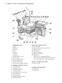
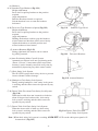
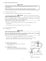
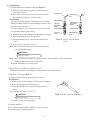
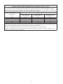
DENTAL UNIT AND CHAIR
OPERATING
INSTRUCTIONS
IMPORTANT
This manual provides operating instructions for SP-CLEO
The instructions contained in this booklet should be thoroughly read and
understood before operating the unit and chair.
File this manual and refer back to it for future maintenance.
0197
TABLE OF CONTENTS
1. OVERALL VIEW AND MAJOR COMPORNENTS........................... 1
2. DIMENSIONS AND SPECIFICATIONS
2-1. Chair Section.................................................................................. 2
2-2. Cuspidor Unit Section.................................................................... 2
2-3. Doctor Unit Section....................................................................... 3
3. OPERATING AND ADJUSTMENT INSTRUCTIONS
3-1. Master Switch Section................................................................... 4
3-2. Cuspidor Unit Section.................................................................... 4
3-3. Doctor Unit Section....................................................................... 6
3-4. Utility Section................................................................................ 9
3-5. Foot Control Section...................................................................... 9
3-6. Chair Section.................................................................................. 9
4. DAILY MAINTENANCE...................................................................... 13
5. ELECTROMAGNETIC COMPATIBILITY.......................................... 16
6. LIST OF COMPATIBLE HANDPIECES ............................................. 19
Intended Use of the Product
This product is an active therapeutic device intended for the exclusive use for diagnoses,
treatments and relative procedures of dentistry.
The product must be operated or handled by the qualified dentists or by dental staffs under
the supervision of the dentist.
Such dentists or dental staffs should instruct and/or assist the patients to approach to and
leave from the product.
Patients should not be allowed to operate or handle the product unless he/she is so instructed.
The product is supplied together with the handpieces like electric micromotor, air turbine
and/or motor, scaler and so on.
Environmental Requirements
Ambient Temperature
Operating +5 ℃- +40
Humidity
10 % - 80%
Atmospherical Pressure
600 hPa - 1060 hPa
℃
℃- +50
Storage -10 ℃
Compatibility of Handpieces
Use the compatible handpieces as shown on the attached list for this unit. (List of compatible
handpieces).
Important Notes
In case of the troubles, please contat Takara Belmont offices or your dealers.
Do not disassemble or attempt to repair.
Disassembly, repair or modifications shoud only be done by a qualified repair technician.
Attempts at disassembly, repair or modifications may lead to abnormal operation and accidents.
In case of disposal of equipment
When disposing the chair, appropriately dispose complying with all current applicable regulations and
local codes.
In EU area, EU directive 2002/96/EC on waste electrical and electronic equipment (WEEE) is applied
on this product. In this directive, environment conscious recycling/abandonment is obligated.
SYMBOLS
Chair last position
Chair auto return
Chair preset1
Chair preset2
Chair auto control
To raise the chair
To Recline
the backrest
To lower the chair
To raise
the backrest
Chair
manual control
Chair
manual control
Film viewer on/off
Fiber optic
handpiece light
on//off
Scaler
power control
Micro motor
rotation speed
control
Micro motor
Forward/Reverse
select
Handpiece coolant
spray on/off
Syringe
Store
Bowl flush
Cupfiller
Service outlet
water flow control
Service outlet
(water)
Service outlet (air)
Air
Type B
Applied Parts
Manufacturer
Date of manufacture
Water heater
Non-ionizing
radiation
Caution
It means “caution,
warnings, or
possibility to
danger”.
㹌
㻨㻦
㻵㻨㻳
Water
Authorized
representative in
the European
community
Separate
collection for
electrical and
electronic
equipment
㸶
1. OVERALL VIEW AND MAJOR COMPORNENTS
CHAIR SECTION
1. Chair
2. Headrest
3. Backrest
4. Seat
5. Legrest
6. Footrest
7. Armrests
8. Backrest Rear Cover
9. Base Cover
10. Power Supply Panel
11. Doctor Table Arm
12. Chair Preset Panel
13. Stick Switch (Manual Mode) CUSPIDOR UNIT SECTION
14. Cuspidor Unit
15. Cupfiller Nozzle
16. Bowl Flush Nozzle
17. Cuspidor Bowl
18. Assistant Side Control Panel
19. Saliva Ejector
20. 3-way Syringe
21. High Volume Evacuator
22. Assistant Holder
-1-
DOCTOR UNIT SECTION
23. Doctor Table
24. Doctor Table Main Control Panel
25. Dental Viewer
26. Doctor Tray
27. Waste Receptacle
28. Handpiece Holder
29. Handpieces
(Micromotor, Air Turbine/Motor,
Scaler and etc.) Manufacturers recommend
to use the handpieces with CE markings
FOOT CONTROL SECTION
30. Foot Control
LIGHT POST SECTION
31. Light Post
32. Light Pole
2. DIMENSIONS AND SPECIFICATIONS
2-1. CHAIR SECTION
605
570
13
487
5
10
10
82
215
70
495
530
480
460
185
487 ~ 787
452
1137 ~ 1437
1690
680
Seat Initial Height ..........................................................487 mm
Seat Elevation Stroke..........................................................300 mm
Headrest Slide Stroke..........................................................170 mm
Legrest Slide Stroke ..........................................................230 mm
Power Consumption ..........................................................230V, 50Hz 3.7A
Weight..................................................................................148 kg
Maximum Load....................................................................135 kg
Service Life..........................................................................10 years
2-2. CUSPIDOR UNIT SECTION
-2-
After Ser. No.DCQ080177
2-3. DOCTOR UNIT SECTION
BASE MOUNT TYPE
CART TYPE
-3-
3. OPERATING AND ADJUSTMENT INSTRUCTIONS
3-1. Master Switch Section
Fig.3-1 Master Switch and Power Indicator
(1) Master Switch (Fig.3-1)
Master switch is located at right side rear under
the doctor table.
Master switch turns the air, water and electric
power ON/OFF at the utility section.
When master switch is off, air and water are shut
off at hard pipings in the utility section.
It is always recommended to turn off master switch
when closing the office.
(2) Power Indicator (Fig.3-1)
Power indicator is located at centre of doctor table
main control panel.
When the master switch is ON position, a green
L.E.D. illuminates.
Note ; Before operation, turn on the main switch
for chair.
Ref. 3-6 (1-A) Main Switch for Chair.
3-2. Cuspidor Unit Section
(1) Cuspidor Section Control Panel (Fig.3-2)
Cuspidor section control panel is located inside of cuspidor unit body.
(1-A) Water Heater Switch (Fig.3-2)
Water heater switch allows warm water for
cupfiller.
Fig.3-2 Cuspidor Section Control Panel
(1-B) Cupfiller Flow Control Valve (Fig.3-2)
Cupfiller flow control valve adjusts cupfiller to suitable flow volume.
(1-C) Bowl Flush Flow Control Valve (Fig.3-2)
Bowl flush flow control valve adjusts bowl flush flow to optimum rinse action.
(l-D) Assistant side syringe flow control valves (Fig.3-2)
Assistant's syringe flow control valves adjust air and water to the assistant's syringe.
Yellow capped knob is air flow control valve, blue capped knob is water flow control valve.
Note ;Turning flow control knob to counter-clockwise, increases flow volume and turning to
clockwise, decreases .
-4-
(2) Assistant Side Control Panel (Fig.3-3)
Assistant side control panel is located on the
front side of cuspidor unit.
(2-E) Cupfiller Switch
Momentarily press the cupfiller switch and cup
will be filled with water. At the same time bowl
flush water will flush out about 12 seconds and
stop automatically.
Water filling time is set for 5 seconds at factory.
Note ; Cupfiller water flow volume can be
adjusted by cupfiller flow control valve.
Ref. 3-2. Cuspidor Section (1-B).
(2-F) Bowl Flush Switch
Momentarily press the bowl flush switch and
bowl flush water will flush continuously until
the bowl flush switch is pressed again.
Note ; Bowl flush water flow volume can be
adjusted by bowl flush flow control valve.
Ref. 3-2. Cuspidor Unit Section (1-C).
Fig.3-3 Assistant Side Control Panel
(2-G) Water Outlet
Water outlet provides quick-connect water.
(2-H) Control Knob for Water Outlet
Water flow adjustment provides water flow towater outlet.
(2- I) Assistant side Chair Auto-Positioning Switches
Ref. 3-6. Chair Section.
(3) Assistant Side Instrument Holder
Pick up the instrument (Saliva Ejector or High Volume Evacuator) from assistant holder it starts
working automatically.
Return the H.V.E. or S.E. handpiece to assistant holder, it stops after about 8 seconds working.
(Central vacuum type only)
(4) 3-way Syringe
By depressing either or both buttons, syringe offers air, water and spray.
Syringe tip can be rotated freely.
Syringe air, water and spray can be adjusted by syringe flow control valve.
Ref. 3-2. Cuspidor Section (1-D).
(5) Cupfiller Water Temperature Adjustment (Fig.3-4)
Cupfiller water temperature can be adjusted by water
heater temperature adjustment screw.
Water heater is located in cuspidor body and its
adjustment screw is located on top.
Turn to clockwise, increase cupfiller water
temperature and turn to counter-clockwise,
decrease water temperature.
Note ; Confirm water temperature at any time
after adjustment water heater.
-5-
Fig.3-4 Cupfiller Water Heater
Temperature Adjustment
3-3. Doctor Unit Section
(1) Doctor Table Main Control Panel (Fig.3-5)
Fig.3-5 Doctor Table Main Control Panel
(l-A) Dental Viewer
Intraoral film can be mounted by a magnetic bar.
(1-B) Dental Viewer Switch
Momentarily pressing turns ON/Off the viewer.
(1-C) Light Pack Switch (Option)
Momentarily press light pack switch, fiber optic light power will be turned on untill light pack
switch is pressed again.
(1-D) Bowl Flush Switch
Ref. 3-2. Cuspidor Unit Section (2-E).
(1-E) Cupfiller Switch
Ref. 3-2. Cuspidor Unit Section (2-F).
(1-F) Doctor Side Chair Auto-positioning Switches
Ref. 3-6. Chair Section.
(1-G) Doctor Side Chair Manual Control Switches
Ref. 3-6. Chair Section.
(2) Control Knobs (Fig.3-6)
Handpiece coolant water and air adjustment
knobs, syringe flow adjustment knobs are
located right hand side under the doctor table.
Fig.3-6 Doctor Unit Control Knobs
(2-H) Handpiece Coolant Water Adjustment Knobs
For individual handpiece coolant water adjustment, handpiece coolant water adjustment knobs
are lined up from front side HPl, HP2, HP3, ..
The handpiece holder numbers are from facing left hand side HPl, HP2, HP3, ..
(2- I) Handpiece Coolant Air Adjustment Knob
Handpiece coolant air adjustment knob controls the flow of coolant air to all handpieces.
(2-J) Doctor Side Syringe Flow Adjustment Knobs
Doctor side syringe flow adjustment knobs adjust air and water to doctor side syringe.
Yellow capped knob is air control knob, blue capped knob is water control knob.
(2-K) Master Switch
Ref. 3-1. Master Switch Section.
Note ; Turning flow control knob to counter-clockwise, increases flow volume and turning to
clockwise, decreases.
-6-
(3) Handpiece Drive Air and Coolant Air Adjustment Screws (Fig.3-7, Fig.3-8)
Loosen 4-screws from the table bottom and open the table top. Auto select valve and handpiece
pressure gauge are located in the table.
Caution ; Please remove the table top carefully, because the table top is connected with wires
behind the table top.
(3-L) Handpiece Drive Air Adjustment Screw (Fig.3-8)
Adjustment of drive air to each handpiece can be made by the screw on the auto select valve.
It is important to set the drive air pressure in accordance to the handpiece manufacture's
recommendation.
Setting The Optimum Condition
Turn the appropriate dive air screw fully clockwise, depress drive air pedal of foot control to fully
open (maximum foot pressure) and turn the adjustment screw slowly in counter-clockwise
direction. Stop turning the screw immediately when handpiece pressure gauge shows the desired
drive air pressure.
(3-M) Handpiece Coolant Air Adjustment Screws (Fig.3-8)
Handpiece coolant air adjustment screws are provided for individual adjustment of handpiece
coolant air.
Fig.3-8 Auto Select Valve
Fig.3-7 Doctor Table Inside
(4) Control Knobs and Switches for Optional Euipment (Fig.3-9)
SP-CLEO can be available fiber optic, electric scaler
and electric motor as factory option.
They can be controlled by the doctor unit section and
foot control.
(4-A) Electric Motor Power Control Knob (Option)
Electric motor rotation speed can be controlled by
electric motor power control knob.
Turning electric motor power control knob to clockwise,
increases rotation speed and turning tocounter-clockwise,
decreases rotation speed.
Fig.3-9 Control Knobs and Switchs
for Optinal Equipment
(4-B) Scaler Power Control Knob (Option)
Scaler power can be controlled by scaler power control kob. Turning scaler power control knob to
clockwise, increases scaler power and turning to counter-clockwise decreases scaler power.
(4-C) Electric Motor Forward/Reverse Rotation Switch (Option)
To turn electric motor forward/reverse rotation switch to facing right side, electric motor
rotates forward and to turn to facing left side, electric motor rotates reverse.
CAUTION
Handpiece : Refer to handpiece manufacturers operating instructions.
-7-
(5) Handpiece Holder Angle (Fig.3-10)
Handpiece holder angle can be adjusted by loosing
M4 set screw at facing left hand side under the handpiece holder arm.
After adjustment retighten M4 set screw.
Handpiece holder angle can not be adjusted individually.
Fig.3-10 Handpiece Holder Angle
Adjustment Set Screw
(6) Lock Knob for Doctor Table Height Adjustment (Fig.3-11)
While supporting the doctor table by a hand, loosen lock knob to counter-clockwise and doctor
table will go up and down freely.
Adjust the height of doctor table and then tighten lock knob firmly.
Base Mount Type
Cart Type
Fig.3-11 Lock Knob
(7) Level Adjustment Screws for Doctor Table (Fig.3-12)
Level of the doctor table can be adjusted by
screwing/unscrewing four set screws located
in the doctor table.
Remove the table top and adjust the level by
screwing/unscrewing the four set screws (level
adjustment screws).
Retighten the four set screws firmly.
Fig.3-12 Level Adjustment Screws
(8) Friction Adjustment set screw of table rotation (Fig.3-13)
Friction of table rotation can be adjusted by the set
screw located in table rotation flange under the table.
(9) Friction Adjustment Nut of Horizontal Arm (Fig.3-14)
Friction of horizontal arm can be adjusted by
turning the nut located at the end of the horizontal arm.
Fig.3-13 Table Rotation Friction
Adjustment Set Screw
Fig.3-14 Friction adjustment of Horizontal Arm
-8-
3-4. Utility Section (Fig.3-15)
(1) Air Pressure
Regulate the output air pressure of compressor to the
utility section at 0.54 - 0.59 Mpa (5.5 - 6.0 kg/cm2 )and air
flow volume is at least 55 Nl/min (88 Nl/min ; in case of
air vacuum type)
Adjust the air regulator in the utility section at
0.49 - 0.54 Mpa (5.0 - 5.5 kg/cm2 ) [already adjusted at
factory, Max. 0.49 Mpa (5.0 kg/cm2 .)]
(2) Water Pressure
More than 0.1 Mpa (1.0 kg/cm2 ) water pressure at the
regulator in the utility section is requested for
operating this unit efficiently.
Adjust the water regulator in the utility section
at 0.1 - 0.19 Mpa (1.0 - 2.0 kg/ cm2 ). [Already adjusted at
factory, Max. 0.19 Mpa (2.0 kg/cm2 .)]
Note ; In case of water saliva ejector, high water
pressure supplies efficient suction power.
Fig.3-15 Utility Section
3-5. Foot Control Section (Fig.3-16)
(1) Drive Air Pedal
Handpiece speed can be controlled by drive air pedal.
(2) Coolant Water ON/OFF Switch
Coolant water ON/OFF switch allows for coolant water
to be turned on or off without disturbing flow
adjustment.
(3) Chip Blower Button
By treading chip blower button on, chip blower
comes out from handpiece without bur turning.
On
Off
CHIP BLOWER BUTTON
COOLANT WATER On/Off SWITCH
3-6. Chair Section
(1) Chair Power Supply Panel (Fig.3-17)
Chair power supply panel is located on sitting right
hand side chair base.
DRIVE AIR PEDAL
Fig.3-16 Foot Control
(1-A) Main Switch for Chair
Main switch for chair turns electric power ON/OFF.
Neon lamp in the main switch illuminates in green
when chair and unit electric power is ON.
(1-B) Fuse Holder and Fuse
An over current protection device rated for
6.3A (230 type).
Fig.3-17 Chair Power Supply Panel
-9-
Fig.3-18 Doctor Table Main Control Panel
(2) Chair Manual Control Switches (Fig.3-18, Fig.3-19)
Chair manual control switches are located on the doctor
table main control panel and the sitting right hand side
base cover (Stick Switch).
(2-A) Seat Height Adjustment
To Raise ; press ( ) button on main control panel or move
up stick switch.
To Lower ; press ( ) button on main control panel or move down stick switch.
(2-B) Backrest Angle Adjustment
To Raise ; press ( ) button on main control panel
or move right stick switch.
To Recline; press ( ) button on main control panel
or move left stick switch.
Fig.3-19 Stick Swich
(3) Chair Auto Positioning Switches (Fig.3-18, Fig.3-20)
Chair auto positioning switches are located on the
doctor table main control panel and the assistant
side control panel.
(3-A) Preset Operation
This chair has two preset positions. (Preset 1 and Preset 2).
Momentarily press (1) button on main control panel or
assistant side control panel, chair will move to preset 1
position automatically.
(Preset 2 is operated by (2) button.)
(3-B) Auto-return Operation
Momentarily press (0) button on main control panel
or assistant side control panel, chair will return to the
initial position (Seat is fully lowered and backrest
is upright position with footrest retracted).
Note ; Footrest section operation can be controlled by only
auto positioning mode.
Fig.3-20 Assistant side Control Panel
(3-C) Last Position Memory Operation
Momentarily press (LP) button at reclined backrest position (treatment position) and backrest will
raise to mouth rinsing position.
Press momentarily LP button again, backrest will recline to previous treatment position.
Note ; Seat height can not be changed by (LP) button.
-10-
(4) Headrest
(4-A) Standard Type Headrest (Fig.3-21)
Height Adjustment
Press down or pull up headrest to the position
required.
Angle Adjustment
Push the headrest forward as required.
Lift the headrest lever to rotate the headrest
backward.
(4-B) Twin Axis Type Headrest (Option)(Fig.3-22)
Height Adjustment
Press down or pull up headrest to the position
required.
Angle Adjustment
Holding the headrest cushion, grip the headrest
release button and headrest can be moved freely.
Adjust the headrest to suitable position and
release headrest release button.
(5) Armrest Rotation (Fig.3-23)
Sitting right hand side armrest can be rotated
by pulling outward.
Fig.3-21
Standard Type Head-
Fig.3-22 Twin Axis Headrest
(6) Auto Positioning Mode Cancell System
Automatic movement in all auto positioning mode
(Preset 1, Preset 2, Auto-return and Last position
memory) can be instantly cancelled at any time by
momentarily depressing any chair control switch.
(7) Chair Safety Lock System
The SP-CLEO equips chair safety device to prevent
from accidental crash or damage.
(7-A) Handpiece Chair Safety Lock System
During runinig handpiece, chair safety lock system
is working and the chair can not be operated by any
switch.
Fig.3-23 Armrest Rotation
(7-B) Doctor Table First Arm Chair Safety Lock System
(Fig.3-24)
When doctor table first arm is turned to clockwise
about 30 degree into backrest side, chair safety
lock system is working and the chair can not be
operated by any switch.
(7-C) Doctor Table Lift Chair Safety Lock System
When the doctor table is lifted up, chair safety
lock system is working and the chair can not be
operated by any switch.
Fig.3-24 Doctor Table First Arm
Chair Safety Lock System
Note ; When chair safety lock system is working, LOCK OFF L.E.D. on the chair preset panel will
be turned off. (Fig.3-25)
-11-
(8) Preset Position Adjustment (Fig.3-25)
Fig.3-25 Chair Preset Panel
1. Set seat and backrest in the desired position by manual control switches.
2. Keep depressing (1) button on doctor table or assistant side control panel until buzzer sounds
so that the position is memorized to PRESET 1, then the buzzer sound ceases.
3. PRESET 2 is memorized by pressing (2) button as following 1 to 2.
(9) Mouth Rinsing Backrest Position Adjustment (Fig.3-25)
The desired mouth rinsing backrest position can be programmed as last position memory operation.
1. Set backrest in the desired position by manual control switches.
2. Keep depressing (LP) button on doctor table or assistant side control panel until buzzer sounds
so that the position is memorized to mouth rinsing position, then the buzzer sound ceases.
-12-
4.CARE AND MAINTENANCE
CAUTION
Turn off the master switch at the initial position after daily operation or in long
term interval.
Turn off the main water valve after daily operation or in long term interval.
4-1. Care and maintenance for chair
4-1-1. Other than cleaning, no scheduled maintenance of chair is required.
CAUTION
Do not drench the chair for cleaning.
Do not use polishing powder, solvents, strong disinfectant and hot water for cleaning.
After cleaning, wipe with a dry soft cloth and keep dry.
Upholstery can be cleaned with a neutral detergent.
Paint parts, metal parts and plastic parts can be cleaned with DURR FD333 cleaner
( or equivalent).
Do not drench the chair and unit. Wipe all surfaces dry after cleaning.
4-2. Care and maintenance for unit
4-2-1. Cleaning unit
CAUTION
Do not drench the unit for cleaning.
Do not use polishing powder, solvents, strong disinfectant and hot water for cleaning
After cleaning, wipe with a dry soft cloth and keep dry.
All surfaces can be cleaned with DURR FD333 cleaner ( or equivalent).
Spray the cleaner (DURR FD333) on cloth and wipe the surfaces with the cloth.
Do not drench the chair and unit. Wipe all surfaces dry after cleaning.
4-1. Basket Strainer (Fig.4-1)
Take out the basket strainer in centre of cuspidor
bowl and clean it.
4-2. Solid Collector (Fig.4-1)
Open the side panel of the cuspidor body and take
out solid collector container and filter and clean them.
Fig.4-1 Cuspidor Bowl
-13-
4-3. Handpieces
1. Vacuum Handpiece and Saliva Ejector (Fig.4-2)
A. Pull and remove the top parts of each handpiece
and clean strainer.
B. After daily operation, run two cup of clean water
through the handpieces to clean inside.
Sterilization
Vacuum Tip/Saliva Ejector Tip/Vacuum Cap/Vacuum
Handpiece Body/Saliva Ejector Handpiece Body can be
sterilized with autoclave.
Vacuum handpiece body and saliva ejector body must
be assembled before autoclaving.
A. Wash off dirt of the handpiece with natural detergent.
B. Rinse the handpiecwe with tap water.
C. Insert the handpiece in a sterilization pouch and
seal it.
D. Autoclave for 20 min. at 121℃.
Vacuum Tip
Saliva Ejector
Tip
Vacuum Cap
Vacuum
Handpiece
Body
Slide Knob
Vacuum
Hose
Saliva Ejector
Handpiece
Body
Slide Knob
Saliva Ejector
Hose
Fig.4-2 H.V.E. and S.E. Hand
-piece
Note: The slide knob can be autoclaved 100 times and
is an expendable supply.
CAUTION
• Skip dry cycle.
Note : After cleaning the handpieces, apply a white vaseline lightly on the rubber parts
(O-Ring) and screws parts for long life.
Keep the handpieces in a clean place.
2. Micro Motor / Air Motor / Turbine / Scaler
Sterilize the handpiece according to manufacturer’s operating manual.
3. Belmont 77 Syringe (Fig.4-3 )
A. Remove the nozzle from syringe and clean it
Sterilization
A. Wash off dirt of the handpiece with natural detergent.
B. Rinse the handpiecwe with tap water.
C. Insert the handpiece in a sterilization pouch and
seal it.
D. Autoclave for 20 min. at 121℃.
CAUTION
• Skip dry cycle.
Keep the syringe in a clean place.
4. Tubing and Hose
It is recommended that Durr FD333 be used to clean
the exterior parts of tubing and hose
-14-
Fig.4-3 H.V.E. and S.E. Handpiece
4-4. Drain Valve for Air Filter in Utility Section (Fig.4-4)
Open the drain valve once a week to drain off the
water from the air filter in utility section.
4-5. Vinyl leather of chair
Wipe the vinyl leather with soft cloth using upholstery
cleaner.
4-6. Master Switch
After the daily operation and maintenance, turn off the
master switch under the doctor table.
Ref. 3-1. Master Switch Section
-15-
Fig.4-4 Utility Section
5.ELECTROMAGNETIC COMPATIBILITY(EMC)
Medical electrical equipment needs special precautions regarding EMC and needs to be installed and put into
service according to the EMC information provided in this manual.
Portable and mobile RF communications equipment can affect medical electrical equipment.
The equipment or system should not be used adjacent to or stacked with other equipment. If adjacent or stacked
use is necessary, the equipment or system should be observed to verify normal operation in the configuration in
which it will be used.
Guidance and manufacture’s declaration - electromagnetic emissions
The SP-CLEO is intended for use in the electromagnetic environment specified below. The customer or the user of the
SP-CLEO should assure that it is used in such an environment.
Emissions test
Compliance
Electromagnetic environment - guidance
RF emissions
The SP-CLEO uses RF energy only for its internal function.
CISPR 11
Therefore, its RF emissions are very low and are not likely
Group 1
to cause any interference in nearby electronic equipment.
RF emissions
The SP-CLEO is suitable for use in all establishments,
Class B
CISPR 11
including domestic establishments and those directly
Harmonic emissions
connected to the public low-voltage power supply network
Class A
IEC 61000-3-2
that supplies buildings used for domestic purposes.
Voltage fluctuations/
Flicker emissions
Complies
IEC 61000-3-3
Guidance and manufacture’s declaration – electromagnetic immunity
The SP-CLEO is intended for use in the electromagnetic environment specified below. The customer or the user of the
SP-CLEO should assure that it is used in such an environment.
IEC 60601
Electromagnetic environment Immunity test
Compliance level
test level
guidance
Electrostatic
±6 kV contact
±6 kV contact
Floors should be wood, concrete or
discharge (ESD)
±8 kV air
±8 kV air
ceramic file. If floors are covered
IEC 61000-4-2
with synthetic material, the relative
humidity should be at least 30%.
Electrical fast
±2 kV for power
±2 kV for power
Mains power quality should be that
transient/burst
supply lines
supply lines
of a typical commercial or hospital
IEC 61000-4-4
±1 kV for input/output
±1 kV for input/output
environment.
lines
lines
Surge
±1 kV differential mode
±1 kV differential mode
Mains power quality should be that
IEC 61000-4-5
±2 kV common mode
±2 kV common mode
of a typical commercial or hospital
environment.
Voltage dips, short
<5% UT
<5% UT
Mains power quality should be that
interruptions and
(>95% dip in UT)
(>95% dip in UT)
of a typical commercial or hospital
voltage variations
for 0.5 cycle
for 0.5 cycle
environment. If the user of the SPon power supply
40% UT
40% UT
CLEO requires continued operation
input lines
(60% dip in UT)
(60% dip in UT)
during power mains interruptions, it
IEC 61000-4-11
for 5 cycle
for 5 cycle
is recommended that the SP-CLEO
70% UT
70% UT
be powered from an uninterruptible
(30% dip in UT)
(30% dip in UT)
power supply or a battery.
for 25cycle
for 25cycle
<5% UT
<5% UT
(>95% dip in UT)
(>95% dip in UT)
for 5 s
for 5 s
Power frequency
3 A/m
3 A/m
Power frequency magnetic fields
(50/60 Hz)
should be at levels characteristic
magnetic field
of a typical location in a typical
IEC 61000-4-8
commercial or hospital environment.
NOTE UT is the a.c. mains voltage prior to applications of the test level.
-16-
Guidance and manufacture’s declaration - electromagnetic immunity
The SP-CLEO is intended for use in the electromagnetic environment specified below. The customer or the user of the
SP-CLEO should assure that it is used in such an environment.
Compliance
Immunity test
IEC 60601 test level
Electromagnetic environment - guidance
level
Portable and mobile RF communications equipment should be used no closer to any part of the SPCLEO, including cables, than the recommended
separation distance calculated from the equation
applications to the Frequency of the transmitter.
Conducted RF
IEC 61000-4-6
3 Vrms
150 kHz to 80 MHz
outside ISM bandsa
3 Vrms
Radiated RF
IEC 61000-4-3
3V/m
80 MHz to 2.5 GHz
3 V/m
Recommended separation distance
d = 1.2√P
d = 1.2√P 80 MHz to 800 MHz
d = 2.3√P 800 MHz to 2.5 GHz
Where P is the maximum output power rating of the
transmitter in watts (W) according to the transmitter
manufacturer and d is the recommended separation
distance in metres (m).
Field strengths from fixed RF transmitters, as
determined by an electromagnetic site survey,a should
be less than the compliance level in each frequency
range.b
Interference may occur in the vicinity of equipment
marked with the following symbol:
NOTE 1 At 80 MHz and 800MHz, the higher frequency range applies.
NOTE 2 These guidelines may not apply in all situations. Electromagnetic propagation is affected by adsorption and
reflection from structures, objects and people.
a Field strengths from fixed transmitters, such as base stations for radio (cellular/cordless) telephones and land mobile
radios, amateur radio, AM and FM radio broadcast and TV broadcast cannot be predicted theoretically with accuracy.
To assess the electromagnetic environment due to fixed RF transmitters, an electromagnetic site survey should be
considered. If the measured field strength in the location in which the SP-CLEO is used exceeds the applicable RF
compliance level above, the SP-CLEO should be observed to verify normal operation. If abnormal performance is
observed, additional measures may be necessary, such as reorienting or relocating the SP-CLEO.
b Over the frequency range 150 kHz to 80 MHz, field strengths should be less than 3V/m.
Essential performance (purpose of IMMUNITY testing)
Unless operated by the switches for chair control, the chair section of the SP-CLEO does not make any movements,
except for sounding a buzzer and switching on/off the indicator.
-17-
Recommended separation distances between
Portable and mobile RF communications equipment and the SP-CLEO
The SP-CLEO is intended for use in an electromagnetic environment in which radiated RF disturbances are controlled.
The customer or the user of the SP-CLEO can help prevent electromagnetic interference by maintaining a minimum
distance between portable and mobile RF communications equipment (transmitters) and the SP-CLEO as recommended
below, according to the maximum output power of the communications equipment.
Separation distance according to frequency of transmitter
Rated maximum output power
m
of transmitter
150 kHz to 80 MHz
80 MHz to 800 MHz
800 MHz to 2.5 GHz
W
d = 1.2√P
d = 1.2√P
d = 2.3√P
0.01
0.12
0.12
0.23
0.1
0.38
0.38
0.73
1
1.2
1.2
2.3
10
3.8
3.8
7.3
100
12
12
23
For transmitters rated at a maximum output power not listed above, the recommended separation distance d in metres
(m) can be estimated using the equation applicable to the frequency of the transmitter, where P is the maximum output
power rating of the transmitter in watts (W) according to the transmitter manufacturer.
NOTE 1 At 80 MHz and 800MHz, the separation distance for the higher frequency range applies.
NOTE 2 These guidelines may not apply in all situations. Electromagnetic propagation is affected by adsorption and
reflection from structures, objects and people.
-18-
6. LIST OF COMPATIBLE HANDPIECES
DESCRIPTION
Syringe
DCI (3-WAY)
Turbine
BIEN AIR BORA S36L / UNIFIX with LIGHT
NSK Ti-Max X
Air motor
BIEN AIR Aquilon 830 / UNIFIX with LIGHT /PM1132
NSK EX-203 / EX-6
Micromotor
BIEN AIR MC3LK / PLMP021PCB. / PM1132
BIEN AIR MC3LK / PL970 PCB. / PM1132
Scaler
SATELEC SP4055 w/Light
-19-
NOTE
Takara Belmont (UK) Ltd.
Belmont House
One St.Andrews Way,Bow,
London E3 3PA U.K.
Tel: (44)20 7515 0333
Fax:(44)20 7987 3596
TAKARA BELMONT CORPORATION
2-1-1, Higashishinsaibashi,Chuo-ku,Osaka,542-0083,Japan
TEL : 81-6-6213-5945
FAX : 81-6-6212-3680
BOOK NO. AFFY23E0
Printed in Japan 1110