1
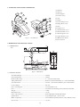
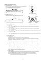
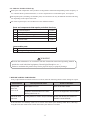
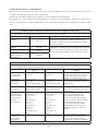
DENTAL CHAIR
OPERATING
INSTRUCTIONS
IMPORTANT
This manual provides operating instructions for the CLESTA II.
The instructions contained in this booklet should be thoroughly read and
understood before operating the chair.
After the installation is completed, keep this manual in a safe place and referto it for
future maintenance.
TABLE OF CONTENTS
Page
SAFETY PRECAUTIONS----------------------------------------------------------- 1
1. OVERVIEW AND MAJOR COMPONENTS--------------------------------- 4
2. DIMENSIONS AND SPECIFICATIONS--------------------------------------- 4
4. AUTO MODE POSITION ADJUSTMENT------------------------------------ 6
3. OPERATING INSTRUCTIONS
3-1. MAIN SWITCH--------------------------------------------------------------- 5
3-2. CONTROLS------------------------------------------------------------------- 5
3-3. SAFETY LOCK DEVICE--------------------------------------------------- 6
3-4. HEADREST OPERATIONS------------------------------------------------ 6
5. CARE AND MAINTENANCE--------------------------------------------------- 7
6. MAINTANANCE AND INSPECTION
6-1. GUIDE FOR DAILY MAINTENANCE AND INSPECTION--------- 8
(Maintenance and inspection by user)
6-2. GUIDE FOR PERIODICAL CHECK-UP--------------------------------- 9
7. BEFORE ASKING FOR REPAIRS---------------------------------------------- 9
8. ELECTROMAGNETIC COMPATIBILITY(EMC)---------------------------10
SYMBOLS
Following symbols are used in this manual of CLESTA II CHAIR. Confirm the meaning of
each symbol.
Chair last position
Chair auto return
Chair preset1
Chair preset2
To raise the chair
To Recline
the backrest
To lower the chair
To raise
the backrest
Alternating current
Protective earth
(ground)
Functional earth
(ground)
Chair manual
control
Date of manufacture
Refer to instruction
manual/booklet
Non-ionizing
radiation
Caution
It means “caution,
warnings, or
possibility to danger”.
㻨㻦
㻵㻨㻳
Authorized
representative in the
European community
Separate collection
for electrical and
electronic equipment
SN
Serial number
Manufacturer
Type B
Applied Parts
Intended Use of the Product
This product is intended for the exclusive use for diagnoses, treatments and relative procedures
of dentistry, and must be operated or handled by the qualified dentists or by dental staffs under
the supervision of the dentist.
Such dentists or dental staffs should instruct and/or assist the patients to approach to and leave
from the product.
Patients should not be allowed to operate or handle the product unless he/she is so instructed.
Environmental Requirements
℃
℃- +50
Ambient Temperature Operating +5 ℃- +40 Storage -10 ℃
Humidity 10 % - 80%
Atmospherical Pressure 600 hPa - 1060 hPa
Important Notes
In case of the troubles, please contat Takara Belmont offices or your dealers.
Do not disassemble or attempt to repair.
Disassembly, repair or modifications shoud only be done by a qualified repair technician.
Attempts at disassembly, repair or modifications may lead to abnormal operation and accidents.
In case of disposal of equipment
When disposing the chair, appropriately dispose complying with all current applicable regulations and
local codes. In EU area, EU directive 2002/96/EC on waste electrical and electronic equipment (WEEE) is applied on this product. In this directive, environment conscious recycling/abandonment is obligated.
SAFETY PRECAUTIONS
■ Before use, read the “Safety precautions” carefully to ensure proper use.
■ The following information is designed to ensure safe use of this product and to prevent injury and damage
to you and others. The precautions contained here are classified depending on the severity and degree of
imminence of possible injury or damage resulting from improper use. Be sure to follow all the
information, which is important for safety.
Severity and degree of imminence of possible injury or damage
Classification of precautions
WARNING
This symbol indicates that “ignorance of these precautions may lead to severe
injury or even death as a result of improper use.”
CAUTION
This symbol indicates that “ignorance of these precautions may lead to mild
or moderate physical injury or damage to property as a result of improper use.”
NOTICE
This symbol indicates that “it is recommended to follow these precautions
for safety.”
WARNING
1. Be sure to turn off breakers for equipment in the clinic when this product will not be used for a long
period of time
Be sure to turn off breakers for equipment in the clinic when this product will not be used for a long period of
time (following the completion of work, during the suspension of business, etc.). Insulation degradation may
cause electrical fire.
2. Be sure to turn off the main switch upon completion of work or during work breaks
Be sure to turn off the main switch upon completion of work or during work breaks. This prevents incorrect
operation due to accidental contact and associated hazards.
3. Do not sit on other than seat
When the backrest is at the forward position. do not sit on or place an undue load on the headrest or legreat of
dental chair. This could cause the unit to topple or could damage the unit.
4. Do not place an undue load on the arm
Do not get on or place an undue load on the dental chair armrest. This could cause the unit to topple or other
accidents.
5. Connect to an appropriate power source
This equipment must be connected to an appropriate power source.
6. Be sure to establish a grounding connection
Be sure to establish a proper grounding connection. (Refer to a vendor for grounding connection.) Failure or
electric leakage may lead to electric shock.
7. Never disassemble, repair or modify this product
Individuals other than certified repair technicians should not disassemble or attempt to repair and modify this
product. This could lead to an accident, failure, electric shock or fire.
8. Use with caution in the presence of electromagnetic interference waves
Do not place this product around equipment generating electromagnetic waves (including communications
equipment, elevators, etc.) as incorrect operation of this product may occur in the presence of electromagnetic
interference waves. Do not use equipment generating electromagnetic waves, such as mobile phones, around this
product.
-1-
SAFETY PRECAUTIONS
WARNING
9. Be sure to turn off the main switch when electrocautery is in use
Be sure to turn off the main switch when electrocautery is in use, because noise may cause incorrect operation of
this product.
10. Ensure the maintenance of this product
• Failure to maintain this product may lead to physical injury or property damage.
• Refer to the section of maintenance.
11. Immediately wipe off any water spills or leakage on the floor
Immediately wipe off any water spills or leakage on the floor. Decreased strength of the floor may lead
to physical injury including fall, or property damage.
12. Use with caution on patients with a cardiac pacemaker
Use this product with extreme caution on patients with a cardiac pacemaker. In the case of any abnormalities in
patients during use, immediately turn off this product and discontinue use.
CAUTION
1. Only experienced personnel should use this product
Only dentists or other dental professionals should use this product.
2. Confirm safety before use.
Before use, confirm that the parts are correctly and safely operating and that there are no obstacles around this
product.
3. Pay attention to patients and children
Keep your eyes on patients (especially, children) so that mischief or inadvertent operation of equipment will
not lead to unexpected accidents.
4. Discontinue use if you feel that “something is wrong”
Always be careful to inspect this product for looseness, rattling, tilting, wobbling, sounds, temperature, odors,
etc. Immediately discontinue use at the first feeling that “something is wrong.”
5. keep your eyes on the patient during operation.
• Confirm that the patient is seated in the proper position. Keep your eyes on the patient during the operation.
• Pay special attention to surroundings at automatic operation of the dental treatment table. Damage
to the
backrest, stool or Doctor's table may occur.
6. Do not smack or rub this product
Do not smack or rub this product forcefully. This could cause damage to covers or defective function.
7. Precautions for cleaning the resin cover
For cleaning, do not use cleaning agents containing solvent or abrasives, thinners or oil-based alcohol (butanol
and isopropyl alcohol), which may cause cracks.
-2-
SAFETY PRECAUTIONS
CAUTION
8. Be sure to operate switches with your hands
Be sure to operate switches with your hands, except the foot controller, which is operated with your foot.
Operation with body parts other than hands may cause damage or incorrect operation.
9. Pay attention during the headrest operation
Do not allow hands, fingers, or hair to become entangled in the moving parts of the headrest during operationg
10. Precautions for cleaning
• Never use sandpaper, metal scrub brushes and abrasive cleaning agents to clean the unit.
• Do not use strongly acidic cleaning agents or alkaline pipe cleaning agents to avoid corrosion of metals, etc.
11. Read the documents accompanying the various pieces of equipment
Before use, be sure to carefully read the package inserts and Instruction Manuals accompanying the various
pieces of equipment (including optional articles) to ensure proper use.
NOTICE
1. Troubleshooting and contact information
In the case of any problems, discontinue use, turn off the main switch and contact the dealer or our company.
2. Handling of equipment in the case of a power failure
Put the handpiece in the holder and turn off the main switch if equipment stops working during use due to a power
failure or other reasons.
-3-
1. OVERVIEW AND MAJOR COMPONENTS
(1) Headrest
(2) Backrest
1
(3) Back Support
2
(4) Armrest (Left)
4
11
12
3
5
6
13
7
14
7
16
8
15
9
16
(5) Seat
(6) Flange
(7) Lower Flange Cover
(8) Flange Hose Cover
(9) Base
(10) Pump Cover
(11) Headrest Rear Cover
(12) Backrest Rear Cover
(13) Back Support Cover
(14) Upper Flange Cover
10
(15) Main Switch Panel
Fig.1-1 Overall View
(16) Foot Control
2. DIMENSIONS AND SPECIFICATIONS
60
2-1. DIMENSIONS
-mm-
255
170
178
˚
410
80
˚ 8˚
11˚
5˚
1105
50
630
600
510
225
565
2-2. SPECIFICATIONS
1813
1188
60
610
Fig.2-1 Dimensions
Seat Initial Height------------------------------------------------------ 410mm
Seat Lifting Stroke------------------------------------------------------ 380mm
Backrest Movement---------------------------------------------------- 0˚ ~ 80˚ above Horizontal
Tilting Mechanism------------------------------------------------------ Backrest Synchronized Tilting (5˚ ~ 11˚ above Horizontal)
Auto Movements ------------------------------------------------------ 2-Preset, 1-Last Position Memory and 1-Auto Return
Control Voltage ------------------------------------------------------ DC.12V
Power Consumption---------------------------------------------------- AC230V, 50Hz 2.0A
Fuse ---------------------------------------------------------------------- 5A/250V(Current Rating:50A at 250VAC) Fast-blow
Weight-------------------------------------------------------------------- 115Kg
Maximum Load--------------------------------------------------------- 135 kg
Class of Foot Swirch--------------------------------------------------- IPX1 (applicable standars,IEC60529)
Applied Parts------------------------------------------------------------ Type B applied part : Seat for chair
Mode of Operation ----------------------------------------------------- Non-Continuous Operation/ON time:3 min, OFF time:15min
Service Life-------------------------------------------------------------- 10 years
-4-
3. OPERATING INSTRUCTIONS
3-1. MAIN SWITCH (Fig.1-1 & Fig.3-1)
Turn on the main switch located on the left side of the pump cover.
A green lamp in the main switch will illuminate.
FUSE
CAUTION
I
Operate the main switch by hand only.
Turn off the main switch after daily operation.
O
ON
Main Switch
OFF
MAINS
3-2. CONTROLS (Fig.3-2)
Before operating the chair, confirm that it is safe for the
patient and the operator.
CAUTION
Fig.3-1 Main Switch
Preset-1
Foot Switch Disc
2
1
All chair electrical movements can be controlled
by the foot switch.
Preset-2
0
Auto Return
LP
Last Position
Memory
Fig.3-2 Foot Control
(1) Manual Mode Control
A. Seat Lifting
Keep depressing ( ) side of the foot control disc until the seat is lifted up to the desiredposition.
B. Seat Lowering
Keep depressing ( ) side of the foot control disc until the seat is lowered to the desired position.
C. Backrest Reclining
Keep depressing ( ) side of the foot control disc until the backrest is reclined to the desired position.
D. Backrest Raising
Keep depressing ( ) side of the foot control disc until the backrest is rased up to the desired position.
(2) Auto Mode Control
E. Preset Control
CLESTA II chair has two preset positions. (Preset-1 and Preset-2)
Momentarily depress ( 1 ) button on the foot control, the chair will move to the preset-1 position
automatically. (Preset-2 is operated by ( 2 ) button.)
F. Auto Return
Momentarily depress ( 0 ) button on the foot control, the chair will return to the initial position.
(The seat is fully lowered and the backrest is in the upright position.),
G. Last Position Memory
Momentarily depress (LP) button at the reclined backrest position (treatment position), the backrest
will raise to the mouth rinsing position automatically.
Momentarily depress (LP) button again, the backrest will recline to the previous treatment
position automatically.
Note : Seat height can not be changed by (LP) button.
H. Emergency Stop
During automatic procedure (Preset, Auto return and Last position memory), depress of any side of
the disc or buttons on the foot control will cancel the automatic movement immediately.
Note : Do not depress auto mode button ( 1 )( 2 )( 0 )(LP) for over 3 seconds, because the
memorized position in auto mode may be changed.
-5-
3-3. SAFETY LOCK DEVICE (Fig.3-3)
All chair movements can be stopped automatically
by the safety lock device when pressure is detected
between the base and the sub link cover.
If the safety device has been activated, simply operate
the base up button and remove the object causing the
safety device to activate from this area.
Note : Seat lifting and backrest rasing can be
operated when the safety lock device is
activated.
3-4. HEADREST (Fig.3-4)
(1) Height Adjustment
Press down or pull up the headrest to the desired height.
(2) Angle Adjustment
Push the headrest forward as required.
Lift the headrest lever to rotate backward and release the lever
Sub Link Cover
Fig.3-3 Safety Lock Device
Angle
Adjustment
Headrest
Lever
Height
Adjustment
at the desired angle.
Fig.3-4 Headrest
3-5. DOUBLE ARTICULATING HEADREST (Optional) (Fig.3-5)
(1) Height Adjustment
Press down or pull up the headrest to the desired height.
(2) Angle Adjustment
Angle of headrest can be changed by grasping the headrest
release lever on headrest mechanism.
4. AUTO MODE POSITION ADJUSTMENT
(1) Preset position Adjustment (Fig.4-1)
Two preset positions can be set.
A.Set the seat and the backrest to the desired preset position
by manual control switch.
B.Keep depressing preset 1 switch (1) until buzzer sounds
(in about 3 seconds), then release it.
C. The position is memorized for Preset-1.
D. Preset-2 can be memorized by depressing preset 2 switch (2),
as following A to C.
Safety Lock
Device
Base
Headrest Release
Lever
Fig.3-5 Double Articulating Headrest
Manual Control Switch
Preset-2
Preset-1
2
1
0
Auto Return
LP
Last Position
Memory
Fig.4-1 Foot Control
(2) Mouth Rinsing Position Adjustment (Fig.4-1)
Mouth rinsing position in last position memory movement can be adjusted.
A. Set the backrest to the desired mouth rinsing position by manual control switch.
B. Keep depressing last position memory switch (LP) until buzzer sounds (in about 3 seconds)
and release it.
C. This backrest position is then memorized as the mouth rinsing position.
-6-
5. CARE AND MAINTENANCE
Chair Cleaning
The surface of the chair’s seating area is made of synthetic leather. Apply dry wiping or wipe the surface with
cloth moistened with either water or diluted neutral detergent for the care.
If the color of clothing or belt remained on the synthetic leather, wipe it off with cloth moistened with diluted
neutral detergent as soon as possible, to avoid its penetration caused by plasticizer.
In case the synthetic leather is wiped with a wet cloth, fully wipe off the moisture. If it remains, hydrolytic
degradation may be accelerated. Do not use solvent or bleach.
Apply dry wiping using a dry and soft cloth to metallic areas. If any metallic area is wetted, wipe off the moisture
as soon as possible. It will rust otherwise.
Wipe the resin cover with a wet and soft cloth.
Chair Sterilization
Use FD333 made by Durr sprayed to a soft cloth or paper towel for cleaning and sterilization of the product
exterior. Do not operate the product until the liquid used for sterilization has fully dried up.
CAUTION
Do not place any hard and heavy article or any article having a sharp tip or edge on the chair’s seating
area. The synthetic leather may be damaged otherwise.
For cleaning the resin cover, do not use solvent or detergent containing abrasive agent. In addition, do
not use any chemical that is other than specified for this unit. The resin cover may crack otherwise.
Use a soft cloth moistened with either water or diluted neutral detergent. Never use detergent of strong
acidity or alkali pipe detergent, or materials including metal may be corroded.
CAUTION
Turn OFF the main switch at the lowest seat position after daily operation and for a long term interval.
-7-
Call to a technician of our
authorized dealer.
6. MAINTANANCE AND INSPECTION
6-1. Guide for daily maintenance and inspection (Maintenance and inspection by user)
Management of maintenance and inspection of medical equipment should be implemented by the user (medical
institution). In case the user does not implement such management, it is permitted that such management is
outsourced to a qualified entity such as a medical equipment repair company.
For safe use of this product, it is necessary that inspection should be conducted in the specified frequency on the
items described below.
No.
Item
Frequency
Influence if inspection
not conducted
Inspection method
and diagnosis
Maintenance required in case
of nonconformity
㸦 Check
of safety
functions
Before
start
During pre-set movement or
auto-return movement,
press any key for chair
operation and the chair
should automatically stop.
Unexpected personal
Contact your dealer or our
injury and troubles may office if any abnormality arises.
arise due to motion of
the chair during medical
treatment and due to
pinching between doctor
section and chair.
㸧 Power
supply
cable
Before
start
Power supply cable should
not be abnormally bent,
pintched or damaged, and
the plug should be firmly
inserted to the power
outlet and not covered with
dust.
Accident or defect of
the equipment
Clean and rearrange the
cable. For replacement, contact
your dealer or our office.
㸨 Function
of each
switch
Before
start
Each switch for chair
operation
should work correctly.
Defect of movement
may cause an accident.
Contact your dealer or our
office if any abnormality arises.
㸩 Moving
parts
Before
start
Make sure that the chair
does not make any abnormal noise during automatic
and manual movement
Accidend or defect of
the equipment
㸪
Oil
leakage
Before
start
Make sure that there is no
hydraulic oil on the floor or
chair base leaking from the
cylinder.
Defect of the equipment
Contact your dealer or our
office if any abnormality arises.
㸫
Wiping
off water
After
closing
Make sure that no water is
left that were spilt during
treatment.
Water will cause rust
Wipe off water with a soft
and dry cloth.
㸬
Stain
removal of
external
parts
After
closing
Visual check the attachment of dust, chemicals or
drug and grasp the total
product condition
Discoloration, transformation or breakage of
resin parts may arise.
Clean up according to the
“CARE AND MAINTANANCE “
in operating instructions.
㸭
Main
power
switch
After
closing
Make sure that the main
power switch is off
Accident or defect of
the equipment
In the case the main power cannot
be turned off, contact your dealer
or our office.
-8-
Contact your dealer or our
office if any abnormality arises.
6-2. Guide for Periodical Check-up
Some parts and components of the products are degraded or deteriorated depending on the frequency of
use. Annual check-up and maintenance, as well as replacement of consumable parts, are required.
The required parts (including consumable parts) are listed below. It may be different from the following
list depending on the option of the unit.
For check-up and repair, call a technician of our authorized dealer.
Parts and components that require periodical check-up
No.
Parts Description
Standard
Lifetime
1
Moving part
7 years
2
Electric wiring of moving parts
5 years
3
Switches
5 years
4
Control PCBs
5 years
Consumable parts
No . Parts Description
1
O-ring, Packing, Diaphragm
WARNING
Execute the maintenance in accordance with this instraction manual and operating manual
attached to each individual equipment ( Dental light, Handpiece, etc..) .
Failure to maintain this product may lead to physical injury or property damage.
7. BEFORE ASKING FOR REPAIRS
If any of phenomena described below has occurred, make the following checks before asking for repairs.
Phenomenon
The product
does not
work at all.
The chair does
not work.
Check point and result
Action to be taken
Main switch is not on.
Turn on the main switch.
Equipment circuit breaker in the clinic
cabinet panel is not on.
Turn on the equipment circuit breaker.
Locking device for motion stop is activated. Unlock the device. See section for
SAFETY LOCK DEVICE.
If the unit does not normally work even if actions were taken upon checkup stated above, then stop
using the unit, turn off the main switch and contact your dealer or our office.
-9-
8. ELECTROMAGNETIC COMPATIBILITY
Medical electrical equipment needs special precautions regarding EMC and needs to be installed and put into service
according to the EMC information provided in this manual.
Portable and mobile RF communications equipment can affect medical electrical equipment.
The equipment or system should not be used adjacent to or stacked with other equipment. If adjacent or stacked use is
necessary, the equipment or system should be observed to verify normal operation in the configuration in which it will be
used.
Guidance and manufacture’s declaration - electromagnetic emissions
The CLESTA II (CHAIR) is intended for use in the electromagnetic environment specified below. The customer or the
user of the CLESTA II (CHAIR) should assure that it is used in such an environment.
Emissions test
Compliance
Electromagnetic environment - guidance
RF emissions
The CLESTA II (CHAIR) uses RF energy only for its
CISPR 11
internal function. Therefore, its RF emissions are very
Group 1
low and are not likely to cause any interference in nearby
electronic equipment.
RF emissions
The CLESTA II (CHAIR) is suitable for use in all
Class B
CISPR 11
establishments, including domestic establishments and those
directly connected to the public low-voltage power supply
Harmonic emissions
Class A
network that supplies buildings used for domestic purposes.
IEC 61000-3-2
Voltage fluctuations/
Flicker emissions
Complies
IEC 61000-3-3
Guidance and manufacture’s declaration - electromagnetic immunity
The CLESTA II (CHAIR) is intended for use in the electromagnetic environment specified below. The customer or the
user of the CLESTA II (CHAIR) should assure that it is used in such an environment.
IEC 60601
Electromagnetic environment - Immunity test
Compliance level
test level
guidance
Electrostatic
±6 kV contact
±6 kV contact
Floors should be wood, concrete or
discharge (ESD)
±8 kV air
±8 kV air
ceramic file. If floors are covered
IEC 61000-4-2
with synthetic material, the relative
humidity should be at least 30%.
Electrical fast
±2 kV for power
±2 kV for power
Mains power quality should be that
transient/burst
supply lines
supply lines
of a typical commercial or hospital
IEC 61000-4-4
±1 kV for input/output
±1 kV for input/output
environment.
lines
lines
Surge
±1 kV differential mode
±1 kV differential mode
Mains power quality should be that
IEC 61000-4-5
±2 kV common mode
±2 kV common mode
of a typical commercial or hospital
environment.
<5% UT
Mains power quality should be
Voltage dips, short
<5% UT
that of a typical commercial
interruptions and
(>95% dip in UT)
(>95% dip in UT)
or hospital environment. If the
voltage variations
for 0.5 cycle
for 0.5 cycle
user of the CLESTA II (CHAIR)
on power supply
40% UT
40% UT
requires continued operation during
input lines
(60% dip in UT)
(60% dip in UT)
power mains interruptions, it is
IEC 61000-4-11
for 5 cycle
for 5 cycle
recommended that the CLESTA
70% UT
70% UT
II (CHAIR) be powered from an
(30% dip in UT)
(30% dip in UT)
uninterruptible power supply or a
for 25cycle
for 25cycle
<5% UT
<5% UT
battery.
(>95% dip in UT)
(>95% dip in UT)
for 5 s
for 5 s
Power frequency
3 A/m
3 A/m
Power frequency magnetic fields
(50/60 Hz)
should be at levels characteristic
magnetic field
of a typical location in a typical
IEC 61000-4-8
commercial or hospital environment.
NOTE UT is the a.c. mains voltage prior to applications of the test level.
-10-
Guidance and manufacture’s declaration - electromagnetic immunity
The CLESTA II (CHAIR) is intended for use in the electromagnetic environment specified below. The customer or the
user of the CLESTA II (CHAIR) should assure that it is used in such an environment.
Immunity test
IEC 60601 test level
Compliance
level
Electromagnetic environment - guidance
Portable and mobile RF communications equipment
should be used no closer to any part of the CLESTA
II (CHAIR), including cables, than the recommended
separation distance calculated from the equation applications to the Frequency of the transmitter.
Conducted RF
IEC 61000-4-6
3 Vrms
150 kHz to 80 MHz
outside ISM bandsa
3 Vrms
Radiated RF
IEC 61000-4-3
3V/m
80 MHz to 2.5 GHz
3 V/m
Recommended separation distance
d = 1.2√P
d = 1.2√P 80 MHz to 800 MHz
d = 2.3√P 800 MHz to 2.5 GHz
Where P is the maximum output power rating of the
transmitter in watts (W) according to the transmitter
manufacturer and d is the recommended separation
distance in metres (m).
Field strengths from fixed RF transmitters, as
determined by an electromagnetic site survey,a should
be less than the compliance level in each frequency
range.b
Interference may occur in the vicinity of equipment
marked with the following symbol:
NOTE 1 At 80 MHz and 800MHz, the higher frequency range applies.
NOTE 2 These guidelines may not apply in all situations. Electromagnetic propagation is affected by adsorption and reflection from structures, objects and people.
a Field strengths from fixed transmitters, such as base stations for radio (cellular/cordless) telephones and land
mobile radios, amateur radio, AM and FM radio broadcast and TV broadcast cannot be predicted theoretically
with accuracy. To assess the electromagnetic environment due to fixed RF transmitters, an electromagnetic site
survey should be considered. If the measured field strength in the location in which the CLESTA II (CHAIR) is
used exceeds the applicable RF compliance level above, the CLESTA II (CHAIR) should be observed to verify
normal operation. If abnormal performance is observed, additional measures may be necessary, such as reorienting
or relocating the CLESTA II (CHAIR).
b Over the frequency range 150 kHz to 80 MHz, field strengths should be less than 3V/m.
Essential performance (purpose of IMMUNITY testing)
Unless operated by the switches for chair control, the CLESTA II (CHAIR) does not make any movements, except
for sounding a buzzer and switching on/off the indicator.
-11-
Recommended separation distances between
Portable and mobile RF communications equipment and the CLESTA II (CHAIR)
The CLESTA II (CHAIR) is intended for use in an electromagnetic environment in which radiated RF disturbances
are controlled. The customer or the user of the CLESTA II (CHAIR) can help prevent electromagnetic interference
by maintaining a minimum distance between portable and mobile RF communications equipment (transmitters) and
the CLESTA II (CHAIR) as recommended below, according to the maximum output power of the communications
equipment.
Separation distance according to frequency of transmitter
Rated maximum output
m
power of transmitter
150 kHz to 80 MHz
80 MHz to 800 MHz
800 MHz to 2.5 GHz
W
d = 1.2√P
d = 1.2√P
d = 2.3√P
0.01
0.12
0.12
0.23
0.1
0.38
0.38
0.73
1
1.2
1.2
2.3
10
3.8
3.8
7.3
100
12
12
23
For transmitters rated at a maximum output power not listed above, the recommended separation distance d in metres
(m) can be estimated using the equation applicable to the frequency of the transmitter, where P is the maximum
output power rating of the transmitter in watts (W) according to the transmitter manufacturer.
NOTE 1 At 80 MHz and 800MHz, the separation distance for the higher frequency range applies.
NOTE 2 These guidelines may not apply in all situations. Electromagnetic propagation is affected by adsorption and
reflection from structures, objects and people.
-12-
NOTE
Takara Belmont (UK) Ltd.
Bemont House
One St.Andrews Way, Bow,
London E3 3PA U.K.
Tel : (44) 20-7515-0333
Fax : (44)20-7987-3596
TAKARA BELMONT CORPORATION
2-1-1, Higashishinsaibashi,Chuo-ku,Osaka, 542-0083, Japan
TEL : 81-6-6213-5945
FAX : 81-6-6212-3680
BOOK NO. AEFT02G0
Printed in Japan 2012-04