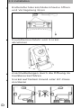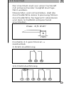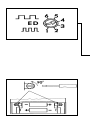
1
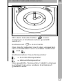
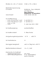
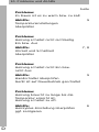
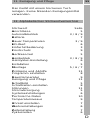
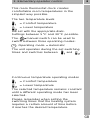
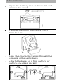
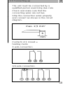
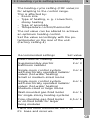
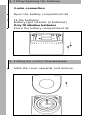
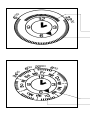
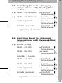
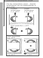
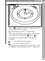
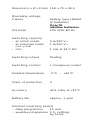
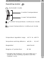
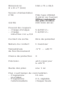
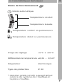
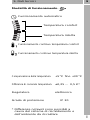
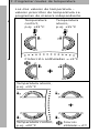
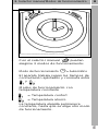
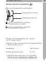
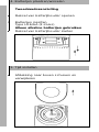
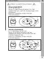
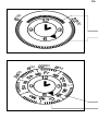
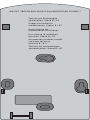
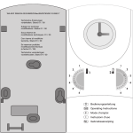
D
Bedienungsanleitung
GB
Operating Instructions
F
Mode d’emploi
I
Instruzioni d’uso
E
Instrucciones de empleo
NL
Gebruiksaanwijzing
1.
Inhaltsangabe
2
1.
Inhalt
Seite
2.
Einfachstbedienung
3
3.
Installationshinweise
4
3.1
Installation
5
3.2
Anschluß
5
3.3
Heizzyklus-Einstellung/Montage
6
4.
Batterie einsetzen/wechseln
7
5.
Aktuelle Uhrzeit einstellen
7
6.
Schaltzeiten einstellen
8
7.
Temperaturniveaus einstellen
9
8.
Handschalter/Betriebsarten
9
9.
Technische Daten
10
10.
Probleme und Abhilfe
11
11.
Reinigung und Pflege
11
12.
Alphabetisches Stichwortverzeichnis 11
Graues Feld kennzeichnet den Bereich
des Anwenders
D
2. Einfachstbedienung
3
Diese Raumthermostatuhr sorgt auf
einfache Art für eine behagliche Raumtemperatur.
Die beiden Temperaturniveaus
= Komforttemperatur
= Absenktemperatur
werden mit den zugeordneten Drehknöpfen
eingestellt.
Einstellbar zwischen 5 °C und 30 °C.
Mit dem Handschalter
kann zwischen
3 Betriebsarten gewählt werden:
Betriebsart
= Automatik
Das Gerät arbeitet nach den eingestellten
Schaltzeiten und schaltet zwischen
und
.
Betriebsarten Dauertemperatur
= Komforttemperatur
= Absenktemperatur
Die gewählte Temperatur bleibt solange
konstant bis eine andere Betriebsart
gewählt wird.
Bedenken Sie bei der Festlegung der
Schaltzeiten, daß die Heizung eine gewisse
Zeit benötigt, um die gewünschte Temperatur zu erreichen.
D
3. Installationshinweise
4
Die Montage/Installation muß von einer Fachkraft
mit entsprechender Sorgfalt durchgeführt werden.
Vor der Montage Heizungsanlage ausschalten.
Überprüfen und sicherstellen, daß die Anschlußdrähte keine Spannung führen.
Hinweise zur Montage:
– nur PVC-Mantelleitung (Massivdraht) für die
Installation verwenden
– nur auf nicht leitfähigem, ebenem und festem
Untergrund montieren
– nur für den Einsatz bei Umgebungsbedingungen mit üblicher Verunreinigung geeignet
– bei sachgemäßer Montage nach VDE 0100
Teil 40, können die dann noch berührbaren
Teile als doppelt isoliert (Schutzklasse II)
angesehen werden
Hinweise für den Betrieb:
Die Elektronik dieses Gerätes ist gegen Störungen von außen weitgehend geschützt. Es ist jedoch zu beachten – je nach Montageart – daß
der Netzspannung extrem starke Störspannungsspitzen überlagert sein können. Auch beim
Schalten von Spulen, z. B. Magnetventile,
Schütze, treten Störungen auf, die ein elektronisches Gerät trotz aller internen Schutzmaßnahmen beeinflußen können.
Um größtmögliche Betriebssicherheit zu gewährleisten, müssen beim Anschluß folgende Details
beachtet werden:
– bei größeren Anlagen ist es erforderlich,
Spulen, z. B. Magnetventile, Schütze, die
direkt vom Gerät geschaltet werden, mit
einem passenden Varistor oder RC-Glied
zu entstören
– werden induktive Gleichspannungsverbraucher geschaltet, muß eine Löschdiode dazugeschaltet werden
– induktive wie auch kapazitive Lasten, stellen
für die Ausgangskontakte eine besondere
Beanspruchung dar.
Prüfen Sie im Einzelfall, ob der Einbau
– eines Trennrelais oder Schütz bzw.
– eines Netzentstörfilters – z. B. Typ
NEF 2.-1,0 A Fa. Murr – angebracht ist.
D
3.1 Installation
Batteriefachdeckel/Abdeckhaube öffnen
und Verriegelung lösen
Raumthermostatuhr vom Sockel
abnehmen
Anschlußleitungen durch die Öffnung im
Gerätesockel führen
Sockel auf festem Grund oder UP-Dose
montieren
D
3.2 Anschluß
5
Der Anschluß muß von einer Fachkraft
mit entsprechender Sorgfalt durchgeführt werden.
Überprüfen und sicherstellen, daß die
Anschlußdrähte keine Spannung führen.
Anschlußdrähte fachgerecht abisolieren
und dem Schaltbild entsprechend
anschließen.
max. 2,5 mm2
6
mm
Kontakte 4-5 geschlossen =
Heizbetrieb
2-Draht-Ausführung
3/4-Draht-Ausführung
D
3.3 Heizzyklus-Einstellung/Montage
6
Die Heizzyklus-Einstellung (ED-Wert)
dient zur Anpassung an die Regelstrecke.
Diese wird beeinflußt von:
– Raumgröße
– Art der Heizung, z. B. Konvektoren,
Etagenheizungen
– Montageart
– Temperaturregler/Thermostat
Damit eine optimale Heizungsregelung
erreicht wird, kann der Einstellwert
verändert werden.
Auf der Rückseite des Gerätes mit dem
Potentiometer den entsprechenden Wert
einstellen.
(Werkseinstellung 4)
Einstellungsempfehlungen
Einstellwert
Elektrodirektheizung
1 oder 2
Badezimmerzusatzheizkörper elektr.
2 oder 3
Einzelraumregelung
3 oder 4
mit elektrisch betriebenen Heizkörperventilen (Warmwasserheizung)
Kleine bis mittlere Räume
Einzelraumregelung
4 oder 5
mit elektrischbetriebenen Heizkörperventilen (Warmwasserheizung)
Mittlere bis große Räume
Wandgaskessel für Etagenheizungen
4 oder 5
Standgaskessel oder Ölkessel 4,5 oder 6
für größere Wohneinheiten
Raumthermostatuhr auf Sockel stecken
und wieder verriegeln.
D
4. Batterien einsetzen/wechseln
2-Draht-Ausführung
Batteriefachdeckel öffnen
Batterien einsetzen
Batterietyp LR6/AA (2 Stück)
Nur Alkaline Batterien verwenden.
Batteriefachdeckel schließen
5. Aktuelle Uhrzeit/Wochentag einstellen
Abdeckung nach oben schieben und
abnehmen
D
5. Aktuelle Uhrzeit/Wochentag einstellen
7
Nur in Pfeilrichtung drehen
Tagesschaltuhr
z. B. 14.00 Uhr
Ring in Pfeilrichtung drehen bis
gewünschte Stunde mit Markierungspfeil übereinstimmt.
Exakte Einstellung erfolgt mit dem
Minutenzeiger.
Wochenschaltuhr
z. B. Dienstag 14.00 Uhr
Ring in Pfeilrichtung drehen bis
gewünschter Wochentag im Bereich
des Markierungspfeiles steht.
Exakte Einstellung erfolgt mit dem
Minutenzeiger.
D
6. Schaltzeiten einstellen
8
6.1 Schaltzeiten für den Temperaturwechsel bei Tagesschaltuhr
z. B. 06.00 Uhr – 22.00 Uhr = Komforttemperatur
z. B. 22.00 Uhr – 06.00 Uhr = Absenktemperatur
Segmente innen
= Absenktemperatur
Segmente außen
= Komforttemperatur
1 Segment = 15 Minuten
6.2 Schaltzeiten für den Temperaturwechsel bei Wochenschaltuhr
z. B. Montag - Freitag
06.00 Uhr – 22.00 Uhr = Komforttemperatur
22.00 Uhr – 06.00 Uhr = Absenktemperatur
Samstag - Sonntag
06.00 Uhr – 24.00 Uhr = Komforttemperatur
24.00 Uhr – 06.00 Uhr = Absenktemperatur
Segmente innen
= Absenktemperatur
Segmente außen
= Komforttemperatur
1 Segment = 1 Stunde
D
7. Temperaturniveaus einstellen
Die beiden Temperaturwerte –
Solltemperaturen werden unabhängig
voneinander eingestellt.
Komforttemperatur
z. B. +22 °C
Absenktemperatur
z. B. +15 °C
Frostschutz = +5°C
❄
Absenktemperatur
z. B. +15 °C
Komforttemperatur
z. B. +22 °C
D
❄
Frostschutz
= +5°C
8. Handschalter/Betriebsarten
9
Mit dem Handschalter
kann
zwischen 3 Betriebsarten gewählt
werden:
Betriebsart
= Automatik
Das Gerät arbeitet nach den eingestellten Schaltzeiten und schaltet zwischen
und
.
Betriebsarten Dauertemperatur
= Komforttemperatur
= Absenktemperatur
Die gewählte Temperatur bleibt solange
konstant bis eine andere Betriebsart
gewählt wird.
D
Maße H x B x T (mm)
Betriebsspannung
2-Draht
3/4-Draht
Schaltleistung
– bei ohmscher Last
– bei induktiver Last
cos ϕ 0,6
– min.
158 x 75 x 36,5
Batterie, Typ LR6/AA
(2 Stück)
Nur Alkaline
Batterien verwenden
230 V/50-60 Hz
5 A/250 V~
1 A/250 V~
1 mA bei 24 V DC
Schaltausgang
potentialfrei
Schaltkontakt
1 Wechsler
Umgebungstemperatur -5 °C … +45 °C
Schutzklasse
II
Ganggenauigkeit
±2,5 s/Tag bei +25 °C
Batterielebensdauer
ca. 1 Jahr
Kürzeste Schaltzeit
– Tagesprogramm
– Wochenprogramm
15 min
2 h, einstellbar
jede Stunde
9. Technische Daten
10
Betriebsarten
Automatikbetrieb
Komforttemperatur
Absenktemperatur
Dauerbetrieb Komforttemperatur
Dauerbetrieb Absenktemperatur
Temperaturregelbereich
+5 °C bis +30 °C
Temperaturschaltdifferenz ±0,25 … 0,5 K*
Regler
elektronisch
Schutzart
IP 20
* Größere Abweichungen sind bedingt
durch das Heizsystem und den beheizten
Raum möglich
D
10. Probleme und Abhilfe
Seite
Probleme:
Im Raum ist es zu warm bzw. zu kalt
Abhilfe:
Temperatureinstellungen
überprüfen
9
Probleme:
Heizung schaltet nicht rechtzeitig
Ein bzw. Aus
Abhilfe:
Uhrzeit und Schaltzeit
überprüfen
7, 8
Probleme:
Heizung schaltet nicht Ein bzw.
nicht Aus
Abhilfe:
Handschalter überprüfen
Gerät ist auf Dauerbetrieb geschaltet
9
Probleme:
Heizung braucht zu lange bis die
Temperatur erreicht ist.
Heizung schaltet zu oft.
Abhilfe:
Heizzyklus-Einstellung überprüfen
ggf. korrigieren
D
6
11. Reinigung und Pflege
11
Das Gerät mit einem trockenen Tuch
reinigen. Keine ätzenden Reinigungsmittel
verwenden.
12. Alphabetisches Stichwortverzeichnis
Stichwort
Anschlüsse
Automatikbetrieb
Batterie
Dauer-Temperaturen
Seite
5
3/8/9
7
3/9
ED-Wert
Einfachstbedienung
6
3
Frostschutz
9
Gerätesockel
Heizbetrieb
Heizzyklus-Einstellung
Installation
Montage
5
3/8/9
6
5
5/6/7
Probleme und Abhilfe
Programm einstellen
11
8
Raumtemperatur
Reinigung und Pflege
9
11
Schaltbild
Schaltzeiten einstellen
Störungen
Stromversorgung
Systemeinstellungen
5
8
11
5
6
Technische Daten
Temperaturniveaus
10
9
Uhrzeit einstellen
7
Werkseinstellungen
6
Zeiteinstellung
Zykluszeiten
7
6
D
1.
List of contents
2
1.
List of contents
Page
2.
Elementary operator control
3
3.1
Installation
4
3.2
Connecting up
4
3.3
Heating cycle setting/assembly
5
4.
Fitting/replacing the battery
6
5.
Setting the correct time
6
6.
Setting the switching times
7
7.
Setting the temperature levels
8
8.
Manual switch/operating modes
8
9.
Technical data
9
10.
Problems and remedies
10
11.
Cleaning and maintenance
10
12.
Alphabetical subject-index
10
Grey area indicates user range
GB
2. Elementary operator control
3
This room thermostat clock creates
comfortable room temperatures in the
simplest way possible.
The two temperature levels
= Comfort temperature
= Lower temperature
are set with the appropriate dials.
Settings between 5 °C and 30 °C possible.
The
manual switch can be used to
switch between three operating modes:
Operating mode = Automatic
The unit operates during the set switching
times and switches between
and
.
Continuous temperature operating modes
= Comfort temperature
= Lower temperature
The selected temperature remains constant
until a different operating mode has been
selected.
Please remember when setting the
switching times that the heating system
requires a certain amount of time before
it reaches the desired temperature.
GB
3.1 Installation
Open the battery compartment lid and
release the catch
Remove the room thermostat clock
from its base
Feed the connection wires through the
opening in the unit’s base
Attach the base on a firm surface or
surface-mounted socket
3.2 Connecting up
4
The unit must be connected by a
qualified person exercising due care.
Check and make sure that the
connecting wires are not live.
Strip the connection wires properly
and connect as shown in the circuit
diagram.
max. 2,5 mm2
6
mm
Contacts 4-5 closed =
heating mode
2-wire connection
3/4-wire connection
GB
3.3 Heating cycle setting/assembly
5
The heating-cycle setting (CDF value) is
for adapting to the control range.
This is affected by:
– Room size
– Type of heating, e. g. convectors,
storey heating
– Type of assembly
– Temperature control/thermostat
The set value can be altered to achieve
an optimum heating control.
Set the value accordingly with the potentiometer on the rear of the unit.
(Factory setting 4)
Recommended settings
Set value
Direct electric heating
1 or 2
Supplementary electric
bathroom radiator
2 or 3
Single-room control system
3 or 4
with electrically operated radiator
valves (hot-water heating)
Small or medium-sized rooms
Single-room control system
4 or 5
with electrically operated radiator
valves (hot-water heating)
Medium-sized or large rooms
Wall-mounted gas-fired boiler
4 or 5
for single-storey heating systems
Free-standing gas-fired boiler
or oil-fired boiler for larger
living modules
4,5 or 6
Place the room thermostat clock on
it’s base and resecure.
GB
4. Fitting/replacing the batteries
2-wire connection
Open the battery compartment lid
Fit the batteries
Battery type LR6/AA (2 batteries)
Only fit alkaline batteries
Close the battery compartment lid
5. Setting the correct time/weekday
Slide the cover upwards and remove.
5. Setting the correct time/weekday
6
Only turn in the direction of the arrow
Day time switch
e. g. 14.00 h
Turn the ring in the direction of the
arrow until the desired hour is aligned
with the locating arrow.
The precise setting is made with the
minute hand.
Week time switch
e. g. Tuesday 14.00 h
Turn the ring in the direction of the
arrow until the desired week day is in
the area of the locating arrow.
The precise setting is made with the
minute hand.
GB
6. Setting the switching times
7
6.1 Switching times for changing
temperatures with the day time
switch
e. g. 06.00 – 22.00 hours
= Comforttemperature
e. g. 22.00 – 06.00 hours
= Lower
temperature
Inside segments
= Lower
temperature
Outside segments
= Comforttemperature
1 segment = 15 minutes
6.2 Switching times for changing
temperatures with the week time
switch
e. g. Monday - Friday
06.00 – 22.00 h
= Comforttemperature
22.00 – 06.00 h
= Lower
temperature
Saturday - Sunday
06.00 – 24.00 h
= Comforttemperature
24.00 – 06.00 h
= Lower
temperature
Inside segments
= Lower
temperature
Outside segments
= Comforttemperature
1 segment = 1 hour
GB
7. Switching the temperatures on/off
The two temperature values – desired
temperatures are set independently of
each other.
Comfort
temperature
e. g. +22 °C
Lower
temperature
e. g. +15 °C
Frost protection = +5°C
❄
Lower temperature
e. g. +15°C
Comfort temperature
e. g. +22°C
❄
Frost protection
= +5°C
8. Manual switch/operating modes
8
The
manual switch selects one of
three operating modes:
Operating mode = Automatic
The unit operates during the set times
and switches between
and
.
Continuous temperature operating
modes
= Comfort temperature
= Lower temperature
The selected temperature remains until
a different operating mode is selected.
GB
Dimensions H x W x D (mm) 158 x 75 x 36,5
Operating voltage
2 wires
3/4 wires
Switching capacity
– at ohmic loads
– at inductive loads
cos ϕ 0,6
– min.
battery, type LR6/AA
(2 batteries)
Only fit
alkaline batteries
230 V/50-60 Hz
5 A/250 V~
1 A/250 V~
1 mA at 24 V DC
Switching output
floating
Switching contact
1 changeover contact
Ambient temperature
-5 °C … +45 °C
Class of protection
II
Accuracy
±2,5 s/day at +25 °C
Battery life
approx. 1 year
Shortest switching period
– daily programme
15 min.
– weekley programme 2 h, settings
by hours
9. Technical data
9
Operating modes
Automatic mode
Comfort temperature
Lower temperature
Comfort temperature continuous mode
Lower temperature continuous mode
Temperature regulation range +5 °C to +30 °C
Temperature switching difference ±0,25 … 0,5 K*
Regulator
electronic
Degree of protection
IP 20
* Greater fluctuations are possible as a
result of the heating system and the
heated room
GB
10. Problems and remedies
Page
Problems:
The room is too hot or cold
Remedy:
Check temperature settings
8
Problems:
The heating system does not switch
on or off on time
Remedy:
Check time and switching
time
6, 7
Problems:
The heating system does not switch
on or off
Remedy:
Check the manual switch
Unit is switched to continuous mode
8
Problems:
The heating system takes too long to
reach the desired temperature.
The heating system switches too
frequently.
Remedy:
Check heating-cycle setting
correct if necessary
5
11. Cleaning and maintenance
10
Use a dry cloth to clean the unit.
Never use any caustic cleaning
agents.
12. Alphabetical subject-index
Key word
Automatic mode
Battery
CDF value
Cleaning and maintenance
Connections
Continuous temperatures
Cycle times
Diagram
Factory settings
Faults
Frost protection
Heating mode
Heating-cycle setting
Installation
Power supply
Problems and remedies
Programme setting
Page
3/7/8
6
5
10
4
8
5
4
5
10
8
3/7/8
5
4
6
10
7
Room temperature
8
Setting switching times
Setting the current time
System settings
7
6
5
Technical data
Temperature levels
Time setting
9
8
6
Unit base
4
GB
1.
Sommaire
2
1.
Sommaire
Page
2.
Mise en route
3
3.1
Installation
4
3.2
Raccordement
4
3.3
Réglage du temps de
cycle/montage
5
4.
Montage et changement des piles
6
5.
Réglage de l’heure et jour actuels
6
6.
Réglages des horaires de
commutation
7
7.
Réglages des températures par
niveau
8
8.
Sélecteur manuel/mode de
fonctionnement
8
9.
Caractéristiques techniques
9
10.
Problèmes et solutions/aide
10
11.
Nettoyage et entretien
10
12.
Liste alphabétique des fonctions
10
Les zones grisées sont les paragraphes
concernant l’utilisateur
F
2. Mise en route rapide
3
Ce thermostat d’ambiance à horloge
permet facilement d’avoir une température
ambiante confortable.
Les 2 niveaux de température
= Température confort
= Température réduit
Sont réglées au moyen d’un bouton.
La plage va de +5 °C à +30 °C.
Avec le sélecteur manuel
on peut
choisir entre 3 modes de fonctionnement:
Mode de service
= automatique
L’appareil travaille suivant la positions des
segments de l’horloge de programmation
et passe ainsi de la valeur réglée sur
à
celle de
.
Mode de fonctionnement permanent
= Température confort
= Température réduit
La température réglée reste active aussi
longtemps qu’un autre mode n’a pas été
choisi.
Rappelez-vous que lors des commutations,
il faut un certain temps pour atteindre la
température réglée souhaitée.
F
3.1 Installation
Enlever le capot contenant les piles
Enlever le thermostat d’ambiance
de son socle
Passer le câble de raccordement au travers
de l’ouverture située dans le socle
Fixer le socle solidement ou bien sur la
boite de raccordement
3.2 Raccordement
4
Le raccordement doit être fait par un
spécialiste professionnel compétent et
avec soins.
Vérifier et s’assurer que le câble de
raccordement n’est pas sous tension.
Dénuder la portion du câble nécessaire
et raccorder aux bornes suivant le
schéma suivant.
max. 2,5 mm2
6
mm
Entre la borne 4 et 5 le contact
se ferme = chauffage en marche
Raccordement 2 fils
Raccordement 3/4 fils
F
3.3 Réglage du cycle de fonctionnement et montage
5
Le réglage du cycle de fonctionnement
du chauffage (valeur Ed) sert à adapter le
système de régulation.
Il est influencé par:
– Le volume de la pièce
– Type de chauffage exemple
convecteur, etc..
– Genre de montage
– Régulateur de température
(proportionnel) ou thermostat
(tout ou rien)
Afin d’obtenir une régulation optimale,
il faut si nécessaire ajuster ce paramètre.
Au dos de l’appareil, régler le potentiomètre à la bonne valeur suivant exemple
ci-dessous (le réglage d’usine est à 4).
Types d’installation
valeurs de réglage
Chauffage électrique direct
convecteurs ou autres
Chauffage électrique direct
en salle de bain
1à2
2à3
Réglage de pièce individuelle
3à4
équipée de robinet thermostatique
(chauffage à eau chaude)
petit et moyen volume
Réglage de pièce individuelle
4à5
équipée de robinet thermostatique
chauffage à eau chaude
(moyen et gros volume)
Chaudière à gaz murale en
collectivité
Chaudière au sol à gaz ou au
fioul en grosse collectivité
4à5
4,5 á 6
Rembrocher le thermostat d’ambiance
sur son socle et le verrouiller
F
4. Installer les piles ou les changer
Raccordement 2 fils
Enlever le capot contenant les piles et
la languette de maintien
Mettre les piles de type LR6/AA (2 pièces)
Utiliser seulements des piles alcalines
Remettre la languette et le capot
5. Mettre à l’heure et au jour actuels
Tirer le capot horloge vers le haut en
le faisant glisser et l’enlever
5. Mettre à l’heure et au jour actuels
6
Tourner les aiguilles dans le sens
des aiguilles d’une montre.
Horloge à programme journalier
par exemple s’il est 14H00
Tourner et amener le disque dans le
sens des aiguilles d’une montre jusqu’à
l’heure du moment en face du triangle;
régler exactement à la minute en
tournant l’aiguille des minutes dans le
sens – à droite –.
Horloge à programme hebdomadaire
par exemple s’il est mardi 14H00
Tourner et amener le disque dans le
sens des aiguilles d’une montre
jusqu’au jour et heure du moment en
face du triangle; régler exactement à
la minute en tournant l’aiguille des
minutes dans le sens – à droite –.
F
6. Réglages des horaires de commutation
7
6.1 Horaires de commutation pour les
changements de température de
l’horloge journalière
ex: 06H00 – 22H00
= Température
confort
ex: 22H00 – 06H00
= Température
réduite
Segments vers l’intérieur = Température
réduite
Segments vers l’extérieur = Température
confort
1 Segment = 15 minutes
6.2 Horaires de commutation pour les
changements de température de
l’horloge hebdomadaire
ex: lundi à vendredi:
ex: 06H00 – 22H00
= Température
confort
ex: 22H00 – 06H00
= Températureréduite
ex: samedi et dimanche
06H00 – 24H00
= Température
confort
24H00 – 06H00
= Températureréduite
Segments vers l’intérieur = Température
réduite
Segments vers l’extérieur = Température
confort
1 Segment = 1 heure
F
7. Réglages des températures par niveau
Les 2 valeurs de température à régler
sont réglables indépendamment l’une
de l’autre.
Température
de confort
Exemple +22 °C
Température
réduite
Exemple +15 °C
Hors gel = +5°C
❄
Température réduite
Exemple +15°C
Température de confort
Exemple +22°C
❄
Hors gel
= +5°C
8. Sélecteur manuel et mode de fonctionnement
Avec le sélecteur manuel
pouvez choisir 3 modes de
fonctionnement:
8
vous
Mode de fonctionnement automatique
= Automatique
L’appareil travaille suivant les horaires
de commutation programmés et
commute sur
ou
.
Selecteur manuel en mode
température permanente
= Température de confort
= Température réduite
La température réglée choisie reste
jusqu’à ce qu’un autre mode de
fonctionnement soit choisi.
F
Dimensions
H x B x T (mm)
Tension d’alimentation
2 fils
3/4 fils
158 x 75 x 36,5
Piles type LR6/AA
(2 pièces non fournies)
Utiliser seulements
des piles alcalines
230 V/50-60 Hz
Pouvoir de coupure
– charge ohmique
– charge
inductive cos ϕ 0,6
5 A/250 V~
1 A/250 V~
Contact de sortie
libre de potentiel
Nature du contact
1 inverseur
Température
de fonctionnement
-5 °C … +45 °C
Classe de protection
II
Précision
±2,5 s/par jour
à +25 °C
Durée des piles
env. 1 an
Plus court temps de commutation
– Programme
15 min
journalier
– Programme
2 h, réglable
hebdomadaire
chaque heure
9. Caractéristiques techniques
9
Mode de fonctionnement
Mode automatique
Température confort
Température réduite
Température confort en permanence
Température réduit en permanence
Plage de réglage
+5 °C à +30 °C
Différentiel de température ±0,25 … 0,5 K*
Régulateur
électronique
Type de protection
IP 20
* des plus grands écarts peuvent arriver
selon le du système de chauffage et
la pièce chauffée.
F
10. Problèmes et solutions/aide
Problème:
Dans la pièce il fait trop chaud ou trop froid
Solutions/aides:
Vérifier le réglage des
températures désirées
8
Problème:
La chauffage ne coupe pas à temps à
l’enclenchement ou au déclenchement.
Solutions/aides:
Vérifier l’heure actuelle et les
heures de commutation
ainsi que les jours
6, 7
Problème:
La chauffage ne coupe pas à temps à
l’enclenchement ou au déclenchement.
Solutions/aides:
Vérifier le sélecteur manuel
il est peut être sur permanent
(EN ou HORS)
8
Problème:
La chauffage prend trop de temps pour
atteindre la température désirée
Solutions/aides:
Vérifier le réglage de cycle Ed et
corriger le éventuellement
5
11. Nettoyage et entretien
10
L’appareil doit être nettoyé avec un chiffon
sec. Il ne faut pas utiliser de produit de
nettoyage même adouci.
12. Liste alphabétique des fonctions
Sommaire
cette page
Alimentation
6
Caractéristiques techniques
Cycle de chauffage – réglage
9
5
Hors gel
8
Installation
4
Mise en service simplifiée
Mode chauffage
Montage
3
3/7
4
Nettoyage et entretien
Niveaux de température
10
8
Perturbations
Piles
Problèmes et solutions/aides
10
6
10
Raccordement
3/7/8
Réglages du programme
7
Réglage des horaires de commutation
7
Réglage du système
5
Réglage de l’heure
6
Réglages usine
5
Service automatique
Socle de l’appareil
Schéma de raccordement
Température ambiante
Températures permanentes
Temps de cycle
3/7/8
4
4
8
3/8
5
F
1.
Indice del contenuto
2
1.
Indice
Pagina
2.
Uso semplificato
3
3.1
Installazione
4
3.2
Collegamento
4
3.3
Montaggio/regolazione ciclo di riscaldamento 5
4.
Inserire/cambiare le pile
5.
Regolazione dell’orario attuale/giorno della settimana 6
6.
Regolazione dei periodi di comando
7
7.
Regolazione dei livelli di temperatura
8
8.
Comando manuale/modalità di funzionamento
8
9.
Dati tecnici
9
10.
Problemi e soluzioni
10
11.
Pulizia e manutenzione
10
12.
Indice alfabetico
10
6
Il campo grigio identifica le operazioni
eseguibili dall’utente
I
2. Uso semplificato
3
Questo cronotermostato per ambienti permette nel modo più semplice di mantenere sempre una temperatura ambiente piacevole.
I due livelli di temperatura
= Temperatura comfort
= Temperatura ridotta
vengono regolati mediante le due manopole
appositamente assegnate.
I livelli sono regolabili tra 5 °C e 30 °C.
Mediante il comando manuale
si
possono selezionare tre modalità di funzionamento:
Funzionamento
= Automatico
L’apparecchio lavora in base ai tempi scelti
commutando tra
e
.
Funzionamento con temperatura fissa
= Temperatura comfort
= Temperatura ridotta
La temperatura selezionata rimane fissa
fin quando non viene selezionata un’altra
modalità di funzionamento.
È necessario tenere presente che, a
secondo del tipo di riscaldamento,
fissando periodi di comando il riscaldamento impiega un determinato tempo
per raggiungere la temperatura desiderata.
I
3.1 Installazione
Aprire il coperchio dello scompartimento
pile ed allentare il bloccaggio
Rimuovere il cronotermostato dallo
zoccolo
Infilare i conduttori di collegamento
attraverso l’apertura situata nello
zoccolo dell’apparecchio
Montare lo zoccolo su di un basamento
fisso oppure su una presa da incasso
3.2 Collegamento
4
Il montaggio deve essere eseguito da
un elettricista qualificato con la
dovuta accuratezza.
Verificare ed accertare che i conduttori
di collegamento non siano sottoposti a
tensione elettrica.
Isolare in modo appropriato i conduttori
di collegamento e collegarli in conformità allo schema di collegamento.
max. 2,5 mm2
6
mm
Contatti 4-5 chiusi =
funzione riscaldamento
Collegamento a 2 fili
Collegamento a 3/4 fili
I
3.3 Montaggio/regolazione ciclo di riscaldamento
5
La regolazione del ciclo di riscaldamento
(valore di durata dell’inserimento) serve
per adeguare i periodi di regolazione.
Ciò viene influenzato da:
– dimensione dell’ambiente
– tipo di riscaldamento, p. es. termoconvettori, riscaldamento a zona per
appartamento o singolo piano
– tipo di montaggio
– regolatore di temperatura/termostato
Allo scopo di raggiungere un’ottima regolazione del riscaldamento, si può variare il valore di regolazione.
Regolare mediante il potenziometro situato sul lato posteriore dell’apparecchio il
rispettivo valore.
(Preimpostazione in fabbrica 4)
Raccomandazioni di regolazione
Valore di regolazione
Riscaldamento elettrico diretto
1 oppure 2
Elementi elettrici riscaldanti
supplementari in bagno
2 oppure 3
Regolazione ambienti singoli con val- 3 oppure 4
vole degli elementi riscaldanti azionate
elettricamente (riscaldamento acqua calda)
Ambienti piccoli e medi
Regolazione ambienti singoli con val- 4 oppure 5
vole degli elementi riscaldanti azionate
elettricamente (riscaldamento acqua calda)
Ambienti medi e grandi
Caldaia a gas de parete per
riscaldamento autonomo
Riscaldamento centralizzati a gas
oppure a nafta, edifici più grandi
4 oppure 5
4,5 oppure 6
Reinnestare il cronotermostato sullo
zoccolo e bloccarlo di nuovo.
I
4. Inserire cambiare le pile
Collegamento a 2 fili
Aprire il coperchio dello scompartimento pile
Inserire le pile
Tipo LR6/AA (2 pezzi Alkaline)
Chiudere il coperchio dello scompartimento pile
5. Regolazione dell’orario attuale/giorno della settimana
Spingere la calotta verso l’alto e
rimuoverla
5. Regolazione dell’orario attuale/giorno della settimana
6
Ruotare l’orologio solamente
in senso orario
Temporizzatore giornaliero
p. es. ore 14.00
Ruotare l’anello in senso orario fino
a quando l’orario desiderato non
corrisponde con la marcatura della
freccia.
La regolazione esatta viene eseguita
mediante la lancetta dei minuti.
Temporizzatore settimanale
p. es. martedi ore 14.00
Ruotare l’anello in senso orario fino a
quando il giorno della settimana
desiderato non si trova in prossimità
della marcatura della freccia
La regolazione esatta viene eseguita
mediante la lancetta dei minuti.
I
6. Regolazione dei periodi di comando
7
6.1 Periodi di comando per il cambio
di temperatura con il temporizzatore giornaliero
p. es. ore 06.00 – 22.00
= Temperatura
comfort
p. es. ore 22.00 – 06.00
= Temperatura
ridotta
Segmenti interni
= Temperatura
ridotta
Segmenti esterni
= Temperatura
comfort
1 segmento = 15 minuti
6.2 Periodi di comando per il cambio
di temperatura con il temporizzatore settimanale
p. es. Lunedì - Venerdì
ore 06.00 – 22.00
= Temperatura
comfort
ore 22.00 – 06.00
= Temperatura
ridotta
Sabato - Domenica
ore 06.00 – 24.00
= Temperatura
comfort
ore 24.00 – 06.00
= Temperatura
ridotta
Segmenti interni
= Temperatura
ridotta
Segmenti esterni
= Temperatura
comfort
1 segmento = 1 ora
I
7. Regolazione e disinserimento della temperatura
I valori di temperatura e le temperature
nominali vengono regolati indipendentemente tra di loro.
Temperatura
comfort
p. es. +22 °C
Temperatura
ridotta
p. es. +15 °C
Antigelo = +5°C
❄
Temperatura ridotta
p. es. +15 °C
Temperatura comfort
p. es. +22 °C
❄
Antigelo
= +5°C
8. Comando manuale/modalità di funzionamento
8
Mediante il comando manuale
si
possono selezíonare tre modalità di
funzionamento
Funzionamento
= Automatico
L’apparecchio lavora in base ai periodi
di comando regolati e commuta tra
e
.
Funzionamento con temperatura fissa
= Temperatura comfort
= Temperatura ridotta
La temperatura selezionata rimane
fissa finché non viene selezionata
un’altra modalità di funzionamento.
I
Dimensioni A x L x P (mm) 158 x 75 x 36,5
Alimentazione
2 fili
3/4 fili
Portata contatti
– carico ohmico
– carico induttivo
cos ϕ 0,6
– min.
Pile tipo LR6/AA
(2 pezzi Alkaline)
230 V/50-60 Hz
5 A/250 V~
1 A/250 V~
1 mA a 24 V DC
Contatti in uscita
potenziale libero
Contatto di comando
in commutazione
Temperatura ambiente
-5 °C … +45 °C
Classe di protezione
II
Precisione
±2,5 s/giorno a+25°C
Durata delle pile
ca. 1 anno
Periodo di comando più breve
– Programma giornaliero 15 min
– Programma settimanale 2 h
regolabile ogni ora
9. Dati tecnici
9
Modalità di funzionamento
Funzionamento automatico
Temperatura comfort
Temperatura ridotta
Funzionamento continuo temperatura comfort
Funzionamento continuo temperatura ridotta
Compensazione della temperatura
+5 °C fino +30 °C
Differenza di comando temperatura ±0,25 … 0,5 K*
Regolatore
Grado di protezione
elettronico
IP 20
* Differenze notevoli sono possibili a
causa del sistema di riscaldamento e
dell’ambiente da riscaldare
I
10. Problemi e soluzioni
Pagina
Problemi:
L’ambiente è troppo caldo oppure troppo
freddo
Soluzioni:
Verificare le regolazioni della
temperatura
8
Problemi:
Il riscaldamento non si inserisce oppure
si disinserisce tempestivamente
Soluzioni:
Verificare l’orario ed il
periodo di comando
6, 7
Problemi:
Il riscaldamento non si inserisce oppure
si disinserisce
Soluzioni:
Verificare il comando manuale
L’apparecchio è impostato sul
funzionamento fisso
8
Problemi:
Il riscaldamento impiega troppo tempo
per raggiungere la temperatura dovuta.
Il riscaldamento si aziona troppo spesso.
Soluzioni:
Verificare il ciclo di riscaldamento e se necessario
correggerlo
5
11. Pulizia e manutenzione
10
Pulire l’apparecchio con un panno asciutto.
Non usare detersivi corrosivi.
12. Indice alfabetico
Voce
Pagina
Alimentazione
Antigelo
4
8
Collegamento
Cura e pulizia
4
10
Dati tecnici
9
Funzionamento automatico
Funzionamento di riscaldamento
8
9
Installazione
4
Livelli di temperatura
8
Montaggio
5
Pile
Preimpostazioni in fabbrica
Problemi e rimedi
4
5
10
Regolazione del ciclo di riscaldamento
Regolazione dell’orario
Regolazione periodi
Regolazione periodi di comando
Regolazione programma
Regolazione del sistema
5
6
7
7
6
6
Temperatura ambiente
Temperatura continua
7
7
Uso semplificato
3
Zoccolo apparecchio
4
I
1.
Indice
2
1.
Indice
Página
2.
Manejo básico
3
3.1
Instalación
4
3.2
Conexión
4
3.3
Ajuste del ciclo de calefacción/montaje 5
4.
Colocación/sustitución de baterías
6
5.
Programar hora/día de semana actual
6
6.
Programar tiempos de conmutación
7
7.
Programar niveles de temperatura
8
8.
Selector manual/Modos de funcionamiento
8
9.
Datos técnicos
9
10.
Problemas y soluciones
10
11.
Limpieza y cuidado
10
12.
Indice alfabético de funciones
10
La banda gris indica la sección
del usuario
E
2. Manejo básico
3
Este cronotermostato proporciona de
forma simple una temperatura ambiente
agradable.
Los dos niveles de temperatura
= temperatura confort
= temperatura ahorro
permiten ajustarse entre 5 °C y 30 °C con
los respectivos botones de selección.
Con el selector manual
pueden
elegirse 3 modos de funcionamiento:
Modo de funcionamiento
= Automático
El aparato trabaja según los tiempos de
conmutación ajustados y conmuta entre
y
.
Modos de funcionamiento con
temperatura constante
= temperatura confort
= temperatura ahorro
La temperatura elegida permanece
constante, hasta que se elige otro modo
de funcionamiento.
Tenga en cuenta al fijar los tiempos de
conmutación, que la calefacción precisa
de cierto tiempo, para alcanzar la
temperatura deseada.
E
3.1 Instalación
Abrir la tapa del compartimiento de
baterías y soltar el seguro
Saque el cronotermostato de su base
Pasar los cables de conexión a través
del orificio de la base
Fijar la base a una superficie sólida o a
una caja de montaje empotrable
3.2 Conexión
4
La conexión debe ser ejecutada con
el debido cuidado por un técnico
cualificado.
Verificar y asegurar de que los cables
de conexión no conduzcan corriente..
Desaislar debidamente los cables de
conexión y conectarlos según se
muestra en el diagrama.
máx. 2,5 mm2
6
mm
Contactos 4-5 cerrados =
Función de calefacción
Conexión a 2 hilos
Conexión a 3/4 hilos
E
3.3 Ajuste del ciclo de calefacción/montaje
5
La regulación del ciclo de calefacción
(valor ED) sirve para fijar los tiempos de
encendido del sistema de calefacción.
Estos tiempos dependen:
– el tamaño de habitación
– Tipo del sistema de calefacción
(individual o colectiva)
– Lugar de instalación
– al regulador de temperatura/termóstato
El valor de regulación puede graduarse,
a fin de obtener una óptima regulación
de calefacción.
Ajustar el valor correspondiente con el
potenciómetro en la parte posterior del
aparato.
(Ajuste de fábrica 4)
Ajustes recomendados
Valor de ajuste
Calefacción eléctrica
1ó2
Radiadores eléctricos
suplementarios para baños
2ó3
Calefacción por agua caliente,
3ó4
controlada con electrovalvulas
en habitaciones pequeñas/medianas
Regulación de ambientes
4ó5
individuales con válvulas de
radiador de mando eléctrico
(calefacción de agua caliente),
habitaciones medianas y grandes
Calderas de gas de montaje mural 4 ó 5
para calefacciónes individuales
Calderas de gas verticales o
calderas de gas-oil para
viviendas más grandes
4,5 ó 6
Introducir el cronotermostato en la
base y aseguarlo
E
4. Colocación/sustitución de baterías
Conexión a 2 hilos
Abrir la tapa del compartimiento
de baterías
Colocar las baterías
Modelo de batería LR6/AA (2 unidades)
Sólo emplear baterias alcalinas
Cerrar la tapa del compartimiento
de baterías
5. Programar hora/día de semana actual
Deslizar la tapa hacia arriba y
quitarla
5. Programar hora/día de semana actual
6
Girar sólo en el sentido de la flecha
Reloj conmutador diario
p.ej. 14.00 horas
Girar el anillo en el sentido de la flecha,
hasta que la hora deseada coincida
con la flecha de marcación.
El ajuste exacto se lleva a cabo
moviendo las agujas.
Reloj conmutador semanal
p.ej. martes 14.00 horas
Girar el anillo en el sentido de la flecha,
hasta que el día de semana deseado
esté situado en la zona de la flecha de
marcación.
El ajuste exacto se lleva a cabo
moviendo las agujas.
E
6. Programar tiempos de conmutación
7
6.1 Tiempos de conmutación para el
cambio de temperatura con el
reloj conmutador diario
p.ej. 06.00 horas – 22.00 horas = Temperatura
confort
p.ej. 22.00 horas – 06.00 horas = Temperatura
ahorro
Segmentos interiores
= Temperatura
ahorro
Segmentos exteriores
= Temperatura
confort
1 segmento = 15 minutos
6.2 Tiempos de conmutación para el
cambio de temperatura con el
reloj conmutador semanal
p.ej. lunes - viernes
06.00 horas – 22.00 horas = Temperatura
confort
22.00 horas – 06.00 horas = Temperatura
ahorro
sábado - domingo
06.00 horas – 24.00 horas = Temperatura
confort
24.00 horas – 06.00 horas = Temperatura
ahorro
Segmentos interiores
= Temperatura
ahorro
Segmentos exteriores
= Temperatura
confort
1 segmento = 1 hora
E
7. Programar niveles de temperatura
Los dos valores de temperatura –
valores prescritos de temperatura se
programan de manera independiente.
Temperatura
confort,
p.ej. +22 °C
Temperatura
ahorro,
p.ej. +15 °C
Protección antiheladas = +5°C
❄
Temperatura ahorro,
p.ej. +15 °C
Temperatura confort,
p.ej. +22 °C
❄
Protección
antiheladas = +5°C
8. Selector manual/Modos de funcionamiento
8
Con el selector manual
pueden
elegirse 3 modos de funcionamiento:
Modo de funcionamiento
= Automático
El aparato trabaja según los tiempos de
conmutación ajustados y conmuta entre
y
.
Modos de funcionamiento con
temperatura constante
= Temperatura confort
= Temperatura ahorro
La temperatura elegida permanece
constante, hasta que se elige otro modo
de funcionamiento.
E
Medidas H x A x P (mm)
158 x 75 x 36,5
Tensión de funcionamiento
2 hilos
2 baterías, LR6/AA
sólo emplear
baterias alcalinas
3/4 hilos
230 V/50-60 Hz
Capacidad de conmutación
– con carga resistiva 5 A/250 V~
– con carga inductiva 1 A/250 V~
cos ϕ 0,6
– mín.
1 mA a 24 V CC
Salida de conmutación
libre de potencial
Contacto de conmutación
1 conmutado
Temperatura de uso
-5 °C hasta +45 °C
Clase de protección
II
Precisión de marcha
±2,5 s/a +25 °C
Duración de la batería approx. 1 año
Tiempo de respuesta mínima:
– programa diario
15 min
– programa semanal 2 h, ajustable
cada hora
9. Datos técnicos
9
Modos de funcionamiento
Funcionamiento automático
Temperatura confort
Temperatura ahorro
Funcionamiento continuo,
temperatura confort
Funcionamiento continuo,
temperatura ahorro
Rango de temperaturas de control
+5 °C hasta +30 °C
Diferencia de conmutación de temperatura
±0,25 hasta 0,5 K*
Regulador
electrónico
Grado de protección
IP 20
* Mayores desviaciones son posibles
según sea el sistema de calefacción
con que sea calentada la habitación.
E
10. Problemas y soluciones
Página
Problemas:
La habitación está muy caliente o muy fría
Soluciones:
Verificar los valores ajustados
8
Problemas:
La calefacción no se conecta o
desconecta a tiempo
Soluciones:
Verificar la hora y el tiempo
de conmutación
6, 7
Problemas:
La calefacción no se conecta o
desconecta
Soluciones:
Verificar el selector manual
El aparato está conmutado a
funcionamiento continuo
8
Problemas:
La calefacción tarda mucho en conseguir
la temperatura designada.
La calefacción se conecta demasiado a
menudo.
Soluciones:
Verificar el ajuste del ciclo
de calefacción, y corregirlo
en caso necesario
E
5
11. Limpieza y cuidado
10
Limpiar el aparato con un paño seco.
No utilizar ningún procedimiento corrosivo.
12. Indice alfabético de funciones
Palabra clave
Ajuste del ciclo de calefacción
Ajustes de fábrica
Ajustes del sistema
Página
5
5
5
Baterías
6
Conexión
4
Datos técnicos
Diagrama de conexiones
9
4
Funcionamiento automático
Funcionamiento de calefacción
Instalación
Limpieza y culdado
Manejo básico
Montaje
Niveles de temperatura
Problemas y soluciones
Programar hora
Programar tiempos
Programar tiempos de conmutación
Protección antiheladas
Temperatura ambiente
Temperaturas constantes
Tiempo de ciclos
Valor ED
3/7/8
3/7/8
4
10
3
4/5
8
10
6
6
7
8
8
3/8
5
5
E
1.
Inhoudsopgave
2
1.
Inhoudsopgave
Blz
2.
Eenvoudige funkties
3
3.1
Montage
4
3.2
Aansluiting
4
3.3
Verwarmcyclus instellen/monteren
5
4.
Batterij plaatsen/vervangen
6
5.
Tijd instellen
6
6.
Schakeltijden instellen
7
7.
Temperatuurniveau’s instellen
8
8.
Handschakelaar/bedrijfstoestanden
8
9.
Technische gegevens
9
10.
Probleemstelling en help-info
10
11.
Reinigen en onderhoud
10
12.
Steekwoorden verwijzing (alfabetisch) 10
Grijze gebied duidt de inhoudsopgave
voor de gebruiker aan
NL
2. Eenvoudige funkties
3
De kamerthermostaat zorgt op een eenvoudige manier voor een behaaglijke
kamertemperatuur.
Beide temperatuurniveau’s
= comforttemperatuur
= dalingstemperatuur
worden met de daarvoor bestemde draaiknop ingesteld.
Instelbaar tussen 5 °C en 30 °C.
Met de handschakelaar
kan tussen
3 bedrijfstoestanden gekozen worden:
Bedrijfstoestand
= Automatisch
Het apparaat werkt volgens de ingestelde
schakeltijden en schakelt tussen
en
.
Bedrijfstoestanden continuetemperatuur
= comforttemperatuur
= dalingstemperatuur
De gekozen temperatuur blijft zolang konstant totdat er een andere bedrijfstoestand
wordt gekozen.
Denk eraan bij het instellen van de schakeltijden, dat de verwarming een zekere tijd
nodig heeft om de gewenste temperatuur te
bereiken.
NL
3.1 Montage
Deksel van batterijhouder openen en
vergrendeling verwijderen
kamerthermostaat van de sokkel nemen
Aansluitingen door de opening in de
sokkel van het apparaat steken
Sokkel op een stevige ondergrond of
inbouwdoos monteren
3.2 Aansluiting
4
De aansluiting moet door een vakman
met zorgvuldigheid uitgevoerd worden.
Controleren en zekerstellen dat de
aansluitdraden geen spanning voeren.
Aansluitdraden vakbekwaam isoleren
en het aansluitschema overeenkomstig
aansluiten.
max. 2,5 mm2
6
mm
Kontakten 4-5 gesloten =
verwarmen
Tweedraadsaansluiting
3/4 draadsaansluiting
NL
102
101
3.3 Verwarm-cyclus instellen/monteren
5
De verwarmingscyclus – instelling
(ED-waarde) dient ter aanpassing aan de
regeling, deze wordt beinvloed door:
– grootte van de ruimte
– soort verwarming, bijv. radiatoren,
stadsverwarming
– manier van montage
– temperatuurregelaar/thermostaat
Zodat er een optimale verwarmingsregeling bereikt kan worden, kan de
instelwaarde veranderd worden.
Aan de achterkant van het apparaat kunt
u met de potentiometer de passende
waarde instellen.
(Werkingsinstelling 4)
Instelaanbeveling
Instelwaarde
Electrische verwarming
1 of 2
Electrische badkamerverwarming
2 of 3
Ruimteregeling
met elektrische ventielen
(warmwaterverwarming)
middelkleine ruimten
3 of4
Ruimteregeling
met elektrische ventielen
(warmwaterverwarming)
middelgrote ruimten
4 of 5
Wandketel voor gas
4 of 5
Gas- of olie gestookte
ketel voor grotere
wooneenheden
4,5 of 6
kamerthermostaat op sokkel plaatsen
en weer vergrendelen.
NL
4. Batterijen plaatsen/wisselen
Tweedraadsaansluiting
Deksel van batterijhouder openen
Batterijen inzetten
Type LR6/AA (2 stuks)
Alleen alkaline batterijen gebruiken
Deksel van batterijhouder sluiten
5. Tijd instellen
Afdekking naar boven schuiven en
verwijderen
5. Tijd instellen
6
Alleen in pijlrichting draaien
Dagschakelklok
b. v. 14.00 uur
Ring in pijlrichting draaien tot het
gewenste uur met de markerings overeenkomt.
Exacte instelling volgt met de
minutenwijzer.
Weekschakelklok
b. v. dinsdag 14.00 uur
Ring in richting draaien tot de
gewenste dag in het bereik van de
markeringspeil ligt.
Exacte instelling volgt met de
minutenwijzer.
NL
106
105
6. Schakeltijden instellen
7
6.1 Schakeltijden voor de temperatuurwissel bij dagschakelklokken
b. v. 06.00 uur – 22.00 uur = comforttemperatuur
b. v. 22.00 uur – 06.00 uur = dalingstemperatuur
segmenten binnen
= dalingstemperatuur
segmenten buiten
= comforttemperatuur
1 segment = 15 minuten
6.2 Schakeltijden voor de temperatuurwissel bij weekschakelklokken
b. v. maandag - vrijdag
06.00 uur – 22.00 uur = comforttemperatuur
22.00 uur – 06.00 uur = dalingstemperatuur
zaterdag - zondag
06.00 uur – 24.00 uur = comforttemperatuur
24.00 uur – 06.00 uur = dalingstemperatuur
segmenten binnen
= dalingstemperatuur
segmenten buiten
= comforttemperatuur
1 segment = 1 uur
NL
7. Temperatuurniveau’s instellen
De beide temperatuurwaarden –
gewenste temperaturen worden
onafhankelijk van elkaar ingesteld.
Comforttemperatuur
b. v. +22 °C
Dalingstemperatuur
b. v. +15 °C
Vorstbescherming = +5°C
❄
Dalingstemperatuur
b. v. +15 °C
Comforttemperatuur
b. v. +22 °C
❄
Vorstbescherming
= +5°C
8. Handschakelaar/bedrijfstoestanden
8
Met de handschakelaar
kan tussen
3 bedrijfstoestanden gekozen worden:
Bedrijfstoestand
= automatisch
Het apparaat werkt volgens de ingestelde schakeltijden en schakelt tussen
en
.
Bedrijfstoestanden duurtemperatuur
= comforttemperatuur
= dalingstemperatuur
De gekozen temperatuur blijft zolang
konstant totdat een andere bedrijftoestand gekozen wordt.
NL
Grootte H x B x D (mm)
Voedingsspanning
2-draads
3/4-draads
158 x 75 x 36,5
Batterij, type LR6/AA
(2 stuks)
Alleen alkaline
batterijen gebruiken
230 V/50-60 Hz
Schakelvermogen
– bij ohmse belasting
5 A/250 V~
– bij induktieve belasting 1 A/250 V~
cos ϕ 0,6
– min.
1 mA bij 24 V DC
Schakeluitgang
potentiaalvrij
Schakelkontakt
1 wisselkontakt
Omgevingstemperatuur
-5 °C … +45 °C
Beschermklasse
II
Loopnauwkeurigheid
±2,5 s/dag bij +25 °C
Levensduur batterij
ca. 1 jaar
Kortste schakeltijd
– dagprogramma
– weekprogramma
15 min
2 uur, elk uur
instelbaar
9. Technische gegevens
9
Bedrijfssoorten
automatisch
comforttemperatuur
dalingstemperatuur
comforttemperatuur
dalingstemperatuur
Temperatuurregelbereik
+5 °C tot +30 °C
Temperatuurschakelverschil ±0,25 … 0,5 K*
Regelaar
electronisch
Bescherming
IP 20
* Grotere afwijkingen zijn mogelijk door het
verwarmingssysteem of de te verwarmen
ruimte
NL
10. Probleemstelling en help-info
Blz
Probleem:
Het is te warm resp. te koud in de ruimte
Help-info:
Temperatuurinstellingen
controleren
8
Probleem:
Verwarming schakelt niet op tijd
AAN resp. UIT
Help-info:
Tijd en schakeltijd
controleren
6, 7
Probleem:
Verwarming schakelt niet
AAN resp. UIT
Help-info:
Handschakelaar controleren
Apparaat is op duur geschakeld
8
Probleem:
Verwarming heeft te veel tijd nodig om
de temperatuur te bereiken.
Verwarming schakelt te snel.
Help-info:
Verwarmcyclus-instelling controleren
Corrigeren
5
11. Reinigen en onderhoud
10
Het apparaat met een droge doek reinigen.
Geen bijtende schoonmaakmiddelen
gebruiken.
12. Steekwoorden verwijzing (alfabetisch)
Steekwoorden
Aansluiting
Apparaten sokkel
Automatisch programmaverloop
Batterij
Continue-temperaturen
Cyclustijden
Blz
4
4
3/7/8
6
3/8
5
ED-waarde
Eenvoudigste bediening
5
3
Installatie
Instellen van tijd
4
6
Montage
4/5
Problemen en help-info
Programmeren
10
7
Ruimtetemperatuur
Reinigen en onderhoud
8
10
Schakelbeeld
Schakeltijden instellen
Storingen
Stroomverzorging
Systeeminstellingen
4
7
10
6
5
Technische gegevens
Temperatuurniveau’s
Tijd instellen
9
8
5
Verwarmen
Verwarmcyclus-instellen
Vorstbescherming
Werkingsinstelling
3/7
5
8
5
NL
WA-EKF 3662/08.98/S:MMS/D:Bau/98/00435/80.10.0885.7
Technische Änderungen
vorbehalten. Stand 8 / 97
Subject to technical
modifications. Status 8 / 97
Sous réserve de
modifications techniques
Con riserva di modifiche
tecniche. Stand 8 / 97
Se reservan posibles modificaciones técnicas
(a fecha 8 / 97)
Technische veranderingen
voorbehouden. Stand 8 / 97