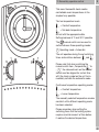
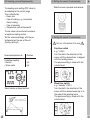
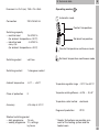
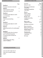
1
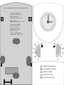
WA-EKF 3950/04.00/S:MMS/D:Bau/99/00763/80.10.0953.7
Technische Änderungen
vorbehalten. Stand 01 / 00
Subject to technical
modifications. Status 01 / 00
Sous réserve de
modifications techniques. 01 / 00
Con riserva di modifiche
tecniche. Stand 01 / 00
Se reservan posibles
modificaciones técnicas
(a fecha 01 / 00)
Technische veranderingen
voorbehouden. Stand 01 / 00
D
Bedienungsanleitung
GB
Operating Instructions
F
Mode d’emploi
I
Instruzioni d’uso
NL
Gebruiksaanwijzing
1.
Inhaltsangabe
2
1.
Inhalt
Seite
2.
Einfachstbedienung
3
3.
Hinweise zur Installation
4
3.1
Installation
5
3.2
Anschluß
5
3.3
Heizzyklus-Einstellung/Montage
6
4.
Aktuelle Uhrzeit einstellen
6
5.
Schaltzeiten einstellen
7
6.
Temperaturniveaus einstellen
8
7.
Handschalter/Betriebsarten
8
8.
Technische Daten
9
9.
Fragen und Antworten
10
10.
Reinigung und Pflege
10
11.
Stichwortverzeichnis alphabetisch
10
Graues Feld kennzeichnet den Bereich
des Anwenders
D
2. Einfachstbedienung
3
Diese Raumthermostatuhr sorgt auf
einfache Art für eine behagliche Raumtemperatur.
Die beiden Temperaturniveaus
= Komforttemperatur
= Absenktemperatur
werden mit den zugeordneten Drehknöpfen
eingestellt.
Einstellbar zwischen 1 und 6.
Mit dem Handschalter
kann zwischen
3 Betriebsarten gewählt werden:
Betriebsart
= Automatik
Das Gerät arbeitet nach den eingestellten
Schaltzeiten und schaltet zwischen
und
.
Bitte beachten Sie, daß beim Betätigen
des Handschalters aus der Position
„Temperatur
“ auf die Position „
“
kurzzeitig die Farbmarkierung des Handschalters mit dem Uhrensymbol am Gerät
in Deckung gebracht wird, damit die
Automatik sofort aktiviert wird.
Betriebsarten Dauertemperatur
= Komforttemperatur
= Absenktemperatur
Die gewählte Temperatur bleibt solange
konstant bis eine andere Betriebsart
gewählt wird.
Bedenken Sie bei der Festlegung der
Schaltzeiten, daß die Heizung eine gewisse
Zeit benötigt, um die gewünschte Temperatur zu erreichen.
D
3. Hinweise zur Installation
4
Die Montage/Installation muss von einer Fachkraft
mit entsprechender Sorgfalt durchgeführt werden.
Vor der Montage Heizungsanlage ausschalten.
Überprüfen und sicherstellen, dass die Anschlußdrähte keine Spannung führen.
Hinweise zur Montage:
– nur PVC-Mantelleitung (Massivdraht) für die
Installation verwenden
– nur auf nicht leitfähigem, ebenem und festem
Untergrund montieren
– nur für den Einsatz bei Umgebungsbedingungen mit üblicher Verunreinigung geeignet
– bei sachgemässer Montage nach VDE 0100
Teil 40, können die dann noch berührbaren
Teile als doppelt isoliert (Schutzklasse II)
angesehen werden
Hinweise für den Betrieb:
Die Elektronik dieses Gerätes ist gegen Störungen von aussen weitgehend geschützt. Es ist jedoch zu beachten – je nach Montageart – dass
der Netzspannung extrem starke Störspannungsspitzen überlagert sein können. Auch beim
Schalten von Spulen, z. B. Magnetventile,
Schütze, treten Störungen auf, die ein elektronisches Gerät trotz aller internen Schutzmassnahmen beeinflussen können.
Um grösstmögliche Betriebssicherheit zu gewährleisten, müssen beim Anschluss folgende Details
beachtet werden:
– bei grösseren Anlagen ist es erforderlich,
Spulen, z. B. Magnetventile, Schütze, die
direkt vom Gerät geschaltet werden, mit
einem passenden Varistor oder RC-Glied
zu entstören
– werden induktive Gleichspannungsverbraucher geschaltet, muss eine Löschdiode dazugeschaltet werden
– induktive wie auch kapazitive Lasten, stellen
für die Ausgangskontakte eine besondere
Beanspruchung dar.
Prüfen Sie im Einzelfall, ob der Einbau
– eines Trennrelais oder Schütz bzw.
– eines Netzentstörfilters – z. B. Typ
NEF 2.-1,0 A Fa. Murr – angebracht ist.
D
3.1 Installation
Abdeckhaube öffnen und Verriegelung
lösen
3.2 Anschluss
5
Der Anschluss muss von einer
Fachkraft mit entsprechender Sorgfalt
durchgeführt werden.
Überprüfen und sicherstellen, dass die
Anschlussdrähte keine Spannung führen.
Anschlussdrähte fachgerecht abisolieren
und dem Schaltbild entsprechend
anschliessen.
max. 2,5 mm2
Gerät vom Sockel abnehmen
6
mm
Kontakte 4-5 geschlossen =
Heizbetrieb
Anschluss Fussbodenfühler (Klemmen 6-7)
! Leitung in mind. 10 cm Abstand zu
Netzleitungen verlegen.
Anschlussleitungen durch die Öffnung im
Gerätesockel führen
Sockel auf festem Grund oder UP-Dose
montieren
D
Hinweis: Wenn die Fühlerleitung unterbrochen, bzw. der Fühler defekt ist, ist der
Heizbetrieb auf jeden Fall gewährleistet.
• Leitung unterbrochen (hochohmig) = Dauerheizbetrieb (Kesselsteuerung)
Für bestimmte Temperaturwerte können
Sie einen Festwiderstand anschliessen:
• Festwiderstand mit 25,0 kΩ
=ˆ ca. + 10° C
• Festwiderstand mit 10,0 kΩ
=ˆ ca. + 25° C
• Festwiderstand mit 6,8 kΩ
=ˆ ca. + 35° C
D
3.3 Heizzyklus-Einstellung/Montage
Die Heizzyklus-Einstellung (ED-Wert)
dient zur Anpassung an die Regelstrecke.
Diese wird beeinflusst von:
– Raumgrösse
– Art der Heizung, z. B. Konvektoren,
Etagenheizungen
– Montageart
– Temperaturregler/Thermostat
Damit eine optimale Heizungsregelung
erreicht wird, kann der Einstellwert
verändert werden.
Auf der Rückseite des Gerätes mit dem
Potentiometer den entsprechenden Wert
einstellen.
(Werkseinstellung 4)
Empfehlung für
Einstellwert
Fussbodenheizung
• Elektro
• Warmwasser
4-5
5-6
Gerät auf Sockel stecken und wieder
verriegeln.
D
4. Aktuelle Uhrzeit/Wochentag einstellen
6
Abdeckung nach oben schieben und
abnehmen
4. Aktuelle Uhrzeit/Wochentag einstellen
Nur in Pfeilrichtung drehen
Tagesschaltuhr
z. B. 14.00 Uhr
Ring in Pfeilrichtung drehen bis
gewünschte Stunde mit Markierungspfeil übereinstimmt.
Exakte Einstellung erfolgt mit dem
Minutenzeiger.
Wochenschaltuhr
z. B. Dienstag 14.00 Uhr
Ring in Pfeilrichtung drehen bis
gewünschter Wochentag im Bereich
des Markierungspfeiles steht.
Exakte Einstellung erfolgt mit dem
Minutenzeiger.
D
5. Schaltzeiten einstellen
7
5.1 Schaltzeiten für den Temperaturwechsel bei Tagesschaltuhr
(Typ 505)
z. B. 06.00 Uhr – 22.00 Uhr = Komforttemperatur
z. B. 22.00 Uhr – 06.00 Uhr = Absenktemperatur
Segmente innen
= Absenktemperatur
Segmente außen
= Komforttemperatur
1 Segment = 15 Minuten
5.2 Schaltzeiten für den Temperaturwechsel bei Wochenschaltuhr
(Typ 555)
z. B. Montag - Freitag
06.00 Uhr – 22.00 Uhr = Komforttemperatur
22.00 Uhr – 06.00 Uhr = Absenktemperatur
Samstag - Sonntag
06.00 Uhr – 24.00 Uhr = Komforttemperatur
24.00 Uhr – 06.00 Uhr = Absenktemperatur
Segmente innen
= Absenktemperatur
Segmente außen
= Komforttemperatur
1 Segment = 1 Stunde
D
6. Temperaturniveaus einstellen
7. Handschalter/Betriebsarten
8
Die beiden Temperaturwerte –
Solltemperaturen werden unabhängig
voneinander eingestellt.
Komforttemperatur
Absenktemperatur
Frostschutz, ca. +10°C
❄
Mit dem Handschalter
kann
zwischen 3 Betriebsarten gewählt
werden:
Betriebsart
= Automatik
Das Gerät arbeitet nach den eingestellten Schaltzeiten und schaltet zwischen
und
.
Betriebsarten Dauertemperatur
= Komforttemperatur
= Absenktemperatur
Die gewählte Temperatur bleibt solange
konstant bis eine andere Betriebsart
gewählt wird.
D
D
8. Technische Daten
Masse H x B x T (mm) 158 x 75 x 36,5
Anschluss
Schaltleistung
– bei ohmscher Last
– bei induktiver Last
cos ϕ 0,6
230 V/50-60 Hz
9
Betriebsarten
Automatikbetrieb
Komforttemperatur
16 A/250 V~
(bei Umgebungstemperatur < 30 °C)
14 A/250 V~
(bei Umgebungstemperatur < 45°C)
4 A/250 V~
Absenktemperatur
Dauerbetrieb Komforttemperatur
Dauerbetrieb Absenktemperatur
min. Schaltleistung
min. 1 mA bei 24 V DC
Schaltausgang
potentialfrei
Schaltkontakt
1 Wechsler
Temperaturregelbereich
ca. +10°C bis +50°C
Temperaturschaltdifferenz ±0,25 … 0,5 K*
Umgebungstemperatur -5 ° C … +45 ° C
Schutzklasse
II
Ganggenauigkeit
±2,5 s/Tag bei +25°C
Kürzeste Schaltzeit
– Tagesprogramm
– Wochenprogramm
15 min
2 h, einstellbar
jede Stunde
Regler
elektronisch
Schutzart
IP 20
* Grössere Abweichungen sind, bedingt
durch das Heizsystem und den beheizten
Raum, möglich
D
11. Stichwortverzeichnis alphabetisch
9. Fragen und Antworten
Seite
Fragen:
Im Raum ist es zu warm bzw. zu kalt
Antworten:
Temperatureinstellungen
überprüfen
Fühleranschluss überprüfen
Fragen:
Heizung schaltet nicht rechtzeitig
EIN bzw. AUS
Antworten:
Uhrzeit und Schaltzeit
überprüfen
Fragen:
Heizung schaltet nicht EIN bzw.
nicht AUS
Antworten:
Handschalter überprüfen
Ist der Handschalter auf Dauerbetrieb
gestellt?
Fragen:
Heizung braucht zu lange bis die
Temperatur erreicht ist.
Heizung schaltet zu oft.
Antworten:
Heizzyklus – Einstellung überprüfen
ggf. korrigieren
8
5
6, 7
8
6
Stichwort
Anschlüsse
Automatikbetrieb
Dauer-Temperaturen
ED-Wert
Einfachstbedienung
Frostschutz
Fragen und Antworten
Gerätesockel
Heizbetrieb
Heizzyklus-Einstellung
Installation
Montage
Programm einstellen
Raumtemperatur
Reinigung und Pflege
Schaltbild
Schaltzeiten einstellen
Störungen
Stromversorgung
Systemeinstellungen
Technische Daten
Temperaturniveaus
Uhrzeit einstellen
Werkseinstellungen
Zeiteinstellung
Zykluszeiten
10
Seite
5
3/8/9
3/8
6
3
8
10
5
3/7/9
6
4-5
5/6
6/7
8
10
5
7
10
5/9
6
9
8
6
6
6
6
10. Reinigung und Pflege
Das Gerät mit einem trockenen Tuch
reinigen.
! Keine ätzenden Reinigungsmittel verwenden.
D
D
1.
List of contents
2
1.
List of contents
Page
2.
Elementary operator control
3
3.
Installation
4
3.1
Installation
5
3.2
Connecting up
5
3.3
Heating cycle setting/assembly
6
4.
Setting the correct time
6
5.
Setting the switching times
7
6.
Setting the temperature levels
8
7.
Manual switch/operating modes
8
8.
Technical data
9
9.
Questions and Answers
10
10.
Cleaning and maintenance
10
11.
Alphabetical subject-index
10
Grey area indicates user range
GB
2. Elementary operator control
3
This room thermostat clock creates
comfortable room temperatures in the
simplest way possible.
The two temperature levels
= Comfort temperature
= Set-back temperature
are set with the appropriate dials.
Settings between 5 °C and 30 °C possible.
The
manual switch can be used to
switch between three operating modes:
Operating mode = Automatic
The unit operates during the set switching
times and switches between
and
.
Please note that when switching the
manual switch from „Temperature
“ to
„
“, the coloured mark on the manual
switch must be aligned for a short time
with the clock symbol on the unit to immediately activate the automatic mode.
Continuous temperature operating modes
= Comfort temperature
= Lower temperature
The manually selected temperature remains
constant until a different operating mode
has been selected.
Please remember when setting the
switching times that the heating system
requires a certain amount of time before
it reaches the desired temperature.
GB
3. Installation notes
4
Assembly/installation should only be carried out by
qualified person exercising due care.
Switch off the heating system before assembly.
Check and make sure that the connection wires
are not live.
Assembly note:
– only use PVC-sheathed cables (solid wire)
during installation
– may only be attached to a non-conducting,
level and stable surface
– only suitable for ambient conditions where
normal quantities of dirt occur
– if installed properly in accordance with
VDE 0100, Part 40, the components where
contact remains possible may be regarded
as doubly insulated (Class of protection II)
Operating note:
This unit’s electronic unit has been protected
from external interference. However – depending
on the type of assembly – remember that the
mains voltage may be overlaid with extremely
high interference voltage peaks. Also, when
switching coils, e. g. solenoid valves, contactors,
interference occurs that may affect an electronic
unit in spite of all internal protective measures.
To guarantee the greatest operating safety, the
following details must be observed when
connecting:
– where larger plants are concerned, it will
be necessary to shield coils, e. g. solenoid
valves, contactors, that are switched directly
by the unit with a suitable varistor or
RC element
– if inductive DC voltage consumers are
switched, a free-wheeling diode must be
added
– inductive and capacitive loads especially
exert a lot of stress on the output contacts.
In individual cases check, whether the installation
requires
– an isolation relay or contactor or
– an interference suppression filter, e. g. Type
NEF 2.-1,0 A, Messrs. Murr.
GB
3.1 Installation
Open the battery compartment lid and
release the catch
3.2 Connecting up
5
The unit must be connected by a
qualified person exercising due care.
Check and make sure that the
connecting wires are not live.
Strip the connection wires properly
and connect as shown in the circuit
diagram.
max. 2,5 mm2
Remove the room thermostat clock
from its base
6
mm
Contacts 4-5 closed =
heating operation
Connection of floor sensor (terminals 6-7)
! Install line at sufficient distance from
mains cables.
Note: If the sensor line is interrupted or in
the case of a sensor failure, you have the
option to temperarily install a fixed resistor
in order to ensure heating operation.
Feed the connection wires through the
opening in the unit’s base
Attach the base on a firm surface or
surface-mounted socket
• Line interrupted (high-impendance)
• 25,0 kΩ fixed resistor
• 10,0 kΩ fixed resistor
• 6,8 kΩ fixed resistor
= heating operation
=ˆ approx. + 10° C
=ˆ approx. + 25° C
=ˆ approx. + 35° C
Contact 4-5 closed = heating operation
GB
GB
3.3 Heating cycle setting/assembly
The heating-cycle setting (CDF value) is
for adapting to the control range.
This is affected by:
– Room size
– Type of heating, e. g. convectors,
storey heating
– Type of assembly
– Temperature control/thermostat
The set value can be altered to achieve
an optimum heating control.
Set the value accordingly with the potentiometer on the rear of the unit.
(Factory setting 4)
Recommended positions for
Position
Underfloor heating
• Electric
• Warm water
4-5
5-6
Mount device on base and lock.
GB
4. Setting the correct time/weekday
6
Slide the cover upwards and remove.
4. Setting the correct time/weekday
Only turn in the direction of the arrow
Day time switch
e. g. 14.00 h
Turn the dial in the direction of the
arrow until the desired hour is aligned
with the locating arrow.
The precise setting is made with the
minute hand.
Week time switch
e. g. Tuesday 14.00 h
Turn the dial in the direction of the
arrow until the desired week day is in
the area of the locating arrow.
The precise setting is made with the
minute hand.
GB
5. Setting the switching times
7
5.1 Switching times for changing
temperatures with the day time
switch (Type 505)
e. g. 06.00 – 22.00 hours
= Comforttemperature
e. g. 22.00 – 06.00 hours
= Set-back
temperature
Inside segments
= Set-back
temperature
Outside segments
= Comforttemperature
1 segment = 15 minutes
5.2 Switching times for changing
temperatures with the week time
switch (Type 555)
e. g. Monday - Friday
06.00 – 22.00 h
= Comforttemperature
22.00 – 06.00 h
= Set-back
temperature
Saturday - Sunday
06.00 – 24.00 h
= Comforttemperature
24.00 – 06.00 h
= Set-back
temperature
Inside segments
= Set-back
temperature
Outside segments
= Comforttemperature
1 segment = 1 hour
GB
6. Switching the temperatures on/off
7. Manual switch/operating modes
8
The two temperature values (desired
temperatures) are set independently of
each other.
Comfort
temperature
Set-back
temperature
Frost protection = +10°C
❄
The
manual switch selects one of
three operating modes:
Operating mode = Automatic
The unit operates during the set times
and switches between
and
.
Continuous temperature operating
modes
= Comfort temperature
= Set-back temperature
The manually selected temperature
remains until a different operating
mode is selected.
GB
GB
8. Technical data
Dimensions H x W x D (mm) 158 x 75 x 36.5
9
Operating modes
Automatic mode
Connection
230 V/50-60 Hz
Comfort temperature
Switching capacity
– resistive load
16 A/250 V~
(for ambient temperature < 30 °C)
– inductive load
4 A/250 V~
cos ϕ 0,6
(for ambient temperature < 45°C)
Switching output
volt-free
Switching contact
1 changeover contact
Ambient temperature
-5 °C … +45 °C
Class of protection
II
Accuracy
±2.5 s/day at +25°C
Shortest switching period
– daily programme
15 min.
– weekly programme 2 h, settings
by hours
Set-back temperature
Comfort temperature continuous mode
Set back temperature continuous mode
Temperature regulation range +10°C to +50 °C
Temperature switching difference ±0.25 … 0,5 K*
Temperature control method
electronic
Degree of protection
IP 20
* Greater fluctuations are possible as a
result of the heating system and the
heated room
GB
11. Alphabetical subject-index
9. Questions and Answers
Page
Questions:
The room is too warm or too cold
Answers:
Check temperature settings
Check sensor connection
Automatic mode
8
5
Questions:
The heating system does not switch
on or off on time
Answers:
6, 7
Check time and switching
time
Questions:
The heating system does not switch
ON or OFF
Answers:
8
Is the manual switch set to uninterrupted
duty?
Questions:
The heating system takes too long to
reach the desired temperature.
The heating system switches too
frequently.
Answers:
Check heating-cycle setting
correct if necessary
Key word
Cleaning and maintenance
Connections
Continuous temperatures
Cycle times
10
Page
3/8/9
10
5
3/8
6
Diagram
5
Factory settings
Frost protection
6
8
Heating mode
Heating-cycle setting
3/7/9
6
Installation
4/5
Power supply
Programme setting
5/9
6/7
Questions and Answers
10
Room temperature
8
Setting switching times
Setting the current time
System settings
7
6
5
Technical data
Temperature levels
Time setting
9
8
6
Unit base
4
6
10. Cleaning and maintenance
Use a dry cloth to clean the unit.
Never use any caustic cleaning
agents.
GB
GB
1.
Sommaire
2
1.
Sommaire
Page
2.
Mise en route rapide
3
3.
Remarques sur l’installation
4
3.1
Installation
5
3.2
Raccordement
5
3.3
Réglage du temps de
cycle/montage
6
4.
Réglage de l’heure et jour actuels
6
5.
Réglages des heures de
commutation
7
6.
Réglages des températures par
niveau
8
7.
Sélecteur manuel/mode de
fonctionnement
8
8.
Caractéristiques techniques
9
9.
Questions et Réponses
10
10.
Nettoyage et entretien
10
11.
Liste alphabétique des fonctions
10
Les zones grisées concernent l’utilisateur
F
2. Mise en route rapide
3
Ce thermostat d’ambiance à horloge
permet facilement d’avoir une température
ambiante confortable.
Les 2 niveaux de température
= Température confort
= Température réduit
sont réglées au moyen d’un bouton.
La plage va de +5 °C à +30 °C.
Avec le sélecteur manuel
on peut
choisir entre 3 modes de fonctionnement:
Mode de service
= automatique
L’appareil travaille suivant la position des
segments de l’horloge de programmation
et passe ainsi de la valeur réglée sur
à
celle de
.
Remarquer qu’en poussant brievèment
le sélecteur de la position
à la
position
sur la marque de couleur,
celui-ci permet de passer immédiatement en mode automatique.
Mode de fonctionnement permanent
= Température confort
= Température réduit
La température réglée reste active aussi
longtemps qu’un autre mode n’a pas été
choisi.
Rappelez-vous que lors des commutations,
il faut un certain temps pour atteindre la
température réglée souhaitée.
F
3. Installation
4
Le montage/installation doit être effectué avec
soin par une personne compétente a qualifiée.
Avant de commencer le montage il faut couper
l’installation de chauffage.
Vérifiez et assurez vous que l’installation électrique
n’est plus sous tension.
Nota sur le montage:
– pour l’installation, utiliser seulement du fil
monobrin avec gaine en PVC
– effectuez le montage en aucune façon sur des
bases fragiles, mais sur du solide et de niveau
– mettez tout en œuvre pour respecter
l’environnement et éviter les pollutions
– réalisez l‘installation suivant la norme C15000
Nota sur le fonctionnement:
L’électronique de cet appareil est protégé e contre
les perturbations électromagnétiques. Il faut noter
– suivant les montages – que le secteur peut
envoyer des pointes brèves de surtensions.
La commutation des bobines de contacteurs, de
vanne magnétiques, contacteurs, bobines, selfs,
etc. provoquent aussi de sérieuses perturbations
électromagnétiques nuisibles à notre appareil
malgré ses protections internes.
Pour obtenir le meilleur fonctionnement il faut
observer les détails suivant:
– dans les grandes installations il est impératif
pour les bobines, électrovannes, contacteurs,
qui commute directement l’appareil de monter
une Varistance ou un circuit RC d’antiparasitage
– en cas de commutation de tension continue
inductive il faut utilisée une diode d’extinction
– pour les charges inductive ou capacitive il faut
penser aux contraintes qu’elles induisent
sur les contacts de sorties.
Vérifier chaque cas individuel si il a été monté
– un relais séparé ou un contacteur
– un filtre de protection exemple NEF 2.-1,0 A
(Sté MURR par exemple)
F
3.1 Installation
Enlever le capot contenant les piles
3.2 Raccordement
5
Le raccordement doit être fait par un
spécialiste professionnel compétent et
avec soins.
Vérifier et s’assurer que le câble de
raccordement n’est pas sous tension.
Dénuder la portion du câble nécessaire
et raccorder aux bornes suivant le
schéma suivant.
max. 2,5 mm2
Enlever le thermostat d’ambiance
de son socle
6
mm
Entre la borne 4 et 5 le contact
se ferme = chauffage en marche
Raccordement de capteurs de sol (bornes 6 à 7)
! Installez le câble en respectant une distance
suffisante par rapport à la ligne du secteur!
Passer le câble de raccordement au travers
de l’ouverture située dans le socle
Fixer le socle solidement ou bien sur la
boite de raccordement
Note: Si le câble de capteur est interrompu
ou le capteur est défectueux, il est possible de raccorder temporairement une résistance fixe afin d’assurer le fonctionnement du chauffage.
• Câble interrompu (valeur ohmique élevée) = fonctionnement du chauffage
chauffage perminar (Regeldir de la drossdoir)
• Résistance fixe de 25,0 kΩ
=ˆ env. + 10°
C
• Résistance fixe de 10,0 kΩ
=ˆ env. + 25°
C
• Résistance fixe de 6,8 kΩ
=ˆ env. + 35°
Contacts 4-5 fermés = fonctionnement du chauffage
F
F
3.3 Réglage du cycle de fonctionnement et montage
Le réglage du cycle de fonctionnement
du chauffage (valeur Ed) sert à adapter le
système de régulation.
Il est influencé par:
– Le volume de la pièce
– Type de chauffage exemple
convecteur, etc..
– Genre de montage
– Régulateur de température
(proportionnel) ou thermostat
(tout ou rien)
Afin d’obtenir une régulation optimale,
il faut si nécessaire ajuster ce paramètre.
Au dos de l’appareil, régler le potentiomètre à la bonne valeur suivant exemple
ci-dessous (le réglage d’usine est à 4).
Recommandé pour
Valeur de réglage
Chauffage par le sol
• électrique
• à eau chaude
4-5
5-6
Monter l’appareil sur le support et
verrouiller.
F
4. Mettre à l’heure et au jour actuels
6
Tirer le capot horloge vers le haut en
le faisant glisser et l’enlever
4. Mettre à l’heure et au jour actuels
Tourner les aiguilles dans le sens
des aiguilles d’une montre.
Horloge à programme journalier
par exemple s’il est 14H00
Tourner et amener le disque dans le sens
des aiguilles d’une montre jusqu’à l’heure
du moment en face du triangle; régler
exactement à la minute en tournant
l’aiguille des minutes vers la droite.
Horloge à programme hebdomadaire
par exemple s’il est mardi 14H00
Tourner et amener le disque dans le sens
des aiguilles d’une montre jusqu’au jour et
heure du moment en face du triangle; régler
exactement à la minute en tournant l’aiguille
des minutes dans vers la droite.
F
5. Réglages des horaires de commutation
7
5.1 Horaires de commutation heures
de l’horloge journalière (Type 505)
ex: 06H00 – 22H00
=Température
confort
ex: 22H00 – 06H00
=Température
réduite
Segments vers l’intérieur =Température
réduite
Segments vers l’extérieur =Température
confort
1 Segment = 15 minutes
5.2 Horaires de commutation heures
de l’horloge hebdomadaire
(Typ 555)
ex: lundi à vendredi:
ex: 06H00 – 22H00
= Température
confort
ex: 22H00 – 06H00
= Températureréduite
ex: samedi et dimanche
06H00 – 24H00
= Température
confort
24H00 – 06H00
= Températureréduite
Segments vers l’intérieur = Température
réduite
Segments vers l’extérieur = Température
confort
1 Segment = 1 heure
F
6. Réglages des températures par niveau
7. Sélecteur manuel et mode de fonctionnement
8
Les 2 valeurs de température à régler
sont réglables indépendamment l’une
de l’autre.
Température
de confort
Hors gel = +10°C
❄
Température
réduite
Avec le sélecteur manuel
pouvez choisir 3 modes de
fonctionnement:
vous
Mode de fonctionnement automatique
= Automatique
L’appareil travaille suivant les horaires
de commutation programmés et
commute sur
ou
.
Selecteur manuel en mode
température permanente
= Température de confort
= Température réduite
La température réglée choisie reste
jusqu’à ce qu’un autre mode de
fonctionnement soit choisi.
F
F
8. Caractéristiques techniques
Dimensions H x B x T (mm) 158 x 75 x 36,5
9
Mode de fonctionnement
Mode automatique
Raccordement
230 V/50-60 Hz
Température confort
Pouvoir de coupure
– charge ohmique
16 A/250 V~
(une température ambiante < 30 °C)
– charge inductive
4 A/250 V~
cos ϕ 0,6
(une température ambiante < 45°C)
Contact de sortie
libre de potentiel
Nature du contact
1 inverseur
Température de fonctionnement -5 ° C … +45 ° C
Classe de protection
II
Précision
±2,5 s/par jour à +25°C
Plus court temps de commutation
– Programme journalier
15 min
– Programme
2 h, réglable
hebdomadaire
chaque heure
Température réduite
Température confort en permanence
Température réduit en permanence
Plage de réglage
+10°C à +50 °C
Différentiel de température ±0,25 … 0,5 K*
Régulateur
électronique
Type de protection
IP 20
* des plus grands écarts peuvent arriver
selon le système de chauffage et la pièce
chauffée.
F
9. Questions et Réponses
11. Liste alphabétique des fonctions
cette page
Question:
La température dans la pièce est trop
élevée ou trop basse.
Réponse:
Vérifier les réglages de température
Vérifier le raccordement des capteurs
8
Sommaire
Question:
Le chauffage ne coupe pas à temps à
l’enclenchement ou au déclenchement
Réponse:
6, 7
Vérifier l’heure actuelle et les heures de
commutation ainsi que les jours
Question:
Le chauffage ne coupe pas à temps à
l’enclenchement ou au déclenchement
Réponse:
8
Le commutateur manuel est-il réglé
sur fonctionnement permanent?
Question:
Le chauffage prend trop de temps pour
atteindre la température désirée
Réponse:
6
Vérifier le réglage de cycle Ed et
corriger le éventuellement
cette page
Alimentation
6
Caractéristiques techniques
Cycle de chauffage – réglage
9
5
Hors gel
8
Installation
5
10
Mise en service simplifiée
Mode chauffage
Montage
4
3
3/7
4
Nettoyage et entretien
Niveaux de température
10
8
Perturbations
Piles
10
6
Questions et Réponses
10
Raccordement
3/7/8
Réglages du programme
7
Réglage des horaires de commutation
7
Réglage du système
5
Réglage de l’heure
6
Réglages usine
5
Service automatique
Socle de l’appareil
Schéma de raccordement
Température ambiante
Températures permanentes
Temps de cycle
3/7/8
4
4
8
3/8
5
10. Nettoyage et entretien
L’appareil doit être nettoyé avec un chiffon
sec. Il ne faut pas utiliser de produit de
nettoyage.
F
F
1.
Indice del contenuto
2
1.
Indice
Pagina
2.
Uso semplificato
3
3.
Installazione
4
3.1
Installazione
5
3.2
Collegamento
5
3.3
Montaggio/regolazione ciclo di riscaldamento 6
4.
Regolazione dell’orario attuale/giorno della settimana 6
5.
Regolazione dei periodi di comando
7
6.
Regolazione dei livelli di temperatura
8
7.
Comando manuale/modalità di funzionamento
8
8.
Dati tecnici
9
9.
Problemi e soluzioni
10
10.
Pulizia e manutenzione
10
11.
Indice alfabetico
10
Il campo grigio identifica le operazioni
eseguibili dall’utente
I
2. Uso semplificato
3
Questo cronotermostato per ambienti permette nel modo più semplice di mantenere sempre una temperatura ambiente piacevole.
I due livelli di temperatura
= Temperatura comfort
= Temperatura ridotta
vengono regolati mediante le due manopole
appositamente assegnate.
I livelli sono regolabili tra 5 °C e 30 °C.
Mediante il comando manuale
si
possono selezionare tre modalità di funzionamento:
Funzionamento
= Automatico
L’apparecchio lavora in base ai tempi scelti
commutando tra
e
.
Nell’azionamento del comando manuale
dalla posizione „Temperatura
“ alla
posizione „
“, si prega di assicurarsi che
la marcatura colorata del comando manuale copra brevemente il simbolo dell’orologio
applicato sull’apparecchio, per attivare immediatamente il funzionamento automatico.
Funzionamento con temperatura fissa
= Temperatura comfort
= Temperatura ridotta
La temperatura selezionata rimane fissa
fin quando non viene selezionata un’altra
modalità di funzionamento.
È necessario tenere presente che, a
secondo del tipo di riscaldamento,
fissando periodi di comando il riscaldamento impiega un determinato tempo
per raggiungere la temperatura desiderata.
I
3. Avvertenze sull’installazione
4
Il montaggio e l ’installazione devono essere eseguiti da
una persona specializzata con la dovuta accuratezza.
Prima del montaggio, disinserire il riscaldamento.
Verificare ed accertare che i conduttori di collegamento
non siano sotto tensione elettrica.
Avvertenze sull’installazione:
– montare esclusivamente su di un basamento fisso non
conduttore di corrente
– adatto solamente per l’impiego in condizioni ambientali
con consueto grado di sporcizia
– con un montaggio appropriato e conforme alla norma
VDE 0100, parte 40 i componenti, con i quali si può
ancora venire a contatto, sono considerati quale
isolamento doppio (categoria pi protezione II).
Avvertenze sul funzionamento:
Il sistema elettronico di questo apparecchio è ampiamente
protetto da qualsiasi disturbo esterno. Tuttavia è necessario
osservare che, in base al tipo di montaggio, la tensione di
rete potrebbe essere sottoposta a sovraccarichi di punte di
tensione di disturbo molto estreme. Anche nel comando di
bobine, p. es. valvole magnetiche, contattori, possono
comparire dei disturbi che nonostante tutte le misure di
protezione prese per il sistema elettronico, potrebbero
avere notevoli influssi.
Allo scopo di garantire la massima sicurezza del servizio, è
necessario osservare i dettagli seguenti nel collegamento:
– negli impianti di dimensioni più grandi è necessario che
le bobine, le valvole magnetiche e i contattori che vengono comandati direttamente dall’apparecchio, vengono
isolati dai radiodisturbi mediante un idoneo varistore
oppure un filtro RC
– nel caso venissero collegati degli utilizzatori induttivi a
tensione continua, è necessario collegare anche un
diodo di spegnimento
– i carichi induttivi come anche capacitivi rappresentano
una particolare sollecitazione per i contatti d’uscita
Verificare in casi singoli se il montaggio comprende
l’applicazione
– di un relè di separazione oppure contattore risp.
– di un filtro di radiodisturbi a rete – p. es. del tipo
NEF 2.-1,0 A della ditta Murr.
I
3.1 Installazione
Aprire il coperchio dello scompartimento
pile ed allentare il bloccaggio
3.2 Collegamento
5
Il montaggio deve essere eseguito da
un elettricista qualificato con la
dovuta accuratezza.
Verificare ed accertare che i conduttori di collegamento non siano sottoposti a tensione elettrica.
Isolare in modo appropriato i conduttori
di collegamento e collegarli in conformità allo schema di collegamento.
max. 2,5 mm2
Rimuovere il cronotermostato dallo
zoccolo
6
mm
Contatti 4-5 chiusi = riscaldamento
Collegamento sonda pavimento (6-7)
Infilare i conduttori di collegamento
attraverso l’apertura situata nello
zoccolo dell’apparecchio
Montare lo zoccolo su di un basamento
fisso oppure su una presa da incasso
! Posizionare i fili di collegamento della
sonda distanti dalla linea di alimentazione.
Attenzione: In caso di interruzione/rottura del collegamento della sonda o di difettosità della stessa, il riscaldamento é comunque garantito.
• Linea interrotta (alto valore ohmico) = riscaldamento continuo
(limitato solo per il comando della caldaia)
Per limitare il riscaldamento a valori fissi, si
possono utilizzare delle resistenze:
• resistenza fissa di 25,0 kΩ =ˆ ca. + 10° C
• resistenza fissa di 10,0 kΩ =ˆ ca. + 25° C
• resistenza fissa di 6,8 kΩ =ˆ ca. + 35° C
Contatti 4-5 chiuso = riscaldamento
I
I
3.3 Montaggio/regolazione ciclo di riscaldamento
La regolazione del ciclo di riscaldamento (valore
di durata dell’inserimento) serve per adeguare i
periodi di regolazione.
Ciò viene influenzato da:
– dimensione dell’ambiente
– tipo di riscaldamento, p. es. termoconvettori,
riscaldamento a zona per
appartamento o singolo piano
– tipo di montaggio
– regolatore di temperatura/termostato
Allo scopo di raggiungere un’ottima regolazione del
riscaldamento, si può variare il valore di regolazione.
Regolare mediante il potenziometro situato sul lato
posteriore dell’apparecchio il rispettivo valore.
(Preimpostazione in fabbrica 4)
Consiglio per
Valore
riscaldamento a
pavimento
• elettrico
• ad acqua calda
pavimento
4-5
5-6
Posizionare l’apparecchio sullo zoccolo
e fissarlo girando le viti
I
4. Regolazione dell’orario attuale/giorno della settimana
6
Spingere la calotta verso l’alto
rimuovendola
4. Regolazione dell’orario attuale/giorno della settimana
Ruotare l’orologio solamente
in senso orario
Temporizzatore giornaliero
p. es. ore 14.00
Ruotare l’anello in senso orario fino a quando
l’orario desiderato non corrisponda alla
marcatura della freccia. La regolazione esatta
viene eseguita mediante la lancetta dei minuti.
Temporizzatore settimanale
p. es. martedi ore 14.00
Ruotare l’anello in senso orario fino a
quando il giorno della settimana desiderato non si
trova in prossimità della marcatura della freccia.
La regolazione esatta viene eseguita mediante la
lancetta dei minuti.
I
5. Regolazione dei periodi di comando
7
5.1 Periodi di comando per il cambio
di temperatura con il temporizzatore giornaliero (Typ 505)
p. es. ore 06.00 – 22.00
= Temperatura
comfort
p. es. ore 22.00 – 06.00
= Temperatura
ridotta
Segmenti interni
= Temperatura
ridotta
Segmenti esterni
= Temperatura
comfort
1 segmento = 15 minuti
5.2 Periodi di comando per il cambio
di temperatura con il temporizzatore settimanale (Typ 555)
p. es.
Lunedì - Venerdì
ore 06.00 – 22.00
= Temperatura
comfort
ore 22.00 – 06.00
= Temperatura
ridotta
Sabato - Domenica
ore 06.00 – 24.00
= Temperatura
comfort
ore 24.00 – 06.00
= Temperatura
ridotta
Segmenti interni
= Temperatura
ridotta
Segmenti esterni
= Temperatura
comfort
1 segmento = 1 ora
I
6. Regolazione e disinserimento della temperatura
7. Comando manuale/modalità di funzionamento
8
I valori di temperatura e le temperature
nominali vengono regolati indipendentemente tra di loro.
Temperatura
comfort
Antigelo = +10°C
❄
Temperatura
ridotta
Mediante il comando manuale
si
possono selezíonare tre modalità di
funzionamento
Funzionamento
= Automatico
L’apparecchio lavora in base ai periodi
di comando regolati e commuta tra
e
.
Funzionamento con temperatura fissa
= Temperatura comfort
= Temperatura ridotta
La temperatura selezionata rimane
fissa finché non viene selezionata
un’altra modalità di funzionamento.
I
I
8. Dati tecnici
Dimensioni A x L x P (mm) 158 x 75 x 36,5
Alimentazione
Portata contatti
– carico ohmico
– carico induttivo
cos ϕ 0,6
230 V/50-60 Hz
9
Modalità di funzionamento
Funzionamento automatico
Temperatura comfort
16 A/250 V~
(con temperatura
ambiente di < 30 °C)
14 A/250 V~
(con temperatura
ambiente di < 45°C)
4 A/250 V~
Temperatura ridotta
Funzionamento continuo temperatura comfort
Funzionamento continuo temperatura ridotta
min.
min. 1 mA a 24 V DC
Contatti in uscita
potenziale libero
Contatto di comando
in commutazione
Temperatura ambiente
-5 ° C … +45 ° C
Classe di protezione
II
Precisione
±2,5 s/giorno a +25°C
Compensazione della temperatura
ca. +10°C fino +50°C
Differenza di comando temperatura ±0,25 … 0,5 K*
Regolatore
Grado di protezione
Periodo di comando più breve
– Programma giornaliero 15 min
– Programma settimanale 2 h
regolabile ogni ora
elettronico
IP 20
* Differenze notevoli sono possibili a
causa del sistema di riscaldamento e
dell’ambiente da riscaldare
I
11. Indice alfabetico
9. Problemi e soluzioni
Pagina
Problema:
L’ambiente è troppo caldo oppure troppo freddo
Soluzione:
Verificare le regolazioni della
temperatura
Controllare il collegamento della sonda
8
5
Problema:
Il riscaldamento non si inserisce oppure
si disinserisce tempestivamente
Soluzione:
6, 7
Verificare l’orario ed il
periodo di comando
Problema:
Il riscaldamento non si inserisce oppure
si disinserisce
Soluzione:
8
Posizionare l’interruttore manuale
in funzionamento automatico
l’interruttore manuale è sul
funzionamento fisso?
Problema:
Il riscaldamento impiega troppo tempo
per raggiungere la temperatura dovuta.
Il riscaldamento si aziona troppo spesso.
Soluzione:
6
Verificare il ciclo di riscaldamento e se
necessario correggerlo
Voce
10
Pagina
Alimentazione
Antigelo
4
8
Collegamento
Cura e pulizia
4
10
Dati tecnici
9
Funzionamento automatico
Funzionamento di riscaldamento
8
9
Installazione
4
Livelli di temperatura
8
Montaggio
5
Pile
Preimpostazioni in fabbrica
Problemi e rimedi
4
5
10
Regolazione del ciclo di riscaldamento
Regolazione dell’orario
Regolazione periodi
Regolazione periodi di comando
Regolazione programma
Regolazione del sistema
5
6
7
7
6
6
Temperatura ambiente
Temperatura continua
7
7
Uso semplificato
3
Zoccolo apparecchio
4
10. Pulizia e manutenzione
Pulire l’apparecchio con un panno asciutto.
Non usare detersivi corrosivi.
I
I
1.
Inhoudsopgave
2
1.
Inhoudsopgave
Blz
2.
Eenvoudige funkties
3
3.
Installatie
4
3.1
Montage
5
3.2
Aansluiting
5
3.3
Verwarmcyclus instellen/monteren
6
4.
Tijd instellen
6
5.
Schakeltijden instellen
7
6.
Temperatuurniveau’s instellen
8
7.
Handschakelaar/bedrijfstoestanden 8
8.
Technische gegevens
9.
Vragen en Antwoorden
10
10.
Reinigen en onderhoud
10
11.
Steekwoorden verwijzing (alfabetisch) 10
9
Grijze gebied duidt de inhoudsopgave
voor de gebruiker aan
NL
2. Eenvoudige funkties
3
De kamerthermostaat zorgt op een eenvoudige manier voor een behaaglijke
kamertemperatuur.
Beide temperatuurniveau’s
= comforttemperatuur
= dalingstemperatuur
worden met de daarvoor bestemde draaiknop ingesteld.
Instelbaar tussen 5 °C en 30 °C.
Met de handschakelaar
kan tussen
3 bedrijfstoestanden gekozen worden:
Bedrijfstoestand
= Automatisch
Het apparaat werkt volgens de ingestelde
schakeltijden en schakelt tussen
en
.
Als u van „Temperatur
“ naar „
“
wilt schakelen dient u de handschakelaar
kortstondig door te drukken tot aan de
kleurmakering van het kloksymbool zodat u
hem hoort inrasteren, waarnaar de automatische werking direct geactiveerd word.
Bedrijfstoestanden continuetemperatuur
= comforttemperatuur
= dalingstemperatuur
De gekozen temperatuur blijft zolang konstant totdat er een andere bedrijfstoestand
wordt gekozen.
Denk eraan bij het instellen van de schakeltijden, dat de verwarming een zekere tijd
nodig heeft om de gewenste temperatuur te
bereiken.
NL
3. Installatie
4
De montage/installatie moet door een vakman
met zorguuldigheid uitgevoerd worden.
Voor de montage verwarming uitschakelen.
Controleren en zekerstellen dat de aansluitdraden geen spanning voeren.
Aanwijzing voor het monteren:
– uitsluitend PVC-mantelleiding (massieve kern)
voor de aansluiting gebruiken
– alleen op niet geleidende, vlakke ondergrond
monteren
– niet monteren in verontreinigde ruimten
– bij vakkundige montage volgens VDE 0100
deel 40, kunnen de daarna nog aan te raken
delen als dubbel geisoleerd (beschermingsklasse II) beschouwd worden.
Aanwijzing voor de werking:
De elektronica van dit apparaat is tegen storingen van buitenaf verregaand beschermd. Het
is echter mogelijk – na elke montage-manier –
dat de netspanning extreem sterke storingspieken bevat. Ook bij het schakelen van spoelen,
bijv. magneetventielen, treden storingen op, die
een elektronisch apparaat ondanks alle interne
veiligheidsmaatregelen beinvloeden kunnen.
Om een zo groot mogelijke bedrijfszekerheid te
waarborgen, moeten bij aansluiting de volgende
details in acht worden genomen:
– bij grotere installaties is het bevordelijk, spoelen, bijv. magneetventielen, die direct door het
apparaat geschakeld worden, met een passende varistor of RC-filter te ontstoren
– worden induktieve gelijkspanningsverbruikers
geschakeld, moet er een diode bij geschakeld
worden
– induktieve als capacitieve lasten, vormen voor
de uitgangskontakten een bijzondere belasting.
Controleert u in ieder geval, of de inbouw
– van een relais of spoel resp.
– van een netontstoringsfilter – bijv. type
NEF 2.-1,0 A Fa. murr – voorzien.
NL
3.1 Montage
Deksel van batterijhouder openen en
vergrendeling verwijderen
3.2 Aansluiting
5
De aansluiting moet door een vakman
met zorgvuldigheid uitgevoerd worden.
Controleren en zekerstellen dat de
aansluitdraden geen spanning voeren.
Aansluitdraden vakbekwaam isoleren
en het aansluitschema overeenkomstig
aansluiten.
max. 2,5 mm2
kamerthermostaat van de sokkel nemen
6
mm
Kontakten 4-5 gesloten =
verwarmen
Aansluiting vloervoeler (klemmen 6-7)
! kabel met voldoende afstand tot de
netkabel verleggen.
Aanwijzing: wanneer de voelerkabel onderbroken resp. de voeler defect is, kunt u in
eerste instantie een weerstand aansluiten
zodat het verwarmen gewaarborgd is.
Aansluitingen door de opening in de
sokkel van het apparaat steken
Sokkel op een stevige ondergrond of
inbouwdoos monteren
• kabel onderbroken
• weerstand met 25,0 kΩ
• weerstand met 10,0 kΩ
• weerstand met 6,8 kΩ
= verwarmen
=ˆ ca. + 10° C
=ˆ ca. + 25° C
=ˆ ca. + 35° C
Kontakten 4-5 gesloten = verwarmen
NL
NL
3.3 Verwarm-cyclus instellen/monteren
De verwarmingscyclus – instelling
(ED-waarde) dient ter aanpassing aan de
regeling, deze wordt beinvloed door:
– grootte van de ruimte
– soort verwarming, bijv. radiatoren,
stadsverwarming
– manier van montage
– temperatuurregelaar/thermostaat
Zodat er een optimale verwarmingsregeling bereikt kan worden, kan de
instelwaarde veranderd worden.
Aan de achterkant van het apparaat kunt
u met de potentiometer de passende
waarde instellen.
(Werkingsinstelling 4)
Aanbevolen voor
Instelwaarde
vloerverwarming
• elektro
• warmwater
4-5
5-6
Apparaat op sokkel steken en weer
vergrendelen.
NL
4. Tijd instellen
6
Afdekking naar boven schuiven en
verwijderen
4. Tijd instellen
Alleen in pijlrichting draaien
Dagschakelklok
b. v. 14.00 uur
Ring in pijlrichting draaien tot het
gewenste uur met de markering overeenkomt.
Exacte instelling volgt met de
minutenwijzer.
Weekschakelklok
b. v. dinsdag 14.00 uur
Ring in richting draaien tot de
gewenste dag in het bereik van de
markeringspeil ligt.
Exacte instelling volgt met de
minutenwijzer.
NL
5. Schakeltijden instellen
7
5.1 Schakeltijden voor de temperatuurwissel bij dagschakelklokken
(Typ 505)
b. v. 06.00 uur – 22.00 uur = comforttemperatuur
b. v. 22.00 uur – 06.00 uur = dalingstemperatuur
segmenten binnen
= dalingstemperatuur
segmenten buiten
= comforttemperatuur
1 segment = 15 minuten
5.2 Schakeltijden voor de temperatuurwissel bij weekschakelklokken
(Typ 555)
b. v. maandag - vrijdag
06.00 uur – 22.00 uur = comforttemperatuur
22.00 uur – 06.00 uur = dalingstemperatuur
zaterdag - zondag
06.00 uur – 24.00 uur = comforttemperatuur
24.00 uur – 06.00 uur = dalingstemperatuur
segmenten binnen
= dalingstemperatuur
segmenten buiten
= comforttemperatuur
1 segment = 1 uur
NL
6. Temperatuurniveau’s instellen
7. Handschakelaar/bedrijfstoestanden
8
De beide temperatuurwaarden –
gewenste temperaturen worden
onafhankelijk van elkaar ingesteld.
Comforttemperatuur
Dalingstemperatuur
Vorstbescherming, ca. +10°C
❄
Met de handschakelaar
kan tussen
3 bedrijfstoestanden gekozen worden:
Bedrijfstoestand
= automatisch
Het apparaat werkt volgens de ingestelde schakeltijden en schakelt tussen
en
.
Bedrijfstoestanden duurtemperatuur
= comforttemperatuur
= dalingstemperatuur
De gekozen temperatuur blijft zolang
konstant totdat een andere bedrijftoestand gekozen wordt.
NL
NL
8. Technische gegevens
Grootte H x B x D (mm)
158 x 75 x 36,5
Aansluiting
230 V/50-60 Hz
9
Bedrijfssoorten
automatisch
comforttemperatuur
Schakelvermogen
– bij ohmse belasting 16 A/250 V~
(bij omgevingstemperatuur van < 30 °C)
– bij inductieve belasting 4 A/250 V~
cos ϕ 0,6
(bij omgevingstemperatuur van < 45°C)
dalingstemperatuur
comforttemperatuur
Schakeluitgang
potentiaalvrij
Schakelkontakt
1 wisselkontakt
Omgevingstemperatuur
-5 °C … +45 °C
dalingstemperatuur
Temperatuurregelbereik
Beschermklasse
+10°C tot +50 °C
II
Temperatuurschakelverschil ±0,25 … 0,5 K*
Loopnauwkeurigheid
Kortste schakeltijd
– dagprogramma
– weekprogramma
±2,5 s/dag bij +25 °C
15 min
2 uur, elk uur
instelbaar
Regelaar
electronisch
Bescherming
IP 20
* Grotere afwijkingen zijn mogelijk door het
verwarmingssysteem of de te verwarmen
ruimte
NL
11. Steekwoorden verwijzing (alfabetisch)
9. Vragen en Antwoorden
Blz
Steekwoorden
10
Blz
Vragen:
In de ruimte is het te warm resp. te koud?
Antwoorden:
8
temperatuurinstellingen controleren
aansluiting van de voeler controleren
5
Aansluiting
Apparaten sokkel
Automatisch programmaverloop
Vragen:
Verwarming schakelt niet op tijd
AAN resp. UIT
Antwoorden:
Tijd en schakeltijd
controleren
ED-waarde
Eenvoudigste bediening
5
3
Installatie
Instellen van tijd
4
6
Vragen:
Verwarming schakelt niet
AAN resp. UIT
Antwoorden:
is de handschakelaar op duurbedrijf
gezet?
6, 7
8
Vragen:
Verwarming heeft te veel tijd nodig om
de temperatuur te bereiken.
Verwarming schakelt te snel.
Antwoorden:
6
Verwarmcyclus-instelling controleren
Corrigeren
Batterij
Continue-temperaturen
Cyclustijden
4
4
3/7/8
6
3/8
5
Montage
4/5
Programmeren
6/7
Ruimtetemperatuur
Reinigen en onderhoud
8
10
Schakelbeeld
Schakeltijden instellen
Storingen
Stroomverzorging
Systeeminstellingen
4
7
10
6
5
Technische gegevens
Temperatuurniveau’s
Tijd instellen
9
8
5
Verwarmen
Verwarmcyclus-instellen
Vragen en Antwoorden
Vorstbescherming
Werkingsinstelling
3/7
5
10
8
5
10. Reinigen en onderhoud
Het apparaat met een droge doek reinigen.
Geen bijtende schoonmaakmiddelen
gebruiken.
NL
NL
WA-EKF 3950/04.00/S:MMS/D:Bau/99/00763/80.10.0953.7
Technische Änderungen
vorbehalten. Stand 01 / 00
Subject to technical
modifications. Status 01 / 00
Sous réserve de
modifications techniques. 01 / 00
Con riserva di modifiche
tecniche. Stand 01 / 00
Se reservan posibles
modificaciones técnicas
(a fecha 01 / 00)
Technische veranderingen
voorbehouden. Stand 01 / 00
D
Bedienungsanleitung
GB
Operating Instructions
F
Mode d’emploi
I
Instruzioni d’uso
NL
Gebruiksaanwijzing