1
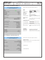
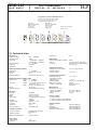
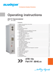
Professional Headend Solutions
Operating instructions
SAT-TV Demodulator
DVB-S/-S2 → CI → ASI-TS & A/V
Contents
1. Safety and operating instructions.................................................................... 2
2. Device variants ................................................................................................. 2
3. General ............................................................................................................. 2
4. Front view .......................................................................................................... 3
5. Functional description....................................................................................... 3
6. Adjustments ..................................................................................................... 3
6.1 Adjustment with the Headend Controller................................................... 3
6.2 Adjustment with the PC/ laptop.................................................................. 3
7. Status LED‘s ..................................................................................................... 4
8. Audio socket ...... ............................................................................................. 4
9. Programming by web server . .......................................................................... 5
9.1 Main menu ................................................................................................. 5
9.2 Software options . ...................................................................................... 6
9.3 Loading the program list ........................................................................... 6
9.4 CA menu .................................................................................................... 7
9.5 Multi-decryption menu................................................................................ 7
9.6 Multi-decryption selection.......................................................................... 8
9.7 Multi-decryption test .................................................................................. 9
9.8 Multi-decryption test information................................................................ 9
9.9 Extended settings . .................................................................................. 10
9.10 Manual settings ..................................................................................... 11
9.11 Factory settings...................................................................................... 11
9.12 Status of the device ............................................................................... 12
9.13 Software overview ................................................................................. 12
10. Manual menu control at the Headend Controller ........................................ 13
11. Trap messages ............................................................................................. 13
12. Block diagram . ........................................................................................... 14
13. Operation modes ......................................................................................... 14
14. Head end bus structure................................................................................ 14
15. Application example ..................................................................................... 15
16. Technical data .............................................................................................. 15
17. Glossary ....................................................................................................... 16
18. Bibliography ................................................................................................. 16
19. Document history ......................................................................................... 16
SDB 907
Part No: 9722.01
SDB
907
Part N : 9722.01
SAT-TV Demodulator
DVB-S/-S2 → CI → ASI-TS & A/V
o
B
LINE
1. Safety and operating instructions
When assembling, starting-up and adjusting the modules, it is necessary to consider the system specific
references in the manual instruction.
The modules may only be installed and started up by authorized technical personnel.
When assembling the modules into the receiving points, the adherence of the EMC regulations is to be secured.
The assembly and wiring have to be done without voltage.
All active modules may only be operated with the Headend Controller HCB x00 or Bus Extender
BEB x00.
The main voltage and the operating voltage of the modules working by DC have to be in complience to the operating
parameters described in the technical data.
With all work the defaults of the DIN EN 50083 have to be considered. Especially the safetyrelevant execution of the
DIN EN 60728-11 [6] is necessary!
2. Device variants
SDB 907
9722.01
DVB-S/-S2 → CI → ASI-TS & A/V
Minimum software requirements for HCB x00:
9650.03:
version 2.34*
9650.04/.05: version 3.18*
9652.01:
version 3.18*
*) Updates: www.blankom.de
3. General
The SAT-TV - Demodulator SDB 907 is a module of the head end system B-LINE, which is conceived as a complete system for
middle sized networks. The SDB 907 demodulates DVB-S/ -S2 signals (8PSK, QPSK) into analogue audio/ video signals. A Common Interface slot enables the use of CA-Modules for the reception of scrambled SAT-signals/programmes. Additionally the processed transport stream with the descrambled services is available on the ASI output.
All the components are programmed via a central control unit and will function independently thereafter. The status of the modules
are displayed via LED’s (see chapter 7 “Status LED‘s“).
2
SDB
907
Part N : 9722.01
o
SAT-TV Demodulator
DVB-S/-S2 → CI → ASI-TS & A/V
B
LINE
4. Front view
SAT-TV input
Operating voltage/
control bus
LED “STANDBY“ (red)
LED “READY“ (green)
LED “ADDR.“ (yellow)
Address selector
ASI-TS output
Video output
Audio output
5. Functional description
The SAT-IF input signal is fed to the DVB-S/ -S2 front end, where the selection of a transponder and its QPSK or 8PSK demodulation
are done. The data stream is routed by a switching matrix either to the Common Interface or directly to the DVB module consisting
of a demultiplexer and a MPEG decoder. An analogue video- and an associated stereo-audio signal are generated within the DVB
module. The video signal is filtered and the audio signal is processed by a DA converter afterwards. The SDB 907 supports the output
of additional services like Teletext, WSS, VPS and optional test lines and the display of subtitle. The analogue signal outputs were fed
by buffer amplifiers (for the pin assigment of the audio socket see chapter 8). The audio outputs are balanced to ground. A respective
CA module with smart card, which is supported by the device, has to be used for descrambling.* Multi service decryption is possible
if there are not any restrictions by the CAM itself or by the service provider. The decryption of MPEG-4 services is supported. With this
module its possible to choose elementary streams of a service for decryption. So the ressources of the respective CAM/ smart card
combination can be used optimally. BISS decryption can be performed by activating the software option CKB 104. Supported are the
BISS mode 1 and the BISS mode E with entering the necessary Injected ID, but not the BISS mode E with the optional Buried ID. The
activation of the software option CKB 105 allows the output of the processed data stream on the ASI-TS connector. The multi service
decryption is enabled therby.
*
The design of the Common interface of this module is done according to DVB standards. Because of the dependencies in interaction of the DVB signals, CA modules and smart cards we can not assure a general functional capability for all application possibilities. Please contact our service
department for further assistance.
6. Adjustments
6.1 Adjustment with the Headend Controller
·Adjustment of the addresses at the Bus Extender BEB x00 and at the modules
·Activation of the programming mode on each module by selecting the line (BEB x00) and the module position (1... 15) at the
Headend Controller(HCB x00)
→ yellow LED illuminates until the beginning of the parameter adjustment
·Adjustment of the SDB 907 parameters (see chapter 10) → green LED is switched on
·After the programming the SDB 907 will be automatically switched into the operating mode
→ yellow LED flashes shortly/ green LED is switched on
6.2 Adjustment with the PC/ laptop
·Prerequisite for the remote programming is an “online connection” according the IP standard and an ethernet connection at the PC/ laptop
·Adjustment of the line/ position addresses at the Bus Extender BEB x00 as well as at the modules
·At the Headend Controller HCB x00 input IP address (default: 192.168.2.80)
·For “direct connection” between a PC and HCB x00 use crossover cable (RJ 45)
·For connection over a HUB use a normal straight throught patch cable
·Start-up HTML browser and put in IP address as target address
·If connected correctly the web interface will be opened on the pc and a blue LED (LINK) at the HCB x00 will be lit up.
·All adjustments of the modules are specified on the web interface.
The manual instructions of the Headend Controller HCB x00 and the Bus Extender BEB x00 have to be considered!
3
SDB
907
Part N : 9722.01
SAT-TV Demodulator
DVB-S/-S2 → CI → ASI-TS & A/V
o
7. Front panel LED`s
Designation (Colour)) Status
Meaning of display
STANDBY (red)
permanently on
module is in standby
flashing
module faulty (hardware error)
permanently on
module working properly
flashing
error warnings, depending on signal:
- tuner not synchronized (e.g. there is no input signal)
- service settings are not valid
illuminated/ flashing
remote control connection/ data being exchanged
READY (green)
ADDR. (yellow)
8. Audio socket
Pin assignment
5
3
8
2
4
7
1
1
2
3
4
5
6
7
8
stereo left+/ dual A+/ mono+
screening/ earth
stereo right+/ dual B+
stereo left-/ dual A-/ monostereo right-/ dual Bcontrol line contact 1
control line contact 2
control line return path (earth)
6
Audio mode
Mono
Pins 6/ 8: Connection open
Pins 7/ 8: Connection closed
Stereo
Pins 6/ 8: Connection closed
Pins 7/ 8: Connection open
Dual
Pins 6/ 8: Connection closed
Pins 7/ 8: Connection closed
or
Pins 6/ 8: Connection open
Pins 7/ 8: Connection open
4
B
LINE
SDB
907
Part N : 9722.01
o
SAT-TV Demodulator
DVB-S/-S2 → CI → ASI-TS & A/V
B
LINE
9. Programming by web server*
9.1 Main menu
Name of device, item number, address in head end
Description Name of program (max. 30 characters)
Input
SAT-IF
Symbol rate
Standard
FEC (DVB-S stand.)
Roll-Off (DVB-S2 st.)
Status adjustment range: 950 ... 2150 MHz
adjustment range: 1000 ... 45000 kSps
selection: DVB-S, DVB-S2
selection: 1/2, 2/3, 3/4, 5/6, 7/8, auto
selection: 20, 25, 35 %
display whether SYNChronization or
noSYNChronization with input
BISS-Settings
(will only be available if “BISS decryption” option is on)
BISS-Key
BISS-E injected-ID input of the 12-digit code in BISS mode 1
or the 16-digit code in BISS mode E
input of the 14-digit code in BISS mode E,
no input in BISS mode 1!
ASI-Output
Polarity
TS-Source
selection: normal, inverse
selection: auto, original
A/V-Program settings
Program listing see menu 2
Service ID adjustment range: 0...65535
Audio language adjustment range: 0...47
Language code displays the code of the selected language
Service type displays the type of selected service
(TV, Radio)
Audio settings
Audio gain adjustment range: +6...-20 dB
Common Interface
Status
CA-Menu
status message of the CA module
see menu 3
Multidecryption
Menu
see menu 4
Operating status SNMP-Trap mess. SYNC-Control Factory settings selection: On, Off, Reset
On/Off, if SNMP option in HCB x00 is
enabled,otherwise “locked“ is displayed
synchronization test at input. selection:
fast, normally, slowly
see menu 10
Routing to the appropriate adjustment menu:
Software option see menu 1
Extended settings see menu 8
Status see menu 11
Software overview see menu 12
* For further details see the HCB manual
5
SDB
907
Part N : 9722.01
o
SAT-TV Demodulator
DVB-S/-S2 → CI → ASI-TS & A/V
B
LINE
9.2 Software options (menu 1)
Name of device, item number, address in head end
Dialogue for entering a code to activate the “test line”
(CKB 101), “subtitling” (CKB 102), “BISS decryption”
(CKB 104) and ”ASI output“ (CKB 105) software options . When
the page is called, the current state of activation will be displayed.
9.3 Loading the program list (menu 2)
This menu contains a list of all MPEG-2 services available in the data stream. Audio- and DVB subtilte language selection can take
place here if there are any available. A service is adopted or changed by clicking the relevant “Set” button.
6
SDB
907
Part N : 9722.01
o
SAT-TV Demodulator
DVB-S/-S2 → CI → ASI-TS & A/V
B
LINE
9.4 CA menu (menu 3)
Name of device, item number, address in head end
On these pages all menus implemented in the CA module are
offered.The available menus are selected individually or are
invoked one-by-one to do necessary settings or to get all informations about the CA module.
9.5 Multi-decryption menu (menu 4)
When calling this menu the selection of the services of the adjusted transponder, which were selected for decryption and whose decryption was successfully, appears. Indicated are the program name with the number of the decoded PID‘s, the decryption settings
and the status of the program. “Stored“ means, that the service was successfull decrypted and saved in the CA-service-list. Using the
check box “Clear entries“ and the ”Transmit / Back“ button the entire selection will be deleted and no services are decrypted afterwards. By using the “Selection“ button and the appropriate selection of the services in the multi-decryption selection menu (menu 5)
the list of the services to decrypt can be changed.
Using the “Testing selection“ button calls the test menu (menu 6), in which the decryption state of all programs in the CA-service-list
will be tested again and possible occurring errors will be listed.
7
SDB
907
Part N : 9722.01
o
SAT-TV Demodulator
DVB-S/-S2 → CI → ASI-TS & A/V
B
LINE
9.6 Multi-decryption selection (menu 5)
In this menu all services of the adjusted transponder and their CA status are listed. The services are selectable for decryption. For
each of this selected services one can determine, what streams or PID‘s are to be decrypted. That‘s important because the maximum
number of the decryptable PID‘s is limited and this limit has a different size per CA module.
In the selection boxes “MPEG 1/ 2 Audio Streams“ respective “Subtitling Streams“ all, no or individual streams are selectable. If one
wants to select more than one stream, but not all, the selection field ”all“ in the box is to be selected and in the column “PID-Drop list“
all PID‘s have to be entered, that shall not be decrypted.*
In the column “PID-Drop list“ all PID‘s are listed, that shall not be decrypted. The PID‘s can be given in decimal or hexadecimal format
and have to be separated by a semicolon. The maximum number of PID‘s is 10.**
Individual CA modules have to be initialized once again before the CA services will be sent to the module. To do so the option “Reset
CA-Modul“ can be activated.
“Other Audio Streams“ includes all AC3-, DTS- and AAC-Streams. “Private Streams“ selects all streams which are not captured by the other selection
fields.
**
Particularly PID‘s can be given here, which are active only at times and no authorisation for decryption is available for them.
*
8
SDB
907
Part N : 9722.01
o
SAT-TV Demodulator
DVB-S/-S2 → CI → ASI-TS & A/V
B
LINE
9.7 Multi-decryption test (menu 6)
First all services, which are saved in the CA-service-list, will be tested for the current decryption status.
After the end of the test the multi-decryption menu (menu 4) appears, where in the “Status“-column the test result of the respective
service is stated by using the “Info“ button, the relevant information page of the test (menu 7) is displayed.
By clicking of the “Transmit / Back“ button all settings are transmitted. The “Selection“ button routes back to menu 5 to correct input
values, e.g. too much PID‘s were selected.
9.8 Multi-decryption test information (menu 7)
Name of device, item number, address in head end
On this page informations about the test result of the selected
service are displayed. First the final result of the test with service
ID and CA information is listed, than for each requested PID the
type, the CA information and the test result.
9
SDB
907
Part N : 9722.01
o
SAT-TV Demodulator
DVB-S/-S2 → CI → ASI-TS & A/V
B
LINE
9.9 Extended settings (menu 8)
Name of device, item number, address in head end
Video Video output
Color bar Color system Video format settings of the video parameters
selection: On, auto Off, auto colour
palette bar
selection: On, Off
selection: PAL, SECAM, NTSC
selection: Letterbox,center cut,1:1,
pillarbox, 4:3 vertical cut, 20:9 letterbox
VPS-Settings
CNI-Code Source audiomode Source PIL adjustment range: 0x000…0xFFF hex.
selection: MPEG, A056(MPEG)
selection: A056(PDC), A056, PDC,
TimerControlCode
Complementary data
Teletext
selection: On, Off
WSS-Insertion selection: On, Off
SDT/ PMT-Processingselection: On, Off
Mode CA-PMT-
selection: CA-PMT-List, CA-PMT-Entry
Update
(isn‘t supported by all CAM‘s)
Subtitling
(will only be available if “Subtitling” option is on)
Mode selection: Off, Teletext, DVB
Settings DVB-Subtitling
(will only be available if “Subtitling” option is on)
DVB-Languages index adjustment range: 0...16
DVB-Language code displays the code of the language
selected
Use extended ID‘s
selection: yes, no
Composition Page ID displays the ID (decimal number)
Ancillary Page ID displays the ID (decimal number)
Settings Teletext-Subtitling
(will only be available if “Subtitling” option is on)
Teletext page
Background Character mode adjustment range: 0...899
selection: not transparent, semi-transparent, transparent, black transparent
selection: auto, manual
The following settings are only used in manual character mode.
Basic character Supplementary character
National table Test line
selection: Latin,Cyrillic-1,Cyrillic-2, Cyril-
lic-3, Arabic, Greek, Hebrew
selection: Latin, Cyrillic, Arabic, Greek,
Hebrew
selection: standard table, alternative
table, no country code, English, German,
Swedish, Italian, French,Spanish, Czech,
Rumanian, Polish, Estonian, Latvian,
Serbian, Turkish, Danish
(will only be available if “Test lines” option is on)
Line 17 Line 18
Line 330
Line 331
a test signal can be sent on all four of
these lines,the signal selection is:
off, CCIR17, CCIR 18, CCIR 330m,
CCIR331, Sinus (x)/x, Ramp
Routing to the appropriate adjustment menu:
Manual settings see menu 9
10
SDB
907
Part N : 9722.01
o
SAT-TV Demodulator
DVB-S/-S2 → CI → ASI-TS & A/V
B
LINE
9.10 Manual settings (menu 9)
Name of device, item number, address in head end
PCR for current service
Use PCR PID adjustment range: 0..8190
Manual PID-Settings
PCR-PID adjustment range: 0..8190
Video-PID adjustment range: 0..8190
Audio-PID adjustment range: 0..8190
Teletext-PID adjustment range: 0..8190
VBI-PID adjustment range: 0..8190
Subtitle-PID adjustment range: 0..8190
Composition Page-ID adjustment range: 0..65535
Ancillary Page-ID adjustment range: 0..65535
9.11 Factory settings (menu 10)
When this menu item is requested, at first a security query
whether it really set all parameters to the factory default settings pops up.
Affirming the query, all settings stored in the EEPROM will be
deleted and replaced by the default settings. The module will
go back to these default values. Once the setting process is
over, there will be an automatic return to the main menu.
11
SDB
907
Part N : 9722.01
o
SAT-TV Demodulator
DVB-S/-S2 → CI → ASI-TS & A/V
B
LINE
9.12 Status of the device (menu 11)
Name of device, item number, address in head end
Tuner
Status Input frequency
offset
Input power
Noise margin
BER/ PER
DVB-S2-Parameter
displays whether SYNChronization or
noSYNChronization
displays the frequency deviation from
requested input frequency
in dBµV
in dB
bit error rate (DVB-S)/
packet error rate (DVB-S2)
according to the signalling DVB-S2 infor-
mation
MPEG-Decoder
Status Synchronization status for the TS audio and video decoder
Complementary data
Current VPS-Data displays detailed information about
current VPS data
Current WSS-Data displays detailed information about
current WSS data
The following will only be displayed if the “test lines” option is switched
on:
Test line insertion displays which test signal is set for the 4
lines
Information
Temperature Device number Device index temperature of terminals board
display of the device number
display of the device index (hardware)
9.13 Software overview (menu 12)
Name of device, item number, address in head end
Software versions
Displays the software versions for the controllers as follows:
- Controller of terminals board
- MPEG-Decoder
- FPGA-ASI-Encoder
12
SDB
907
Part N : 9722.01
SAT-TV Demodulator
DVB-S/-S2 → CI → ASI-TS & A/V
o
10. Manual menu control at the Headend Controller (HCB x00)
SDB 907 start
Edit or Close
Power status
On/ Off
SAT IF input
Frequency
Symbol rate Standard
FEC (DVB-S)
Roll-off (DVB-S2)
950 ... 2150 MHz
1000 ... 45000 kSps
DVB-S, DVB-S2
auto, 1/2, 2/3, 3/4, 5/6, 7/8
20, 25, 35 %
Scan
No
Service ID
Audio-Index
0 .. 65535
0 .. 47
Yes
Program selection
Language selection
ASI settings
ASI polarity
ASI-TS source
normal, inverse
auto, original
TV sound
Audio gain
+6 ... -20 dB
Video settings
Video output
Colour system
Colour bar
Video format
On, auto off, auto colour palette bar
PAL, SECAM, NTSC
On/ Off
Letterbox, center cut, 1:1, pillarbox,
4:3 vertical cut, 20:9 Letterbox
VPS settings
VPS-CNI-Code
Source VPS Audio
Source VPS-PIL
0x000 ... 0xFFF
MPEG, A056(MPEG)
A056(PDC), A056, PDC,
Timer Control Code,
Additional data
SDT/ PMT processing
On/ Off
Teletext
On/ Off
WSS insertion
On/ Off
Teletext page
0 .. 899
not transparent, semi-transparent,
Background
transparent, black transparent
Channel name
SDB 907 end
11. Trap messages
Item
Message
Message type
Explanation
01
Signal OK
INFORMATION
Component working, everything ok
02
Input not sync
WARNING
Input not synchronized
03
MPEG Error
CRITICAL
MPEG error
04
System reset
WARNING
System has been reset after internal error
05
MPEG-Decoder not sync
WARNING
MPEG decoder not synchronized
06
Power fail
CRITICAL
Power supply error
07
Decoding of service ... fail
WARNING
Error on descrambling of service...
08
Decoding of service ... ok
INFORMATION
Descrambling of service ... ok
13
B
LINE
SDB
907
Part N : 9722.01
B
SAT-TV Demodulator
DVB-S/-S2 → CI → ASI-TS & A/V
o
LINE
12. Block diagram
Video
CVBS
MPEG decoder
TS
SAT IF
950...
2150 MHz
DVB-S/ -S2
front end
V
BISS
descrambler
TS
Video- /
Audioprocessing
A
K1/ K2control
CI
TS
selector
Power supply
&
control
DVB table
processing
ASI
ASI
CAM
13. Operation modes
Operation mode
BISS
CAM
ASI-Out
FE-TS
MPEG-2 DVB services
x
CAM-TS*
x
x
x
x
x
x
*
x
Remark
service ID set
manual PID‘s = 0
x
x
x
manual PID selection
A/V-Out
(MPEG 2)
x
x
MPEG-4 services
Audio
analogue
service ID = 0
manual PID‘s = 0
x
x
x
manual PID‘s set
CAM-TS: automatic changeover between FE- und CAM-TS
Module
ADDR. 15
Module
ADDR. 15
Module
ADDR. 15
Module
ADDR. 01
Module
ADDR. 01
BEB x00
ADDR. 01
Module
ADDR. 01
Module
signal processing
unit
.
BEB x00
ADDR. 02
BEB x00
Bus Extender
BEB x00
ADDR. 15
HCB x00
Headend
Controller
HCB x00
14. Head end bus structure
The number of the possible module connections (00 ... 15) to a
BEB x00 depends on the total power consumption of this line!
14
SDB
907
Part N : 9722.01
B
SAT-TV Demodulator
DVB-S/-S2 → CI → ASI-TS & A/V
o
LINE
15. Application example
Integration in existing B-LINE structure
Conversion of 2 SAT transponders into 2x QAM
+ 2 services of the same transponder into PAL
included the multidecryption option
SAT IF Input
Input level min.:42 dBµV
0.95...2.15 GHz
SAT IF Input
Input level min.:42 dBµV
0.95...2.15 GHz
i.e.: Astra 19,2°
High Horizontal
i.e.: Astra 19,2°
High Vertikal
output to existing combiner
2xQAM + 2xPAL
A/V
DVB-S/S2
ASI
ASI
DVB
SDB907
ASI
ASI
A/V
HCB100
A/V
DVB-S/S2
DVB
A/V
AMB406
VMB191
SDB907
AMB406
PCB190
VMB191
16. Technical data
SAT IF input
Frequency range Frequency step AFC range AGC level range Connector Impedance DVB-S demodulator (QPSK)
Symbol rate Code rate Roll-off Signal processing Impedance
950 … 2150 MHz
1 MHz
± 3 MHz (SR < 10 MSps)
± 5 MHz (SR ≥ 10 MSps)
42 … 82 dBμV
F socket
75 Ω
1 … 45 MSps
1/2, 2/3, 3/4, 5/6, 7/8
35 %
EN 300 421 (DVB - S) [1]
DVB-S2 demodulator (QPSK, 8PSK)
Symbol rate QPSK 5 … 36 MSps
8PSK
5 ... 30 MSps
Code rate QPSK 1/4, 1/3, 2/5, 1/2, 3/5, 2/3, 3/4, 4/5, 5/6, 8/9, 9/10
8PSK
3/5, 2/3, 3/4, 5/6, 8/9, 9/10
Roll-off 20, 25, 35 %
Signal processing EN 302 307 (DVB - S2) [2]
ASI output
Data rate Polarity Mode
TS data rate
TS mode
Output voltage
Connector Impedance Signal processing 270 Mbps
normal/ inverted
burst, continuous
according symbol rate and
coding
188 Bytes
800 mVpp ± 10 %
BNC socket
75 Ω
EN 50083-9 [3]
Decryption interface
Common Interface
Operating voltage
Multi-Service Decryption
PCMCIA-Slot according
EN 50221 [4]
5V
21 services max.
Video output
Output voltage
Connector
1 Vpp
BNC socket
Audio output
Rated level (at digital -6 dBFS)
Output
Connector
Operating parameters
Voltage/ current (w/o CAM)
Residual ripple of
supply voltage
Environmental conditions
Temperature range Temperature range for
data keeping Relative humidity Method of mounting Location of mounting Miscellaneous
Dimensions (l x w x h)
without 19”-adapter with 19”-adapter Weight 75 Ω
Antennenanlage
6 dBu
Betreiber
Bearbeitet von
Datum
symmetrical, free-of-ground
Heinze
Größe
Datei
Blatt
DIN A4 Beispiel_SDB907eng.net
1 von 1
socket according
DIN 45326[5]
IEC 130-9-20
Version
AND Version 4.0, Serien-Nr. 1581 für:
Blankom Antennentechnik GmbH Hermann-Petersilge-Str. 1 07422 Bad Blankenburg
12 V (± 0.2 V)/ 500 mA
≤ 10 mVpp
-10 ... +55 °C
5 ... 45 °C
≤ 80 % (non condensing)
vertical
splash-proof and
drip-proof
50 x 276 x 148 mm
50 x 301 x 148 mm
1,300 g
Delivery content
1 x Bus connector
1 x Audio connecting cable ASK 525
1 x Video connecting cable VVK 526
Software options
Test line Subtitling BISS decryption Activation of ASI output
15
CKB 101 (9650.51)
CKB 102 (9650.52)
CKB 104 (9650.54)
CKB 105 (9650.55)
08.06.2009
Blattname
SDB
907
Part N : 9722.01
B
SAT-TV Demodulator
DVB-S/-S2 → CI → ASI-TS & A/V
o
LINE
17. Glossary
AP ASI AV BISS
CA
CAM
CI
CCIR DVB FPGA HTML
HTTP ID IIC IP LED MC MIB MPEG NTSC
PAL
PCR PDC
PID
PMT PLL
SECAM
SNMP SPI SPTS TS TV VPS WSS Anschlussplatte (Terminals board)
Asynchronous Serial Interface
Audio/Video
Basic Interoperable Scrambling System
Conditional Access
Conditional Access Module
Common Interface
Comité Consultatif International des Radiocommunications
Digital Video Broadcasting (-C Cable, -S Satellite, -S2 Satellite 2, -T Terrestrial)
Field Programmable Gate Array
Hypertext Markup Language
Hypertext Transfer Protocol
Identifier
Inter-Integrated Circuit (I²C-Bus, data bus within device)
Internet Protocol
Light Emitting Diode
Microcontroller
Management Information Base
Moving Picture Experts Group
National Television Systems Committee*
Phase Alternating Line*
Programme Clock Reference
Programme Delivery Control, synonym of VPS
Packet Identifier
Programme Map Table
Phase-locked loop,
Séquentiel couleur à mémoire*
Simple Network Management Protocol
Serial Peripheral Interface
Single Programme Transport Stream
Transport Stream
Television
Video Programming System
Wide Screen Signalling
*
colour-encoding systems of analogue television
18. Bibliography
[1] EN 300 421: Digital Video Broadcasting (DVB): Framing structure, channel coding and modulation for 11/12 GHz satellite
services
[2]EN 302 307: Digital Video Broadcasting (DVB): Second generation framing structure, channel coding and modulation systems for Broadcasting, Interactive Services, News Gathering and other broadband satellite applications
[3]EN 50083-9: Cabled distribution systems for television, sound and interactive multimedia signals, part 9: Interfaces
for CATV/SMATV head ends and similar professional equipment for DVB/MPEG-2 transport streams
[4]EN 50221: Common interface specification for conditional access and other digital video broadcasting decoder applicati
ons; German version EN 50221:1997 + Corrigendum:2000
[5]DIN 45326 / EN 60130-9: Connectors for frequencies below 3 MHz - Part 9: Circular connectors for radio and associated sound equipment, 2000-05
[6]EN 60728-11: Cable networks for television signals, sound signals and interactive services Part 11: Safety
(IEC 60728-11:2005); German version EN 60728-11:2005
[7]RFC 1157 Request for Comments (RFC): RFC Database URL: http://www.rfc-editor.org/rfc.html
19. Document history
Version
Date
Modification
Author
1.00
05.06.2009
basic document
Häußer
1.01
23.03.2001
revision (chapter 9.9)
Häußer
Options and other TV standards available upon request. Subjects to changes due to technical progress.
BLANKOM Antennentechnik GmbH
Hermann-Petersilge-Straße 1 • 07422 Bad Blankenburg • Germany • Telefon +49 (0) 3 67 41 / 60-0 • Fax +49 (0) 3 67 41 / 60-100
16
Declaration of Conformity
The Manufacturer
BLANKOM Antennentechnik GmbH ∙ Hermann-Petersilge-Str. 1 ∙ 07422 Bad Blankenburg ∙ Germany
herewith declares the conformity of the product
Product name:
SAT-TV Demodulator
Type:
SDB 907
Product number:
9722.01
according to the following regulations
EN 50083-2
EN 60728-11 (as far as relevant)
and additional device-specific regulations, enclosed above, which this product is subjected to.
Date: 04.06.2009
Signature:
(Managing Director)
17