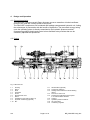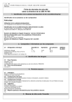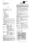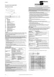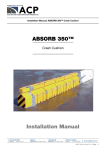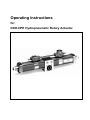
1
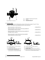
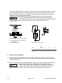
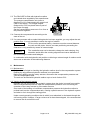
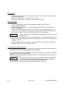
Operating Instructions for DSO-HPE Hydropneumatic Rotary Actuator Contents 1. 2. 3. 4. 5. 6. 7. 8. Specifications Safety General Design and operation Mounting and Installation Maintenance Trouble shooting Spare parts 1. Page Page Page Page Page Page Page Page 2 3 4 5 7 8 10 10 Specifications Operating pressure Compressed air Compensating pressure Operating temperature 2 bar to 10 bar filtered, lubricated or not lubricated 2 bar to 4 bar 15 °C to 80 °C Hydraulic medium For hydropneumatic rotary actuators slide oils of the viscosity class ISO VG 32 (32 mm²/s at 40°C) are recommended. The manufacturer supplies the actuators filled with hydraulic medium Mobil Vactra No. 1. This hydraulic medium is available at SPECKEN DRUMAG. Intended use DSO-HPE Hydropneumatic Rotary Actuators are driving elements which serve to perform rotary motion in alternating direction and within a limited angle of rotation depending on the piston stroke. Employment of the unit for any other purpose shall not be deemed the intended use. The manufacturers will not assume any liability for damage resulting from any other use than the intended use. 901 Page 2 of 10 BE_DSOHPE korrig.doc 2. Safety Safety symbol Caution ! This Caution ! symbol is included in the Operating Instructions wherever special care must be exercised. Operational safety The DSO-HPE Hydropneumatic Rotary Actuator is designed and manufactured according to the state of the art, and is operationally safe when properly installed. The operational safety of the overall system is subject to the assessment of the manufacturer of the overall system. Any person involved with the installation of the DSO-HPE must have read and understood the Operation Instructions and, in particular, these safety instructions. The manufacturers will not assume any liability for arbitrary alterations and modifications to the unit. DSO-HPE Hydropneumatic Rotary Actuators are driving elements which serve to perform rotary motion in alternating direction and within a limited angle of rotation depending on the piston stroke. Employment of the unit for any other purpose shall not be deemed the intended use. The manufacturers will not assume any liability for damage resulting from any other use than the intended. For any rotary motion, whether through applying pressure to the pistons or turning the pinion from outside, under the condition of pressure compensation connected, the compensation tank must be filled with hydraulic pressure medium ensuring a pneumatic pressure between 2 bar and a maximum of 4 bar. The camshaft centrelines must not be altered to change the tooth clearance. Special care must be exercised with regard to the pinion shaft/machine connection due to oscillations of the pinion occurring during operation. For DSO-HPE Rotary Actuators with a function "6" control unit (stop at any position), switching off of the control signal may cause high pressure peaks depending on the moment of inertia and speed. It is recommended to have the manufacturer checked the design, if appropriate. Any increase in the moments of inertia and/or speeds used as the basis for designing the unit, may cause damage. 901 Page 3 of 10 BE_DSOHPE korrig.doc 3. General Basic information The EU machine directive 2006/42/EC does not apply to this device. Therefore, it is also not provided with the CE marking according to the machine guideline. These operating instructions are intended to enable the manufacturer of the overall operational system to properly install the device and instruct the user about any necessary maintenance. These operating instructions are intended for engineers of the manufacturer providing the overall system, and not for the user of the system. It is assumed that the fundamentals of pneumatics and hydraulics are known. Only if these operating instructions are understood and complied with can installation mistakes can be avoided and trouble-free operation be guaranteed. However, if you do encounter problems please contact our company, field staff or agencies. We reserve the right to make technical modifications Copyright The copyright of these Operating Instructions shall remain with SPECKEN-DRUMAG. SPECKEN AG Im Lörler 6 CH-8902 Urdorf Phone: 0041 (0)1 7340366 Fax: 0041 (0)1 7342313 DRUMAG GmbH Postfach 1142 D-79702 Bad Säckingen Phone: 0049 (0)7761 5505-0 Fax: 0049 (0)7761 5505-70 901 Page 4 of 10 BE_DSOHPE korrig.doc 4. Design and Operation 4.1 General description The DSO-HPE Hydropneumatic Rotary Actuator serves to transform a limited rectilinear motion of the rack into a rotary motion of the pinion. The DSO-HPE comprises a self-contained and leakage-compensated hydraulic unit, linking the advantages of pneumatics with the benefit of hydraulics. The pneumatic energy acting upon the operating piston is directly transmitted to the hydraulic pressure medium. Integrated regulating throttle and control valves facilitate rotary motions that can be sensitively adjusted and positioned. 4.2 Design Fig. 1 DSO-HPE 22 1.1 1.2 1.3 1.4 1.5 1.6 1.7 1.8 1.9 1.10 901 Housing Pinion Rack Camshaft Screw Standard end cover Piston Ventilation screw (refer to item 6.2) Hydraulic cushioning (optional) Nut 1.11 1.12 1.13 1.14 1.15 1.16 1.17 1.18 1.19 Page 5 of 10 Stroke limiter (optional) Control pin (optional) Sealing and counternut for stroke-limiting device Function 2 control unit Knurled nut to adjust the pinion speed in counterclockwise direction Locknut Hydraulic pressure medium Air connections Cushioning regulator BE_DSOHPE korrig.doc 2.1 2.2 2.3 2.4 Fig. 2 Function 6 control unit Knurled nut to adjust the pinion speed Locknut Releasable check valve Control air connection 4.3 Function modes The hydraulic flow can be influenced by means of the function modes "2" and "6". Four possible combinations are provided by the two control elements. - Speed adjustable in both directions = DSO-HPE 22 - Speed adjustable in both directions and stop possible for counterclockwise motion of pinion = DSO-HPE 62 - Speed adjustable in both directions and stop possible for clockwise motion of pinion = DSO-HPE 26 - Speed adjustable in both directions and stop possible for both directions of pinion motion = DSO-HPE 66 Fig. 3 Example diagram for function mode 22 Fig. 4 Example diagram for function mode 62 3.1 Compensation system 3.01 Function mode 2 control unit to adjust the pinion speed for clockwise motion 3.02 Function mode 2 control unit to adjust the pinion speed for counterclockwise motion 4.1 Compensation system 4.01 Function mode 2 to adjust the pinion speed for clockwise motion 4.02 Control unit 6 to adjust the pinion speed and stop pinion motion for counterclockwise direction 4.4 Pneumatic pressure compensation 901 Page 6 of 10 BE_DSOHPE korrig.doc Pressure compensation is an important element of self-contained hydropneumatic systems. The compensation system to be filled with Mobil Vactra No. 1 or an identical slide oil to a level of about 70%, serves to compensate for hydraulic medium differences in the rotary actuator, caused by temperature changes. In addition the reserve oil volume serves to compensate for losses at sealing points. During operation and also when turning the pinion from outside, a Caution ! pneumatic pressure of 2 to 4 bar must be ensured for the compensation system. For high angular velocities an upper range compensation pressure is recommended. Fig. 5 Diagram of pressure compensation 5.1 Pressure regulator (low-pressure) 5.2 Manometer 5.3 Compensation tank Fig. 6 Compensation system Type X02-38399 X01-29472 5. Oil volume cm³ A B C D 125 500 78 122 180 291 39 70 95 125 Mounting and Installation 5.1 The DSO-HPE Rotary Actuator can be screw-mounted to the machine system on three sides of its housing (bottom, front and rear sides). The machine system’s mounting surface must be machined. 5.2 Due to oscillations occurring during operation, special care must be exercised with regard to the connection between the rotary actuator pinion shaft and the machine shaft. When using a feather key connection for transmitting moments a fit Caution ! without clearance is required. Otherwise braking and acceleration torques in the end positions may cause deflection of the feather key connection. 901 Page 7 of 10 BE_DSOHPE korrig.doc 5.3 The DSO-HPE is filled with hydraulic medium and vented when supplied by the manufacturer. The pressure compensation unit (refer to diagram Fig. 5) is connected to the control unit (refer to the figure). The straight adapter designed for a 5/3 mm plastic hose is part of the scope of supply. Set the compensation pressure to 2 to 4 bar at the pressure regulator. 5.4 Connect the compressed air according to the state of the art. 5.5 If a rotary actuator with a stroke-limiting device has been supplied, you may adjust the end position then. It is only possible to reduce the angle of rotation. For the unit’s operational safety, clearance must be ensured between Caution ! the rack and the pinion. Hence, accurate positioning exceeding the clearance is only possible by means of external stops. The camshafts must not be altered to change the tooth clearing. Any alteration would affect the centring alignment and cause deflection of the rack during the stroke and leakages. Caution ! In combination with the hydraulic end position cushioning a reduced angle of rotation would also mean a reduction of the cushioning distance. 6. Maintenance 6.1 Maintenance Maintenance is limited to checking the hydraulic medium level in the compensation system. Refilling by using different hydraulic mediums is not permitted. Before any refilling, stop the rotary actuator, disconnect the compensation pressure and vent the compensation tank. The tank can be filled with hydraulic medium up to a level of about 70%. 6.2 Venting of the hydraulic system Normally, air can only access the hydraulic system when the pinion is turned from outside without compensation pressure, when the compensation pressure is too low during the operation of the rotary actuator or if the seals are worn. As a result of the lacking or insufficient compensation pressure the hydraulic medium is pushed back into the compensation tank, causing a partial vacuum in the hydraulic system and take-in of air through the sealing points. Under normal operating conditions the air which is not absorbed, is eliminated through the self-venting effect. However, if larger volumes of air have been trapped, it is recommended to remove the oil and refill the unit. 901 Page 8 of 10 BE_DSOHPE korrig.doc Requirements - The rotary actuator has to be in a horizontal position, venting screws (Pos. 1.8) upside, control units downside. Both air connections (Pos. 1.18) have to be relieved. Speed regulations (Pos. 1.15) fully opened for maximum speed Filling and venting - Connect compensation tank to the compensation adapter (see 5.3) and fill compensation tank with oil Remove venting screws (Pos. 1.8), insert adapters with plastic hose into threads to collect discharging oil. Set compensation pressure to 0.5 to 1 bar , until air-free oil discharges the hose. To allow the air to vent through the venting screw lift the rotary actuator alternating on the left and the right side. Then relieve compensation tank from air pressure. Make sure that the compensation tank is refilled continuously during the filling process. After relieving air pressure from the compensation tank no oil should discharge from the rotary actuator. Discharging oil is a sign of remaining air in the oil. If so, then repeat the venting procedure. Caution ! - - Remove adapters and hoses and plug venting threads. The tank should be filled with hydraulic medium up to a level of about 70%. 6.3 Replacing of gaskets and seals The quality of motion, efficiency and maintenance intervals are decisively influenced by the combination of pressure medium/seal/piping microgeometry. When the specified hydraulic medium is used and the compressed air is filtered, it is hardly necessary to replace any gasket or seal. However, when a replacement becomes necessary, it is recommended to have this done by the manufacturer. Only replace the piston seals when performing replacement operations Caution ! on the spot. Any opening of piston fastening nuts would destroy the settings, causing poor motion behaviour, higher leakage and higher wear. Always check the condition of the sliding faces and replace worn parts. 901 Page 9 of 10 BE_DSOHPE korrig.doc 7. Trouble shooting Fault Cause Remedy - Excessive medium losses at the compensation tank - Hydraulic gasket leaks - Refer to Section 6.3 - Nonuniform motion behaviour - Air in the hydraulic system - Refer to Section 6.2 - End position is not approached accurately - Feather key connection deflected - Refer to Section 5.2. or choose friction-tight connection - Rack worn - Contact manufacturer - Overpressure in the oil chamber, e.g. through temperature change - Loosen ventilation screw (Fig. 1, Section 1.8) to relieve pressure. - With control function 6 the rotary actuator does not start from its end position after a longer shut down period. 8. Spare parts When ordering spare parts please indicate the model designation and part number of the desired unit. Seals and gaskets are available in complete sets only. -------------------- 901 Page 10 of 10 BE_DSOHPE korrig.doc