1
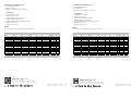
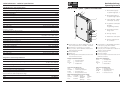
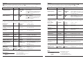
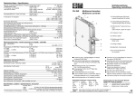
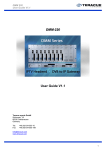
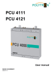
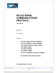
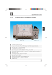
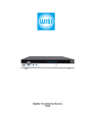
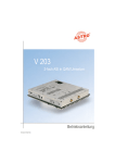
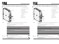
Operating instructions OV 75C DVB / QPSK - QAM Transmodulator with ASI interface Operating instructions OV 75C DVB / QPSK - QAM Transmodulator with ASI interface 1. Looped-through input (F) 1 1. Looped-through input (F) 1 2 2 2. Looped-through output (F) 3 2. Looped-through output (F) 3 4 4 3. ASI IN (BNC) 3. ASI IN (BNC) 5 5 4. ASI OUT (BNC) 4. ASI OUT (BNC) 5. SAT IF Input (F socket) 5. SAT IF Input (F socket) 6. Programming interface Mini DIN 6. Programming interface Mini DIN 7. Fixing screw 7. Fixing screw 8. Display 6 8. Display 6 9. Control panel 9. Control panel 10.DC connector 7 10 Note: 8 9 10 Specifications, features and operations are identical with OV 75 (043 437) excepting: ASI-IN* OFF/ON. OFF= QPSK demodulator is internally directly connected to the QAM modulator Specifications - ASI, output Transmission format Impedance Datarate depending of input symbol rate (2-45 MS/s) Specifications - ASI, input Receive format Impedance ASI input data rate (ASIRATE*) Paket length (PLENGTH*) * shown in display ASI = Asynchronous Serial Interface 10.DC connector 7 8 Note: Specifications - ASI, input Receive format Impedance ASI input data rate (ASIRATE*) Paket length (PLENGTH*) * shown in display Burst 188 Byte / Burst 204 Byte / Paket 204 Byte 75 Ω 10-53,95 MBit/s 188 / 204 OC/1-OT-595 Setting the modul number (refer to mounting instructions "OV 51Headend controller" 042 246) Specifications, features and operations are identical with OV 75 (043 437) excepting: ASI-IN* OFF/ON. OFF= QPSK demodulator is internally directly connected to the QAM modulator Specifications - ASI, output Transmission format Impedance Datarate depending of input symbol rate (2-45 MS/s) Burst 204 Byte 75 Ω Processing of symbol rates 2-45 MS/s. Controlling and monitoring via PC and RS 485 interface 9 ASI = Asynchronous Serial Interface Burst 204 Byte 75 Ω Burst 188 Byte / Burst 204 Byte / Paket 204 Byte 75 Ω 10-53,95 MBit/s 188 / 204 Processing of symbol rates 2-45 MS/s. Controlling and monitoring via PC and RS 485 interface OC/1-OT-595 Setting the modul number (refer to mounting instructions "OV 51Headend controller" 042 246) 043 221 043 221 Controlling of parameters via - PC and ROSA software - RS 485 interface - Headend controller OV 51 A, OV 52 Parameters SAT tuner PLL locked QPSK carrier locked Viterbi synchronisation present QAM modulator PLL locked QAM modulator synchronisation present Output PLL locked Output level present • • • • • • • Limits: No function of ASI input by following conditions: QPSK s y m bol rate M S /s QAM s y m bol rate M S /s 36,00000 32,00000 28,80000 26,18182 24,00000 22,15385 20,57143 19,20000 18,00000 16,94118 16,00000 M b/s 54 48 43,2 39,2727273 36 33,2307692 30,8571429 28,8 27 25,4117647 24 QAM 6,75 6 5,4 4,90909091 4,5 4,15384615 3,85714286 3,6 3,375 3,17647059 3 256 128 128 64 64 64 32 32 16 16 16 BER no no no no no no no no no no no c loc k M Hz func tion func tion func tion func tion func tion func tion func tion func tion func tion func tion func tion 54 54 54 54 54 54 54 54 54 54 54 QPSK s y m bol rate M S /s Div 8 9 10 11 12 13 14 15 16 17 18 0,75 Code rate WILHELM SIHN JR. GmbH & Co. KG Empfangs- und Verteiltechnik P.O. BOX 1220, 75219 Niefern-Oeschelbronn, Germany Phone +49 7233 66 280, Fax - 66 350, http://www.wisi.de Technische Änderungen vorbehalten Technical modifications reserved QAM s y m bol rate M S /s 36,00000 32,00000 28,80000 26,18182 24,00000 22,15385 20,57143 19,20000 18,00000 16,94118 16,00000 10/03 Code rate 6,75 6,85714286 6,17142857 6,54545455 6 5,53846154 6,17142857 5,76 6,75 6,35294118 6 Limits: No function of ASI input by following conditions: Data rate TS c loc k f/M Hz Parameters SAT tuner PLL locked QPSK carrier locked Viterbi synchronisation present QAM modulator PLL locked QAM modulator synchronisation present Output PLL locked Output level present 6,75 6,85714286 6,17142857 6,54545455 6 5,53846154 6,17142857 5,76 6,75 6,35294118 6 Data rate M b/s 54 48 43,2 39,2727273 36 33,2307692 30,8571429 28,8 27 25,4117647 24 TS c loc k f/M Hz QAM 6,75 6 5,4 4,90909091 4,5 4,15384615 3,85714286 3,6 3,375 3,17647059 3 256 128 128 64 64 64 32 32 16 16 16 BER no no no no no no no no no no no c loc k M Hz func tion func tion func tion func tion func tion func tion func tion func tion func tion func tion func tion 54 54 54 54 54 54 54 54 54 54 54 Div 8 9 10 11 12 13 14 15 16 17 18 0,75 WILHELM SIHN JR. GmbH & Co. KG Empfangs- und Verteiltechnik P.O. BOX 1220, 75219 Niefern-Oeschelbronn, Germany Phone +49 7233 66 280, Fax - 66 350, http://www.wisi.de Technische Änderungen vorbehalten Technical modifications reserved 10/03 • • • • • • • Controlling of parameters via - PC and ROSA software - RS 485 interface - Headend controller OV 51 A, OV 52 Technische Daten - Technical specifications 950-2150 MHz 1 MHz 47-70 dBµV 75 Ω QPSK 2 - 45 MS/s Nyquist √cos Conv., K=7, R= 1/2 ,2/3 ,3/4 ,5/6 ,7/8 C-Band / Ku-Band Conv., I=12 Reed Solomon (204, 188,8) Ausgang - Output Frequenzbereich / Frequency range Abstimmschritte / Tuning steps Bandbreite / Bandwidth OV 75 DVB / QPSK - QAM Transmodulator 1. Durchschleifeingang F 1 2. Durchschleifausgang F Looped-through output F 3 Dependent on the QAM symbol 74 - 84 dBµV 75 Ω ≥ 14 dB ≥ 45 dB (45-862 MHz) 16- ,32-, 64-,128- ,256-QAM 3,45 - 6,9 Mbaud Nyquist √cos 15 % Conv., I=12 Reed Solomon (204, 188,8) HF-Eingang / RF input Gehäuse / Housing Abmessungen / Dimensions Betriebstemperatur / Ambient temperature Lagertemperatur / Storage temperature Datenhaltigkeit im Temperaturbereich / Data retainment within temperature range Max. Luftfeuchte, nicht kondens. / Max. humidity non cond./ EMV F 5 VDC / max 950 mA 12 VDC / max 450 mA Zinkdruckguss / zinc die-cast 30 x 260 x 200 mm -20 °C...+55 °C -25 °C...+75 °C +5 °C...+55 °C 95 % EN 50083-2 4 5. Befestigungsschraube Fixing screw 5 6. Anzeige / Display 6 8 Transmodulation von digitalen DVB/QPSK-Sat-ZF- Signalen im Frequenzbereich von 950 MHz - 2150 MHz. Verarbeitung von Symbolraten von 2 - 45 Ms/s 16, 32, 64, 128, oder 256-QAM-Kabelmodulation im Frequenzbereich 45-862 MHz. 4-Tasten-Bedienfeld. LCD-Anzeige. Anschlußmöglichkeit für Headend-Controller OV 51A oder OV52 Remote Interface. Allgemeines / General specifications Anschlüsse / Sockets Betriebsspannungen / Operating voltages 3. SAT-ZF Eingang (F-Buchse) SAT IF Input (F socket) 4. Programmier-Schnittstelle Mini-DIN Programming Interface 45-862 MHz 250 kHz abhängig von QAM-Symbolrate Ausgangspegel für / Output level for 16-, 32-, 64-, 128-, 256-QAM Ausgangsimpedanz / Output Impedance Rückflußdämpfung / Return loss Nebenwellenabstand / Signal to spurious frequency ratio Modulationsart / Type of modulation Symbolrate / Symbol rate Filterung / Filtering Roll-Off Interleaving FEC outer code Looped-through input F 2 7 7. Bedienfeld / Control panel 8. DC-Versorgungsstecker DC connector Transmodulation of digital DVB/QPSK satellite IF signals in the frequency range 950-2150 MHz. Processing of symbol rates of 2-45 Ms/s. 16,32, 64, 128 or 256 QAM cable modulation in the frequency range 45-862 MHz. Four-key control panel. Liquid crystal display. Connection facility for Headend Controller OV 51A or OV52 Remote Interface. Display nach dem Einschalten OV 75 = Gerätebezeichnung V 1.2 = Software-Version Mod-No: = 0 = Modulnummer Display after switching on OV 75 = Unit designation V 1.2 = Software version Mod-No: = 0 = Modul number nach 5 Sek. umschalten auf: OV 75 = Gerätebezeichnung 1491 MHz = SAT-ZF-Eingangsfrequenz 474.00 = Ausgangsfrequenz <1.0 e-4 = Anzeige der Bit Error Rate nach 5 Sek. umschalten auf: OV 75 = Unit designation 1491 MHz = SAT IF input frequency 474.00 = Output frequency <1.0 e-4 = Current bit error rate Werkseitige Einstellungen - Factory settings 0 dB Sat-IF 1237 MHz Out-Att: 64 QAM SymRate: 27500 ks/s QAM-Mode QAMCarr: auto F-Out: 474 MHz QAM Spec inverse OC/1-OT-595 08/03 SAT-ZF Eingang / SAT-IF signal input Frequenzbereich / Frequency range Abstimmschritte / Tuning steps Eingangspegel / Input level Impedanz / Impedance Modulationsart / Type of modulation Symbolrate einstellbar/ Symbol rate adjustable Filterung / Filtering innerer Fehlerschutz / Internal error protection Spektrale Invertierung / Spectrum inversion Interleaving FEC outer code Betriebsanleitung Operating instructions 043 437 Bedienung Operation Auswahl des Menüpunktes und Einstellen der Ziffern in entsprechender Menüzeile mit den UP/DOWN-Tasten Select the menu item and adjust the values in a menu line with the UP/DOWN keys ST. Enter values and enter and exit from menu lines with the LEFT/RIGHT keys W X. Saving: Data are saved automatically. Data are retained in the case of a power failure. ST.Eingabe der Werte und Ein- Ausstieg in die Menüzeile W X Speichern: Automatisch nach dem Einstellen. Nach einem Netzausfall bleiben alle Daten erhalten. Bedienschritt Display Anzeigebeispiele Eingangsfrequenz Sat-IF 1491 MHz QPSK-Symbolrate SymRate 27500 950-2150 MHz. Cursor mit L/R-Taste auf Dezimalstelle schieben und mit UP/DOWN-Tasten die Ziffern einstellen. 2000 - 45000 kS/s Cursor mit L/R-Taste auf Dezimalstelle schieben und mit UP/DOWN-Tasten die Ziffern einstellen. Die Bitfehlerrate wird zyklisch gemessen und aktuell dargestellt. Die BER ist ein Mass für die Übertragungsqualität der Verbindung zum Satelliten. (nur Anzeige) < 1.0 e- 4 Signal? < 1.0 e-4 ...1.0 e-2. siehe Warnhinweis. Transportstrom-Datenrate in Mbit/Sek. (mit RS-Bytes) 41.25 ????? 22 - 56 Mbit/Sekunde siehe Warnhinweis. 3/4 ????? 1/2, 2/3, 3/4, 5/6, 7/8. siehe Warnhinweis. Bitfehlerrate BerRate (nur Anzeige) Operation step Display Display examples Input frequency SatFreq 1491 MHz 950-2150 MHz. Move cursor_ with L/R keys to digit to be changed and adjust with UP/DOWN keys. QPSK-Symbol rate SymRate 27500 2000 - 45000 ks/s. Move cursor _ with L/R keys to digit to be changed and adjust with UP/DOWN keys. The bit error rate is measured and displayed cyclically. The BER is an indication of possible errors such as no SAT IF signal, incorrect SAT IF signal, incorrect symbol rate. Bit Error Rate; BerRate < 1.0 e-4 < 1.0 e-4 ...1.0 e-2. (display only) Signal? refer to note. Transport data rate Mbit/sec (with RS bytes) (nur Anzeige) 22.0 - 56 Mb. refer to note. 3/4 ????? 1/2, 2/3, 3/4, 5/6, 7/8. refer to note. (display only) Internal error protection innerer Fehlerschutz 41.25 ????? (display only) Output frequency F-Out 474,00 MHz 45-862 MHz in 250 kHz steps Output level Out-Att 0 dB 0-10 dB in steps of 1 dB Output configuration OutConf loop single Looped-through mode. Single output. QAM modulation type QAMMode 64QAM QAM mode 16, 32, 64, 128, 256. Ausgangsfrequenz F-Out 474,00 MHz 45-862 MHz in 250-kHz-Schritten Ausgangspegel Out-Att 0 dB 0-10 dB in 1-dB-Schritten. loop single Duchschleifbetrieb. Einzelausgang. 64QAM QAM-Mode 16, 32, 64, 128, 256. 6,875 ? Symbolrate ? ????? 3.45 - 6.9 Ms/Sekunde Wert liegt außerhalb des Einstellbereichs. siehe Warnhinweis QAM carrier QAMCarr auto auto / on auto: QAM signal switches off automatically (see note). On: Signal doesn't switch off automatically. auto auto/on QAM spectrum Ausgangskonfiguration OutConf QAM-Modulationsart QAMMode QAM-Symbolrate in Msymbols/Sekunde (nur Anzeige) QAM-Träger QAMCarr QAM symbol rate in Msymbols/second 6,875 3.45 -6.9. If the value lies outside this ? Symbolrate ? range, the display changes. ????? refer to note. (display only) QAMSpec inverse normal/inverse auto: QAM-Signal schaltet ab, wenn Bedingung im Warnhinweis erfüllt ist. On: Signal schaltet nicht ab. QAM-Spektrum QAMSpec inverse normal / inverse Note Warnhinweis ?????? Signal ? Dieses kann folgende Ursachen haben: 1. kein SAT-ZF-Signal. 2. SAT-ZF-Eingangsfrequenz falsch. 3. QPSK-Symbolrate falsch. ????? Signal ? Displaying Note means: 1. No SAT IF signal. 2. SAT IF signal incorrect. 3. QPSK symbolrate incorrect.