1
Sears
MODEL NUMBER
580.328330
CAUTION:
READ
INSTRUCTIONS
RULES
AND
FOR SAFE
OPERATION
TO PREVENT
CAREFULLY
ACCIDENTS,,
®
2400 WATT
PORTABLE
AC GENERATOR
OPERATING
INSTRUCTIONS
REPAIR
PARTS
ACCESSORIES
AC GENERATOR
Record in space provided below the Model No., and Serial
No, of the generator.
Model No and Serial No are both
located on the Nameplate
Model
No,
Serial No
Retain these numbers for future reference.
Sears,
Roebuck
and
Co., Chicago,
IL 60684
U.S.A.
FULL
ONE
YEAR
WARRANTY
For one year from the date of purchase, Sears will repair any defect
material or workmanship
in this Generator at no charge.
If the Generator is used for commercial
or rental purposes,
applies for only ninety days from the date of purchase
in
this warranty
Warranty service is available by RETURNING TO THE NEAREST SEARS
SERVICE CENTER/DEPARTMENT
THROUGHOUT THE UNITED STATES.
This warranty gives you specific
legal rights,
other rights which vary from state to state.
Sears, Roebuck and Co.
Dept. 698f731A
Chicago, tL 60684
RULES
FOR
SAFE
and you may also
have
OPERATION
i. Never
permit
any
unqualified
personespecially
childrento operate
this
equipment.
Equipment
misuse,
carelessness,
improper
procedures,
or incorrect
application
may
result
in personal
injury
or
damage
to equipment
and/or
property.
2. Never
handle
any kind
of electrical
device
while
standing
in water,
while
barefoot,
or while
hands
or feet
are
wet.
Dangerous
electrical
shock
will
result.
3. The
engine
that
drives
the generator
consumes
oxygen
and
gives
off
deadly
carbon
monoxide
gas
through
its exhaust
system.
This
dangerous
gas,
when
breathed
in sufficient
concentrations,
can cause
unconsciousness
and
even
death,
this
equipment
only
in well
ventilated
areas.
Never
operate
this
equipment
in any
room
or enclosed
space
where
exhaust
gases
might
accumulate
and endanger
people.
4. This
equipment
requires
an adequate
free
flow
of cooling
air
for
its
operation.
Without
adequate
cooling
air
flow,
overheating
and
resultant
damage
to equipment
and/or
property
will
result.
Never
operate
the generator
inside
any
room
or enclosure
that
might
obstruct
the free
flow
of cooling
air
into and out of the unit.
5. Engines,
engine
exhaust
mufflers
and
surrounding
areas
on
this
equipment
become
extremely
hot during
operation
and
remain
hot
for
several
minutes
after
shutdown.
Avoid
contact
with
these
areas
or
serious
burns
may result.
6. Gasoline
is extremely
flammable
and
its vapors
are
explosive.
Do
not
permit
smoking,
open
flame,
or
sparks
in the
vicinity
while
handling
gasoline.
Avoid
spillage
of gasoline
on a hot
engine.
Never
fill
the gas
tank
while
the
engine
is running.
Comply
with
all
laws
regulating
the storage
and handling
of gasoline.
'7. Never
store
this
equipment
indoors
or
in
enclosed,
poorly
ventilated
enclosures
with
fuel
in tank
where
gasoline
fumes
might
reach
an open
flame,
spark
or pilot
light
(as on a furnace,
water
heater,
clothes
dryer,
etc.).
8. In addition
to these
RULES
FOR SAFE
OPERATION,
other
SAFETY
RULES
may
apply.
Practice
safety
at all
timesby staying
alert
and
by
reading
the
instructions
in this
Manual
carefully.
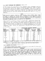
AC
GENERATOR
SPECIFICATIONS
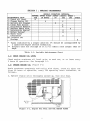
Model Number ...............................................
580.328330
Type of Equipment .......................
Revolving
Field a-c Generator
Rated Maximum
Continuous
a-c Power Capacity ......
2400 watts
(2.40 kW)
Rated Maximum
Continuous
Load Current ................
20.0 a-c amperes
Generator
Circuit
Breaker
Rating .....................
20.0 a-c amperes
Rated Voltage ...........................................
120 volts a-c
Phase ....................................................
Single Phase
Rated a-c Frequency ..............................
60 hertz at 3600 rpm
NL_ber
of Revolving
Field Poles .....................................
2
Driven
Speed of Revolving
Field ...................
3720 rpm at No-Load
Type of Revolving
Field Excitation..
Direct
Excited
(Bridge Rectifier)
Rated Maximum
Battery
Charge
Output ........
i0 amperes
at 12 volts d-c
Battery
Charge
Circuit
Breaker
Rating ..................
10 d-c amperes
ENGINE
SPECIFICATIONS
Engine
Manufacturer
..........................................
KAWASAKI
Manufacturer's
Model
Number ....................................
FA-210
Type
of Engine
..................
Single
Cylinder,
4-Stroke,
Air Cooled
Rated
Horsepower
......................................
5.0 at 3600
rpm
Fuel
Consumption
Ratio ...................
0.68
Ib/hp/hr
(310 gr/hp/hr)
Displacement
..............................
12.67
Cubic
Inches
(207 cc)
Compression
Ratio ............................................
6.4 to 1
Cylinder
Block
Material
.........................
High
Silicon
Aluminum
Ignition
System
Type ........................
Flywheel
Magneto
(with
Breaker
Points)
Recommended
Spark
Plug ........................
Resistor
Type
14 mm _
NGK ......................................................
BMR-6A
CHAMPION
..................................................
RCJ-8
Set Spark
Plug
Gap
to ................
0.023-0.027
inch
(0.6-0.7
mm)
Set Breaker
Point
Gap
to ...............
0.01-0.02
inch
(0.3-0.5
mm)
Ignition
Timing
...........................
Fixed
at 23 degrees
BTDC
Engine
Speed
Governor
Type .......................................
Mechanical,
Fixed
Speed
Governor
Setting
.............................
3720
rpm at No-Load _
Air Cleaner
.........
Semi-dry
Type,
washable
polyurethane
element
with
ny!on
brush
starter
......................................
Manual,
Recoil
Rope
Type
Engine
Crankcase
Oil Capacity
.................
1.27
U.S.
pint
(600 cc)
Recommended
Oils ........
Use oil
classified
"For
Service
SC, SD or SE"
Primary
Recommended
Oil ...........
SAE
10W-30
Multiple
Viscosity
_
Acceptable
Substitute
...................................
SAE
30 Oil
SAE
10W-40
OIL
IS NOT
RECOMMENDED
Maximum
Permissible
Inclination
for Continuous
Operation
without
Lubrication
Problems
.................
20 degrees
any direction
Fuel
Tank
Capacity
.....................
2.34
U.S.
gallons
(9.0 liters)
Recommended
Fuel
Primary
Recommended
Fuel ..........
UNLEADED
Automotive
Gasoline
_e_
Acceptable
Substitute
.....
Leaded
REGULAR
Grade
Automotive
Gasoline
Canada requires
the use of RESISTOR spark plugs,
in compliance
with the radio noise limitations
(radio
frequency
interference)
order issued by the Ministry
of Communications
of the Canadian
Telecommunications
Regulations
Branch.
At 3720 rpm the generatorts
a-c output
will
be 62 hertz.
This
slightly
high engine speed setting
at no-load helps ensure that
engine speed (and a-c frequency)
do not drop excessively
when
heavier
electrical
loads are applied.
Use of a multiple
viscosity
oil
will
contribute
to easier
starting
in cold weather.
Use of UNLEADED
gasoline
in a 4-cycle
engine
contributes
to increased
valve
life
by reducing
lead
and and
carbon
high
quality
REGULAR
grade
gasoline
may
be used,
LEADED
gasoline
is the primary
recommended
fuel.
deposits.
A
however,
UN-
SECTION
1.1-
INTRODUCTION
This
OWNER'S
_ANUAL
familiarizing
the
all
equipment
equipment
tion.
1.2-
been
and!or
misuse
will
the
Study
help
property,
or
abuse,
INFORMATION
prepared
with
equipment.
This
GENERAL
especially
handling,
for
operation
the
and
the
Manual
carefully
and
prevent
possible
injury
that
improper
might
be
procedures,
caused
or
purpose
of
servicing
of
comply
or
damage
with
to
by
carelessness,
incorrect
applica-
SAFETY
Prior
ROLES
ROLES
to
handling,
operating
FOR
SAFE
OPERATION
at
must
be
complied
with
damage
The
has
personnel
applicable
instructions.
1 -
to
equipment
following
found
and/or
this
the
All
or
property.
definitions
throuqhout
or
servicing
this
equipment,
study
the
front
of
this
Manual
carefully.
fully,
to help
avoid
personal
injury
apply
to
DANGER,
CAUTION
and
NOTE
blocks
Manua!:-
DANGER!
heading
will be found handling,
operating
and servicing
inthat,
if not complied
with
fully,
may result
in persona]
Under
this
structions
injury.
CAUTION!
Under
this
structions
heading
that,
if
will
not
be
found
complied
handling,
operating
with
fully,
may
and
result
servicing
in damage
into
equipment.
NOTE
be
Under
heading
special this
emphasis.
found
explanatory
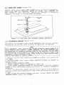
EQUIPMENT
DESCRIPTION
This
ator
equipment
set.
The
is
a gasoline
engine-driven,
generator
may
be
used
phase,
60
hertz,
a-c
(2.4
kW)
of
electrica!
circuit
breaker
will
of
electrical
power
open
the
connected
to
frequency
slightly
speed
trical
rpm
by
frequency
will
high
(and
a-c
loads.
be
60
engine
a
electrical
mechanical
are
directly
hertz;
speed
frequency)
revolving
operate
loads
exceeds
field
a-c
volts,
not
to
of
if
20.0
a-c
genersingle
2400
watts
current.
the
current
A
amperes.
is directly
attached
engine.
Engine
speed
is
maintained
at
to and
with
no
approxi-
governor.
Engine
speed
and
generator
proportional.
Thus,
at
3600
rpm
a-c
at
3720
rpm
a-c
setting
at
no-load
do
120
devices
requiring
up
or
up
to
20.0
a-c
amperes
unit's
a-c
output
circuit
The
generator's
revolving
field
(rotor)
driven
by
a 4-cycle,
air-cooled,
gasoline
electrical
loads
connected
to
the
generator
mately
3720
a-c
output
require
will
1.3-
requirements
that
statements
drop
frequency
helps
excessively
is
ensure
under
62
hertz.
The
that
engine
heavier
elec-
In addition
to its a-c power capability,
the generator
may be used to
recharge
a discharged
12 volts,
automotive
or utility
type storage
battery.
When properly
connected
to the discharged
battery,
an
operating
generator
will
supply a maximum charge rate of approximately
i0 d-c amperes at 12 volts.
The maximum rate of charge will
gradually
decrease
as the connected
battery
approaches
a i00 percent
state
of
charge.
1.4-
RECEIVING
AND
HANDLING
Upon
receipt,
completely
remove
the
generator
from
its
shipping
carton
and
from
any
shipping
pallet
to which
it might
be
attached.
Remove
all
packing
material
from
around
the
generator.
Inspect
the
unit
carefully
for
any
damage
that
might
have
occured
during
shipment.
In addition
with
the
the
REPAIR
to
this
OWNERtS
MANUAL
a
generator.
To
order
additional
PARTS
section
of
the
Manual.
BATTERY
CHARGE
Manuals
or
CABLE
Cables,
is
shipped
refer
to
CAUTION!
DO
NOT
been
properly
Manual.
Any
properly
to crank
prepared
attempt
to
serviced
with
and
start
for
use,
crank
or
the
the
generator
engine
as
outlined
in
Section
start
the
unit
before
recommended
oil
will
result
until
it has
2 of
this
it
has
been
in
an
engine
SECTION
2 - OPERATING
DO
i.
DO
with
PI_PARATION
all
SAFETY
DON'T
CHART
i. DON'T operate
the unit inside
any enclosure
that might
obstruct
the free flow of cooling
air.
2. DO check oil level before
start2. DON'T operate
the unit inside
any room or enclosure
where exup or at least every
5 hours of operation.
haust fumes might accumulate
and
result
in carbon
monoxide
poisoniing.
3. DO disconnect
electrical
loads
3. DON'T overload
the generator.
The
total
of
all
connected
loads
from panel
before
should
not
exceed
2400
watts
(2.4
starting
or stopping
the engine.
kW), or 20.0 a-c amperes.
4. DON'T touch areas around
the
4. DO comply
with
instructions
in
engine
exhaust
muffler.
These
this Manual
when
charging
a battery.
areas are HOT.
5. DON'T
handle
electrical
5. DO operate
the generator
only
on
equipment
while
standing
in
surfaces
that are as level as possible.
water,
while barefoot,
or while
hands
or feet are wet.
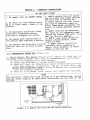
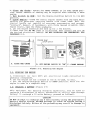
2.1-
comply
AND
INSTRUCTIONS
BEFORE
RULES.
USE
(Figure
2-1)
a. Check
Enqine
Oii
Level
(Figure
2-1):Check
oil
level
and
(if
necessary)
fill to proper
level with the recommended
oil as follows:(I) Place the generator
on a level surface.
(2) Remove
OIL FILL PLUG by turning
counterclockwise.
(3) Check
oil level. Oil should
be at point
of overflowing
the 0IL
FILL
PLUG opening.
If necessary,
add oil
to that
level.
See
ENGINE
SPECIFICATIONS
CHART
at front of Manual
for recommended
oils and crankcase
capacity.
(4) When oil is at proper
level,
install
and tighten
OIL FILL PLUG.
The
bearing
bearing.
which
NOTE
revolving
field
rotates
on a pre-lubricated,
requires
no additional
lubrication
for the life
OIL FIL_
PLUG
Figure
2-1.
_
\
_
Engine
_
_
Oil
..........
Fill
and
:_ ,
""_ OIL DRAIN
PLUG
Oil
Drain
Locations
sealed
of the
b.
Fill
Fuel
Tank:Remove
Fuel
Tank
FILLER
CAP
by
turning
counterclockwise.
Fill
Fuel
Tank
with
clean,
fresh
gasoline
as
recommended
in the ENGINE
SPECIFICATIONS
CHART
at front
of Manua!.
Install
and
tighten
FILLER
CAP.
DANGER!
Gasoline
is extremely
FLAMMABLE
and its vapors
are EXPLOSIVE.
DO NOT
permit
smoking€
open flame
or sparks
in the vicinity
while
handling
gasoline.
Avoid
spillage
of gasoline
on a hot engine.
Comply
with all
laws
regulating
the storage
and handling
of gasoline.
Never
store
the
generator
with fuel in tank where
gasoline
vapors
might
reach
an open
flame,
spark
or pilot
light
(such as on a furnace,
water
heater,
dryer,
etc.)- FIRE or an EXPLOSION
might
result.
C.
120
Volts
Cord
grounded
cord
sets
Wire
gauge
of
cord
anticipated
current
Sets:Use
only
high
quality,
well
insulated,
with
the
generator's
120
volts
a-c
receptacles.
sets
must
be
large
enough
to handle
the
maximum
draw
of
connected
electrical
loads.
Cord
sets
that
are
excessively
long
or
that
are
rated
cause
a
voltage
drop
and
will
overheat.
recommended
wire
gauges,
based
on
the
current
draw
in amperes.
COUNT
(AMPERES}
2-3
4-5
6
8
i0
12
14
16
18
2O
Table
2.2-
OPERATING
2-1.
Recommended
....
LENGTH
0-50
18AWG
16 AWG
16 AWG
16 AWG
16 AWG
14 AWG
14 AWG
12 AWG
12 AWG
I0 AWG
Wire
at
too
low
an
Table
2-1
cord
set
length
OF,,,..CORD SET
51-100
..........18 AWG
16 AWG
16 AWG
14 AWG
14 AWG
14 AWG
12 AWG
12 AWG
10 AWG
8 AWG
Gauges
of
120
amperage
will
lists
minimum
and
the
load
IN FEET
101-150
18 AWG
16 AWG
14 AWG
12 AWG
12 AWG
12 AWG
l0 AWG
l0 AWG
8 AWG
8 AWG
Volts
Cord
Sets
LOCATION
Comply
with
the
the generator:-
following
rules
pertaining
to operating
location
of
a. Place
the generator
on a level surface.
Maximum
tilt of the engine
in any direction
must
not exceed
20 degrees,
or engine
lubricating
problems
may result.
b. Never
operate
the generator
where
it will be exposed
to flooding,
excessive
moisture,
dust, dirt or corrossive
vapors.
c. Provide
adequate
ventilation.
Never
operate
the generator
inside
any
room
or enclosure
where
exhaust
fumes
might
accumulate
and
endanger
people.
d. Never
run the generator
inside any room or enclosure
that might
obstruct
the free flow of cooling
air. Without
adequate
cooling
air, the
unit will
quickly
overheat,
causing
serious
operating
problems
and
possible
damage
to equipment
and/or
property.
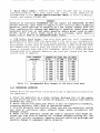
2.3-
DON'T
OVERLOAD
THE
GENERATOR
(Table
2-2)
DO NOT
exceed
the
generator's
rated
WATTAGE
and/or
AMPERAGE
capacity
for
continuous
operation.
Before
connecting
electrical
loads
to panel
receptacles,
add
up the
WATTS
(or the AMPERES)
required
to operate
those
loads.
Rated
watts
and/or
amperage
can usually
be found
on the
nameplate
of lights,
appliances,
motors,
etc. The
total
of all loads
being
powered
at one
time
should
not
exceed
2400
watts
or 20.0
a-c
amperes.
NOTE
Some
electric
motors
(such
as
saws,
drills,
etc.)
require
more
watts
of
power
or
amperes
of current
than
is stated
on
their
nameplate,
when
the
motor
is being
put
to
hard
use.
For
example,
a saw
that
is used
to
cut
through
extremely
difficult
material
may
require
3 to 4 times
more
wattage
or
amperage
than
is
stated
on
its
nameplate.
Some
electric
Capacitor,
or
motors
Split
Phase
(such
type)
as
Universal,
require
more
Repulsion-Induction,
amperes
of
current
for
starting
than
for
continuous
on-speed
operation.
Approximate
starting
and
running
current
(in
amperes)
is
listed
in
Table
2-2.
To
use
the
chart,
find
the
TYPE
OF
MOTOR
and
its
RATED
HORSEPOWER
on
the
motor
nameplate.
Then,
in
the
chart.
MOTOR
HORSEPOWER
locate
2.3
3.3
1/6
1/4
1/3
approximate
UNIVERSAL
.........
MOTORS
3.3
4.2
5_0
1/2
3.8
5.0
3/4
7.1
8.3
1
i-1/2
8.3
2
3
5
I
10.4
e
STARTING
norsepower
Approximate
THE
ENGINE
in tnls
Motor
(Figure
MOTORS
and
amperes
AMPERES
......
SPLIT
PHASE
MOTORS
I0.0
16.2
.........
_MOTORS
c±assltlcatlon
Running
running
CAPACITOR
5.0
7.1
8.1
10.8
15.8
19.2
26.7
32.5
43.3
62.5
6.3
12.3
16.7
nlgner
and
I INDUCTION
25.0
40.0
"_ Motors
ot
used.
Table
2.4-
starting
APPROXIMATE
STARTING
............ ,IREPULSION
APPROXIMATE
RUNNING
A_PERES
RATING
the
Starting
7.1
8.8
ii. 3
15.0
21.7
25.0
35.0
42.5
56.7
81.7
are not
16.3
21.7
k
generali?
Requirements
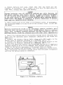
2-2)
a. Disconnect
Electrical
Loads:Disconnect
or turn OFF all electrical
loads connected
to generator
receptacles.
CAUTION!
Never
start
or stop the engine
with
electrical
loads
connected
and
turned
on. The generator
will
supply
its rated
voltage
and frequency
only at its correct
rated operating
speed. Some electrical
devices
may
be damaged
by incorrect
voltage
and/or
frequency.
In addition,
starting the engine
with
electrical
loads
applied
imposes
a heavy
load at
lower
operating
speeds
where
adequate
power
is not yet available
and
may shorten
engine
lifeo
b. Close
the
Choke:Rotate
the CHOKE
CONTROL
to its FULL
CHOKE
position.
Lesser
amounts
of choking
may
be required
when
starting
a warm
engine.
c. Set
Switch
to RUN:Set
the
Engine-Run/Stop
Switch
to its
RUN
position.
d. Crank
Engine:Grasp
the recoil
starter
handle
with
one hand
while
holding
the
generator
carrying
handle
with
other
hand.
Pull
the
starter
handle
out
rapidly
to
overcome
compression
and
prevent
"kickback".
Repeat,
if necessary,
with
Choke
opened
slightly.
When
engine
starts,
open
the Choke
gradually.
e. Let
the engine
stabilize
and warm
up for a few minutes.
f. Check
that
the AC ON light
is illuminated.
Then
connect
and
turn ON
the desired
electrica!
load(s).
DO NOT
OVERLOAD
THE
GENERATORSEE
PARAGRAPH
2.3.
ENGINE
RUN/
SWITCH
START£Ft
HANDLE
I
A.
CLOSE
THE
CHOKE
B.
SET
ENGINE
SWITCH
TO
"ON _
C.
CRANK
ENGINE
i
Figure
2.5a.
STOPPING
THE
Disconnect
2-2.
Starting
CHARGING
(or
A
Engine
ENGINE
turn
OFF)
all
generator
receptacles.
b. Let
the engine
run
for a minute
c. Set
the
Engine-Run/Stop
Switch
engine
to come
to a complete
stop.
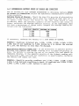
2.6-
the
BATTERY
This
equipment
has
recharge
a discharged
battery.
Te
recharge
(Figure
electrical
or
two at
to STOP
loads
no-load,
position,
connected
to
cool.
wait
for
to
the
2-3)
battery
charging
capability,
may
be
12
volts,
automotive
or
utility
type
a 12
volts
battery,
proceed
as
follows:-
used
to
storage
CAOTION!
DO NOT
attempt
to recharge
battery
charge
system.
DO
discharged
battery.
Either
equipment.
any
6 volts
battery
using
the generatorWs
NOT
attempt
to crank
an engine
having
of the preceding
may
result
in damage
a
to
a.
Remove
battery
vent
clogged.
If
necessary,
caps.
Then,
install
vent
caps.
Check
that
vent
cap
use
a length
of
fine
wire
to
caps
onto
battery.
holes
open
are
holes
not
in
DANGER!
Storage
batteries
give off EXPLOSIWE
hydrogen
gas while
charging.
DO
NOT permit
smoking,
open flames,
sparks,
or spark producing
equipment
in the vicinity
while
charging
a battery.
NEVER
use a match,
lighter,
or any other source
of heat to provide
lighting
while checking
battery
fluid
level. The danger
of explosion
is greatly
diminished
if battery
vent caps are installed
while charging.
b. Check
electrolyte
add
DISTILLED
WATER
TAP
WATER.
fluid
level
in all
battery
to
bring
fluid
to
the
correct
cells,
if
level.
necessary,
DO
NOT
OSE
DANGER!
Battery
electrolyte
fluid
is an extremely
caustic
sulfuric
acid
solution
that can cause
severe
burns. DO NOT permit
fluid to contact
eyes,
skin,
clothing,
painted
surfaces,
wiring
insulation,
etc. If
spillage
occurs,
flush the affected
area with clear water
immediately.
c. Insert
the 2-prong
plug
of the Battery
Charge
Cable
(shipped
with
unit)
into
the
generator
panel
receptacle
indicated
by the
words
_12
VOLT
D.C.".
d. Connect
the
Battery
Charge
Cable
clamp
with
RED
handle
to the
battery
post
or terminal
indicated
by a POSITIVE,
POS or "+".
e. Connect
the
Battery
Charge
Cable
clamp
with
BLACK
handle
to the
battery
post
or terminal
indicated
by a NEGATIVE,
NEG or "-".
f. Start
the generator
engine.
The discharged
battery
will
receive
a
maximum
charge
of up to I0 d-c amperes.
This
maximum
charge
rate
will
reduce
as the battery
approaches
a i00 percent
state
of charge.
g. When
the
battery
has
recharged,
shut
the
generator
engine
down.
Then,
disconnect
the Battery
Charge
cable
from
the panel
receptacle
and
from
the battery
posts
or terminals.
t
_
RED
Figure
2-3.
Charging
a
Battery
2.7-
DETERMINING
BATTERY
STATE
Use
an
automotive
type
OF
CHARGE
and
CONDITION.
tions
carefully.
OF
BATTERY
Follow
CHARGE
AND
CONDITION
HYDROMETER
to
the
hydrometer
determine
battery
STATE
manufacturer's
instruc-
Batter_rl
State
of
Charge:Check
the
specific
gravity
fluid
in al!
battery
cells.
Write
down
the
reading
of
is
taken,
then
return
the
fluid
to
the
cell
from
withdrawn.
When
the
specific
gravity
known,
calculate
the
average
specific
not
have
a percentage
of
charge
scale,
tained
with
the
following:-
SPECIFIC
GRAVITY
1.260
1.230
1.200
1.170
If
necessary,
recharge
EXAMPLE:-
Readings
1.230.
Sum
of
1.224.
of
The
the
battery
obtained
are
all
readings
battery
is
is
less
7.345.
than
of
the
gravity.
compare
PERCENT
to
a
1.230;
OF
100%
75%
50%
25%
100%
fluid
in
all
cells
If
the
hydrometer
the
average
reading
is
does
ob-
CHARGE
STATE
1.220;
Divide
by
75%
charged.
of
electrolyte
each
cell
as
it
which
it
was
OF
CHARGE.
1.230;
6
to
obtain
1.210;
the
1.225;
average
Determininq
Battery
Condition:If the difference
in specific
gravity
_-etween
the highest
and lowest
reading
cell
is 0.050 (50 points)
or
more,
the battery
is nearing
the end of its useful
life and should
be
replaced.
However,
if the specific
gravity
of the highest
reading
cell
is less than 1.200, the test for condition
is questionable.
Recharge
the battery
and repeat
the test.
EXAMPLE:Specific
gravity
readings
are 1.230;
1.220;
1.230;
1.225; 1.230. Battery
condition
is good. If readings
are 1.250;
1.240;
1.240;
1.240;
1.210battery
is worn out.
10
1.210;
1.180;
SECTION
3 -
BEFORE
USE
X
PERIODIC
MAINTENANCE
HOU_Y
OPERATING
INTERVAL
AFTER FIRST
EVERY
EVERY
EVERY
20 HOURS
50
_ i00 _
200 .....
OTHER ......
MAINTENANCE
TASK
ii. check
0il level
2. Change
Enqine
Oil
3. Service
Air Cleaner
_
_
14, Clean FuelIIIscreen .................
5. Decarbonize
Muffler
X
X
X
x
X
X
x
i71DeC'arb0nize
Engine*
8. Reface Valves*
:9. Check Valve
Clearance*
10. Prepare
for
Storage
**
I
....
X
x
Tasks
indicated
by a single
asterisk
(_) should
be accomplished
a qualified
engine
service
technician.
Prepare
unit for storage
if it is to remain
idle longer
than
days.
3.1-
CHECK
Table
3-1.
OIL
LEVEL
ENGINE
Check
engine
crankcase
5 hours
of
operation.
3.2-
CHANGE
ENGINE
Drain
crankcase
first
20
hours
follows:-
a.
X
Operate
oil
level
See
Paragraph
OIL
(Figure
completely
of
operation,
engine
Periodic
until
and
Maintenance
prior
to
2.1.
each
use,
or
refill
with
clean,
every
i00
operating
thoroughly
warmed
up,
then
fresh
hours
shut
least
oil
after
thereafter,
down
lllJ
il!/
11
II
_
--OIL
Engine
at
every
3-1)
OIL FILL--J)"
3-1.
30
Chart
______
Figure
by
OIL
FILL
and
OIL
DRAIN
PLUG
DRAIN
PLUGS
the
as
b. Clean
areas
from
entering
c.
Remove
OIL
d.
Remove
container.
around
O!L
engine.
FILL
PLUG.
OIL
e. When
foot-pounds
al!
DRAIN
oil
(1.4
PLUG
FILL
and
and
drain
has
drained,
kg-m).
OIL
DRAIN
oil
install
PLUGS,
completely
OIL
Install
3.3-
and
SERVICE
Service
AIR
the
frequently
service
tighten
OIL
CLEANER
engine
the
(Figure
air
if operating
air
cleaner,
FILL
prevent
into
DRAIN
PLUG.
f. Refill
with
recommended
oi!
through
the
OIL
FILL
slowly.
Oil
level
is correct
when
oil
reaches
point
OIL
FILL
PLUG
opening.
See
ENGINE
SPECIFICATIONS
Manual
for
recommended
oils.
g.
to
a
dirt
suitable
Tighten
to
PLUG
opening.
of overflowing
CHART
at
front
!0
Pour
the
of
PLUG.
3-2,
cleaner
3-3)
every
50
hours
under
extremely
dirty
proceed
as
follows:-
of
or
operation,
dusty
more
conditions.
To
COVER
.................
i
Fire
3-2.
a. Remove
PANEL.
Remove
4
screws
b.
c.
Unsnap
Wash
d.
oil
Saturate
and
to
e.
f.
Wash
PLATE
in
Install
PLATE.
g.
Install
h.
Engage
and
retain
End
the
ELEMENT
that
LATCH,
in
ELEMENT
remove
Panel
Figure
retain
END
PANEL
3-3.
Air
to
cradle,
then
remove
COVER,
ELEMENT
kerosene.
Squeeze
dry.
in
excess
kerosene,
ELEMENT
with
slot
on
COVER
with
LATCH.
clean,
oil.
dry
nylon
with
fresh
with
engine
a
"brushes"
tang
on
clean,
air
12
Cleaner
and
oil.
Assembly
then
remove
END
PLATE.
Squeeze
lint-free
facing
outward.
cleaner
CASE,
to
distribute
cloth.
install
COVER
3.4-
CLEAN
FUEL
(F ig u r e
SCREEN
3- 4 )
Remove,
clean
and inspect
FUEL
SCREEN
every
50 hours
of operation.
Remove
FUEL TANK CAP, BREATHER,
GASKET
and FILTER.
Clean
BREATHER
and
FUEL
SCREEN
in clean
gasoline.
Replace
any
damaged
or defective
component.
Reinstall
in reverse
order of removal.
----FUEL
.......
TANK
CAP
BREATHE
GASKET
FILTE
/
Figure
3.5-
3-4.
DECARBONIZE
The
engine
Decarbonize
Fuel
MUFFLER
Tank
Cap,
(Figure
is equipped
the muffler
with
every
Breather,
Gasket
and
Filter
3-5)
a SPARK
50 hours
ARRESTOR
type
of operation,
exhaust
muffler.
as follows:-
NOTE
This
equipment,
when
used
grass
covered
land
requires
be
maintained
in effective
of
California,
the
preceding
California
Public
Resources
Federal
laws
apply
a. Remove
4 screws
rear
PANEL.
b.
Remove
SCREWS
exhaust
muffler.
c.
Remove
SPARK
d.
Inspect
e.
Clean
SCREEN
if
defective.
f. Start
blow
out
it
cool.
g.
When
ARRESTOR
on
federal
that
that
ARRESTOR
GASKET,
replace
SPARK
ARRESTOR
torn,
perforated,
the
generator
carbon
and
engine
SCREEN.
on
any
forest
covered,
brush
covered
or
a SPARK
ARRESTOR.
The
SPARK
A_RESTOR
must
working
order
by
the
operator.
In the
State
is required
by law
(Section
4442
of
the
Code).
Other
states
may
have
similar
laws.
retain
retain
lands.
rear
PANEL
SPARK
to
cradle,
ARRESTOR
SCREEN
then
and
remove
GASKET
the
to
SCREEN.
if damaged
SCREEN
in
excessively
engine
condensation.
and
and
exhaust
muffler
Retain
with
SCREWS.
13
or
defective.
non-flammable
dirty,
or
let
Then,
are
solvent.
otherwise
Replace
damaged
or
run
for
about
5-10
minutes
shut
the
engine
down
and
cool,
install
GASKET
and
to
let
SPARK
DANGER!
DO NOT
touch
may result.
e.
f.
Inspect
Install
a
hot
GASKET.
GASKET
muffler
or
Figure
REPLACE
SPARK
hot
adjacent
parts,
or
serious
burns
Replace
if torn or otherwise
damaged.
and PLATE,
retain
with SCREWS.
SPARKARRESTOR
3.6-
any
PLUG
SCREEN
.3-5. Spark
(Figure
Arrestor
Screen
3-6)
Replace
spark
plug
every
200 hours
of operation,
or if damaged
or
defective.
Use
replacement
spark
plug
as
recommended
in ENGINE
SPECIFICATIONS
CHART
at front of Manual.
Set gap on new or used spark
plug to 0.023-0.027
inch (0.6-0.7
mm).
a. Remove
COVER
by prying
upward.
b. Use a spark plug socket
wrench
to remove spark plug.
c. Set gap on spark plug as specified.
d. Install
spark
plug
with
gasket.
Tighten
plug
by hand until
it
firmly
seated.
Then,
tighten
an additional
3/4 to 1 turn
using
socket
wrench.
e.
Instal!
COVER.
__cov£R
S_RK
Figure
3-5.
Spark
Plug
14
Removal
is
a
3.7-
DECARBONIZE
Have
the
ENGINE,
carbon
head,
have
valves,
the
valves
3.8-
PREPAP_
If
the
a.
Operate
as
cleaned
piston)
refaced
UNIT
unit
storage
is
REFACE
to
FOR
be
VALVES,
from
every
and
the
CHECK
engine
i00
hours
adjusted
of
by
VALVE
CLF/%RANCE
combustion
operation.
an
engine
area
At
service
the
(cylinder
same
time,
technician.
STORAGE
unused
for
longer
than
30
days,
prepare
it
for
follows:the
engine
until
it
runs
out
of
gas.
b.
Let
the
engine
cool.
c.
When
engine
has
cooled,
remove
spark
plug
(see
Paragraph
3.6).
Then,
pour
about
2 or
3 tablespoons
of
clean,
fresh
engine
oil
into
spark
plug
opening
in engine
cylinder
head.
Crank
engine
several
times
to distribute
oil.
d.
Install
spark
plug
and
spark
plug
access
cover.
e. Slowly
pull
starter
handle
out
until
resistance
is felt,
indicating
that
engine
is on
its
compression
stroke.
This
will
close
both
valves,
to prevent
rusting
f. Wipe
exterior
cloth.
g.
Cover
the
of
the
surface
generator
and
cylinder
of
engine
store
interior.
and
generator
in
_5
a
clean,
dry
with
place.
an
oil-soaked
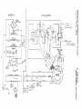
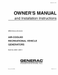
WI_.ING
DfAG
RAiv_
................
_
BRIDGE
T'3;,
t G,,_..a_.m
i C,'_.3
©
F.,,_
G_EEN
DIODEI
POWER
TO
©
TANK.
_.OUKt"_IA,fG
_A,$ooYL
\
...... 1
®
BRIDGE
RECTIFIER
0
IGN._o--_
+
_
@
@
ba
®
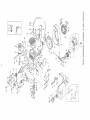
2400 WATT
PORTABLE
AC GENERATOR
MODEL NUMBER 580.328330
I7
X
u_
H
_N
o
tm
,_ItJ
-A"
ASSEMBLE
USING LOCKT!TE
15\
16
17
ffl
2O
0
2t
f
J
?
_
3_r-ITEMS
SUPPLIED WITH ENGINE
8
_n
EXPLODFn
Dra_ing
VIEW OF AC GENERATOR
Nnmber 65798-A
O
i
w
_u
o
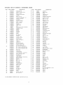
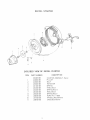
EXPLODED
Drawing
VIEW OF AC GENERATOR
Numbe[
65798-A
ITF_/_ PART NUMBER
1
65188
2
66836
3
66462
4
66834
5
66432
6
22097
7
52243
8
51755
9
66837
I0
66443A
ii
66443B
12
49809
13
67022
]4
66365
15
39253
16
66389
17
65785
18
65791
19
65795
20
66448B
21
66454
22
66825
23
66449B
24
66849
25
66386
26
67025
27
45771
28
66850
29
46526
30
66894
31
49815
32
67444
33
52856
34
67435
35
67210
36
67451
37
6'7462
38
22129
39
49810
DESCRIPTION
ENGINE5 Horsepower
KawasakiFA210
CLAMP,
Fuel
Line
(2 Req'd)
BRACKET,
Muffler
Support
(I Req'd)
NUT,
Flanged
LockM8-!.25
(4 Req'd)
MUFFLER,
Spark
Arrest
(i Req'd)
WASHER,
LockM6
(4 Req'd)
(i
Req'd)
CAPSCREW,
Hex
HeadMI0-1.50
x 60mm
(I Req'd)
CAPSCREW,
Hex
HeadM10-1.50
x 16mm
(I Req'd)
HOSE,
Fuel300mm
long
(I Req'd)
MOUNT,
VibrationEngine
(2 Req'd)
MOUNT,
VibrationGenerator
(2 Req'd)
WASHER,
FlatMI0
(i Req'd)
GROMMET,
Lead
Outlet
(i Req'd)
HOUSING,
Engine
Adapter
(i Req'd)
CAPSCREW,
Hex HeadM8-1.25
x 20mm
(4 Req'd)
FAN,
Cooling
(i Req'd)
ROTOR
ASSEMBLY
(! Req'd)
BEARING,
Ball
(i Req'd)
RECTIFIER,
Battery
Charge
(i Req'd)
BOLT,
RotorM8-!.25
x 190mm
(i Req'd)
STATOR
ASSEMBLY
(i Req'd)
CARRIER,
Rear
Bearing
(I Req'd)
BOLT,
StatorM6-1.00
x 90mm
(4 Req'd)
SCREW
(Taptite)M5-0.80
x 15mm
(7 Req'd)
ASSEMBLY,
Brush
(i Req'd)
COVER,
Bearing
Carrier
(i Req'd)
NUT,
HexM8-1.25
(2 Req'd)
BOARD,
Bridge
Rectifier
(i Req'd)
WASHER,
LockMI0
(2 Req'd)
CLAMP,
Fuel
Line
Support
(i Req'd)
SCREW,
MachineM5-0.80
(i Req'd)
WASHER,
SerratedM5 (I Req'd)
NUT,
Flanged
LockM5-0.80
(i Req'd)
NUT,
WingM5-0.80
(i Req'd)
DECALGround
(i Req'd)
WASHER,
Flat
(Special)M8
(i Req'd)
DIODE
ASSEMBLY
(i Req'd)
WASHER,
LockM8 (2 Req'd)
WASHER,
FlatM8 (2 Req'd)
19
28
_H
M
0
26
33
\
..4¢3
4O
14
3(
0
29
41
21
lm
o
i
w
EXPLODED
Drawing
ITEM
VIEW OF CRADLENumber
65799-A
PART
NUMBER
2400
WATT
GENERATORS
(Sears
580.328330)
DESCRIPTION
1
2
3
4
5
6
7
8
9
i0
ii
12
66394
66456
66457
66453
66455
66817
66818
66819
66820
66821
66822
66828
13
6682'7
RECEPTACLE12 Volts
d-c
(I Req'd)
RETAINER,
12 Volts
d-c
Receptacle
(i Req'd)
SCREW,
MachineM3-0.50
x 5mm
(2 Req'd)
SCREW,
Machine
(with
Lock
Washer)M5-0.80
14
15
16A
16B
16C
66450
66368
66802A
66802B
66802C
(25
Req'd)
COVER,
Handle
(4 Req'd)
TANK,
Fuel2.34
U.S.
Gallons
CAP,
Fuel
Tank
(i Req'd)
BREATHER,
Fue!
Tank
(i Req'd)
GASKET,
Fuel
Tank
Cap
(i Req'd)
17
64680B
18
66391-B
19
65787
20
21
22
23
65788
66392
66393
66397D
24
66829
25
26
27
28
29
30
31
32
33
34
66823
66824
66398C
67103
67459
66831
66864
66838
66880
66839
35
52749
36
52619
37
67444
38
39
51716
66395-21
40*
41"
42*
++
BASE,
PANELPANEL,
*
++
Cradle
Engine
Muffler
(i
End
(i
Req'd)
(i Req'd)
Req'd)
PANEL,
Generator
End
(I Req'd)
PANEL,
Receptacle
and
Control
(i Req'd)
SWITCH,
Engine-Run/Stop
(i Req'd)
RECEPTACLE120
Volts
a-c,
15 Ampere
(2 Req'd)
BREAKER,
Circuit20 a-c
Amperes
(i Req'd)
BREAKER,
Circuiti0 d-c
Amperes
(i Req'd)
COVER,
Spark
Plug
Access
INDICATOR,
Fuel
Level
(I
CABLE,
DECAL,
CRADLE,
CRADLE,
PLATE,
RIVET-
Battery
Charge
Receptacle
and
Engine
End
(i
Generator
End
Data
(i Req'd)
3 mm
(2 Req'd)
DECAL,
DECAL-
Choke
(I Req'd)
Hot
Caution
(i
DECALDECAL-
Starting
Warranty
SCREW
RIVET,
Req'd)
(i Req'd)
Req'd)
(i Req'd)
Control
Panel
Req'd)
(I Req'd)
(i
Req'd)
Req'd)
Data
(i
(i Req'd)
(Crimptite)Black
Anodized-
(i
(8
Req'd)
Req'd)
4mm
(8
Req'd)
DECALU.S.D.A.
(i Req'd)
FILTER,
Fuel
(I Req'd)
SHIELD,
Fuel
Tank
Heat
(l Req'd)
NUT,
Hex
LockM5-0.80
(6 Req'd)
SCREW,
MachineM5-0.80
x 12 mm
(2 Req'd)
SCREW,
MachineM5-0.80
x 20mm
(I Req'd)
WASHER,
SerratedM5
(i Req'd)
NUT,
Hex
M5-0.80
(i Req'd)
WIRE,
Ground
(Green)(i Req'd)
DECALUnleaded
Fuel
DECALDECAL-
66832A
Engine
MANUAL,
These
Parts
NOT
SHOWN
Air
Cleaner
Lubrication
Owner's
Supplied
with
21
(i
Req'd)
Engine
x
12mm
m
x
i'-
103
m
t05
<
m
55--_
I10
57--_b
o
-1-t
s6- D
99
6O
64
59
44
46
5O
65
t3
53
36
47
49
48
52
\
78
5i
77
76
22
21
I6
35
8O
23
82
8!
74
I
79
87
79
i8
88
i7
2O
7
EXPLODED VIEW OF KAWASAKI
ITEM
PART
NUMBER
5 HORSEPOWER ENGINE
I
2
100-65188
t01.65188
HEAD,Cylinder
GASKET.
Cylinder
3
102o65188
BOLT
4
103-65188
COVE R .ValveC hamber
5
104-65188
GASKET
6
t05-65188
BOLT
7
106-65188
CLEANER
8
9
t07,65188
108.65188
COVE R, Air Cleaner
ELEMENT
10
109-65
P LATE
t 1
110,65188
CASE.
Air Cleaner
12
11 t_65188
BOLT
(6 x 80)
13
112-65188
GASKET
14
] t 3,65188
TUBE
15
114.65188
PIPE
16
] 8B
66432
Head
16 x t2)
ASSEMBLY
Air
Air Cleaner
,Rubber
MUFF
LE R. E×hau51. (Comptele)
116-65188
AR REST E R .SPark
18
116-65188
GASKET
19
117-65188
SCREW
20
118-65188
WASHER
2!
t 19-65!88
GASKET
22
120-65188
STUD
23
121-65188
NUT
24
122-65188
WASHE
25
t23-65188
VALVE
Intakc _
Exhaust
(8 nlrn)
R
26
124-65188
VALVE
27
125-65188
SPRING.Valve
28
126-65188
SEAT
29
127-65188
TAPPET
30
128.65188
CAM SHA F T
31
129-65188
PISTON
(Standard)
130,65188
PISTON
10 25ram
OS)
131,65188
PISTON
(0 50ram
OS}
132-65
! 88
56
57
58
59
60
61
(8 x 56)
17
32
ITEM
DESCRIPTION
Valve
S!::,rir_!l
SET.
Piston
Ring
133-65188
SET
Piston
Ring{O25mmOS)
134-65188
SET
Piston
Ring
33
135_65 t 88
Pf N. P ist_m
34
136-65t88
RING
35
137-65188
CR AN K SHAFT
36
138,65188
ROD ASSEMBL
37
! 39-65188
BOLT
38
140,65188
WASHER
39
14 1-65188
ARM
40
41
142-65t88
143-65188
CASE ASSEMBLY
BEARING
plain
42
144,65188
GASKET
43
t45,65188
BOLT
44
!46-65188
SEAL.Oil
45
147.66188
Pt N.Dowel
46
148-65188
CA R BU R ETO R
47
149,65
i NSU LATOR
48
150-65188
49
151-65t
50
152-65188
GASK
51
153o65!88
NUT
52
154-65188
WASH
53
155.65188
STUD
_88
88
OS)
Y Connecting
Connecting
Rod
Lock
Splasher
(10
PIPE.
Connecting
x t4}
GAS K E T
ET
16 ram)
ER
GAUGE.
55
66802A
CAP
Fuel
RCJ8
Fuel
Level
Tank
or equivalen!
spark
plug
23
DESCRIPTION
GASKET
668028
BREATHER
156-65188
WIRE.
157-65188
HOUSING
!58-65188
CASE .Spiral
Far_
159-65t88
COVER
160-65188
COVER
161-65188
BOLT
16 x i0)
t05,65188
BOLT
(6 x 12_
162-65188
163-65188
SCREW (Sx
IO}
ARM ,Governor
t64-65!88
BOLT
153-54188
154-65188
NUT (6 ram}
WASIHER
165,65188
ROD .Governor
!66-65188
SPRING
Link
167-65188
168_65!88
SPRING
.Governor
169-65188
t70-65188
ADJUSTER
Spring
NUT (6 ram)
171-65188
BASE.
172-65188
BEARING,Ball
78
79
80
173.65188
GASKET
174-65188
BOLT
16 x 30)
t75-65188
SEAL
Oil
81
82
83
84
85
86
87
88
89
176-65t88
GOVERNOR
177-65188
t78.65188
SLEEVE
Governor
TIP.Governor
179-65188
WASHER
106
!07
108
t09
110
t11
1t2
t13
Inlet
66391B
CHAMPION
(0 50ram
NUMBER
66802C
62
63
64
65
66
67
68
69
7O
71
72
73
74
75
76
77
90
91
92
93
94
95
96
97
98
99
100
101
102
t03
104
105
Snap
54
* UseNGK,BMR6A
(Slandard)
PART
Cyiinder
Head
Cylinder
16 x 25)
BRACKET
Side
(6205)
t80.65188
PIN Snap
18t-65188
WASHER
182.65188
GAUGE,Oil
183-65188
O-RING
184-65188
FLYWHEEL
185,65188
COl L Ignilion.
BREAKER
ASS'Y
t86-65188
Level
187-65188
CONDENSER
188.65188
189-65t88
BREAKER
BRUSH
190-65188
CLAMP
191-65t88
CLAMP
192-65188
COVER
193.65t88
RING
Contact
Contact
194-65188
BOLT
t95-65t88
SCREW
(4 x 8)
196-65188
SCREW
(4 x 20}
(5 x 201
197-65t88
GROMMET
198.65188
NUT
t99,65188
KEY
114 ram)
200-65188
WASHE
R
201-65t88
SPARK
PLUG'
202-65188
20365188
CAP. Plug
SPRING
204,65188
205-65188
STARTER
ASSEMBLY
BOLT
16 x 10}
206,65188
[DE CA L
207-65188
DECAL
208-65188
DECAL
Recoil
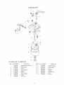
CARBURETOR
3
2
4
i0
\
12 ....
15
EXPLODED VIEW OF CARBURETOR
ITEM
PART NUMBER
ITEM
DESCRIPTION
148-65188
CARBURETOR
]
2
209-65188
2t0-65188
SHAFTChoke
3
4
5
6
7
8
9
10
2t1-65t88
212-65188
2t3-65t88
214-65188
225_65188
216-65188
217-65188
218,65!88
SCREW
1I
t2
13
14
ASSEMBLY
VALVEChoke
JET Pilo; {#37
SCREW.
Pilol
SPF_fNG
SHAFT
VALVE
15
16
I7
18
19
5)
Throttte
_hrott_e
SCREW
SCREW
Stop
24
PART NUMBER
2t9-65188
220-65t88
221-65188
222-65188
223-65188
224-65188
225-65188
226-65188
227-65188
DESCRIPTION
JET, Main
{#77
NOZZLE
Main(#5A)
VALVE
Needle
FLOAT
PIN,Float
GASKET
CHAMBER
BOLT
GASKET
Float
5)
,.
RECOIL
STARTER
3
9
,
5
6
VIEW OF RECOIL STARTER
EXPLODED
ITEM
PART
DESCRIPTION
NUMBER
]
204-65188
228-65188
STARTER
PULLEY
ASSEMBLY,
2
229-65188
BOLT
3
230-65188
RETAI
4
5
231-65188
232-65188
SPRING
PAWL ,Recoil
6
233-65188
SP R I N G ,Return
7
234-65188
RE E L ,Recoil
8
235-65188
SPRING,Recoil
9
236-65188
ROPE
(4 5 x ]550)
]0
237-65
! 88
HAND
L E ,RecoilS
]1
238-65
] 88
CASE ,Recoil Starter
N ER
tar ter
Recoil
Sears
MODEL
NO.
PORTA LE
AC GE ERATO
Now
that
you have purchased
your
Alternator,
should
a need
ever exist
for repair
parts
or service,
simply
contact
any Sears
Service
Center and most Sears, Roebuck
and
Co. stores.
Be sure to provide
all pertinent
facts when you call or visit.
580.328.330
SERVICE
The model
number
listed
on the data
WHEN
ALWAYS
TION:
ORDERING
GIVE THE
of you
plate.
Alternator
REPAIR
FOLLOWING
will
be
PARTS,
INFORMA-
HOW TO ORDER
REPAIR PARTS
o PART
°
MODEL
NUMBER
o PART
NUMBER
°
NAME
DESCRIPTION
OF
ITEM
All parts listed
may be ordered
from any
Sears Service Center and most Sears stores.
If the parts you need are not stocked locally,
your order will be electronically
transmitted
to a Sears Repair
Distribution
center
for
handling.
88-66855-t01
Haaual earl: t,lua_bez'66832-&
Ptlntod
Sears, Roebuck
and Co., Chicago,
IL 60684 U.S.A_
In U S.,/L