1
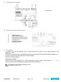
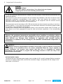
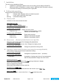
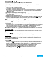
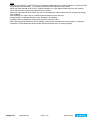
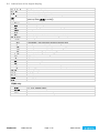
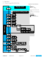
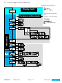
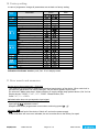
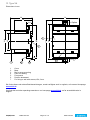
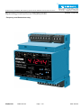
Temperature Relays and MINIKA®, Mains Monitoring, Digital Panelmeters MINIPAN®, Switching Relays and Controls Operating Instructions FR(MU)1000 ZIEHL industrie – elektronik GmbH + Co KG Daimlerstraße 13, D – 74523 Schwäbisch Hall + 49 791 504-0, [email protected], www.ziehl.de updated: 121024 Sc - Frequency- and Revolutions relay FR(MU)1000 12460-0701-03 Page 1 / 15 www.ziehl.de Table of contents 1 Application and short description ......................................................................................................... 3 2 Overview of functions ............................................................................................................................ 3 3 Connecting diagram ............................................................................................................................... 4 4 Display and operation parts................................................................................................................... 4 5 Programs................................................................................................................................................. 4 6 Important Information ............................................................................................................................ 5 7 Installation .............................................................................................................................................. 6 8 Putting into operation ............................................................................................................................ 6 9 8.1 Display mode ................................................................................................................................. 6 8.2 Menu mode (Decimal point behind the last digit ON) ..................................................................... 6 8.3 Parameter setting mode (Decimal point behind the last digit BLINKS) ........................................... 6 8.4 Indications of the digital display ..................................................................................................... 9 Operation .............................................................................................................................................. 10 9.1 Program 1: Pr1 / Speed Monitoring ............................................................................................. 10 9.2 Program 2: Pr2 / Frequency Monitoring ....................................................................................... 11 10 Factory setting ...................................................................................................................................... 12 11 Error search and measures ................................................................................................................. 12 12 Technical data ...................................................................................................................................... 13 13 Type V4 ................................................................................................................................................. 15 FR(MU)1000 12460-0701-03 Page 2 / 15 www.ziehl.de 1 Application and short description The FR(MU)1000 is a speed-monitor, a frequency-monitor and a measuring-transducer (FRMU only) in one device. 2 limits with 1 relay each can be programmed for under- or overspeed or under- or over-frequency or each monitoring a range (window min/max). The input for monitoring of speed can evaluate signals from proximity-sensors 2- or 3-wire, npn or pnp. The display can be scaled. Thus the real speed of a shaft can be displayed, even though there are several pulses per revolution, e.g. from a cogwheel. Application as Frequency-Relay: Monitoring of frequencies in mains 16 2/3 to 400 Hz on maintaining a range (min/max). Measuring input voltage (f-in) - AC 80...440 V / AC 20…200 V (Order-number U226134 + U226135) - AC 210...830 V / AC 110…300 V (Order-number U226138) Application as Speed-Relay: Monitoring of overspeed or underspeed, each with pre-alarm and alarm, monitoring of maintaining a range (min/max) or monitoring of stop at machines and equipment, e.g. at conveyors, escalators or lifts or for monitoring drive-belts. Applications as Measuring Transducer: (FRMU only) In addition the FRMU1000 can be used as a measuring-transducer to convert the input-signal into a standard-signal 0/4-20 mA or 0-10 V. 2 Overview of functions General: Setting in Hz or 1/min 5-digit display 2 limits / 2 relays Programmable for each relay: - monitoring of min.-, max.- or window - hysteresis - autoreset or reclosing lock - delay-time for switching and switching back down to 50 ms - operating- or closed-current-mode LEDs for state of relay and unit (Hz or 1/min) Storage of min- und max-values of the inputs Easy setting with 3 buttons Enable-input (E1-E2 closed = monitoring not active / open = monitoring active) Code lock against manipulation of settings Universal power supply unit AC/DC 24...240 V Terminals pluggable Analog output DC 0/4-20 mA or DC 0-10 V, freely scaleable (with isolation to frequency-input “f – in”), FRMU only Frequency: Measuring input voltage - AC 80...440 V / AC 20…200 V (Order-number U226134 + U226135) - AC 210...830 V / AC 110…300 V (Order-number U226138) Measuring-input for ZIEHL frequency-sensor STWA 1 FFH Monitoring of frequency of own supply-voltage Monitoring range 10...500 Hz Resolution of display 0,01 Hz Speed: Monitoring range 5...99999 1/min Display can be scaled Measuring input for proximity switch, 2- or 3-conductor, PNP or NPN Start-up-delay programmable Enable-input (E1-E2 closed = monitoring not active / open = monitoring active) FR(MU)1000 12460-0701-03 Page 3 / 15 www.ziehl.de 3 Connecting diagram 1) FRMU only 4 Display and operation parts 1 2 3 4 5 6 7 LEDs relay state Digital display, 5 digits LED speed measuring (1/min) LED frequency measuring (Hz) Pushbutton up Pushbutton set/reset Pushbutton down 5 Programs 2 programs (Pr) can be selected. Due to these Programs the device can be easily adapted to the application. Choose the Program fitting to your application and after that change the parameters! When changing the program all parameters are reseted upon "factory setting". (see chart " factory setting") Selecting the program: Keep the button "Set" pressed for 10 s when applying the supply voltage. Then program (Pr 1 ... Pr 2) can be choosen with the pushbuttons up/down and confirmed with set. Pr 1 = Revolutions control (factory setting) (1/min) Pr 2 = Frequency control (Hz) FR(MU)1000 12460-0701-03 Page 4 / 15 www.ziehl.de 6 Important Information DANGER! Hazardous voltage! Will cause death or serious injury. Turn off and lock out all power supplying this device before working on this device. To use the equipment flawless and safe, transport and store properly, install and start professionally and operate as directed. Only let persons work with the equipment who are familiar with installation, start and use and who have appropriate qualification corresponding to their function. They must observe the contents of the instructions manual, the information which are written on the equipment and the relevant security instructions for the setting up and the use of electrical units. The equipments are built according to DIN / EN and checked and leave the plant according to security in perfect condition. If, in any case the information in the instructions manual is not sufficient, please contact our company or the responsible representative. Instead of the industrial norms and regulations written in this instructions manual valid for Europe, you must observe out of their geographical scope the valid and relevant regulations of the corresponding country. Observe the maximum temperature permissible when installing in switching cabinet. Make sure sufficient space to other equipment or heat sources. If the cooling becomes more difficult e.g. through close proximity of apparatus with elevated surface temperature or hindrance of the cooling air, the tolerable environmental temperature is diminishing. Attention! When all relays are programmed in operation current mode (= pick up at alarm), a loss of the supply voltage or an instrument failure can remain unidentified. When the relay is applied as control instrument, the operator must ensure, that this error is recognized by regular examinations. We recommend to program and accordingly evaluate at least one relay in the closed-circuit current mode. ! Universal power supply The device has got a universal power supply, that is suitable for DC- and AC-voltages. Before connecting the device to supply-voltage make sure that the connected voltage corresponds with the voltage on the lateral type on the device. FR(MU)1000 12460-0701-03 Page 5 / 15 www.ziehl.de 7 Installation The unit can be installed as follows: Installation in switchgear cabinet on 35 mm mounting rail according to EN 60715 With screws M4 for installation on walls or panel. (additional latch included in delivery) Connection according to connection plan or type plate. 8 Putting into operation Decimal point behind the last digit: Off = display mode, displays values of measuring inputs On = menu mode, select the menu items blinking = parameter setting mode 8.1 Display mode Indication of the current measured value LEDs Relay (K1, K2) ON = relay picked up LED Speed (1/min) / Frequency (Hz) ON = according program selected Function button UP/DOWN Push short change into menu mode Push for > 2 s display of the stored MIN- or MAXvalues of the choosen input Function button SET/RESET Push for 2 s Reset restart interlock Push for 4 s display of the choosen program Push for 10 s display of the software version 8.2 Menu mode (Decimal point behind the last digit ON) Selection of the menu items for changing the parameters. Function button UP/DOWN Push short Selection of menu item; Change into display mode Function button SET/RESET Push short Change into parameter setting mode 8.3 Parameter setting mode (Decimal point behind the last digit BLINKS) LEDs indicate relays concerned by the parameter setting. Function button UP/DOWN Press short/long Changement of parameter value (slow/fast) Function button SET/RESET Press short Acceptation of setting and choice of next parameters, after the last parameter change into menu mode Selecting the inputs (Inpvt): Choose menu item with up/down until InpVt and type alternate in display. Here it can be read, which input is selected. Enter in programming with Set. Select input with up/down and store with Set. Multiplier/divisor (Mvlt / div) : The indicated or limit value is calculated from the formula: input * Mvlt / div Mean value (SvM): Valid measured value = mean value from 1...8 (SvM) measuring cycles. FR(MU)1000 12460-0701-03 Page 6 / 15 www.ziehl.de Setting the alarms (AL 1 / AL 2): Choose menu item with up/down until AL 1 and limit (limit value) alternate. Here it can be read clearly which limit value is programmed. Begin to program with set. Set limit with up/down and store with set. At window monitoring, this value is the lower limit of the window. Choose function: off Alarm OFF, relay is released all the time •:∆ Overspeed / overfrequency without reclosing lock •:: Overspeed / overfrequency with reclosing lock. Reset only possible after signal is below the limit (with hysterisis) and after the switchback-delay. The switchback-delay is indicated with blinking „A12L“ in the display. w_r Underspeed / underfrequency without reclosing lock w__ Underspeed / underfrequency with reclosing lock. Reset only possible after signal is below the limit (with hysterisis) and after the switchback-delay. The switchback-delay is indicated with blinking „A12L“ in the display.. ™«k Window monitoring without reclosing lock. ™«« Window monitoring with reclosing lock. Reset only possible after signal is within the window (with hysterisis) and after the switchback-delay. The switchback-delay is indicated with „A12L“ in the display. ALHi upper limit at window monitoring. Lower limit = AL 1 set limit. Set Hysteresis Alarm delay time dAL: An alarm is suppressed for this time, short-time exceeding of the limits does not cause an alarm. Switch-back delay doF: Alarms are switched off this time after the signal has returned into good-state. Function of relay: r-Closed-current circuit mode. Relay is picked up in GOOD and releases when the limit is exceeded = alarm. Advantage: errors and faults normally cause an alarm. Disadvantage: alarm also when supply-voltage is switched off and after switching on until the relay has picked up. A- Operating-current mode: relay is released in GOOD state and picks up when the limit is exceeded. No alarm at errors and when supply-voltage is switched off. Start-up-delay (dEnab): Monitoring starts this time after switching on the supply-voltage and after opening the enable -input E1E2. Display delay (ddisp): Defines the rate for updating the display. Set to higher values at nervous display. Simulation (Si): Here a measured input signal can be simulated with the buttons up/down. All functions of the device work as if this value was at the input. If no button is pressed for 15 minutes the device automatically switches back into the display mode. Code-lock (CodE): After setting all parameters they can be protected by activating the code lock. After pushing Set, the display indicates Pin. Adjust with buttons up/down Pin 00504 (factory setting). After pushing Set, code lock can be activated or switched off. After pushing Set again, an individual Pin can be selected (write down). When code lock is activated all parameters can be seen but not be changed anymore. In case of problems with the code lock (forgotten Pin) the lock can be switched off and the Pin can be set back to 00504, by pushing button set while connecting the device to supply-voltage until Cod / ofF is indicated in the display. FR(MU)1000 12460-0701-03 Page 7 / 15 www.ziehl.de Tips: - With the pre-setting Pr1 and Pr2 the most important parameters can be set in advance, so that only little modifications are necessary , e.g. setting of the limits (limit values) for each alarm. - When the right decimal point in the 7 segment display is on, the display mode has been left, and the menu items can be chosen with up/down (menu mode). - When the right decimal point blinks, you are in the parameter setting mode and can change the setting with up/down. - After finishing one menu item it is switched automatically on the next one. - Long pushing on up/down speeds up the changes in the display. - Pushing button up and down at the same time sets values to zero. - With reset (press Set/Reset for 2s) the display mode can be reached from every position (exception: simulation) of the parameter setting mode (the last selected value in is being stored). FR(MU)1000 12460-0701-03 Page 8 / 15 www.ziehl.de 8.4 Indications of the digital display Pr 1 / Pr 2 A1 , A2 A12 +L Inpvt U1-U2 npn pnp mvlt div Svm AL 1, AL 2 Fvnc off •:∆ •:: w_r w__ ™«k ™«« alhi H dal doF rEl r A denab ddisp on, oFF Si CodE Pin program number alarm 1 , alarm 2 active alarm 1 and alarm 2 active alarm locked (locked), „reset“ is necessary. remaining time until monitoring is activated (start-up-delay dEnab is ending) input frequency input (f - in) three wire proximity-switch NPN three wire proxy-switch PNP or two wire proxy-switch multiplier divisor mean value alarm limit (lower limit when monitoring a window) alarm function alarm off overspeed / over frequency without reclosing lock overspeed / over frequency with reclosing lock. underspeed / under frequency without reclosing lock underspeed / under frequency with reclosing lock window monitoring without reclosing lock window monitoring with reclosing lock upper limit when monitoring a window hysterisis switching-delay switch-back-delay function of relay closed-current mode, contacts 11-12 resp. 21-22 close at an alarm operating-current mode, contacts 11-14 (21-24) close at an alarm start-up-delay display delay on/off simulation code (pin) ex works 00504 FRMU only: ovt 0-10 0/4-20 ____ ,,,, analog output 0...10 V voltage output 0/4...20 mA current output value for 0 V, 0/4 mA at the output value for 10 V, 20 mA at the output DEn FR(MU)1000 12460-0701-03 Page 9 / 15 www.ziehl.de 9 Operation 9.1 Program 1: Pr1 / Speed Monitoring Operation with pushbuttons: Up Set Display mode 2 s = Max Reset = >2s Set Down Display 2 s = Min Up/down at same time sets values on zero. Parameter setting mode U1-U2 nPn pnp Inpvt Typ mvlt Value 00001 00250 Value 00001 00250 Value 00001 00008 Limit 00005 ...99999 div Svm error messages: Er 9 = device error Err = general error EEE = superordinated range fvnc off •:± •:: w_r w__ Menu mode AL 1 ™«k ™«« alHi Limit denab 000.05 ..099.99 s doF 00001 ...10000 000.05 ..099.99 s rEL r A .... Value 0000.0 ...0060.0 s Value 0000.1 ...0002.0 s ddisp H 00005 ...99999 dAL AL 2 Code-reset = 2 s set while switching in. (Pin = 00504) oFF FRMU only ovt Typ 0-10 0-20 4-20 ____ 00000 ...99999 Zero 00000 ...99999 Fullscale 00000 ...99999 Si CodE ,,,, on / oFF Pin 00000 ...09999 o.k. on oFF Pin 00000 ...09999 3x on / oFF 3x Err FR(MU)1000 12460-0701-03 Page 10 / 15 www.ziehl.de 9.2 Program 2: Pr2 / Frequency Monitoring Operation with pushbuttons: Up Display mode 2 s = Max Set Reset = >2s Set Down Display 2 s = Min Up/down on same time sets values on zero. Parameter setting mode Typ U1-U2 nPn pnp 1...8 00001 00008 Limit 010.00 ...500.00 Inpvt Svm AL 1 error messages: Er 9 = device error Err = general error EEE = superordinated range fvnc off •:± •:: w_r w__ ™«k ™«« alHi Menu mode Limit denab 000.05 ..099.99 s doF 000.10 ...010.00 000.05 ..099.99 s rEL r A .... Value 0000.0 ...0060.0 s Value 0000.1 ...0002.0 s ddisp H 010.00 ...500.00 dAL AL 2 Code-reset = 2 s set while switching in. (Pin = 00504) oFF FRMU only ovt Typ 0-10 0-20 4-20 ____ 000.00 ...500.00 000.00 ...500.00 Fullscale Zero 010.00 ...500.00 Si CodE ,,,, on / oFF Pin 00000 ...09999 o.k. on oFF Pin 00000 ...09999 3x Err FR(MU)1000 12460-0701-03 3x on / oFF Page 11 / 15 www.ziehl.de 10 Factory setting In case of programme change all parameters are set back on factory setting. Menuitem Inpvt mvlt div svm Alarm 1 AL 1 Alarm 2 AL 2 denab ddisp ovt (nur FRMU) Code Parameter Input type Multiplier Divisor Mean value Limit 1 (lower window limit) Fvnc (Function) alHi (upper window limit) H (Hysterisis) dAL (Alarm-delay) dof (Switch-back delay) rel (Relais function) Limit 2 (lower window limit) Fvnc (Function) alHi (upper window limit) H (Hysterisis) dAL (Alarm-delay) dof (Switch-back delay) rel (Relais function) Start-up-delay Display delay Type ____ (Zero) ,,,, (Fullscale) on / oFF Pin Value Pr 1 PnP 1 1 4 500 w_r 10 0Z50 0Z50 r 5000 •:∆ 100 0Z50 0Z50 r 2Z0 0Z5 0-10 0 5000 off 00504 My data Pr 2 U1-U2 4 48Z00 ™«k 52Z00 1Z00 0Z10 0Z10 r 47Z00 ™«k 53Z00 1Z00 0Z10 0Z10 r 0Z1 0Z5 0-10 0.00 100Z00 off 00504 Indication of software version: push „Set“ 10 s in display mode. 11 Error search and measures Device cannot be programmed – Code lock The code lock gives protection against unauthorized manipulation of the device. When code lock is activated the parameters can not be changed. The pin can be typed in by the user. Pin unknown? Make code-reset: When switching in supply-voltage keep pushed button „Set“ for 2 s. Display shows: "88888"; "CodE"; "oFF"; "88888" release button „Set“. Code = oFF, Pin = 00504. Indicated value does not correspond to input signal Correct program chosen? Input type (Inpvt) selected correct? Multiplier and divisor programmed correct when monitoring speed (PR 1)? Indication „Er9“ Er9 is an internal fault of the device. Switch off- and on the power-supply. If after that there still is an error indicated, the unit must be sent to the factory for repair. FR(MU)1000 12460-0701-03 Page 12 / 15 www.ziehl.de 12 Technical data Rated supply voltage Us: Tolerance Frequency Input AC/DC 24 – 240 V DC 20,4 - 297 V AC 20 - 264 V 0, 40...500 Hz, from AC 80 V: 10...500 Hz < 3 W < 10 VA Relay-output: Switching voltage Switching current Switching power 2 x 1 Changer (CO) max. AC 400 V max. 5 A max. 1250 VA (ohm resistive load) max. 48 W at DC 24 V Nominal operating current Ie: AC15 DC13 Recommended fuse Contact life mechanic Contact life electrical. Test conditions Rated impulse voltage - measuring input f-in Contamination level Rated insulation voltage Ui - measuring input f-in On-time Permitted ambient air temperature Interference resistance Interference transmission Vibration resistance EN 60068-2-6 FR(MU)1000 12460-0701-03 Ie = 1,25 A Ue = 400 V Ie = 2 A Ue = 250 V Ie = 2 A Ue = 24 V T 3,15 A (gL) 15 x 106 Switching cycles 2 x 10⁵ Switching cycles at AC 250 V / 3 A 5 x 10⁵ Switching cycles at AC 250 V / 2 A 1 x 10⁵ Switching cycles at AC 250 V / 0,8 A EN 60255 / EN 60947 4000 V 4000 V -> Order-number U226134 + U226135 6000 V -> Order-number U226138 2 300 V 300 V -> Order-number U226134 + U226135 600 V -> Order-number U226138 100 % -20 °C ... +60 °C EN 60068-2-2 dry heat EN 61000-6-2 EN 61000-6-3 2…25 Hz ±1,6 mm 25 ... 150 Hz 5 g Page 13 / 15 www.ziehl.de Measuring inputs f-in -> Order-number U226134 + U226135 f-in -> Order-number U226138 Three wire - PNP Three wire - NPN Two wire- proximity switch Switching frequency Cable length for proximity switch Resistance of line Capacity of line e.g. max. length of cable Measuring error Temperature factor Measuring time Auxiliary supply +18 V 20 mA Frequency 10,00 ... 500,00 Hz admissible voltage AC 20...200 V admissible voltage AC 80...440 V Frequency 10,00 ... 500,00 Hz admissible voltage AC 110...300 V admissible voltage AC 210...830 V UMax 28 V; switching threshold approx. 10 V 18 V / 3,5 mA; switching threshold approx. 9 V 18 V / 3,5 mA ( 24 V DC ) Switching threshold approx. 1,5 mA max. 1,6 kHz; 99999 1/min PNP, NPN, 2-wire ≤ 10 Ω / line ≤ 22 nF 0…800Hz; ≤ 10 nF 800...1600 Hz < 150 m with cable LIFYY11Y 3*0,34 mm at 0…800Hz ± 0,05 % of measured value ± 1 Digit < 0,002 %/K 1 Period * Svm (number mean values) >= 3 Periods; after placing the measuring signal 16 ... 21 V max. 20 mA Enable E1-E2 18 V / 3 mA Switching threshold approx. 9 V Analogue output: (FRMU only) Voltage output 0...10 V Temperature factor Current output 0/4...20 mA Temperature factor Error from burden electrically insulated to input f - in (U1-U2) max. 10 mA error <0,1 % of full scale < 0,01 %/K max. 500 Ω error <0,15 % of full scale < 0,015 %/K (250 Ω - resistance)/250 Ω * 0,15 % of final value Housing Mounting height Width Dimensions Line connection solid wire Stranded wire with insulated ferrules Torque Protection class housing Protection class terminals Fitting position Mounting type V 4 55 mm 4 TE (W x H x D) 70 x 90 x 58 mm each 1 x 1,5 mm2 each 1 x 1,0 mm2 0.5 Nm (3,6 lb.in) IP 30 IP 20 any Snap mounting on 35 mm standard rail EN 60 715 or M4 screws app. 180g Weight Subject to technical changes FR(MU)1000 12460-0701-03 Page 14 / 15 www.ziehl.de 13 Type V4 Dimensions in mm 58 70 48 Option 16,5 98 116 (90) 45 4 3 61,8 5 7 6 1 1 2 3 4 5 6 7 2 3 Cover Base Bar for snap mounting Latch for sealing Front panel Position downward For fixing to wall with screws, Ø 4,2 mm. Sie finden diese und weitere Betriebsanleitungen, soweit verfügbar auch in englisch, auf unserer Homepage www.ziehl.de. You find this and other operating-manuals on our homepage www.ziehl.de, as far as available also in English. FR(MU)1000 12460-0701-03 Page 15 / 15 www.ziehl.de