1
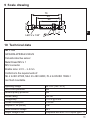
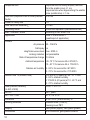
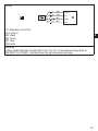
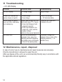
Original operating instructions Fail-safe inductive sensor UK 704197 / 01 05 / 2010 GF711S Contents 1 Preliminary note���������������������������������������������������������������������������������������������������3 1.1 Explanation of symbols����������������������������������������������������������������������������������3 2 Safety instructions�����������������������������������������������������������������������������������������������4 2.1 Safety-related requirements regarding the application����������������������������������4 3 Items supplied�����������������������������������������������������������������������������������������������������5 4 Functions and features����������������������������������������������������������������������������������������5 5 Functions�������������������������������������������������������������������������������������������������������������6 5.1 Enable zone���������������������������������������������������������������������������������������������������6 6 Installation�����������������������������������������������������������������������������������������������������������7 7 Electrical connection��������������������������������������������������������������������������������������������8 7.1 Operation as 4-wire unit��������������������������������������������������������������������������������8 7.2 Operation as 3-wire unit��������������������������������������������������������������������������������8 8 Operation�������������������������������������������������������������������������������������������������������������9 8.1 Switching status of the outputs����������������������������������������������������������������������9 8.1.1 The safe state���������������������������������������������������������������������������������������9 8.1.2 The switched state��������������������������������������������������������������������������������9 8.1.3 Output data�������������������������������������������������������������������������������������������9 8.1.4 Cross faults�������������������������������������������������������������������������������������������9 8.2 Response times�������������������������������������������������������������������������������������������10 8.3 LED display�������������������������������������������������������������������������������������������������10 9 Scale drawing���������������������������������������������������������������������������������������������������� 11 10 Technical data�������������������������������������������������������������������������������������������������� 11 11 Troubleshooting�����������������������������������������������������������������������������������������������14 12 Maintenance, repair, disposal��������������������������������������������������������������������������14 13 Approvals/standards����������������������������������������������������������������������������������������15 14 Terms and abbreviations����������������������������������������������������������������������������������15 2 1 Preliminary note The instructions are part of the unit. They are intended for authorised persons according to the EMC and Low Voltage Directive and safety regulations. The instructions contain information about the correct handling of the product. Read the instructions before use to familiarise yourself with operating conditions, installation and operation. Adhere to the safety instructions. 1.1 Explanation of symbols UK ► Request for action LED on LED off LED flashes LED flashes quickly Important note 3 2 Safety instructions • Follow the operating instructions. • Improper use may result in malfunctions of the unit. This can lead to personal injury and/or damage to property during operation of the machine. For this reason note all remarks on installation and handling given in these instructions. Also adhere to the safety instructions for the operation of the whole installation. • In case of non-observance of notes or standards, specially when tampering with and/or modifying the unit, any liability and warranty is excluded. • The unit must be installed, connected and put into operation by a qualified electrician trained in safety technology. • The applicable technical standards for the corresponding application must be complied with. • For installation the requirements according to EN 60204 must be observed. • In case of malfunction of the unit please contact the manufacturer. Tampering with the unit is not allowed. • Disconnect the unit externally before handling it. Also disconnect any independently supplied relay load circuits. • After setup the system has to be subjected to a complete function check. • Use the unit only in specified environmental conditions (→ 10 Technical data). In case of special operating conditions please contact the manufacturer. • Use only as described below (→ 4). 2.1 Safety-related requirements regarding the application It must be ensured that the safety requirements of the respective application correspond to the requirements stated in these instructions. Observe the following requirements: ►► Take measures to avoid metallic objects being placed on the sensing face intentionally or unintentionally. ►► Adhere to EN 1088 for interlocking devices associated with guards. ►► Adhere to the specified operating conditions (→ 10 Technical data). Use of the sensor in the vicinity of chemical and biological media as well as ionising radiation is not permitted. 4 ►► Adhere to the principle of normally closed operation for all external safety circuits connected to the system. ►► In case of faults within the fail-safe sensor which result in the defined safe state: take measures to maintain the safe state when the complete control system continues to be operated. ►► Replace damaged units. 3 Items supplied 1 fail-safe sensor GF711S with 2 mounting nuts M12, UK 1 operating instructions GF711S, ident no. 704197. If one of the above-mentioned components is missing or damaged, please contact one of the ifm branch offices. 4 Functions and features The fail-safe inductive sensor GF711S detects metal without contact. Safety function SF: The safe state (output stage switched off; logic "0") is achieved when undamping greater than or equal to the safe switch-off distance sar (→ 10 Technical data). Also observe the notes on installation of the sensor (→ 6 Installation). The fail-safe sensor conforms to Performance Level d to EN ISO 13849-1 as well as the requirements SIL 2 to IEC 61508 and fulfils SILcl 2 to IEC 62061. The unit corresponds to the classification I2A12SP2 to IEC 60947-5-2 for non flush installation (→ 6 Installation). The fail-safe inductive sensor has been certified by TÜVNord. 5 5 Functions fail-safe sensor close zone enable zone safe switch-off distance sar damping element Yellow signal LED: switching status Green power LED: operating voltage 5.1 Enable zone The outputs (OSSD) are only enabled when a damping target is present in the enable zone. Outside this enable zone the outputs remain switched off. If damped with a standard target plate of 12 x 12 x 1 mm made of FE360 (= mild steel) and non flush installation to EN 60947-5-2 the enable zone is in the range of ≤ 0,5 ... ≥ 4 mm. The safe switch-off distance sar is > 6 mm. The enable zone is different if damping elements which deviate from the standard target plate in terms of material, form and size are used. Enable zone for other materials*: Material stainless steel AIMg3G22 CuZn37 Cu Enable zone 0...3.1 mm 0...1.8 mm 0...2.0 mm 0...1.2 mm * Typical values for damping with a reference target plate of 12 x 12 x 1 mm and non flush installation to IEC 60947-5-2 at an ambient temperature of 20°C. 6 Depending on the characteristics of the damping element there may be no close zone. 6 Installation The unit can be non flush mounted according to IEC 60947-5-2, type I2A12SP2. ►► Ensure the unit cannot work loose. Maximum tightening torque: 20 Nm ►► Adhere to the installation conditions in accordance with the figures 1 to 3: UK Flush installation of the fail-safe sensor is not permitted since this can result in an increase of the sensing range up to the enabling of the outputs (OSSDs). 7 7 Electrical connection ►► Disconnect power. Also disconnect any independently supplied relay load circuits. ►► Supply voltage: connect L+ to pin 1 and L- to pin 3 of the connector. The nominal voltage is 24 V DC. This voltage may vary between 19.2 V and 30 V incl. 5% residual ripple to EN 61131-2. In case of a single fault the supply voltage must not exceed a maximum of 40 V DC. (This requires the safe separation between power supply and transformer). For unit with cULus approval and the scope of validity cULus: The device shall be supplied from an isolating transformer having a secondary listed fuse rated either a) max. 5 amps for voltages 0~20 Vrms (0~28.3 Vp) or b) 100/Vp for voltages of 20~30 Vrms (28.3~42.4 Vp). 7.1 Operation as 4-wire unit Safety-related logic unit 7.2 Operation as 3-wire unit Safety-related logic unit 8 In case of operation as 3-wire unit only A2 must be used as output (OSSD). Otherwise the safety function of the sensor will be impaired or prevented. ►► Connect output A1 to supply voltage. ►► Make absolutely sure to exclude cross faults and short circuits between the supply voltage and output A2 by means of appropriate installation! The indicated values regarding the safety function (→ 10 Technical data) remain unchanged. UK 8 Operation 8.1 Switching status of the outputs 8.1.1 The safe state The safe state is when at least one of the outputs A1 and A2 (OSSD) is switched off (zero-current state: logic "0"). If one of the outputs A1 and A2 is switched off, the subsequent safety-related logic unit must bring the complete system into the state defined as safe. 8.1.2 The switched state If the damping element is in the enable zone and if there is no sensor error, both outputs A1 and A2 (OSSD) are enabled (logic "1"). 8.1.3 Output data The output data are based on the input data to EN 61131-2 type 1 or 2: logic "1" logic "0" ≥ 15 V ≥ 11 V ≤5V 2...15 mA 15...30 mA leakage current 0.2 mA 8.1.4 Cross faults • A cross fault between both outputs (A1 and A2) is detected by the fail-safe sensor and leads to switching off the outputs (OSSD) at the next safety request. The outputs A1 and A2 remain switched off until the error has been removed. • A cross fault between one of the two outputs (A1 or A2) and the supply voltage leads to switching off the other output (A2 or A1) in case of a safety request. 9 8.2 Response times Response time on safety request (removal from the enable zone) Response time when approaching the enable zone (enable time) Risk time / response time for safety-related faults Simultaneity of switching on and off of the outputs in case of a safety request Duration of switch-off test pulses ≤ 1 ms ≤ 1 ms ≤ 20 ms ≤ 1 ms ≤ 1 ms 8.3 LED display LED status Operating status Outputs Signal Power no voltage supply both outputs switched off Signal Power undervoltage Signal Power overvoltage Signal Power Signal Power Signal Power 10 A1 A2 (OSSD) (OSSD) 0 0 1 0 0 0 both outputs switched off 0 0 damping element at safe switch-off distance from the sensor (≥ 6 mm) sensor error (→ 11 Troubleshooting) both outputs switched off 0 0 one output or both outputs switched off damping element in the enable zone both outputs enabled 0 1 0 1 1 0 0 1 damping element in the close zone output A2 is switched off 1 0 9 Scale drawing UK 10 Technical data GF711S GIFA4004-2PS/SIL2/V4A/US Fail-safe inductive sensor Metal thread M12 x 1 M12 connector Enable zone: ≤ 0.5 ... ≥ 4 mm Conforms to the requirements of: SIL 2 to IEC 61508, SILcl 2 to IEC 62061, PL d to EN ISO 13849-1 non flush mountable Operating voltage Short-circuit protection Reverse polarity protection Current rating Voltage drop Current consumption Outputs A1, A2 (OSSD) Rated insulation voltage Output voltage at 24V 24 V DC (19.2...30 V) yes yes 100 mA < 2.5 V @ 30 mA < 20 mA PNP 30 V compatible with EN 61131-2 inputs type 1, 2 11 Response time Risk time (response time for safety-related faults) Power-on delay time Safe switch-off distance sar Operating mode EMC / vibration, shock Application response time on safety request (removal from the enable zone) ≤ 1 ms response time when approaching the enable zone (enable time): ≤ 1 ms ≤ 20 ms 1s > 6 mm continuous operation (maintenance-free) according to IEC 60947-5-2 class C to EN 60654-1 (weatherproof application) Climate Air pressure Salt spray Height above sea level Ionising radiation Rate of temperature change Ambient temperature 80...106 kPa no max. 2000 m not permissible 0,5 K/min -25..70 °C for service life ≤ 87 600 h 10...40 °C for service life ≤ 175 200 h Relative air humidity 5...95 % for service life ≤ 87 600 h 5...70 % for service life ≤ 175 200 h Mission time TM (mission time) Safety-related reliability (to IEC 61508) MTTFD DC / CCF / Cat. Protection Housing materials Display Connection 12 ≤ 87 600 h (10 years) at -25...70 °C and 5...95 % relative humidity ≤ 175 200 h (20 years) at 10...40 °C and 5...70 % relative humidity PFH < 1 x 10⁻⁷/ h 2011 years 87 % / 70 % / 2 IP 65 / IP 67 (to EN 60529), III stainless steel (316S12), housing cover PBT LED yellow (signal); LED green (power) M12 connector, gold-plated contacts Wiring Evaluation unit or PLC Core colours: BK: black BN: brown BU: blue WH:white Remarks: Unless stated otherwise, all data refer to the 12 x 12 x 1 mm reference target plate to IEC 60947-5-2 (FE360 = mild steel) over the whole temperature range. UK 13 11 Troubleshooting → 8.3 LED-Display Problem Possible cause Troubleshooting No LED display No voltage supply Apply voltage Power LED flashes and sensor does not switch •Undervoltage •Overvoltage Correct the voltage (→ 10 Technical data) Sensor does not switch, even not after undamping and redamping Sensor was brought into the safe state (logic "0"). Cause: •Cross fault between both outputs A1 and A2 •Cross fault between one output (A1 or A2) and the supply voltage •Error in the sensor detected Due to its characteristics (material, form, size), the damping element displaces the enable zone until directly in front of the sensing face •Remove the cross fault •Replace the unit No close zone If possible, change the material, form or size of the damping element (→ 5.1 Enable zone) 12 Maintenance, repair, disposal In case of correct use no maintenance and repair measures are necessary. Only the manufacturer is allowed to repair the unit. After use dispose of the unit in an environmentally friendly way in accordance with the applicable national regulations. 14 13 Approvals/standards The following standards and directives have been applied: • 2006/42/EC European machinery directive • 2004/108/EC EMC directive • EN ISO 13849-1 PL d (2006) Safety of machinery - Safety-related parts of control systems • IEC 60947-5-2 (2008) low voltage switchgear and controlgear: control circuit devices and switching elements - proximity switches • IEC 61508 (2000) • IEC 62061 (2005) • UL 508 UK 14 Terms and abbreviations CCF Common Cause Failure DC Diagnostic Coverage MTTFD Mean Time To Dangerous Failure OSSD Output Signal Switching Device PFH Probability of failure per Hour PL Performance Level PL to EN ISO 13849-1 SIL Safety Integrity Level SILcl Safety Integrity LevelClaim Limit SIL 1-4 to IEC 61508. The higher the SIL, the lower the probability that a safety function will fail. to IEC 62061 TM Mission Time Lifetime (= max. service life) 15