1
FAS
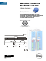
FREQUENCY INVERTER
POSIDRIVE® FAS 4000
Posi-Upgrade
> Posi-Upgrade <
Operating instructions
It is essential to read and comply with these
instructions and the Installation and Commissioning
Instructions (publication no. 441581) prior to
installation and commissioning.
MANAGEMENTSYSTEM
certified by DQS according to
DIN EN ISO 9001, DIN EN ISO 14001
Reg-No. 000780 UM/QM
SV. 4.5
02/2004
POSIDRIVE® FAS 4000 / Posi-Upgrade
STÖBER
ANTRIEBSTECHNIK
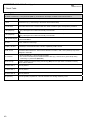
Table of Contents
Table of Contents
1.
Notes on Safety
1
5.
Parameter Description
12
2.
Posi-Upgrade
2
6.
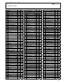
Parameter Table
37
3.
Vergleich FAS mit FDS
3
7.
Result Table
40
4.
Positioning Control
4.1 Function Overview
4.2 Connections
4.3 Destination Pos. and Proc. Blocks
4.4 Absolute/Relative Positioning
4.5 Commissioning
4.5.1 Limited Traversing Range
4.5.2 Cont. Trav. Range (Rotary Axis)
4.6 Reference Point Traversing
4.7 Position Controller
4.8 Process Block Chaining
4.9 Simple Examples
4.10 Emergency Off
4.11 Posi Switching Points
4
4
4
5
5
6
6
6
7
8
8
9
10
10
8.
Operating States
41
9.
Faults/Events
42
STÖBER ANTRIEBSTECHNIK Germany
44
STÖBER ANTRIEBSTECHNIK International 46
POSIDRIVE® FAS 4000 / Posi-Upgrade
STÖBER
ANTRIEBSTECHNIK
1. Notes on Safety
1
NOTES ON SAFETY
To prevent avoidable problems from occurring during commissioning and/or operation, it is essential to
read and comply with this entire instruction manual before starting installation and commissioning.
Based on DIN EN 50178 (once VDE 0160), FAS-series frequency inverters are defined as electronic power
equipment (BLE) for the control of power flow in high-voltage systems. They are designed exclusively to power
three-phase-current, asynchronous machines. Handling, installation, operation and maintenance must be
performed in accordance with valid and/or legal regulations, applicable standards and this technical
documentation.
The frequency inverter are products of the restricted sales class (in accordance with IEC 61800-3). Use of this
products in residential areas may cause high-frequency interference in which case the user may be ordered to
take suitable measures.
The user must ensure strict adherence to these standards.
The safety notes and specifications stated in additional sections (items) must be adhered to by the user.
Caution! High touch voltage! Danger of electric shock! Danger of death!
Never under any circumstances may the housing be left open or connections disconnected when the power is
on. Disconnect the power plug of the frequency inverter and wait at least 5 minutes after the power voltage has
been switched off before opening the frequency inverter to install or remove option boards. Correct configuration
and installation of the inverter drive are prerequisites to correct operation of the frequency inverter. Only
appropriately qualified personnel may transport, install, commission and operate this device.
Pay particular attention to the following:
• Permissible protection class: Protective ground; operation only permitted when protective
conductor is correctly connected. The devices may not be operated directly on IT networks.
• Installation work may only be performed in a voltage-free state. When work has to be done on the drive,
inhibit the enable and disconnect the complete drive from the power network. Adhere to the 5 safety
regulations.
• Discharge time of the DC link capacitors > 5 minutes
• Do not penetrate the interior of the device with any kind of object.
• When performing installation or other work in the switching cabinet, protect the device against falling
objects (e.g., pieces of wire, flexible leads, metal parts and so on). Conductive parts may cause short
circuiting or device failure on the frequency inverter.
• Before commissioning, remove all extra coverings to prevent the device from overheating.
The frequency inverter must be installed in a switching cabinet which does not exceed the maximum ambient
temperature (see technical data).
Only copper wiring may be used. For wire cross sections, see table 310-16 of standard NEC at 60° C or 75° C.
STÖBER ANTRIEBSTECHNIK accepts no liability for damages caused by non-adherence to the
instructions or applicable regulations.
The motor must have an integral temperature monitoring device or external motor overload protection must be
used.
Only suitable for use on power networks which cannot supply more than a symmetric, nominal short-circuit
current of 5000 A at 240 V ac / 480 V ac.
Notes:
Subject to technical changes for improvement of the devices without prior notice. This documentation
is solely a product description. It is not a promise of features in the sense of warranty rights.
1
POSIDRIVE® FAS 4000 / Posi-Upgrade
STÖBER
ANTRIEBSTECHNIK
2. Posi Upgrade
2
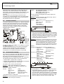
POSI UPGRADE
Execution of Posi Upgrade requires a special module (blue
housing). A code is downloaded to the inverter from this Posi
Upgrade module and stored non-volatilely in the
exchangeable Paramodule.
Customized to your needs
Depending on your requirements, a Posi Upgrade module with
positioning code for 10, 20, 50 or 100 inverters can be
delivered. Each time an upgrade is performed, the number of
possible positioning upgrades is decremented by one.
Transparency
The FDS Tool software (starting with version 4.5D) can be
used to read the contents of an upgrade module. Among
others, a serial number list is indicated with the devices
upgraded up to now and the number of positioning controller
upgrades which are still possible.
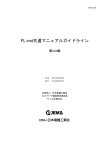
Handling
OFF
Turn off the power supply.
Plug in the Posi Upgrade
module.
ON
Turn on the power supply.
Wait until the green LED is
on continuously.
Disconnect Posi Upgrade
module. Æ Finished !
To your advantage
• Once performed, a Posi Upgrade is retained even when the
inverter is changed. It can be moved from one inverter to the
next with the red Paramodule. This means you don't need a
new upgrade each time you exchange a device.
• A red LED during an upgrade indicates a Posi Upgrade
module which is "used up." If you don't have a new Posi
Upgrade module handy, you can continue a once started
commissioning procedure as follows. Disconnect the Posi
Upgrade module and the positioning functionality remains
fully available until the next power off.
• Do something for the environment. STÖBER
Antriebstechnik will reload your completely used Posi
Upgrade module with the desired number of Posi Upgrades.
2
Possible errors
1. The green LED is flashing.
• The positioning controller was already upgraded. The
upgrade is stored non-volatilely on the plug-in
Paramodule.
• Since the Upgrade module was not inserted correctly, it
was not recognized.
• No Paramodule is installed.
• The last "A00 Save parameter" was interrupted when
FAS power was turned off too soon. Start A00 again and
let it run to the end.
• A Paramodule is installed whose data content does not fit
the current FAS software version. "A00 Save parameter"
must be executed once for adaptation. Then turn FAS
power supply OFF and ON again.
• Black Parabox (accessory for FDS 4000) is installed. The
black Parabox cannot be used with the FAS.
2. The red LED is on.
• The upgrade code has already been used up completely.
The position controller remains activated until the next
time the FAS power supply is turned off. FDS Tool can
be used to read the number of remaining Posi Upgrades
from the Upgrade module.
• The Upgrade module or the Paramodule was removed
during the upgrade. Repeat the procedure.
• The Upgrade module or the Paramodule is defective. It
must be returned to STÖBER Antriebstechnik for
replacement. The POSI Upgrade cannot be performed.
3. The FAS cannot be released. The red or green LED is
continuously on. The FAS will not start up until the Upgrade
Module is removed.
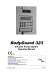
Reading an Upgrade Module with a PC
• Connect the Upgrade module to the serial interface (usually
port COM1).
• Start FDS Tool.
• Open the "data" menu.
• Click "read parabox."
• The screen which appears shows the remaining number of
Upgrades and a list of the device numbers of the already
upgraded inverters. See figure below.
POSIDRIVE® FAS 4000 / Posi-Upgrade
STÖBER
ANTRIEBSTECHNIK
3. Comparison of FAS and FDS
3
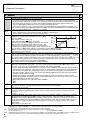
COMPARISON OF FAS AND FDS
For those who have already worked with FDS and are changing to FAS, the table below gives you an overview of the functional
differences.
FDS
FAS
Commentary
Two analog inputs
One analog output
One analog input
No analog output
F20 to F25 omitted
F40 to F43 omitted
Option boards
No option boards
- Limited number of digital inputs
- No evaluation of an absolute value encoder
- No wire break monitoring of the encoder
No technology functions
G.. and H.. parameters omitted
Internal auxiliary voltage for encoder
No extra power pack for encoder
Technology functions:
- Winding computer
- PID controller
- Electronic gear
External encoder power
supply
With its reduced functionality, FAS makes commissioning easier and quicker.
The FAS with Posi Upgrade is particularly suitable for:
• Very simple positioning tasks as an independent device
• Standard positioning tasks integrated in fieldbus environment
• Complex positioning tasks integrated in fieldbus environment
The serial interface gives the inverter flexibility. The USS protocol (developed by Siemens AG) handles communication via
RS 232. A Kommubox for the PROFIBUS-DP or CAN bus can be installed for integration on a fieldbus.
3
POSIDRIVE® FAS 4000 / Posi-Upgrade
STÖBER
ANTRIEBSTECHNIK
4. Positioning control
4
POSITIONING CONTROL
With the Posi-Upgrade, POSIDRIVE® FAS 4000 frequency
inverters offer integrated positioning control. A motor with a
built-on incremental encoder is the prerequisite for precise and
reproducible positioning. In "Vector Control" mode (B20=2),
the motor provides the characteristics of an asynchronous
servo drive.
Positioning can also be used without encoders in control mode
SLVC (SensorLess Vector Control).
4.1
•
•
•
•
•
•
•
•
•
•
•
•
•
•
•
•
•
•
Function overview
8 positions can be programmed as 8 process blocks.
Destination travel is precise to the increment.
Continuous position control with following error monitoring
Parameterization in units (e.g., degrees, mm)
Resumption of interrupted process blocks possible
Change in destination possible during traversing
Reference point travel with several modes
Sequence programming possible via process block chaining
(e.g., "Go to pos. 1, wait 2 sec, go on to pos. 2, wait for
signal and return")
Tip mode (inching)
Teach-In-Funktion.
Speed override via analog input possible
Any gear ratios are calculated with fractions without
rounding errors. No drifting with continuous axes.
Continuous referencing for continuous axes
"Electrical cam" function switches relay 2 within
programmed position range.
Hardware and software limit switch
Rotary attachment function
Path specification via analog input possible
Brake control for lifting systems
Feldbus
®
speed
override
POSIDRIVE
FAS 4000
2
W
s
ai
C , V,
el
PT U
R
M
3~
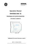
4.2
Connections – standard configuration
The standard device without option board is used for simple
applications.
Applications which require more binary inputs are
implemented with the fieldbus.
The analog input or the fieldbus can be used to adjust
positioning speed steplessly. Called "speed override," this
function is not only useful during commissioning but also for
tipping mode, changes in the number of pulses of a machine,
and so on.
4
The following functions for binary inputs (parameters F31 to
F34) are important:
• RV-select0 to 2: Binary coded position selection. Process
block 1 is selected with "000," and process block 8 is
selected with "111."
• 8:halt: Rising edge interrupts running motion with the
current process block ramp. Since tip mode (i.e., inching)
via binary inputs is not possible unless halt is active, halt
switches between tip and automatic operation.
• 9:quick stop: Rising edge interrupts positioning with
maximum acceleration I11.
• 16:posi.step: When a chain of process blocks is being
used, posi.step starts the consecutive process blocks. A
movement which is in progress is not interrupted (→ I40).
• 19:posi.start: Starts the just selected process block. A
movement which is in progress is always interrupted.
• 20:posi.next: Only for chained process blocks. If
programmed appropriately (cf. J17=3), immediately
concludes the running process block, and starts the next
one. A remaining path which is to be traveled after posi.next
occurs can be defined. See chapter 4.8.
• 17:tip+, 18:tip-: Tip mode (i.e., inching)
• 21:stop+, 22:stop-: Limit switch
• 23:reference input: Reference switch connection
• 24:start reference: Starts reference point traversing
• 25:teach-in: Actual position is assumed in the just selected
process block.
Ö The binary inputs can be inverted via F51 to F54. Removal
of the enable always causes a quick stop with maximum
acceleration I11.
Analog input AE1 (par. F25)
• 1:additional RV: Relative traversing paths are multiplied by
(100% + level). Example: 0 V → no additional reference
value (i.e., 100% of the traversing path).
• 4:RV-factor: Relative traversing paths are multiplied by the
level. Example: 0 V → no movement (i.e., 0% of the
traversing path).
• 5:override: The programmed positioning speed can be
changed online via potentiometer ("speed override" function
for CNC controllers), for example.
• 6:posi. offset: An offset can be added to the current
position online via AE1. Cf. parameter I70.
Relay outputs (par. F00 and F81)
• 3:Ref Val reached: Location in position window I22. Signal
appears when drive "in position."
• 8:electrical cam: Signal appears when the actual position
is located between parameters I60 and I61. Signal is used
as message to other modules, for example.
• 9:Following error: Signal appears when the maximum
following error in I21 is exceeded.
• 10:Position active: Drive is in position control waiting for
posi.start or posi.step. No process block and no process
block chain being processed.
• 13:referenced: Drive is referenced.
• 19:s-memory1 to 21:s-memory3: Output the memory
locations set by the posi switching points during processblock movements (see chap. 10.12).
• 23:RV-ackn.0 to 25:RV-ackn.2: Binary coded response
message from the active I82 process block. Cf. diagram in
chap. 4.3.
Ö A fieldbus also offers a simple and easy way to access
these signals. Status and control bits (E100 and E101) are
just two examples. For details, see documentation of the
fieldbus.
POSIDRIVE® FAS 4000 / Posi-Upgrade
STÖBER
ANTRIEBSTECHNIK
4. Positioning control
For fieldbus addressing:
Function BE1 to 5 (F31 to F35)
1: Reference value-select 0
2: Reference value-select 1
3: Reference value-select 2
4: Motorpoti up (with D90=1)
5: Motorpoti down (with D90=1)
6: Direction of rotation
7: Additional enable
8: Halt
9: Quick stop
10: Torque select
11: Parameter set-select
12: Extern fault
13: Fault reset
16: Posi.step
17: Tip +
18: Tip 19: Posi. start
20: Posi. next
21: Stop +
22: Stop 23: Reference input
24: Start reference
32: Brake release
Bit-No. in E101
8
9
10
14
15
13
6
0
1
7
5
2
3
17
21
22
16
18
24
25
26
20
23
Note: Functions which are controlled via the fieldbus may not
be defined in F31 to F35.
Function AE1 (F25)
1:
2:
3:
4:
5:
6:
8:
9:
10:
4.3
Additional reference value
Torque-limit
Power-limit
Reference value-factor
Override
Posi. offset
rotation field magnet moment
n-Max
Reference value
Bus
parameter
E104
E102
E103
E105
E106
E107
E109
E126
E119
Byte
2
2
2
2
2
4
2
2
2
Destination positions and process blocks
Each position to be approached to is described by several
parameters. Together these parameters make up a process
block. 8 process blocks are available. This permits 8 different
positions to be approached. Process block
no. 1 is described by parameters J10 to J18, while the second
process block is described by parameters J20 to J28, and so
on.
Proc. blk 8: J80 to J88
Proc. blk 2: J20 to J28
Proc. blk 1: J10 to J18
J10: Dest. position
J11: Relative/absolute
J12: Speed
J13: Acceleration
......
A process block can be selected as shown below.
• J02=1...8; The entered value corresponds to the particular
process block.
Entry of the value "0" permits selection of the process block
via "reference value-select" entry.
• Via "reference value-select" inputs;
With J02=0 the process block can be selected via the inputs
"reference value-select 0" to "ref. val. select 2". The binary
combination "000" selects process block no. 1; "111" selects
process block no. 8.
The response message of the current process block
appears:
• In parameter I82 ("active process block")
• In the 2nd line of the operational indication when
Controlbox is connected.
• Binary coded via fieldbus (status bits E100) „Bit 24: RVackn.0“ to „Bit 26: RV-ackn.2“. The selected process block
is shown inverted until the movement starts.
When a process block starts, the active block is not shown
inverted (binary-coded like RV-select signals) as long as
posi.start, posi.step or posi.next is queued.
When a process block cannot be started (e.g., see
"51:refused", chap. 9 Fault/Events), the selected block
continues to be shown inverted. This happens even when a
movement is terminated.
RV-ackn..=
/RV-select
Posi.start or posi.step=1:
RV-ackn..= active proc. blk
RV-ackn..=
/RV-select
Posi.start
RV-select 0
RV-ackn0
RV-select 1
RV-ackn1
In-position
Movement
Changed is
ignored.
Ö When the position is specified directly via fieldbus,
process block 1 (J10) receives special treatment.
The inverter does not acknowledge the write routine until
all internal conversions have been completed and the
inverter is ready to start. The parameter E124 ("start.pos
1") is also available from the fieldbus. J10 is written here
and, after conversion, is immediately started automatically.
4.4
Absolute/relative positioning
One of 4 possible traversing methods (parameters J11, J21,
J31 and so on) can be assigned to each process block.
• Relative
• Absolute
• Continuous, positive
• Continuous, negative
A relative path always refers to the current location (chain
dimensions).
An absolute position refers to a fixed reference point (i.e.,
machine zero point) which is determined with reference
traversing. See chapter 4.6. For this reason, an absolute
position always requires reference traversing. Any start
commands given without reference traversing are answered
by the inverter with "51:refused".
5
POSIDRIVE® FAS 4000 / Posi-Upgrade
STÖBER
ANTRIEBSTECHNIK
4. Positioning control
When a process block is defined as continuous and a start
command is given, the axis moves in the specified direction
until a signal arrives from the outside (e.g., posi.next or
posi.start). The speed can be adjusted via an analog input.
(Set the AE1 function F20=5:Override for this.)
Successful conclusion of a movement is signaled via the
output signal "reference value-reached" (F00=3). This signal
appears when the actual position lands in the position
window (destination ±I22) for the first time. The signal is not
withdrawn until the next traversing command is given.
4.5
Commissioning
I07: Distance per encoder revolution (e.g., mm/U)
I10: Maximum speed (e.g., mm/sec)
I11: Maximum acceleration (e.g., mm/sec2)
I12: Tip mode speed
Important: Since some parameters in groups I and J (e.g.,
paths or accelerations) may assume very large values, the
keys can be used to directly select the tens exponent to be
changed. Only the individual digit flashes and not the entire
keys can be used to increment/decrement
number. The
the value by the selected tens exponent:
position.
This section only covers the drive with encoder feedback
(B20=2).
Important: Before positioning control is activated,
speed control must be commissioned (chapter 9.6 of the
FAS documentation, Publication no. 441 537) and,
if necessary, optimized with FDS Scope.
Positioning control is activated with
C60=2:position
When Controlbox is connected, the first line of the display
changes and now specifies the actual position.
Actual pos.
ready.
Oper. status, Chap. 8
Brake chopper active
If B20≠2, (control mode is not Vector-control feedback) the
first line continues to show speed and current. While process
blocks are being processed, the lower line also indicates the
number of the active process block.
Position
travers
Oper. status, Chap. 8
•
•
•
•
Single digit flashes.
Change with
Select digits with
Ö Before starting initial tests, check the limit switches, and
decouple the drive from the machine if necessary.
The enable can now be activated as the first test. The display
shows
17: posi.active.
The position control loop functions, and the current position is
maintained. During the next step, the drive is moved via tip
mode (i.e., inching mode). Set parameter J03=1 for this. The
keys can be used to traverse the drive.
Ö The speed can also be changed during traversing via
analog input AE1 (F25=5).
The next step is the commissioning of reference traversing.
See chapter 4.6. Software limit switches I50 and I51 can be
programmed with a referenced axis (I86=1). The software limit
switches prevent movement to positions outside I50 and I51.
A short relative movement (J11=0) can be specified in J10
(destination position process block 1) for testing purposes.
The speed is entered in J12, while the ramps are entered in
J13 and J14. J00=1 can be used to start and monitor the
movement. Do not forget the enable.
Process block no.
Important: If you want to change the location of the decimal
point in the position display via I06 (I06=decimal point shift),
do this at the beginning of commissioning since the
significance of all positions is changed.
4.5.2 Continuous traversing range (rotary axis)
Endless traversing range (I00=1)
4.5.1 Limited position range
Limited position range (I00=0)
M
Limited traversing range means that the permissible area of
movement is restricted by end stops or similar. Safety requires
that limit switches be provided. If the inverter is not equipped
with a sufficient number of free inputs, the limit switches must
be evaluated by a higher level controller. The primary
parameters are listed below:
• I00=0 Limited traversing range
• I05: Unit of measurement (e.g., mm, degree (°) and inch,
user)
• I06: Number of decimal places
6
The most important feature of a continuous traversing area is
the cyclic repetition of certain positions during movement in
one direction (e.g., hand on a clock).
Rotary axis function: Selection of I00=1:unlimited means
that the actual position is only counted up to circular length I01
(e.g., 360°). After this value, counting begins again at zero. If
both directions are permitted (I04=0 and I03=1), the movement
progresses from point A to point B (i.e., absolute destination
specification) over the shortest path (i.e., path optimization).
Gear ratio: Parameters I07 and I08 permit precise
specification of the gear ratio (i.e., based on the number of
teeth). This prevents a path drift with relative positioning. Cf.
examples in chapter 4.9.
POSIDRIVE® FAS 4000 / Posi-Upgrade
STÖBER
ANTRIEBSTECHNIK
4. Positioning control
Direction of rotation: If both directions are permitted (I04=0),
the movement from A to B is performed over the shortest path
when absolute destination specification is used (I03=1, path
optimization active). However, with block changes on the fly,
the original direction of rotation is retained. Limitation of the
permissible direction of rotation I04 affects all process blocks
and manual traversing. An alternate method is to use I03=0 to
deactivate path optimization. Remember, however, that, when
you want to approach an absolute destination in the negative
direction of rotation, you must enter the destination with a
negative sign (in connection with the modulo calculation).
Example: After you enter -270°, the drive moves to position
90° rotating counterclockwise.
4.6
Reference point traversing
When the position is measured with an incremental encoder,
the actual position is not known when the power is turned on
(power supply or external encoder voltage, e.g., 24 V). A
defined starting position is achieved with reference point
traversing. Absolute movements can only be performed in
referenced status. The referenced state is signaled with I86=1.
Reference point traversing is parameterized with I30 to I38.
The primary parameters are listed below.
• I30: Type of reference point traversing
• I31: Direction of reference point traversing
• I32: High-speed reference point traversing
• I33: Low-speed reference point traversing
• I35: Zero-pulse of the motor encoder
• I37: Automatic reference point traversing at power-on
There are three ways to start reference point traversing.
• Automatically (I37=1 or 2)
• Signal on binary input (F31 to F34=24)
• Inching with J05=1
Reference traversing type I30 specifies the required initiators
or the functions for binary inputs. I31 is used to determine the
(search) direction when reference point traversing is started. If
the reference switch (or limit switch) is active, the direction is
reversed. Cf. example 2 further down. The correct value for
I31 can be tested by inching the axis (parameter J03), for
example. The status of the binary inputs can be scanned in
E12, E13 and E19.
When only one direction of rotation (I04) is permitted, the drive
traverses up to the rising edge of the reference switch in
direction I04 at speed I33. Referencing direction I31 is ignored
in this case.
The zero pulses of the incremental encoder are only evaluated
when I35=1. The zero track is connected to BE3.
Usually the zero track cannot be used with continuous axes
unless the mechanics have an even-number ratio.
Specification of two speeds (i.e., I32 and I33) is primarily an
advantage for long linear axes.
The acceleration during reference point traversing is ½ of the
maximum acceleration in I11. When the reference point is
detected, the actual position is set to I34 (i.e., reference
position), and the drive brakes until it is at a standstill. The
distance required for reversal or braking is generally
1 v2
Distance = ------with v: speed
2a
a: Acceleration (I11/2 here).
After reference point traversing has been concluded, the drive
remains where it is after the required braking distance
(I332/I11) and does not return to the reference position. Cf.
above. The AE1 "override" function (F25=5) changes the
speed and also the braking distance.
Example 1: I30=0:ref.input I31=0:positive
Reference switch
Fast (I32
Zero pulse
Incremental
encoder
Slow (I33)
Since the reference switch divides the total traversing area
into two halves, no other switches are required.
Example 2: I30=0:ref.input, I31=0:positive
Reference switch
Active
Reference
direction reversed
Zero pulse
Incremental
encoder
Slow (I33)
Fast (I32)
The direction defined in I31 is reversed if the reference
switch is active at the beginning.
Example 3: I30=0:ref.input, I31=0:positive
Limit switch +
Reference switch
Fast (I32)
Zero pulse
Incremental
encoder
The reference switch (i.e., cam) only reacts briefly.
A limit switch is used for the reversal.
Example 4: I30=1:limit.input I31=0:positive
Limit switch +
Fast (I32)
Zero pulse
Incremental
encoder
A limit switch can be used for referencing instead of a
reference switch.
7
POSIDRIVE® FAS 4000 / Posi-Upgrade
STÖBER
ANTRIEBSTECHNIK
4. Positioning control
When the power or the external encoder voltage fails, the
information on the reference position is lost. After power
returns, I37=1 is used to automatically trigger reference point
traversing with the first start command (i.e., posi.start or
posi.step).
After a reference point traversing procedure has been
concluded, you can automatically move to any initial position
by programming parameter I38 (ref. block) to the number of
the parameter record to be approached.
4.7
To minimize following error deviation (i.e., difference between
reference value and actual position), the FAS uses speed
precontrol (speed feed forward). The maximum permissible
following error deviation specified in I21 is continuously
monitored. The position controller is running continuously
during the entire movement.
v
x
Speed
ref.
value
x-ref.
val.
Posi
offset
I84
X20-gear
ratio
H23
Ö The posi.start signal starts process block no. 1. The drive
I08
x
x H23* x 60
I07
n-post
E07 ramp
Following
error
+
I23
I20
Dead band Kv-factor
x-acutal pos. Control.
-
n-motor
E08
Speed
controller
C31=Kp
C32=Ki
C35=Kp (n=0)
Process block chaining
The "next block" parameters J16, J26, J36 and so on can be
used to chain process blocks into sequences. For example, at
the end of one process block, this can be used to
automatically move to an additional position (i.e., next block).
The following parameters apply to the 1st process block.
• J16 next block. If J16=0, then no chaining.
• J17 next start. Specifies how next block J16 is to be started.
• J18 delay. Applies when J17=1:with delay.
For details on J17, see the parameter table.
Example 1: With a rotary attachment, 60° steps are
performed in a continuous cycle with 1-sec
pauses in between.
Solution:
Ö
J10=60°
(Path)
J11=0:relative
(Position mode)
J16=1
(Next block no. 1)
J17=1:with delay
(Next start with delay)
J18=1.000 sec
(delay of 1 sec)
Process block no. 1 starts itself.
Example 2: Three fixed positions are always traversed in the
same order (pick and place).
8
J11=2:endless positive
J16=2
(Next block no. 2)
J17=3:posi.next
(Next start)
J20=100 mm
J21=0:relative
Posi.Next Signal
n-Vorsteuerung
The gain of position control I20 (i.e., the "stiffness" of control)
is called the "Kv factor."
The parameter I16 (S-ramp) can be used to parameterize
"joltless" traversing profiles and prevent high-frequency
excitation due to a low pass. The time constant I16
corresponds to a low-pass limit frequency of fg=2π/I16.
4.8
Example 3: A conveyor belt is to stop after exactly 100 mm
following a sensor signal.
Posi
speed
I88
I25
S-ramp
I16
Ö
J10, J20, J30=Destination specification
J11=J21=J31=1:absolute
J16=2, J26=3, J36=1 (chaining)
J17=J27=J37=0:posi.step
The movements are triggered by the rising edge of the
posi.step signal.
Solution:
Position controller
Reference value
Solution:
continues to run until the rising edge of the posi.next signal
after which a branch is made to process block no. 2. When
posi.next is connected to BE3, the reaction occurs without
a delay time. If the J17=3:posi.next setting is not made,
posi.next is ignored! Cf. example 4.
Example 4: Positioning of a shelf handling device. The exact
destination position is specified by a light barrier
which is triggered briefly at each shelf. Until just
before the destination, the signals of the light
barrier must be ignored. We will assume that the
destination is located between 5.1 m and 5.4 m.
Solution:
The approximate position is traveled to with block no. 1.
J10=5.1m
(Approximate position)
J11=1:absolute
J16=2
(Next block no. 2)
J17=2:no stop
(Next start)
Posi.next is activated in block 2 (J27).
J20=5.4 m
(Maximum position)
J21=1:absolute
J26=3
(Next block no. 3)
J27=3:posi.next
(Next start)
The braking distance is defined in block 3.
J30=0.05 m
(Braking distance)
J31=0:relative
Posi.next signal
Proc. blk 2
Proc. blk 3
Proc. blk 1
Ö Process block no. 1 is started with posi.start. Just before
the probable destination and without an intermediate stop,
a switch is made to process block no. 2 where the
posi.next signal is armed. Process block no. 3 is triggered
with posi.next, and the braking distance specified in J30 is
executed. If the posi.next signal fails to appear (e.g., light
barrier is defective), the drive stops at position J20.
POSIDRIVE® FAS 4000 / Posi-Upgrade
STÖBER
ANTRIEBSTECHNIK
4. Positioning control
Tips:
• An operational status of 17:posi.active indicated on the
display of the Controlbox means that no process block and
no chain of process blocks (i.e., sequential program) is
being executed at the moment. The drive is under position
control. The posi.start and posi.step signals have the same
effect here.
• The inverter assumes the basic state "17:posi.active" when
the enable is turned off and on.
• The "17:posi.active" state can also be output on relay 2.
4.9
Simple examples
Five digital inputs are available.
Of these five, BE4 and BE5 are needed for encoder
connection. Examples of what can be done with the other
three inputs are shown below.
Example 1: Belt drive (i.e., endless movement). Four different
feed lengths are traversed relatively.
Solution:
BE1: RV-select0 (F31=1)
BE2: RV-select1 (F32=2)
BE3: posi.start (F33=19)
BE1
BE2
Block
Process Block Parameter
J10, J12, J13, J14
0
0
1
J20, J22, J23, J24
1
0
2
J30, J32, J33, J34
0
1
3
J40, J42, J43, J44
1
1
4
Ö The traversing method (e.g., J11, J21, J31 and so on)
remains set to "0:relative" for all blocks. The selected
process block is indicated in I83.
Example 2: Linear axis with end stops. Two fixed positions
are traversed absolutely.
Solution:
BE1: RV-select0 (F31=1)
BE2: posi.start (F32=19)
BE3: ref.input
(F33=23)
BE1
Position Process Block Parameter
J10, J12, J13, J14
0
1
J20, J22, J23, J24
1
2
Ö The traversing method (J11 and J21) for both process
blocks is "1:absolute." After power-on, reference point
traversing is automatically executed by I37=1 with the first
posi.start command. The reference switch must have the
characteristics shown in example 1 of chapter 4.6.
Example 3: Belt drive (endless movement) with stop at pulse
(i.e., defined braking distance)
Solution:
BE1: posi.start (F31=19)
BE3: posi.next (F33=20)
J11=2:endless positive
J17=3:posi.next
J20=...(braking distance
Ö We recommend applying the posi.next signal to BE1
(F33=20) so that the delay time of 4 msec is omitted.
Evaluation of posi.next is activated with J17=3.
For additional details on posi.next, see chapter 4.8 (chaining
of process blocks).
Example 4: A rotary attachment is to be positioned
continuously and without drift in 60° increments.
A STÖBER K302 0170 with i=16.939393... is to
be used as the gearbox. The exact ratio is
i=3354/198.
Solution:
The rotary attachment rotates precisely 360° x
198 / 3354 per encoder revolution. Thus,
I07=71280, and I08=3354. The path is
programmed in degrees (J10=60°). The circular
length I01 is 360°.
Example 5: A toothed belt drive is to move continuously and
without drift in fixed increments (41 catches per
circular length). The toothed disk has 23 teeth,
while the belt has 917 teeth. For gearbox, see
above.
41 catches
23 teeth
Solution:
917 teeth
To obtain a precise solution, 1/41 of the circular
length is taken as the unit of distance (I05=0).
One unit of distance is exactly one catch. The
belt drive rotates precisely 198 / 3354 x 23 x 41 /
917 units of distance per encoder revolution.
Thus, I07=186714, and I08=3075618. The path is
programmed in units of distance=1/41 of the
circular length. The circular length I01 is 41 units.
Example 6: A conveyor belt drive with slip is to move in fixed
increments continuously and without drift.
Exactly 41 catches are distributed over a circular
length of 4 m.
41 catches
Ref. switch
Solution:
0
The distance per encoder revolution is 2πR/i.
Thus I07=37.09 mm/R. Drift is prevented by
continuous referencing (I36=1) or the posi.next
signal.
Important: The distance to be traveled (e.g.,
J10) multiplied by the number of catches (41)
must precisely equal the circular length I01. If not,
the drive will drift away even with continuous
referencing. If necessary, I01 and I07 must be
adjusted accordingly. The reference switch
should be located between two catches.
Important: When continuous referencing I36=1 is
used, I07 must always be rounded off to the next
higher number.
Example 7: Screw/press controller
Starting at a certain position, the torque is to be
monitored. When a limit is exceeded, a return to
the start position is made.
Solution:
The first part of the movement is handled by
process block no. 1. Without stopping, the system
switches to process block no. 2 before the end
position (J16=2) and J17=2). The speed remains
the same (J12=J22). When the torque limit
(working area) specified by C44 is exceeded, the
system switches to process block no. 3 (J26=3
and J27=4). In our example, the working area is
limited by the maximum torque C44. See diagram
on the next page.
9
POSIDRIVE® FAS 4000 / Posi-Upgrade
STÖBER
ANTRIEBSTECHNIK
4. Positioning control
Accel.
torque
Incr. press.
force
L11
L12
Parameter
Switch A
Switch B
Possible Selection Values
"0:inactive", "1:switch S1",
The characteristics of the switching points are specified in
group N.. . For instance, the first switching point (S1) is
described with N10 ... N14.
Rev. travel,
proc. blk 3
Parameter
N10 s1-position
N11 s1-method
Proc. blk 1
J17=2
4.10
Proc. blk 2
J27=4
N12 s1-memory1
N13 s1-memory2
N14 s1-memory3
Emergency off
If the power is cut off from the inverter with the emergency off
switch, all information on the position is lost. When the inverter
goes on again, the power must be referenced again.
When 24 V is provided via the 24V-LC option board, a
movement which is interrupted by an emergency off can be
continued and completed under the following conditions.
• The HALT signal becomes active at least 4 msec before the
enable is removed.
• The HALT signal remains present until power returns and
the enable is mind. 4 msec active.
Another method of interrupting and continuing a process block
is to use the following sequence of signals.
Power
Interrupted
movement is
completed with
posi.step.
Relay 1
Parameter I19=1 can be used to specify that an enable-off will
lead to "23:interrupted." The interrupted process block can
then be completed with posi.step. With the default setting
(I19=0), removal of the enable causes sequence control to be
reset (status "17:posi.active").
Process blocks with chaining "without a stop" (J17=2) can only
be terminated (status "17:posi.active").
4.11
Posi switching points
Posi switching points can be used to generate signals on the
binary outputs during the movement. In contrast to the
"electric cam" which is always active between positions I60
and I61, posi switching points are only evaluated during the
running process blocks (movement) in which they were
activated (L11, L12).
There are 4 posi switching points - S1 to S4. Each of these
switching points can be used in several process blocks. Up to
two switching points can be selected in one process block.
Two switching points are selected for process block no. 1 with
the parameters L11 and L12, as shown below.
10
* Toggle = change state each time level changes
(i.e., "L" -> "H" -> "L" -> "H" and so on)
Definition of the switching-point position can be absolute (e.g.,
1250.0 mm) or relative to the beginning or end of the running
process block (N10, N11).
The switching points have no direct effect on the outputs.
Instead, up to 3 switch memories can be set, cleared or
toggled in each switching point. The relay 2 can be
programmed to one of these three switch memories.
F80=20:s-memory2 outputs switch memory 2 to relay 2.
Proc. block 1
Proc. block 2
EMERGENCY OFF Operation
HALT
Enable
Possible Selection Values
Example: 113.00 mm
"0:absolute“, "1:rel,to start“ or
"2:rel.to end“
Selection for each: "0:inactive“ ,
"1:set“, "2:clear“, "3:toggle"*
Max. of 2 switch
Switch point
points per
S1
process block.
One switch point
can control all 3
s-memories.
S-memory
Each output
1
can be
programmed to
an s-memory.
Switch point
S2
S-memory
2
Binary outputs
Switch point
S4
S-memory
3
BA function
Example 1: In process block 2, binary output 2 (relay 2) is to
be set 150 mm before the target position, and reset when the
target position is reached.
Solution: Two switch points (S1 and S2) are required. Switch
point S1 activates switch memory 1 (s-memory1). Switch point
S2 deactivates the same memory.
Switch Point S1
N10=150 mm
N11=2:rel.to endpos
N12=1:set (s-memory1)
Switch Point S2
N20=0 mm
N21=2:rel.to endpos
N22=2:clear (s-memory1)
Switching points S1 and S2 are assigned to process block 2 in
group L.. .
L21 = switch S1, L22 = switch S2
Relay 2 is assigned to s-memory1 with F00=19.
POSIDRIVE® FAS 4000 / Posi-Upgrade
STÖBER
ANTRIEBSTECHNIK
4. Positioning control
Example 2: A paint pistol is moving
back and forth between two points
and is to be turned on and off by the
inverter with relay 2. Since the pistol's
reactions are slow, it must be turned
on (after the start of the process
block) in advance at distance a and
turned off at distance b before the end
of the process block.
FAS
Solution: Two process blocks
(position up, position down) and two
switch points are required. The first switch point activates
switch memory 1 ("s-memory1"). The second switch point
deactivates the same memory.
Switch Point S1
N10=a (distance a)
N11=1:rel.to start
N12=1:set s-memory1
Switch Point S2
N20=b (distance b)
N21=2:rel.to endpos
N22=2:clear (s-memory1)
The same switching points are parameterized in both process
blocks.
Process Block 1
L11 = Switch point S1
L12 = Switch point S2
Process Block 2
L21 = Switch point S1
L22 = Switch point S2
Output BA1 is assigned to s-memory-1 with F80=19.
11
POSIDRIVE® FAS 4000 / Posi-Upgrade
STÖBER
ANTRIEBSTECHNIK
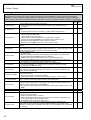
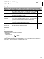
5. Parameter Description
A.. Inverter
Para. No. Description
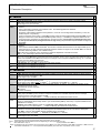
A00 1) Save parameter:
0: inactive;
1: The parameters of both parameter records are saved in non-volatile memory. Saving is triggered when the
value changes from 0 to 1. "A02 check parameter" is then performed automatically.
Read
parabox & save: Read parameters from Parabox or Controlbox and save in non-volatile memory.
A01•
First select desired data record (1 to 7), and then press
.
"A02 check parameter" is started automatically. When read errors occur, all parameters are rejected, and the
settings last saved with A00 are restored.
0: inactive;
1 to 7; Controlbox (number of the data record)
1)
Check parameter: Parameterization is checked for correctness. For possible results, see chap. 7.
A02
0: inactive;
1: active; Parameters of the parameter record to be edited (see A11) are checked for the following.
- Adherence to the value range
- (n-Max ÷ 60) x encoder incr. < 80 kHz. [(C01 ÷ 60) x F36 < 80 kHz]
- Correct programming of the binary inputs (F31 to F35)
- If control mode "vector-controlled with 2-track feedback" has been selected with B20=2, BE4 must be
programmed to encoder signal A (F34=14) and BE5 must be programmed to encoder signal B (F35=15).
to parabox: Write data of the inverter to external data medium (Controlbox)
A03 1) Write
0: inactive;
1 to 7; The parameters of both parameter records are copied from the inverter to Controlbox. For handling,
see A01.
1)
Default
settings:
All parameters are reset to their default settings.
A04•
0: inactive;
1: active; The procedure is triggered when the value changes from 0 to 1.
Menu level: Specifies the parameters which can be accessed by the user
A10
0: standard; Parameters which can be accessed are highlighted in gray. All parameters remain in effect
including those in the "1:extended" menu level.
1: extended; Access to all parameters
2: service; Access to rarely used service parameters. Small print (e.g., A37).
Parameter
set edit: Specifies the parameter record to be edited. The parameter record to be edited (A11) and
A11
the active parameter record (status indication) do not have to be identical. For example, parameter record 1 can
be edited while the inverter continues operation with parameter record 2. See also chapter 9.4 (FAS-Installation
instr., publication no. 441581).
1: parameter set 1; Parameter record 1 is edited.
2: parameter set 2; Parameter record 2 is edited.
Language: When the language is changed, FDS-Tool-specific texts U22, U32, U42 and U52 are reset to the
A12
default setting. This also applies to C53.
1: english;
2: french;
0: deutsch;
Set password: Password is requested. If a password is defined in A14, this must be entered here before
A13
parameters can be changed. See chapter 7.3 (FAS-Installation instr., publication no. 441581). If parameterized
with FDS Tool, no password required.
Edit
password: Definition and modification of the password. 0 means that no password has been set. All other
A14
values are valid passwords. See chapter 7.3 (FAS-Installation instr., publication no. 441581). A defined
password can only be read out via FDS Tool and only entered with Controlbox.
Auto-return: Permits automatic return from the menu to the status indication. In edit mode (i.e., the edited
A15
parameter is flashing), there is no automatic return to the status indication.
0: inactive;
1: active; If 50 seconds pass without a key being pressed, the display jumps back to the status indication.
P
Speed depends on pole number B10; fmax = 400 Hz. With a 4-pole motor, this is 12000 rpm at 400 Hz.
•
The power pack must be turned off before these parameters can be changed.
Italics These parameters are sometimes not shown depending on which parameters are set.
1)
See result table in chap. 9.
2) Only available when D90≠1
Parameters which are included in the normal menu scope (A10=0). For other parameters, select A10=1:extended or A10=2:service.
Parameters marked with a "√ " can be parameterized separately from each other in parameter record 1 and 2.
12
POSIDRIVE® FAS 4000 / Posi-Upgrade
STÖBER
ANTRIEBSTECHNIK
5. Parameter Description
A.. Inverter
Para. No. Description
Braking resistor type: Specification of the braking resistor type
A20
0: inactive; Braking transistor is deactivated. Too much braking energy causes fault "36:overcurrent"
1: user defined; For resistor values, see A 21, A22 and A23. Entering A20=1 and A22=0 automatically extends
the braking ramps when DC link voltage is too high.
2: 300Ohm0.15kW
A20 1 to 5: This information is used to create a thermal model which determines
3: 200Ohm0.15kW
the maximum permissible power which can be dissipated with the braking
4: 100Ohm0.15kW
resistor. This protects the braking resistance from thermal overload.
5: 100Ohm0.6kW
A thermal overload causes the fault "42:Temp.BrakeRes”
}
A21
A22
A23
A30•
A31
A32
A33
A34
A35
A36
Brake resistor resist.: Only with A20=1 (user defined), resistance value of the braking resistor used
Value range in Ω:: Depends on type, up to 600
Braking resistor rating: Only with A20=1 (user defined), capacity of the braking resistor used. Entering A22=0
KW automatically extends the ramps when DC link voltage is too high (if no braking resistor is connected, the
fault "36:Highvoltage" is avoided).
Value range in kW: 0 to ..., depends on type
Braking resistor therm.: Only with A20=1 (set as desired), thermal time constant of the braking resistor
Value range in sec: 0.1 to 40 to 100
Operation input: Specifies the origin of the control signals (i.e., enable, direction of rotation and reference
value)
0: control interface (X1); Control signals (e.g., enable and so on) are generated via the X1 terminals. All binary
inputs must be programmed accordingly. Fieldbus operation without Drivecom profile.
1: serial (X3); Control signals (e.g., enable and so on) are generated from the PC (FDS Tool software). The
inverter is connected to the PC via sub D plug connector X3 (RS 232-C interface). See chap. 9.9 (FAS-Intallation instr., publ. no. 441581). Remote control via the PC requires that the enable input (X1.6) be high.
2: fieldbus; The inverter is put into a drive-compatible mode for operation with communication. The device is
either controlled exclusively via the bus (the BEs should be set to "0:inactive" or in mixed operation). Signals
from the BEs (e.g., halt and limit switch (stop+, stop -) take priority over the fieldbus signals. If the control is
performed only via the fieldbus, the input functions (i.e., F25, and F31 to F35) must be set to "0:inactive."
Control of the drive via fieldbus requires that the enable input (X1.6) be high.
Esc-reset: Use the Esc key on Controlbox to acknowledge faults while they are being indicated.
0: inactive;
1: active; Faults can be acknowledged with Esc on Controlbox.
Auto-reset: Faults which occur are acknowledged automatically.
0: inactive;
1: active; The inverter acknowledges some faults automatically. See chapter 14 (FAS-Installation instr.,
publication no. 441581). Faults can be automatically acknowledged three times within a time period of 15
minutes (default setting). A fourth fault is not acknowledged automatically. Instead, relay 1 opens, and the
fault must be acknowledged in some other way (i.e., enable, binary input F31 to F35=13, or Esc key on
Controlbox A31). The time period for automatic acknowledgment can be parameterized from 1 to 255 min.
Time auto-reset: Time period for automatic acknowledgment. See A32.
Value range in min: 1 to 15 to 255
Auto-start: Before you activate auto-start A34=1, check to determine whether safety requirements permit an
automatic restart. Use only permitted when the standards or regulations pertaining to the system or machine are
adhered to.
0: inactive; After power-on, the enable must change from L level to H level to enable the drive (→ message
"12:inhibited"). This prevents the motor from starting up unintentionally (i.e., machine safety).
1: active; When auto-start is active, the drive can start running immediately (if enabled) after the power is turned
on.
Low voltage limit: If the inverter is enabled and the DC-link voltage is less than the value set here, the inverter
assumes fault "46:low voltage. " With three-phase devices, A35 should be approximately 85% of the network
voltage so that any failures in a phase can be compensated for.
Value range in V: depends on type
Mains voltage: Maximum voltage provided to the motor by the inverter. Usually the power voltage. Starting at
this voltage, the motor runs in the field weakening range. This specification is important for optimum adjustment
in control modes "sensorless vector-control" (B20=1) and "vector-control" (B20=2).
Value range in V: depends on type
P
Speed depends on pole number B10; fmax = 400 Hz. With a 4-pole motor, this is 12000 rpm at 400 Hz.
•
The power pack must be turned off before these parameters can be changed.
Italics These parameters are sometimes not shown depending on which parameters are set.
1)
See result table in chap. 9.
2) Only available when D90≠1
Parameters which are included in the normal menu scope (A10=0). For other parameters, select A10=1:extended or A10=2:service.
Parameters marked with a "√ " can be parameterized separately from each other in parameter record 1 and 2.
13
POSIDRIVE® FAS 4000 / Posi-Upgrade
STÖBER
ANTRIEBSTECHNIK
5. Parameter Description
A.. Inverter
Para. No. Description
Reset memorized values: The six different following error counters E33 to E38 (e.g., maximum current,
A37
maximum temperature and so on) are reset.
1)
Read
parabox: Read parameters from a Controlbox without automatic storage.
A40•
0: inactive;
1 to 7: active; For how it works, compare A01.
1)
Select parameter set: Two parameter records are available. These can be selected via the binary inputs or
A41•
directly via A41. The selected parameter record does not become active until the enable has been removed and
after a maximum of 300 msec have passed. Some parameters retain their validity in both parameter record 1
and parameter record 2. Parameters which can be programmed separately in parameter record 2 are indicated
by a between the coordinate and parameter name. See chap. 7.3.1(FAS-Installation instr., publ. no. 441581)).
0: external; The active parameter record is selected via binary inputs BE1 to BE5. At least one of the parameters F30 to F34 must be set to 11 (parameter set-select) in both parameter records. Parameter record 1 is
active when a LOW signal is present on BE. Parameter rec. 2 is active when a HIGH signal is present on BE.
1: parameter set 1; The inverter uses parameter record 1. External selection is not possible.
2: parameter set 2; The inverter uses parameter record 2. External selection is not possible.
Caution: Parameter A41 is only provided for testing purposes. It is not saved with A00=1. Use a BE or the
E101 parameter (bus access) if you want to switch parameter records during operation.
Copy
parameter
set 1>2: Copies parameter record 1 to parameter record 2. The old values of parameter
A42
record 2 are overwritten. The procedure is started when the value changes from 0 to 1.
The result is always "0:error free." The new parameter assignment must be stored in non-volatile memory with
A00.
0: error free;
1)
Copy parameter set 2>1: Same as A42 except parameter record 2 is copied to parameter record 1
A43•
0: error free;
Tip: Permits commissioning with minimum circuiting of the control terminal as long as A51 is entered.
A50
0: inactive; Normal operation
1: active; The controller only requires a high signal on the "enable" input. All other binary control signals have
no function when C60<2. The
and
keys on Controlbox can be used to accelerate the drive
counterclockwise or clockwise to the speed set in A51. Since an enable is generated which has a higher
priority than the additional enable, operation remains possible even when additional-enable = low via fieldbus.
Tip
reference value: Reference value for speed for commissioning without external circuiting of the control
√
A51
inputs. The "enable" input must be high! The current actual speed is shown on the right of the display. When
A50=1 and A51 is in input mode (value flashing), A51 becomes active as continuous reference value. For
behavior of enable and BEs, see A50.
P
P
P
Value range in rpm: -12000 ... 300 ... 12000
Key hand function: Can be used to disable the MANUAL
key on Controlbox for turning local operation
A55
on/off. For additional information, see Controlbox documentation (publ. no.: 441479).
0: inactive;
key has no function.
1: local;
key activates local operation. Device enabling is then handled exclusively by the keys "green I“
. The
and
keys can be used to move backward and forward in the status display. Active
and "red 0“
local operation and active enable are indicated by LEDs on Controlbox. The reference speed results from
A51 for speed mode.
key (LED goes off), the drive immediately switches
CAUTION: When local operation is disabled with the
back to the queued control signals (i.e., danger of unintentional startup!).
A80
A82
A83
P
Serial address: Only when A10=2. Address for communication via X3 with FDS Tool and with master via USS protocol (cf.
®
®
documentation “USS link for POSIDRIVE and POSIDYN ”, publ. no.: 441564)
Value range: 0 to 31
CAN-baudrate: Sets the baud rate for the Kommubox CAN bus. Compare CAN bus documentation (publ. no.:
441562).
0: 10 kBit/s
3: 100 kBit/s
6: 500 kBit/s
1: 20 kBit/s
4: 125 kBit/s
7: 800 kBit/s
2: 50 kBit/s
5: 250 kBit/s
8: 1000 kBit/s
Busaddress: Specifies the device address for use with the fieldbus (i.e., Kommubox). For permissible value
range, see documentation of the applicable Kommubox. A83 has no effect on device programming via PC with
FDS Tool or via the RS 232 interface with the USS protocol.
Value range: 0 to 125
Speed depends on pole number B10; fmax = 400 Hz. With a 4-pole motor, this is 12000 rpm at 400 Hz.
•
The power pack must be turned off before these parameters can be changed.
Italics These parameters are sometimes not shown depending on which parameters are set.
1)
See result table in chap. 9.
2) Only available when D90≠1
Parameters which are included in the normal menu scope (A10=0). For other parameters, select A10=1:extended or A10=2:service.
Parameters marked with a "√ " can be parameterized separately from each other in parameter record 1 and 2.
14
POSIDRIVE® FAS 4000 / Posi-Upgrade
STÖBER
ANTRIEBSTECHNIK
5. Parameter Description
A.. Inverter
Para. No. Description
Profibus baudrate: When the FAS is used with the PROFIBUS-DP Kommubox, the baud rate found on the bus
A84
is indicated (!) here. Compare PROFIBUS-DP documentation (publ. no.: 441535).
0: not found
3: 45,45kBit/s
6: 500 kBit/s
9: 6000kBit/s
1: 9.6kBit/s
4: 93,75kBit/s
7: 1500kBit/s
10: 12000kBit/s
2: 19.2kBit/s
5: 187,5kBit/s
8: 3000kBit/s
B.. Motor
B00•
B10•
B11•
B12
B13
B14•
B15•
B16
Description
Motor-type: Motor selection from the motor data base. The STÖBER system motor used is specified with
B00=1 to 20. B00=0 (user defined) is used for special windings or motors of other manufacturers.
0: user defined; Number of poles, P, I, n. V, f and cos PHI must be specified in B10 to B16. It is essential to
perform and store B41 (auto-tuning). Auto-tuning of the motor determines the winding resistors. This is
required for optimum adjustment between inverter and motor.
1: 63K Y 0.12kW
6: 71K D 0.25kW
11: 80L Y 0.75kW
16: 90L D 1.5kW
2: 63K D 0.12kW
7: 71L Y 0.37kW
12: 80L D 0.75kW
17: 100K Y 2.2kW
3: 63M Y 0.18kW
8: 71L D 0.37kW
13: 90S Y 1.1kW
18: 100K D 2.2kW
4: 63M D 0.18kW
9: 80K Y 0.55kW
14: 90S D 1.1kW
19: 100L Y 3kW
5: 71K Y 0.25kW
10: 80K D 0.55kW
15: 90L Y 1.5kW
20: 100L D 3kW
All necessary data are stored for these types of motors in a data base. This permits optimum adjustment
between motor and inverter. Parameters B10 to B16 are not shown.
√
An "*" on the display (Controlbox) means that at least one of the parameters (B53, B64 and B65) differs from
the default setting of the STÖBER motor database.
Poles: Calculated from the nominal speed of the motor p=2 (f x 60/nNom). Internally, the controller works with
frequencies. Correct speed indication requires entry of the number of poles.
Value range: 2 to 4 to 16
P-nominal: Nominal power as per nameplate
Value range in kW: 0.12 ... (depends on type)
I-nominal: Nominal current as per nameplate. Remember type of connection (Y/∆) of the motor must
correspond to B14.
Value range in A:0 ... (depends on type)
n-nominal: Nominal speed as per nameplate
P
(P Depends on pole number B10; fmax = 400 Hz)
Value range in rpm: 0 to (depends on type) to 12000
V-nominal: Nominal voltage as per nameplate. Remember type
Field weakenof connection (Y/∆) of the motor must correspond to B12.
ing range
Value range in V: 0 to (depends on type) to 480
√
√
√
√
√
A36
f-nominal: Nominal frequency of the motor as per nameplate. The (V-mains)
slope of the V/f curve and thus the characteristics of the drive are
B14
specified with parameters B14 and B15. The V/f curve determines (V-nom.)
the frequency (F15: f-nominal) at which the motor is operated with
the nominal voltage (B14: V-nominal). Voltage and frequency can
be increased linearly to more than the nominal point. The upper
voltage limit is the power voltage which is present. STÖBER system
motors up to model 112 offer the capability of star/delta operation.
Operation with 400 V ∆ makes it possible to increase power by the
factor √3 and provide an expanded speed range with constant torque.
With this type of connection, the motor has increased current requirements.
The following must be ensured:
– The frequency inverter is designed for this power
(P∆ = √3 x PY).
– B12 (I-nominal) is parameterized to the appropriate nominal motor
current (I∆Nom = √3 x IYNom).
Value range in Hz: 10 to 50 to 330
cos PHI: The cos Phi of the nameplate of the motor is required for control.
Value range: 0.50 to (depends on type) to 1
√
Nom. point
B15 (f-nom.)
Y circuit
Motor circuits
Para No.
∆ circuit
√
P
Speed depends on pole number B10; fmax = 400 Hz. With a 4-pole motor, this is 12000 rpm at 400 Hz.
•
The power pack must be turned off before these parameters can be changed.
Italics These parameters are sometimes not shown depending on which parameters are set.
1)
See result table in chap. 9.
2) Only available when D90≠1
Parameters which are included in the normal menu scope (A10=0). For other parameters, select A10=1:extended or A10=2:service.
Parameters marked with a "√ " can be parameterized separately from each other in parameter record 1 and 2.
15
POSIDRIVE® FAS 4000 / Posi-Upgrade
STÖBER
ANTRIEBSTECHNIK
5. Parameter Description
B.. Motor
Para No.
B20•
B21•
B22
B23
B24•
B25•
B27
B30
B31
P
Description
Control mode: Specifies the type of motor control.
0: V/f-control; V/f control changes voltage and frequency proportionally to each other so that machine flow
remains constant. Utilized, for example, when reluctance motors or several motors are used with one inverter.
1: sensorless vector-control (SLVC); Vector control without feedback. Much better speed accuracy and
dynamics. B31, B32 and C30 can be used to manipulate dynamic reactions.
2: vector-control feedback; Vector control with feedback. The signals of the speed feedback are evaluated by
the inverter via binary inputs BE4/BE5. F34=14 and F35=15 must be parameterized. For commissioning, see
chap. 9.6 (FAS-Installation instr., publication no. 441581).
V/f-characteristic: Effective regardless of the control mode selected in B20.
0: linear; Voltage/frequency characteristic is linear. Suitable for all applications.
1: square; Square characteristic for use with fans and pumps
V/f-gain: Offset factor for the slope of the V/f curve
B22 V/f gain
The slope for V/f-gain=100% is specified by V-nom. (B14)
A36
and f-nom. (B15).
(V-mains)
Nom. point
Value range in %: 90 to 100 to 110
B14
Boost: Only effective when B20=0 (V/f-control)
(V-nom)
Boost means an increase in voltage in the lower speed range
B23
(Boost)
which provides more startup torque. With a boost of 100%,
nominal motor current begins flowing at 0 Hz. Determination
of required boost voltage requires that the stator resistance of the
B15
motor be known. If B00=0 (user defined), it is essential to perform B41 (autotuning).
(f-nom.)
If B00=1 to 20, the stator resistance of the motor is specified by the motor selected.
Value range in %: 0 to 10 to 400
Switching frequency: The noise emission of the drive is reduced by changing the switching frequency.
However, since increasing the switching frequency also increases loss, permissible nominal motor current (B12)
must be reduced if the switching frequency is increased. At a switching frequency of 16 kHz and VMains = 400 V,
the inverter is able to supply a continuous current of 46% of its nominal current. At 8 kHz, it can supply 75%. For
applications starting with 200 Hz, the switching frequency must be set to 8 kHz. The switching frequency is
automatically reduced based on the thermal model (E22).
Value range in kHz: 4 to 16 (adjustable in 2 kHz increments)
Halt flux: Only if B20≠0. B25 specifies whether the motor remains powered during halt and quick stop when the
brakes have been applied. After a HALT, the motor remains fully powered for the time B27. Output signal
"22:ready for reference value“ indicates that the magnetic field is being generated.
0: inactive; When the brakes are applied (halt, quick stop), power is withdrawn from the motor, and the motor is
demagnetized. The advantage of this is improvement of thermal motor balance since the motor has time to
cool off during the pauses. The disadvantage of this is the increased time required for remagnetization (i.e.,
rotor time constant, approx. 0.5 sec). The inverter automatically determines how much time is required and
adds this to brake release time F06.
1: active; Default setting. Magnetization current flows through the motor and speeds up reaction to brake
release. Disadvantage: The motor heats up, and the magnetization current can be up to 40% of the nominal
current depending on the size of the motor.
2: 75%; Current reduced to 75%. Otherwise same as B25=0.
3: 50%;
4: 25%;
Time halt flux: When a reduction of halt flux B25 occurs, the full magnetization current is still retained for time
B27 when the brakes are applied and the power pack is active (e.g., HALT signal).
Value range in sec: 0 to 255
Addit.motor-operation: Only if B20=0 (V/f-control). For multiple-motor operation. Permits an additional motor
to be connected to the enabled inverter. Motor voltage is briefly reduced to prevent overcurrent switchoff.
0: inactive;
1: active;
Oscillation damping: When idling, large motors may tend to sympathetic vibration. Increasing the parameter
B31 damps these oscillations when B20=2:SLVC. Values from 60 to 100% are suitable for difficult drives.
With B20=2:Vector Control, B31 limits the possibility, during generator operation, of using the increase in the
rise of DC link voltage to increase magnetization and thus braking torque. This can have a positive effect on
smoothness of running when the drive is alternating between motor and generator operation at a constant
higher speed.
Value range in %: 0 to 30 to 100
Speed depends on pole number B10; fmax = 400 Hz. With a 4-pole motor, this is 12000 rpm at 400 Hz.
•
The power pack must be turned off before these parameters can be changed.
Italics These parameters are sometimes not shown depending on which parameters are set.
1)
See result table in chap. 9.
2) Only available when D90≠1
Parameters which are included in the normal menu scope (A10=0). For other parameters, select A10=1:extended or A10=2:service.
Parameters marked with a "√ " can be parameterized separately from each other in parameter record 1 and 2.
16
√
√
√
√
√
√
√
√
√
POSIDRIVE® FAS 4000 / Posi-Upgrade
STÖBER
ANTRIEBSTECHNIK
5. Parameter Description
B.. Motor
Para No.
B32
B40•1)
B41•1)
B53
B64
B65
Description
SLVC-dynamics: B32 can be used to manipulate the speed at which SLVC reacts to changes in load.
B32=100% means greatest dynamics.
Value range in %: 0 to 70 to 100
Phase test:
0: inactive;
1: active; Tests motor symmetry in increments of 60°. The following points are checked:
- Connection of phases U, V and W
- Symmetry of the winding resistance of the phases U, V and W. If a winding resistor deviates by ±10%, the
inverter reports "19:symmetry".
- Type of connection of the motor. If a STÖBER system motor has been selected with parameter B00=1 to 20,
the type of connection of the selected STÖBER system motor (i.e., star/delta) is compared with that of the
connected motor. Deviations are reported with "20:motorConnect." The function is started when the level
on the input enable (X1.6) changes from low to high. Exiting the parameter requires another low signal on
the enable.
Autotuning:
0: inactive;
1: active; Stator resistance B53 is measured. The function is started when the level on the input enable (X1.6)
changes from low to high. Exiting the parameter requires another low signal on the enable. A00=1 is used to
save the measuring results in non-volatile memory.
B00=0, Be sure to autotune motor. Important for optimum adjustment of inverter and motor.
B00=1 ... 20, autotuning of the motor is not required.
√
√
R1-motor: Stator resistance of the motor winding, R1=Ru-v/2. Usually only entered for non STÖBER motors or autotuning with
B41. In the Y circuit, B53 directly corresponds to the branch resistance. In the ∆ circuit, 1/3 of the branch resistance must be
entered. With STÖBER motors, B53 should usually not be changed. Value is adjusted with B41 (autotuning). An "*" indicates
deviation from the STÖBER motor data base.
Value range in Ω: 0.01 to depends on type to 327.67
Ki-IQ (moment): Only when B20=2. Integral gain of the torque controller.
Value range in %: 0 to depends on type to 400
Kp-IQ (moment): Only when B20=2. Proportional gain of the torque controller.
Value range in %: 0 to depends on type to 400
√
√
C.. Machine
Para. No. Description
n-Min: Minimum permissible speed. The speed is related to the motor shaft speed. Reference values less than
C00
n-Min are ignored and raised to n-Min.
Value range in rpm: 0 to C01
n-Max: Maximum permissible speed. The speed is related to the motor shaft speed. Reference values over
C01
n-Max are ignored and limited to n-Max.
P
P
(P = depends on poles B10; fmax = 400 Hz)
Value range in rpm: C00 to 3000 to 12000
Perm. direction of rotat.: Determines the permissible direction of rotation. The direction of rotation can be
C02•
specified via the binary inputs.
0: clockwise & counter-clockwise;
1: clockwise;
2: counter-clockwise;
M-Max 1: Maximum torque in % of nominal motor torque. The active torque limit can be further reduced with an
C03
analog input (see F25=2). If the maximum torque is exceeded, the controller responds with the message
"47:drive overload." See also remarks for C04.
Value range in %: 0 to 150 to 400%*
* Value is limited by the maximum inverter current.
M-Max
2:
Additional
torque
limit.
You
can
switch between C03 and C04 with a binary input (F3..=10:torque
C04
select) or automatically when startup mode= cycle characteristic (C20=2). See chap. 9.2 (FAS-Installation instr.,
publication no. 441581).
Remarks: Since C04 is always active for a quick stop, C04 ≥ C03 should usually apply!
Value range in %: 0 to 150 to 400%*
* Value is limited by the maximum inverter current.
Skip
speed
1:
Prevents
prolonged
use
of
the drive in a frequency range which produces mechanical
C10
resonance. The drive goes through the entered speeds and tolerance band of ±0.4 Hz with the decel-quick
ramp (D81). The four "skip speeds" can be specified next to each other.
Value range in rpm: 0 to 12000 P (P depends on poles B10; fmax = 400 Hz)
Skip speed 2: See C10.
C11
Value range in rpm: 0 to 12000 P
√
√
√
√
√
√
√
P
Speed depends on pole number B10; fmax = 400 Hz. With a 4-pole motor, this is 12000 rpm at 400 Hz.
•
The power pack must be turned off before these parameters can be changed.
Italics These parameters are sometimes not shown depending on which parameters are set.
1)
See result table in chap. 9.
2) Only available when D90≠1
Parameters which are included in the normal menu scope (A10=0). For other parameters, select A10=1:extended or A10=2:service.
Parameters marked with a "√ " can be parameterized separately from each other in parameter record 1 and 2.
17
POSIDRIVE® FAS 4000 / Posi-Upgrade
STÖBER
ANTRIEBSTECHNIK
5. Parameter Description
C.. Machine
Para. No. Description
Skip speed 3: See C10.
C12
P
Value range in rpm: 0 to 12000
Skip speed 4: See C10.
C13
Value range in rpm: 0 to 12000 P
Startup mode: Determines the startup behavior of the drive
C20•
0: standard; Default setting. Separate from control mode (B20).
1: load start; Only if B20=1 (sensorless VC). For machines with increased breakaway torque. The motor torque
is increased to M-load start (C21) during the time t-load start (C22). After expiration of this time, the inverter
uses the standard ramp again.
2: cycle characteristic; Effective separately from the control mode (B20).
- Automatic switch between the specified torque limits M-Max 1 (C03) and M-Max 2 (C04). M-Max 1 applies
during constant travel. M-Max 2 applies during the acceleration phase.
- If B20=1 (sensorless vector control), a torque precontrol procedure is performed (i.e., the inverter calculates
the required torque from the motor type specified (B00) and the ratio of load/motor inertia (C30). This
calculated torque is then given to the drive.
3: capturing; Only if B20=1. A rotating motor is connected to the inverter. The inverter determines the actual
speed of the motor, synchronizes itself, and specifies the appropriate reference value.
M-load start: Only if C20=1 (load start). Specification of the torque for the load start.
C21
Value range in %: 0 to 100 to 400
t-load start: Only if C20=1. Time for the load start with the torque defined in C21.
C22
Value range in sec: 0 to 5 to 9.9
J-mach/J-motor: Ratio of the inertia of load to motor. This factor is effective for all control modes and is
C30
important for optimization between inverter and motor (i.e., dynamics). Entry is not mandatory.
Value range: 0 to 1000
n-controller Kp
n-controller
Kp: Only if B20=2 (vector control with feedback).
C31
n-post
Proportional gain of the speed controller.
n-contr. Ki
ramp
Value range in %: 0 to 60 to 400
M-ref.val.
√
√
√
√
√
√
√
n-motor
C32
C35
C40
C41
C42
C43
C44
C45
C46
P
n-controller Ki: Only if B20=2. Integral gain of the speed controller. Reduce C32 when overswinging occurs in
the target position.
Value range in %: 0 to 30 to 400
n-control. Kp standstill:
C31 and C32 are multiplied by C35 as soon as the motor speed drops below C40.
Value range in %: 5 to 100
n-window: If F00=3 (relay 2 as signal relay for "3:reference value-reached") or F00=2 (relay 2 as signal contact
for speed "2:standstill"), the reference value is considered achieved in a window of reference value ±C40, and
relay 2 closes. A halting brake is not activated as long as [n] > C40.
Value range in rpm: 0 to 30 to 300 P
Operating range n-Min: Parameters C41 to C46 can be used to specify an operating area. An output (F00=6)
can be used to signal that these values have been exceeded. All area monitoring procedures are performed at
the same time. If area monitoring is not required, the minimum parameters must be set to the lower-limit values,
and the maximum parameters must be set to the upper-limit values. Cf. chapter 9.3 (FAS-Installation instr.,
publication no. 441581). When C49=0, operating-range monitoring is suppressed when the motor is not
powered and during acceleration/braking procedures. When C48=1, amount generation is activated.
Value range in rpm: 0 to C42
Operating range n-Max: See C41.
Value range in rpm: C41 to 6000 P to 12000 P (P depends on poles B10; fmax = 400 Hz)
Operating range M-Min: See C41.
Value range in %: 0 to C44
Operating range M-Max: See C41.
Value range in %: C43 to 400
Operating range X-Min.: See C41. Monitors range defined in C47.
Value range in %: -400 to 0 to C46
Operating range X-Max.: See C41. Monitors range defined in C47.
Value range in %: C45 to 400
Speed depends on pole number B10; fmax = 400 Hz. With a 4-pole motor, this is 12000 rpm at 400 Hz.
•
The power pack must be turned off before these parameters can be changed.
Italics These parameters are sometimes not shown depending on which parameters are set.
1)
See result table in chap. 9.
2) Only available when D90≠1
Parameters which are included in the normal menu scope (A10=0). For other parameters, select A10=1:extended or A10=2:service.
Parameters marked with a "√ " can be parameterized separately from each other in parameter record 1 and 2.
18
√
√
√
√
√
√
√
√
√
POSIDRIVE® FAS 4000 / Posi-Upgrade
STÖBER
ANTRIEBSTECHNIK
5. Parameter Description
C.. Machine
Para. No. Description
Operating range C45/C46: Defines the range to be monitored.
C47
5: E22 i2t-device;
0: E01 P-motor;
1: E02 M-motor;
6: E23 i2t-motor;
2: E10 AE1-level;
7: E24 i2t-braking resistor;
C48
C49
C50
C51
C52
C53
C60•
√
8: E62 actual M-Max;
10: E71 AE1-scaled;
13: E14 BE5-frequency RV;
14: E08 n-motor; (% ref. to C01)
√
Operating range of amount C47:
0: absolute; First, the amount is generated from the signal selected in C47.
Example: C47=AE1; C45=30%; C46=80%. The operating range is -80% to -30% and +30% to +80%.
1: range; The signal selected in C47 must be located in range C45 to C46.
Example: C47=AE1, C45= -30%, C46= +10%. The operating range is -30% to +10%.
Operating range accel&ena:
0: inactive; During acceleration or deactivated enable, the "operating range" signal for the binary outputs is set
to "0"=ok. The three ranges are only monitored during stationary operation (compatible with device software
V 4.3).
1: active; The operating range is always monitored..
Display function: Parameters C50 to C53 can be used to design the first line of the display as desired. See
chapter 7.3.1, FAS-Installation instr., publication no. 441581). Eight characters are available for a number, and
8 characters are available for any unit. Display value=raw value/display factor.
0: n2 & I-motor;
1: E00 I-motor; The inverter supplies the actual motor current in amperes as the raw value.
2: E01 P-motor; The inverter supplies as the raw value the actual active power as a percentage of the nominal
motor power.
3: E02 M-motor; As the raw value, the inverter supplies the actual motor torque as a percentage of the nominal
motor torque.
4: E08 n-motor; The inverter supplies the actual speed in rpm as the raw value. If V/f control (B20=0) and
sensorless vector control (B20=1), the frequency (i.e., motor speed) output by the inverter is indicated. Only
with vector control with feedback (B20=2) is the real actual speed indicated.
Display factor: Raw value (C50) is divided by the value entered here.
Value range: -1000 to 1 to 1000
Display decimals: Number of positions after the decimal point for the value in the display.
Value range: 0 to 5
Display text: Only if C60≠2 (run mode≠position) and if C50>0. Text for customer-specific unit of measure in the
operating display (e.g., "units/hour"). Maximum of 8 positions. Can only be entered with FDS Tool.
Run mode
1: speed; Reference value for speed, conventional operating mode.
2: position; Position control activated. When enable signal on X1.6, the position controller is turned on, and the
current position is maintained. Full functionality of the position controller is only available with incremental
encoders (B20=2). If C60=2, group "D. reference value") is completely faded out.
When the mode is switched from speed to position, the reference position is lost.
√
√
√
√
√
√
P
Speed depends on pole number B10; fmax = 400 Hz. With a 4-pole motor, this is 12000 rpm at 400 Hz.
•
The power pack must be turned off before these parameters can be changed.
Italics These parameters are sometimes not shown depending on which parameters are set.
1)
See result table in chap. 9.
2) Only available when D90≠1
Parameters which are included in the normal menu scope (A10=0). For other parameters, select A10=1:extended or A10=2:service.
Parameters marked with a "√ " can be parameterized separately from each other in parameter record 1 and 2.
19
POSIDRIVE® FAS 4000 / Posi-Upgrade
STÖBER
ANTRIEBSTECHNIK
5. Parameter Description
D.. Reference Value
Para. No. Description
Reference value accel: Acceleration ramp for the analog reference value input. Is only used for specification of
D00
reference value via terminal strip X1 and motor potentiometer.
- Voltage, current via analog input 1 (X1.2 – X1.4).
- Frequency via binary input BE5 (X1.5 – X1.11).
- Motor potentiometer via the binary inputs (D90=1)
Value range in sec/150 Hz * D98: 0 to 3 to 3000
Reference value decel: Deceleration ramp for the analog reference value input. Is only used for specification of
D01
reference value via terminal strip X1 and motor potentiometer.
- Voltage, current via analog input 1 (X1.2 – X1.4).
- Frequency via binary input BE5 (X1.5 – X1.11).
- Motor potentiometer via the binary inputs (D90=1)
Value range in sec/150 Hz * D98: 0 to 3 to 3000
2)
Speed (max. ref. value): Parameters D02 to D05 can be used to specify as desired the relationship between
D02
analog reference value and speed with a reference value characteristic curve. D02: Speed achieved with the
maximum reference value (D03). With C01<D02, "7:n>nmax“ is indicated when C01 is exceeded.
P
P
(P Depends on pole number B10; fmax = 400 Hz)
Value range in rpm: 0 to 3000 to 12000
value-Max.: Reference value to which the speed (max. RV) (D02) is assigned. Percentage of the
D032) Reference
analog reference value (10 V=100%) at which the maximum speed (D02) is achieved.
Value range in %: D05 to 100
with minimum reference value (D05).
D042) Speed (min. ref. value): SpeedP achieved
(P Depends on pole number B10; fmax = 400 Hz)
Value range in rpm: 0 to 12000
Reference value-Min.: Reference value to which the speed (min. RV) (D04) is assigned. Percentage of the
D052) analog
reference value (10 V=100%) at which the minimum speed (D04) is achieved.
Value range in %: 0 to D03
D062) Reference value offset: Corrects an offset on analog input 1 (X1.2 to 4). When the ref. value is 0, the motor
may not be permitted to rotate. If a revolution occurs anyway, this value must be entered with reversed sign as
the offset (e.g., if param. E10 shows 1.3%, D06 must be parameterized to -1.3%). The value range is ±100%.
While the ref. value offset is being entered, the current value of the analog input is shown at the same time (only
when Controlbox is connected).
Value range in %: -100 to 0 to 100
2)
Reference value enable: When the minimum reference value (D05) is set to a value greater than 1%, an
D07•
enable can be derived from the reference value output.
0: inactive;
1: active; An additional enable is derived from the reference value on analog input 1. If the reference value
enable is high, the output is greater than or equal to the minimum reference value (D05). If the reference
value enable is low, the output is less than the minimum reference value (D05).
reference value: Monitors reference value output. Monitors for wire break. Ref. value monitoring will
D082) Monitor
only function if the minimum reference value specified in D05 is greater than or equal to 5% (D05 > 5%).
0: inactive;
1: active; If the reference value output is 5% less than the minimum permissible reference value (D05), the
inverter shows "43:RV wire brk."
2)
Fix
reference value no.: Selection of a fixed reference value
D09
0: external selection via binary inputs and BE functions RV-select 0 to 2
1 to 7: fixed selection of fixed reference value. BE inputs are ignored.
2)
Accel 1: Up to 7 fixed reference values/ramp records can be defined per parameter record. Selection is made
D10
via the binary inputs. At least one binary input must be programmed to reference value selector
(e.g., F31=1:RV-select0). The reference value selector is used to assign the fixed reference values or ramp
records to the signals of the binary inputs. The result of the binary coding is shown in E60 (0 to 7). The ramp
records accel 1 to 7 / decel 1 to 7) are only active in connection with the assigned fixed reference values 1 to 7.
Accel 1: Acceleration time for ramp record 1 as related to 150 Hz.
Value range in sec/150 Hz * D98: 0 to 6 to 3000
1: Deceleration time for ramp record 1 as related to 150 Hz.
D112) Decel
Value range in sec/150 Hz * D98: 0 to 6 to 3000
reference value 1: Selection is made parallel to ramp record 1.
D122) Fix
(Accel 1 / decel 1) via the binary inputs
Value range in rpm: -12000P to 750P to 12000P
P
Speed depends on pole number B10; fmax = 400 Hz. With a 4-pole motor, this is 12000 rpm at 400 Hz.
•
The power pack must be turned off before these parameters can be changed.
Italics These parameters are sometimes not shown depending on which parameters are set.
1)
See result table in chap. 9.
2) Only available when D90≠1
Parameters which are included in the normal menu scope (A10=0). For other parameters, select A10=1:extended or A10=2:service.
Parameters marked with a "√ " can be parameterized separately from each other in parameter record 1 and 2.
20
√
√
√
√
√
√
√
√
√
√
√
√
√
POSIDRIVE® FAS 4000 / Posi-Upgrade
STÖBER
ANTRIEBSTECHNIK
5. Parameter Description
D.. Reference Value
Para. No. Description
D202) Accel 2: Acceleration time for ramp rec. 2 as related to 150 Hz.
No. Accel Decel Reference Value
Value range in sec/150 Hz * D98: 0 to 9 to 3000
D00
D01 Analog, freq.,...
0
D212) Decel 2: Deceleration time for ramp rec. 2 as related to 150 Hz.
D10
D11 Fixed RV 1
1
Value range in sec/150 Hz * D98: 0 to 9 to 3000
2)
Fix
reference
value
2:
Selection
is
made
parallel
to
ramp
rec.
2.
D20
D21 Fixed RV 2
2
D22
..
..
..
..
(Accel 2/decel 2) via the binary inputs
Value range in rpm: -12000 to 1500 to 12000
D70
D71 Fixed RV 7
7
D302) Accel 3: Acceleration time for ramp rec. 3 as related to 150 Hz.
Value range in sec/150 Hz * D98: 0 to 12 to 3000
2)
Decel 3: Deceleration time for ramp rec. 3 as related to 150 Hz.
D31
Value range in sec/150 Hz * D98: 0 to 12 to 3000
2)
Fix reference value 3: See D12.
D32
Value range in rpm: -12000P to 3000P to 12000P
Accel 4: Acceleration time for ramp record 4 as related to 150 Hz.
D402) Value
range in sec/150 Hz * D98: 0 to 0.5 to 3000
2)
Decel
4: Deceleration time for ramp record 4 as related to 150 Hz.
D41
Value range in sec/150 Hz * D98: 0 to 0.5 to 3000
Fix reference value 4: See D12.
D422) Value
range in rpm: -12000P to 500P to 12000P
2)
Accel 5: Acceleration time for ramp record 5 as related to 150 Hz.
D50
Value range in sec/150 Hz * D98: 0 to 1 to 3000
5: Deceleration time for ramp record 5 as related to 150 Hz.
D512) Decel
Value range in sec/150 Hz * D98: 0 to 1 to 3000
Fix reference value 5: See D12.
D522) Value
range in rpm: -12000 P to 1000 P to 12000 P
2)
Accel 6: Acceleration time for ramp record 6 as related to 150 Hz.
D60
Value range in sec/150 Hz * D98: 0 to 2 to 3000
6: Deceleration time for ramp record 6 as related to 150 Hz.
D612) Decel
Value range in sec/150 Hz * D98: 0 to 2 to 300
Fix reference value 6: See D12.
D622) Value
range in rpm: -12000 P to 2000 P to 12000 P
2)
Accel 7: Acceleration time for ramp record 7 as related to 150 Hz.
D70
Value range in sec/150 Hz * D98: 0 to 2.5 to 3000
7: Deceleration time for ramp record 7 as related to 150 Hz.
D712) Decel
Value range in sec/150 Hz * D98: 0 to 2.5 to 3000
Fix reference value 7: See D12.
D722) Value
P
P
P
range in rpm: -12000 to 2500 to 12000
Ramp
shape:
D80
0: linear;
1: ´S´ ramp; Smoother acceleration/deceleration.
Decel-quick: Quick stop ramp. Effective if a binary input is programmed to quick stop (F3..=9) or parameter
D81
F38>0. When a quick stop is triggered by the binary inputs, the drive is decelerated with the deceleration ramp
set here. In position mode (C60=2), quick stop is performed on ramp I11.
Value range in sec/150 Hz * D98: 0 to 0.2 to 3000
Reference value source: See block circuit diagram in chap. 16 (FAS-Installation instr., publication no. 441581).
D90•
0: standard reference value;
1: motor potentiometer; Two binary inputs can be used to simulate a "motor
Motor poti.
BE4 BE5
potentiometer." This requires that one binary input be programmed to
ref. value
"4:motorpoti up" and another binary input to "5:motorpoti dwn"
L
L
Constant
(e.g., F34=4 and F35=5). Only ramps D00 and D01 can change the speed.
H
L
Larger
2: motor potentiometer+reference value; The reference value for speed of the
L
H
Smaller
motor potentiometer function is added to the "standard" reference value
H
H
0
(i.e., analog input, fixed reference values). When D90=1, only the motor
√
√
√
√
√
√
√
√
√
√
√
√
√
√
√
√
√
√
√
√
√
potentiometer reference value is used. The ramps selected with the binary
inputs are used, and the motor potentiometer reference value changes with
RV-accel/RV-decel (i.e., D00 and D01).
P
Speed depends on pole number B10; fmax = 400 Hz. With a 4-pole motor, this is 12000 rpm at 400 Hz.
•
The power pack must be turned off before these parameters can be changed.
Italics These parameters are sometimes not shown depending on which parameters are set.
1)
See result table in chap. 9.
2) Only available when D90≠1
Parameters which are included in the normal menu scope (A10=0). For other parameters, select A10=1:extended or A10=2:service.
Parameters marked with a "√ " can be parameterized separately from each other in parameter record 1 and 2.
21
POSIDRIVE® FAS 4000 / Posi-Upgrade
STÖBER
ANTRIEBSTECHNIK
5. Parameter Description
D.. Reference Value
Para. No. Description
Motorpoti function: Only if D90≠0 (reference value source≠standard RV)
D91
0: non-volatile; The reference value which was approached is retained both when the enable is removed and
when the power is turned off/on.
1: volatile; The reference value is set to 0 when the enable becomes low or the power for the drive is turned off.
Negate reference value: See block circuit diagram in chap. 16.
D92
0: inactive;
1: active; The reference value channel is negated. Corresponds to a reverse in direction of rotation. Not related
to the selected reference value.
RV-generator: For commissioning and optimizing the speed controller.
D93
0: inactive; Normal reference value selection.
1: active; ±A51 is specified cyclically as reference value. The time can be set in D94.
Ref. val. generator time: After this period of time, the sign of the reference value changes when D93=1:active.
D94
Value range in msec: 0 to 500 to 32767
D98
Ramp factor: If D98<0 and speed mode (C60=1), all ramps (e.g., D00) are shortened by one or two powers of ten. This
makes very sensitive setting of short ramps possible.
-2: *0.01 All ramp times shortened by factor of 100.
-1: *0.1 All ramp times shortened by factor of 10.
Factory setting. Ramps unchanged.
0: *1
E.. Display Values
Para. No. Description
E00
E01
E02
E03
E04
I-motor: Indicates the active motor current in amperes.
P-motor: Indicates the current power of the motor in kW and as a relative percentage in relation to nominal
motor power.
M-motor: Indicates the current motor torque in Nm and as a relative percentage in relation to nominal motor
torque (only on display of Controlbox).
DC-link-voltage: Indicates the current DC-link voltage.
Value range for single-phase inverters: 0 to 500 V,
Value range for three-phase inverters: 0 to 800 V
V-motor: Indicates the current motor voltage.
Value range for single-phase inverters: 0 to 230 V,
Value range for three-phase inverters: 0 to 480 V
E05
E06
E07
E08
E09
f1-motor: Indicates the current motor frequency in Hz.
E10
E12
AE1-level: Level of the signal present on analog input (AE) 1 (X1.2 to 4). ±10 V is 100%.
E13
E14
E15
E17
P
n-reference value: Only if C60=1 (speed). Indicates the current ref. val. for speed in relation to the motor shaft.
n-post-ramp: Only if C60=1. Indicates the current speed in relation to the motor shaft after the ramp generator.
n-motor: Indicates the current motor speed.
Rotor position: Only if B20=2:vect.feedback. Accumulates the increments of the motor encoder. Digits in front
of the decimal point indicate whole revolutions. The three positions after the decimal point are fractions of one
motor revolution. This position is available in all run modes.
ENA-BE1-BE2-level: Level of the enable inputs (X1.6), binary input 1 (X1.7) and binary input 2 (X1.8). Low
level is represented by 0, and high level is represented by 1.
BE3-BE4-BE5-level: Level of binary inputs 3, 4 and 5 (X1.9 to X1.11). Low level is represented by 0, and high
level is represented by 1.
BE5-frequence ref. value: If binary input 5 is parameterized to frequency reference value specification
(F35=14), reference value output can be monitored here. 0% corresponds to a frequency specification of 100 Hz
on BE5. 100% corresponds to the maximum permissible frequency reference value as entered under F37.
n-encoder: If speed feedback is connected to BE4 and BE5 and BE5 is not parameterized to the frequency
reference value, the actual encoder speed can be monitored here. The display is not related to the control mode
set under B20.
Relay 1: Status of relay 1 (ready for operation).
0: open; For meaning, see parameter F10.
1: closed; Ready for operation.
Speed depends on pole number B10; fmax = 400 Hz. With a 4-pole motor, this is 12000 rpm at 400 Hz.
•
The power pack must be turned off before these parameters can be changed.
Italics These parameters are sometimes not shown depending on which parameters are set.
1)
See result table in chap. 9.
2) Only available when D90≠1
Parameters which are included in the normal menu scope (A10=0). For other parameters, select A10=1:extended or A10=2:service.
Parameters marked with a "√ " can be parameterized separately from each other in parameter record 1 and 2.
22
√
√
√
√
POSIDRIVE® FAS 4000 / Posi-Upgrade
STÖBER
ANTRIEBSTECHNIK
5. Parameter Description
E.. Display Values
Para. No. Description
Relay 1: Status of relay 2. The function of relay 2 is specified with parameter F00.
E18
0: open;
1: closed;
E19
E20
E21
E22
E23
E24
E25
E27
E29
BE15...BE1 & enable: The status of the binary inputs including ASi-Kommubox is shown as a binary word.
Device utilization: Indicates the current load of the inverter in %. 100% corresponds to the nominal capacity of
the inverter.
Motor utilization: Indicates the current load of the motor in %. Reference value is the nominal motor current
specified under B12.
i2t-device: Level of the thermal device model (i.e., i2t model). If utilization is 100%, the fault message
"39:tempDev.i2t" appears.
i2t-motor: Level of the thermal motor model (i.e., i2t model). 100% corresponds to full utilization. The thermal
model is based on the design data specified under group B (motor) (e.g., continuous operation (S1 operation)).
i2t-braking resistor: Level of the thermal braking resistor model (i.e., i2t model). 100% corresponds to full
utilization. The data of the braking resistor are specified with A20 to A23.
Temperature device: Current device temperature in °C. Is set to +25 °C when the FAS is powered by a 24 V
LC option board when the power (230 V or 400 V) is not present.
BA15..1&Rel1: Status of all binary outputs as binary word. BA15 to BA1 are indicated from left to right. Relay 1
is indicated to the far right.
n-ref. value raw: Speed reference value before the offset ref. values and the reference value limitation. This is
the master reference value for the winder and the free-wheeling reference value for synchronous running.
E30
Run time: Indicates the current run time. Run time means that the inverter is connected to the power supply.
E31
Enable time: Indicates the active time. Active time means that the motor is powered.
E32
Energy counter: Indicates the total power consumption in kWh.
E33
E34
E35
E36
E37
E38
E40
E41
E42
Vi-max-memorized value: The DC-link voltage is monitored continuously. The largest value measured is saved here in nonvolatile memory. This value can be reset with A37→1.
I-max-memorized value: The motor current is continuously monitored. The largest value measured is stored here in nonvolatile memory. This value can be reset with A37→1.
Tmin-memorized value: The temperature of the inverter is continuously monitored. The smallest value measured is stored
here in non-volatile memory. This value can be reset with A37→1.
Tmax-memorized value: The temperature of the inverter is continuously monitored. The greatest value measured is stored
here in non-volatile memory. This value can be reset with A37→1.
Pmin-memorized value: The active power of the drive is continuously monitored. The smallest value measured is stored
here in non-volatile memory. This value can be reset with A37→1.
Pmax-memorized value: The active power of the drive is continuously monitored. The largest value measured is stored here
in non-volatile memory. This value can be reset with A37→1.
Fault type: This parameter allows you to make a selection from archived faults. The inverter stores the last 10 faults in the
order in which they occurred. When read out with Controlbox, the number from the fault memory is indicated at the top right. 1
indicates the latest fault, and 10 indicates the oldest fault. The type of fault is shown in plain text in the bottom line. Proceed as
key. The number (1 to 10) of the indicated fault flashes
follows to select which of the 10 faults will be indicated. Press the
in the top line. The type of fault is indicated in plain text in the bottom line
(e.g., "31:short/ground"). The arrow keys can then be used to select the desired fault number.
Fault time: The run time at the time of the selected fault is indicated. Selection is the same as for E40.
Fault count: Number of faults of the type of fault selected. Proceed as follows to select the type of fault. Press the
key. A
fault code and the fault appear in plain text (e.g., "31:short/ground") in the bottom line. The arrow keys can then be used to
select the desired type of fault. The number of faults of this event is shown in the top line (0 to 65,535).
E45
Control word: Control of Drivecom device state machine during fieldbus operation with Kommubox.
E46
Status word: Status of the device during fieldbus operation with Kommubox. See fieldbus documentation.
E47
n-field-bus: Reference value speed during fieldbus operation with Kommubox.
E50
E51
Device: Indication of the exact device type (e.g., FAS 4014).
E52
Device-number: Number of the device from a manufactured series. Same as the number on the nameplate.
E53
Variant-number
Software-version: Software version of the inverter (e.g., V4.5).
P
Speed depends on pole number B10; fmax = 400 Hz. With a 4-pole motor, this is 12000 rpm at 400 Hz.
•
The power pack must be turned off before these parameters can be changed.
Italics These parameters are sometimes not shown depending on which parameters are set.
1)
See result table in chap. 9.
2) Only available when D90≠1
Parameters which are included in the normal menu scope (A10=0). For other parameters, select A10=1:extended or A10=2:service.
Parameters marked with a "√ " can be parameterized separately from each other in parameter record 1 and 2.
23
POSIDRIVE® FAS 4000 / Posi-Upgrade
STÖBER
ANTRIEBSTECHNIK
5. Parameter Description
E.. Display Values
Para. No. Description
Option-board: Indication of the option board detected during initialization.
E54
20: none; No option board or external 24 V power supply missing.
21: 24V-LC;
E55
E56
Identity-number Can be assigned by the user as desired from 0 to 65535. Can only be write-accessed with FDS Tool or
fieldbus.
Parameter set ident. 1: Indicates whether parameters in parameter record 1 were changed. Can be used to detect
unauthorized manipulation of parameters. The parameter record ID does not change when the actions "B40 phase test", "B41
autotuning" and “J04 Teach-in” are executed.
0: all values are default settings (A04=1).
1: Specified value during initialization by FDS Tool
2 to 253: Customer specification/configuration with FDS Tool. Status without change.
254: When parameters are changed via fieldbus or via the USS protocol, E56 and E57 = 254 are set.
255: At least one parameter value was changed with the keyboard (Controlbox).
E57
Parameter set ident. 2: Same as E56 but for parameter set 2.
E58
Kommubox: Type of Kommubox for fieldbus communication which is installed on X3 and was automatically
detected.
FAS with POSI-Upgrade: Shows the current status of the Posi-Upgrade.
0: inactive;
1: passive;
2: active;
Reference value selector: Indicates the result of the binary
Reference
RV select
E60
coding of the fixed reference values. Selection is binary via inputs
Value
2
1
0
BE1 to BE5. At least one binary input must be parameterized for
0
0
0
0
Analog, freq,..
the reference value selector (F3..=1 to 3). The result of the binary
0
0
1
1
Fix. ref. val. 1
coding is indicated with the digits 0 to 7. A fixed reference
0
1
0
2
Fix. ref. val. 2
value/ramp record is assigned to this result.
0
1
1
3
Fix. ref. val. 3
1
0
0
4
Fix. ref. val. 4
A fixed reference value can also be specified directly with D09.
1
0
1
5
Fix. ref. val. 5
However, E60 is not affected by D09.
1
1
0
6
Fix. ref. val. 6
1
1
1
7
Fix. ref. val. 7
E59
E60
E61
E62
E71
E80
E81
E82
E83
E84
E100...
E130
P
Additional ref. value: Current additional reference value to be added to the reference value being used. Can
come from AE1 (F25=1) or the fieldbus.
See block circuit diagram in chap. 16 (FAS-Installation instr., publication no. 441581).
Actual M-max: Currently effective M-Max as a minimum from M-Max 1 (C03), M-Max 2 (C04), and the torque
resulting from the level on AE1, if the AE1 function is parameterized for torque limit (F25=2) or power limit
(F25=3) or is from the fieldbus.
AE1 scaled: AE1 signal after offset and factor. E71= (E10 + F26) * F27.
Cf. block circuit diagram in chap. 16 (FAS-Installation instr., publication no. 441581).
Operating condition: Indicates the current operating state as shown by the operational display. Cf. chapter 8
(operating states). Useful for fieldbus poling or serial remote control.
Event level: Indicates whether a current event is present. The type of event is indicated in E82. Useful for
fieldbus poling or serial remote control.
0: inactive; No event is present.
1: message;
2: warning;
3: fault;
Event name: Indicates the current event/fault. Cf. chap. 14 (FAS-Installation instr., publication no. 441581).
Useful for fieldbus poling or serial remote control.
Warning time: The time remaining until the fault is triggered is indicated for the active warnings. This time can
be changed via FDS Tool. Useful for fieldbus poling or serial remote control.
Active parameter set: Indicates the current parameter record. Cf. chapter 9.4 (FAS-Installation instruction,
publication no. 441581). Useful for fieldbus poling or serial remote control.
1: parameter set 1;
2: parameter set 2;
Parameters E100 and above are used to control and parameterize the inverters by fieldbus. For details, see the
documentation of your fieldbus system.
Posi-Upgrade job number:
Speed depends on pole number B10; fmax = 400 Hz. With a 4-pole motor, this is 12000 rpm at 400 Hz.
•
The power pack must be turned off before these parameters can be changed.
Italics These parameters are sometimes not shown depending on which parameters are set.
1)
See result table in chap. 9.
2) Only available when D90≠1
Parameters which are included in the normal menu scope (A10=0). For other parameters, select A10=1:extended or A10=2:service.
Parameters marked with a "√ " can be parameterized separately from each other in parameter record 1 and 2.
24
POSIDRIVE® FAS 4000 / Posi-Upgrade
STÖBER
ANTRIEBSTECHNIK
5. Parameter Description
F.. Control Interface
Para. No. Description
F00
√
Relay2-function: Functions of relay 2 (X2.3 - 2.4).
0: inactive;
1: brake; Used to control a brake. See F01, F02 and F06 and F07.
See also chap. 8.6 (FAS-Installation instruction, publication no. 441581).
2: standstill; Output active (relay closes) when speed 0 rpm ±C40 is reached.
3: reference value-reached; When C60=1 (speed mode): output is active when speed reference value is
within ±C40. When C60=2 (run "position" mode), refVal-reached means "in position." The signal appears
when reference value specification is concluded (i.e., end of ramp) and the actual position is located within
target window ±I22. The signal is not withdrawn until the next start command. When enable-off occurs,
"RefVal-reached" is reset when window I22 is exited or I21 (following error) is exceeded. "RefVal-reached"
then remains low.
This function cannot be used with process block changes via chaining "no stop" (J17=2).
4: torque-limit; Relay closes when the active torque limit is reached. See E62.
5: warning; Relay closes when a warning occurs.
6: operation range; Relay closes when the defined operational range (C41 to C46) is exited.
7: active parameter set; Only works when F00=7 is parameterized in both parameter records. Low signal (i.e.,
relay open) means that parameter record 1 is active. High signal (i.e., relay closed) means that parameter
record 2 is active.
The signal arrives before the new parameter record takes effect and can be used, for example, for contacter
control for a two-motor drive. Cf. chap. 9.4 (FAS-Installation instruction, publication no. 441581).
8: electronic cam 1; Only applicable when C60=2 (run mode "position"). Signal appears when the actual
position is located between the boundaries I60 and I61. Useful for starting actions on other drives or modules.
9: following error; Only applicable when C60=2. Maximum following error I21 was exceeded. The reaction to a
following error (e.g., fault, warning, and so on) can be parameterized via FDS Tool.
10: posi.active; Only applicable when C60=2. Signal only appears when positioning control is in the basic
status "17:posi.active" (i.e., no process block and no chaining being processed). This can be used to signal
the end of a chaining sequence, for example.
11: inactive;
12: inactive;
13: referenced; Only if C60=2 (position control). Output is high while the drive is being referenced
(i.e., reference point traversing has been successfully concluded).
14: clockwise; Speed n>0. For zero crossing, hysteresis with C40.
15: fault; A fault has occurred.
16: inhibited; See run mode "12:inhibited" in chap. 8.
17: BE1; Route binary input to binary output. In addition to galvanic isolation, also used to read binary inputs via
ASi bus.
18: BE2; Cf. selection "17:BE1."
19: Switch-memory 1; Output switch memory S1. Each of the "posi switching points" defined in Group N.. can
be used to control 3 switch memories (S1, S2 and S3) simultaneously.
20: Switch-memory 2; Output switch memory S2.
21: Switch-memory 3; Output switch memory S3.
22: ready for reference value; The drive is powered. Magnetization is established. Reference value can be
specified.
23: reference value-ackn.0; In position run mode: When no posi.start, posi.step or posi.next signal is queued,
the RV-select signals are output inverted (monitoring with wire
break detection). Otherwise active process block I82 is output.
See time diagram in chap. 10.3 (FAS-Installation instruction, publication no. 441581).
24: reference value-ackn.1; See "23:reference value-ackn.0."
25: reference value-ackn.2; See "23:reference value-ackn.0."
26: inactive;
Example for "32:parameters active“ when
27: inactive;
writing parameters via fieldbus:
28: BE3; Cf. selection "17:BE1."
29: BE4;
Send
Parameter
Reply
parameter
accepted
30: BE5;
32: parameters active; Low signal means internal parameter
conversions not completed. Useful for the handshake with
32:parameters active
a higher level controller when converting parameter records,
and similar.
P
Speed depends on pole number B10; fmax = 400 Hz. With a 4-pole motor, this is 12000 rpm at 400 Hz.
•
The power pack must be turned off before these parameters can be changed.
Italics These parameters are sometimes not shown depending on which parameters are set.
1)
See result table in chap. 9.
2) Only available when D90≠1
Parameters which are included in the normal menu scope (A10=0). For other parameters, select A10=1:extended or A10=2:service
Parameters marked with a "√ " can be parameterized separately from each other in parameter record 1 and 2.
25
POSIDRIVE® FAS 4000 / Posi-Upgrade
STÖBER
ANTRIEBSTECHNIK
5. Parameter Description
F.. Control Interface
Para. No. Description
Brake release: Only if F00=1 (brake) and B20≠2 (control mode≠ vector-control with feedback), otherwise F06.
F01
If the reference value exceeds the set speed value, the brake releases (relay 2=closes).
Value range in rpm: 0 to 300*
Brake set: Only if F00=1 (brake) and B20≠2 (control mode≠ vector-control with feedback), otherwise F07.
F02
When the drive is halted to a standstill by a "halt" or a "quick stop" command, the brake is applied when the set
speed value is passed below (relay 2=opens).
Value range in rpm: 0 to 300*
Relay 2 t-on: Only if F00>0. Causes a delay in switch-on of relay 2. Can be combined with all functions of
F03
relay 2. The related function must be present for at least t-on so that the relay switches.
Value range in sec: 0 to 5.024
Relay
2 t-off: Only if F00>0. Causes a delay in switch-off of relay 2. Can be combined with all functions of
F04
relay 2.
Value range in sec: 0 to 5.024
Relay 2 invert: Only if F00>0. Permits the relay-2 signal to be inverted. Inversion occurs after the function
F05
switch-on/switch-off delay (F04/F03). Can be combined with all functions of relay 2.
Value range: 0 to 1
t-brake
release: Only if F00=1 (brake) and B20=2 (vector-control with feedback). Defines the amount of time
F06
the brake is released. F06 must be selected approximately 30 msec greater than the time t1 in section M of the
STÖBER MGS catalog. When the enable is granted or the halt/quick stop signal is removed, startup is delayed
by the time F06. See also B25.
Value range in sec: 0 to 5.024
t-brake
set: Only if F00=1 (brake) and B20=2 (vector-control with feedback). Defines the time the brake is
F07
applied. F07 must be selected approximately 30 msec greater than the time t1 (MGS catalog). When the enable
and halt/quick stop is removed, the drive still remains under control for the time F07.
t21 varies with switching on AC or DC side!
Time t1 ⇒ scanning time t21
Value range in sec: 0 to 5.024
Relay 1-function: Relay 1 is closed when the inverter is ready for operation. The opening of the relay can be
F10
controlled by scanning the status of relay 1 via parameter E17.
0: fault; Relay is open when a fault occurs.
1: fault and warning; Relay open when a fault or warning occurs.
2: fault and warning and message; Relay open when a fault, warning or message occurs. If auto-reset
(A32=1) is active, the switching of the relay is suppressed until all auto-acknowledgment attempts have been
exhausted.
Quick stop end: Only if C60=1. F19 is available starting with SV 4.5E. It specifies when the quick stop ramp
F19
can be concluded.
0: Standstill; With the rising edge of the quick stop signal (or removal of the enable for F38>0), the drive brakes
down to standstill ("zero reached" message) even when the quick stop signal (or enable off) was only briefly
queued.
1: No stop; When the quick stop signal disappears or the enable returns, the drive immediately accelerates
again to the current reference value.
AE1-function:
Function of analog input 1 (X1.2 – X1.3).
F25•
0: inactive;
1: additional reference value; Additional reference value input. Takes effect regardless of which operation
input is selected. Is added to the running reference value (A30). 100% control of AE1 is 100 Hz (3000 rpm for
4-pole motor). Can be scaled with F26 and F27.
2: torque-limit; Additional torque limit. ((10 V + F26) x F27) =nominal motor torque. Active torque limit is the
minimum from M-Max 1 (C03), M-Max 2 (C04) and the level on analog input 1.
3: power-limit; External power limit whereby 10 V=nominal motor power.
4: reference value-factor; The main reference value on AE1 is multiplied by the RV-factor (10 V=100%).
5: override; In positioning mode (C60=2), the current positioning speed is changed via AE1 during traversing.
0 V=standstill! 10 V=programmed speed if F22=100%.
6: posi.offset; Only effective in positioning mode (C60=2). An offset based on the voltage on AE1 is overlaid on
the current reference value position. The ratio of path/voltage is specified with I70.
7: inactive;
8: rotation field magnet moment; Torque control for rotation field magnets. V/f-control (B20=0) is used. The
speed is set to the nominal value via the fixed reference value, for example. F20=8 can be used to affect the
motor voltage via AE1. Since torque corresponds to the square of the motor voltage, this voltage is weighted
with the root of the AE1 signal.
P
Speed depends on pole number B10; fmax = 400 Hz. With a 4-pole motor, this is 12000 rpm at 400 Hz.
•
The power pack must be turned off before these parameters can be changed.
Italics These parameters are sometimes not shown depending on which parameters are set.
1)
See result table in chap. 9.
2) Only available when D90≠1
Parameters which are included in the normal menu scope (A10=0). For other parameters, select A10=1:extended or A10=2:service
Parameters marked with a "√ " can be parameterized separately from each other in parameter record 1 and 2.
26
√
√
√
√
√
√
√
√
√
√
POSIDRIVE® FAS 4000 / Posi-Upgrade
STÖBER
ANTRIEBSTECHNIK
5. Parameter Description
F.. Control Interface
Para. No. Description
9: n-Max; Limitation of the maximum speed via external voltage.
F25•
10: reference value; Reference value for speed or torque (AE1 is typically parameterized to "10:reference
Continuation
value”).
11: to 14: inactive;
AE1-offset: An offset on analog input 1 (X1.2 – X1.3) can be corrected. To do this, jumper terminals X1.2 and
F26
X1.3. Then observe the AE1 level in parameter E10, and enter it with the reverse sign in parameter F26. For
example, if parameter E10 indicates 1.3%, F26 must be parameterized to -1.3%.
Value range in %: -400 to 0 to 400
AE1-gain:
The signal present on analog input 1 is added to the AE1 offset (F26) and then multiplied by this
F27
factor. Depending on F25, F27 is scaled as shown below.
F25= 1 ⇒ 10 V = F27 x 100 Hz (3000 rpm)*
* With 4-pole motor: 100 Hz is
F25= 2 ⇒ 10 V = F27 x nominal motor torque
3000 rpm.
F25= 3 ⇒ 10 V = F27 x nominal motor power
With other motors: Speed
must be converted.
F25= 4 ⇒ 10 V = F27 x multiplication with 1.0
F25= 6 ⇒ 10 V = F27 x path in I70
B10=2 → 100 Hz = 6000 rpm
F25= 8 ⇒ 10 V = F27 x nominal motor voltage
B10=6 → 100 Hz = 2000 rpm
F25= 9 ⇒ 10 V = F27 x 100 Hz (3000 rpm)*
F25=10 ⇒ 10 V = F27 x 100% input of ref. val. curve
Example: If F25=1 and F27=50%, the offset is 1500 rpm with 10 V and AE1.
Value range in %: -400 to 100 to 400
BE-logic: Logical link when several BEs are programmed for the same function
F30
0: OR;
1: AND;;
BE1-function: All binary inputs can be programmed as desired. Selection points 0 to 13 and those
F31•
greater than 16 are identical for all binary inputs. If the same function is used by several BEs, F30 can be used
to program a logical link. Inversion can be performed with F51 to F55.
0: inactive;
1: reference value-select 0; Binary coded selection of fixed reference values. The result of the reference value
selection is indicated in E60.
2: reference value-select 1; See above.
3: reference value-select 2; See above.
4: motorpoti up; If D90=1, two binary inputs can be used to simulate a motor potentiometer. One BE must be
programmed as "4:Motorpoti up," and another BE must be programmed as "5:Motorpoti dwn." See also D90.
5: motorpoti down; Same as "4:Motorpoti up."
6: direction of rotation; Negation of the current reference value.
7: additional enable; BE provides the function of an additional enable (i.e., a fault can also be acknowledged
via this additional enable). The drive is not enabled unless a high signal is present on the "enable" input
(X1.6) and the binary input.
8: halt; With high signal, drive is slowed with the selected deceleration ramp. If F00=1, the brake is then applied.
Ramps: Analog RV specification/motor potentiometer: D01; fixed reference values: D12 to D72;
Positioning: process block ramp.
9: quick stop; When a rising edge occurs, the drive is slowed with the selected decel-quick ramp (D81). The
brake is then applied if F00=1. A brief high pulse (≥4 msec) on the binary input is sufficient to trigger the quick
stop. A drop in quick stop is impossible until speed C40 is passed below. Cf. also F38. Caution: Torque limit
C04 is always active for quick stop.
10: torque select; Switches between the torque limits M-Max 1 (C03) and M-Max 2 (C04).
Low signal=M-Max 1. High signal = M-Max 2.
11: parameter set-select; A parameter record can only be selected via BE if A41=0. This means that this
binary input must be set to 11 in both parameter records. A low signal means that parameter record 1 is
selected. A high signal means that parameter record 2 is selected. The selected parameter record does not
become active until the enable is removed. Cf. chap. 9.4 (FAS-Installation instr., publication no. 441581).
12: extern fault; Permits fault messages of the periphery to be evaluated. The inverter evaluates a rising edge
on the binary input and assumes "44:ext.fault." If several binary inputs are programmed for external fault,
the rising edge can only be evaluated when a low signal is present on the other binary inputs programmed
for "12:ext.fault."
13: fault reset; A fault which is no longer queued can be acknowledged with a rising edge. If several binary
inputs are programmed for acknowledgment, the rising edge can only be evaluated when a low signal is
present on the other binary inputs programmed with "13:faultReset."
√
√
√
√
√
√
P
Speed depends on pole number B10; fmax = 400 Hz. With a 4-pole motor, this is 12000 rpm at 400 Hz.
•
The power pack must be turned off before these parameters can be changed.
Italics These parameters are sometimes not shown depending on which parameters are set.
1)
See result table in chap. 9.
2) Only available when D90≠1
Parameters which are included in the normal menu scope (A10=0). For other parameters, select A10=1:extended or A10=2:service
Parameters marked with a "√ " can be parameterized separately from each other in parameter record 1 and 2.
27
POSIDRIVE® FAS 4000 / Posi-Upgrade
STÖBER
ANTRIEBSTECHNIK
5. Parameter Description
F.. Control Interface
Para. No. Description
14: counter-clockwise V3.2; By programming F31=14 and F32=14, the direction of rotation specification can
F31•
be simulated by inverters with the V3.2 software. In this case, the functions "direction of rotation," "halt," and
Continuation
"quick stop" may not be assigned to other binary inputs.
BE1
BE2
Command
0
0
Quick stop (if F38≠0) or halt (F38=0)
0
1
Clockwise rotation
1
0
Counterclockwise rotation
1
1
Halt
15: inactive;
16: posi.step; 1 pulse (t ≥ 4 msec) stars the movement without interrupting the positioning procedure in
progress. Primarily used for manual next-block procedures with process-block chaining. Cf. J17=0 and J01.
17: tip +; Manual traversing in the positive direction (tipping). Selection “8:halt” must be active. In speed
operating mode (C60=1), the operational state "22:tip" appears on Controlbox and the motor stops as called
for in "8:halt" (n=0).
18: tip -; Manual traversing in the negative direction.
19: posi.start; 1 pulse (t ≥ 4 msec) starts the movement. Terminates any positioning procedure in progress,
and proceeds to the new destination (i.e., changing destination on the fly). Process block selection via BEs
(RV-select) or J02.
20: posi.next; (With chained process blocks) 1 pulse (t ≥ 4 msec) interrupts the running process block and
starts the next one. Important: A braking path can be defined there, for example. Evaluation of posi.next
must be programmed specifically to the process blocks. Cf. J17=3:posi.next. Otherwise the drive will not
react to posi.next! If posi.next is parameterized to BE3, the signal is recorded without a time delay (i.e., high
repetition accuracy).
21: stop +; Limit switch at the positive end of the traversing area.
22: stop -; Limit switch at the negative end of the traversing area In speed mode, the dir. of rotation is disabled.
23: reference input; Input for reference switch (I30=0).
24: start reference; Change in edge from low to high starts reference point traversing. See also I37=0.
25: teach-in; With a rising edge, the target position of the currently selected process block is overwritten with
the present actual position and stored in non-volatile memory. See also J04.
26: to 31: inactive;
32: brake release; Manual brake control via a BE (higher priority than the internal brake function).
BE2-function: 0 to 13 and starting with 15, see F31. 14:clockwise V3.2;
F32•
Value range: 0 to 6 to 32
BE3-function: 0 to 13 and starting with 15, see F31.
F33•
14: encoderSignal 0; Only if B20=2 (vector-control with feedback). The "zero signal" (= track "C," one pulse per
rotation) of the incremental encoder. This signal is not required for the function of "vector control with
feedback."
With certain positioning functions (e.g., Posi:next) BE3 is without delay.
Value range: 0 to 1 to 32
BE4-function: 0 to 13 and starting with 15, see F31.
F34•
14: encoderSignal A; Only if B20=2 (vector-control with feedback). The "A signal" of the incremental encoder.
Value range: 0 to 2 to 32
BE5-function: 0 to 13 and starting with 16, see F31.
F35•
14: frequency-RV; The inverter is parameterized to the frequency reference value specification. Analog input 1
(X1.2 to 4) is ignored. The maximum frequency entered under F37 corresponds to a reference value output
of 100%. Frequencies under 1 Hz are interpreted as 0% output. The frequency RV is further processed
internally with the reference value characteristic (D02 to D05) and the ramp generator (D00/D01).
15: encoderSignal B; Only if B20=2 (vector control with feedback). This is the "B signal" of the incremental
encoder. This signal is a mandatory requirement for the function "vector control with feedback."
Value range: 0 to 32
BE-increments: When an incremental encoder is used on BE4 and BE5, the number of increments per
F36•
revolution must be entered here. If the incremental encoder is not mounted on the motor shaft, the step-down
ratios may have to be considered.
Value range in I/R: 30 to 1024 to 4096
Fmax frequency-ref. value: Only if binary input 5 is parameterized to frequency reference value (F35=14).
F37•
Maximum permissible frequency. Frequency F37 corresponds to a reference value output of 100%.
The fixed minimum frequency of 100 Hz corresponds to a reference value output of 0%.
Value range in kHz: 3 to 51.2
P
Speed depends on pole number B10; fmax = 400 Hz. With a 4-pole motor, this is 12000 rpm at 400 Hz.
•
The power pack must be turned off before these parameters can be changed.
Italics These parameters are sometimes not shown depending on which parameters are set.
1)
See result table in chap. 9.
2) Only available when D90≠1
Parameters which are included in the normal menu scope (A10=0). For other parameters, select A10=1:extended or A10=2:service
Parameters marked with a "√ " can be parameterized separately from each other in parameter record 1 and 2.
28
√
√
√
√
√
√
POSIDRIVE® FAS 4000 / Posi-Upgrade
STÖBER
ANTRIEBSTECHNIK
5. Parameter Description
F.. Control Interface
Para. No. Description
Quick stop: F38 controls the automatic triggering of quick stop under certain operating conditions (brake on
F38
quick stop ramp D81).
0: inactive; Quick stop can only be triggered by the BE function "9:Quick stop."
1: enable and clockwise/counter-clockwise; Important for use of two direction-of-rotation inputs (i.e.,
clockwise and counterclockwise) on BE1 and BE2. Quick stop is triggered when BE1 is low and BE2 is low or
when the enable is removed (also reference value enable D07 or additional enable via BE).
2: fault and enable; In addition to the BE function "9:Quick stop," removal of the enable and "non-dangerous"
faults (e.g., "46:Low voltage") causes the quick stop.
BE1-invert
to BE5-invert
F51 ... 0: inactive; No
inversion.
F55•
1: active; Input is inverted. Useful for the HALT signal or limit switch, for example.
√
√
I.. Posi. Machine
Para. No. Description
Parameter record switchover cannot be used for the parameters of groups I, J and L. To save memory space, they are only
present once.
I00
I01
I03
I04
I05
I06
Position range:
0: limited; The area of movement is limited by end stops or similar mechanisms. Software limit switches I50 and
I51 are active.
1: unlimited; Unlimited movement (e.g., roller feed, rotary attachment or belt drive). No physical end positions.
The position values repeat themselves cyclically with the circular length I01 (e.g., with a rotary attachment,
you start at 0° again after reaching 360°). When absolute positioning is used, the shortest path is selected
unless only one dir. of rotation is permitted. If a new destination is selected with Posi.Start while a movement
is in progress, the old direction of rotation is retained. This function is known as the "rotary axis function."
Circular length: Only if I00=1 (continuous axis). Maximum value for the actual position
360°
0°
starting at which the position is counted from zero again (e.g., 360 degrees, modulo function).
Value range in I05: 0 to 360 to 31 bits (=231 encoder increments after quadruple evaluation)
Direction optimization: Only if I00=1. Activate/deactivate automatic direction optimization for absolute process
blocks ("rotary axis" function). In contrast to the permissible direction of revolution I04>0, manual traversing is
always permitted in both directions. Cf. chap. 4.5.2.
0: inactive; The direction of rotation depends on the sign of the destination position (e.g., J10). When the
circular length is I01=360°, the same position is approached with J10=90° and J20= -270° as with 90°. In the
latter case, however, the direction of rotation is negative.
1: active; Absolute process blocks are approached over the shortest path.
Move direction: Only if I00=1. For continuous axes with only one physically permissible direction of movement.
Movements in the wrong direction are answered with the message "51:Refused." Reference point traversing is
performed completely with the speed I33. A reverse in direction does not occur.
0: positive & negative; Both directions are permitted.
1: positive; Only the positive direction is permitted. (Also applies to manual traversing.)
2: negative;
Measure unit selection: The unit of measure does not yet mean a conversion. The numerical relationship
between the physical mechanics and the indicated position is provided by I07 and I08.
0: user (I09); The unit (4 characters) can be programmed as desired with FDS Tool. See also I09.
1: increments; Encoder increment based on quadruple evaluation (i.e., quadrature pulses).
3: millimetre;
4: Inch;
2: °; Degrees
Decimal digits: Number of decimal positions for the display and the entry of position reference values, speeds,
accelerations and I07.
Important: Since a change in I06 will cause a shift in the decimal point and thus a change in the affected
values, I06 should be programmed at the very beginning of commissioning.
Example: If I06 is reduced from 2 to 1, values such as 12.27 mm are changed to 122.7 mm. The reason for this
lies in the error-free rounding used by the positioning software.
Value range: 0 to 2 to 3
P
Speed depends on pole number B10; fmax = 400 Hz. With a 4-pole motor, this is 12000 rpm at 400 Hz.
•
The power pack must be turned off before these parameters can be changed.
Italics These parameters are sometimes not shown depending on which parameters are set.
1)
See result table in chap. 9.
2) Only available when D90≠1
Parameters which are included in the normal menu scope (A10=0). For other parameters, select A10=1:extended or A10=2:service
Parameters marked with a "√ " can be parameterized separately from each other in parameter record 1 and 2.
29
POSIDRIVE® FAS 4000 / Posi-Upgrade
STÖBER
ANTRIEBSTECHNIK
5. Parameter Description
I.. Posi. Machine
Para. No. Description
Way/revolution numerator: For consideration of the gear ratio between machine and encoder. The number of
I07
decimal positions corresponds to I06. The posi. direction of rotation can be changed with negative values in I07.
Example: With a gear ratio of i=12.43 and an angle specification on the drive shaft, then I07=360°/12.43
R=28.96°/R. For higher requirements, precision can be increased to almost any amount with I08.
Example: 12.34567 mm/R corresponds to I07=12345.67 and I08=1000. Cf. also chap. 4.9.
Value range in I05: -31 bits to 360 to 31 bits
Way/revolution denomin.: Counter I07 is divided by denominator I08. A mathematically precise gear ratio can
I08
thus also be calculated as a fraction (e.g., toothed gearing and toothed belt transmission).
Important for external encoders that are not mounted on the motor shaft: One "encoder revolution" must be
related to one motor revolution.
Value range in R: 1 to 31 bits
Measurement unit: Only if I05=0 (user unit). Indication of the unit of measure defined as desired by the user
I09
with FDS Tool. Up to 4 characters can be used.
Max. speed: Unit/sec.
I10
Works simultaneously with the maximum motor speed in C01. The actual speed limit corresponds to the lower
of the two parameters. When a higher feed speed is specified, the value is limited to I10 or C01 without causing
the following error.
Value range in I05/sec: 0 to 10 to 31 bits
Max. acceleration: Units/sec2. With quick stop, the drive decelerates with I11. The acceleration for manual (I12)
I11
and reference point traversing (I33, chap. 4.6) is also derived from I11 (i.e., each is ½ of I11).
Value range in I05/sec2: 0 to 10 to 31 bits
Tip speed: Units/sec. Speed during manual operation (J03). As with all speeds, it can be changed via analog
I12
input (F20=5:Override). Acceleration during manual operation is ½ of I11.
Value range in I05/sec: 0 to 180 to 31 bits
Accel-override: Permits modification of the set ramps via AE1 (F20=5:Override).
I15
0: inactive; Ramps are not changed by override. Standard setting.
1: active; Ramps are changed by override. Only recommended in exceptional cases (e.g., process block
chaining without stop to generate simple n(x) speed profiles.
Caution: The override value affects acceleration to the power of two. Danger of overload when override
> 100%. During ramps, changes in accel-override are only adjusted slowly in a background task.
When Accel-Override (I15=1) is activated, the override value should not be decreased to 0%. This would make
the ramp infinitely long and the drive would never stop!
S-ramp: Reverse limitation through square sinus ramp. The generated acceleration profile is smoothed with the
I16
specified time constant. Positioning takes a little longer.
Value range in msec: 0 to 32767
ENA-interrupting: In the default setting, removal of the enable causes the position controller to be reset (status
I19
"17:posi.active"). Particularly during continuous positioning, it is important that interrupted process blocks can be
concluded after emergency off or similar. I19 offers particularly simple process block interruption. See also
chap. 4.10.
0: inactive; Enable-off resets the positioning controller.
1: active; Enable-off while process block is running causes status "23:interrupted." The interrupted process
block is completed with Posi.step.
Not possible for process blocks which are chained without Stop (J17=2).
Kv-factor:
Gain of position controller (only P characteristic) with unit of 1/sec. The Kv factor is also known as
I20
the speed gain. In actual practice, the Kv factor is sometimes specified with the unit m/min/mm which is exactly
0.06 x 120. See also block circuit diagram in chap. 4.7.
Value range in 1/sec: 0 to 30 to 100
Max. following error: The output function (F00=9:follow.error) is activated when the following error defined in
I21
I21 is exceeded. The Windows program FDS Tool can then be used to specify as desired the reaction to the
exceeded following error as a fault (default setting), warning or message.
Value range in I05: 0 to 90 to 31 bits
Target
window: Window for the output signal "reference value reached" (F00=3:RefVal-reached). I22 must be
I22
greater than I23!.
Value range in I05: 0 to 5 to 31 bits
Dead band pos. control. "Dead zone" of the position controller. Useful to prevent idle-state oscillation
I23
particularly when an external position encoder is used and there is reversal play in the mechanics. Cf. chap. 4.7.
Caution: I23 Dead band must be smaller than target window I22!
Value range in I05: 0 to 31 bits
P
Speed depends on pole number B10; fmax = 400 Hz. With a 4-pole motor, this is 12000 rpm at 400 Hz.
•
The power pack must be turned off before these parameters can be changed.
Italics These parameters are sometimes not shown depending on which parameters are set.
1)
See result table in chap. 9.
2) Only available when D90≠1
Parameters which are included in the normal menu scope (A10=0). For other parameters, select A10=1:extended or A10=2:service
Parameters marked with a "√ " can be parameterized separately from each other in parameter record 1 and 2.
30
POSIDRIVE® FAS 4000 / Posi-Upgrade
STÖBER
ANTRIEBSTECHNIK
5. Parameter Description
I.. Posi. Machine
Para. No. Description
Speed feed forward: Switches the calculated speed profile to the output of the position controller (chap. 4.7).
I25
If there is overswinging in the destination position, I25 and C32 must be reduced.
Value range in %: 0 to 80 to 100
Reference mode: For details on reference point traversing, see chapter 4.6.
I30
0: reference input; When searching for the reference point, the reference input is the determining factor (i.e.,
the BE function "23:Reference input" must be parameterized).
1: stop input; The function of the reference input is fully covered by the stop switch (i.e., BE function
"21:Stop +" or "22:Stop -" must be parameterized). When the starting direction is positive (I31=0), positive
"Stop +" is required. Triggering the wrong stop switch causes a fault.
2: encoder signal 0; Only of interest for drives without a gearbox. Used to align the motor shaft to a defined
position.
3: define home; BE function "24:Start ref." or "J05 → 1" immediately sets the actual position to I34 without
performing an additional movement. For example, this can be used to set the actual position to zero at all
times (enable must be active).
4: posi.start; Each posi.start signal causes reference position I34 to be set. This can be used, for example, to
indicate the actual distance as the current position with relative positioning and offset of the traversing path
via analog signal ("1:additional reference value“ and "4:reference value-faktor“).
Reference
direction: Initial direction to take when searching for the reference point. Cf. chapter 4.6.
I31
If only one direction is permitted (I04>0), the reference traversing direction depends on I04 and not I31.
0: positive;
1: negative;
Reference speed fast: Speed for the first phase of reference point traversing (i.e., determining the rough area).
I32
Omitted when only one direction of rotation (I04) is permitted. Only the slow speed (I33) is then used for this
type of reference point traversing.
Value range in I05/sec: 0 to 90 to 31 bits
Reference speed slow: Speed for the final phase of reference point traversing. Switching between I32 and I33
I33
is automatic. Cf. figures in chapter 4.6 The acceleration during reference point traversing is I11/2.
Value range in I05/sec: 0 to 4.5 to 31 bits
Reference position: Value which is loaded to the reference point (e.g., provided by the reference switch or the
I34
stop switch) as the actual position. The drive stops after reference point traversing. The position is determined
by brake ramp I11/2. Cf. chapter 4.6.
Value range in I05: -31 bits to 0 to 31 bits
Ref.encoder signal 0: Only if I36=0 and I30≠2. Referencing to zero pulse of an incremental encoder.
I35
0: inactive; Zero pulse is not evaluated. Referencing to the edge of the stop or reference switch. Important for
continuous axes with transmissions, for example. Also useful when there are not enough binary inputs and
demands on accuracy are not high.
1: Motor-Encoder;
Continuous reference: Only for continuous axes (I31=1). Used for fully automatic compensation of slip or
I36
inexact gear ratio. After the reference points are traversed for the first time, actual position I80 is always
overwritten with reference position I34 each time the reference switch is passed over in direction I31 (but only in
this direction!). Since the path which is still to be traversed is corrected, the axis is able to perform any number
of relative movements in one direction without drifting, even when drives have slip. If the reference switch is
connected to BE3, the signal is processed immediately.
Remember: When I36=1, the other edge of the reference switch is evaluated than for I36=0 during reference
point traversing. Circular length I01 must be as close as possible to the path between two reference signals
(e.g., after one belt rotation, the same position must be indicated). Check actual position I80 during a rotation
with I36=0, and adjust I07 if necessary. The distance per rotation I07 must always be rounded to the next higher
number to prevent undesired counterclockwise offsets. The reference switch should not be triggered during a
deceleration ramp since a negative offset would cause a counterclockwise movement.
Important: Target window I22 must be greater than the maximum physical inaccuracy!
0: inactive;
1: active;
Power-on reference: Automatic reference point traversing after power-on.
I37
0: inactive;
1: posi.start; After power-on, the inverter assumes operating mode "24:ref.wait." The first posi.start or posi.stop
signal starts the reference point traversing procedure.
2: automatic; Reference point traversing is started automatically as soon as the enable appears.
P
Speed depends on pole number B10; fmax = 400 Hz. With a 4-pole motor, this is 12000 rpm at 400 Hz.
•
The power pack must be turned off before these parameters can be changed.
Italics These parameters are sometimes not shown depending on which parameters are set.
1)
See result table in chap. 9.
2) Only available when D90≠1
Parameters which are included in the normal menu scope (A10=0). For other parameters, select A10=1:extended or A10=2:service
Parameters marked with a "√ " can be parameterized separately from each other in parameter record 1 and 2.
31
POSIDRIVE® FAS 4000 / Posi-Upgrade
STÖBER
ANTRIEBSTECHNIK
5. Parameter Description
I.. Posi. Machine
Para. No. Description
Reference block: Number of the process block (i.e., 1 to 8) which is to be automatically started at the end of
I38
reference point traversing. This can be used to put the drive into a defined position after the reference points
have been traversed.
Speed and acceleration are taken by process block I38.
0: standstill. No automatic start.
1 to 8: Number of the process block to be executed.
Posi.-step memory: Helpful during relative positioning of continuous axes.
I40
0: inactive; Posi.step signals during a movement are ignored.
1: no stop; Posi.step signals which arrive during a movement cause the current destination position to be
changed immediately. The process block specified by the reference block or, if no reference block is defined,
the currently selected process block takes over. Example: Two additional posi.step signals arrive during a
relative movement of 100 mm. The drive then moves precisely 300 mm without stopping.
Software-stop -: Only if I00=0 (limited position range). Effective only when axis is referenced. Positioning
I50
control rejects traversing jobs outside the software limit switches (message "51:Refused"). Manual-traversing
and continuous process blocks are stopped at the software stops.
Caution: Software stops do nothing to compensate when the permissible position range is exceeded due to a
change on the fly to a process block with slower ramps!
Value range in I05: -31 bits to 10000000 to 31 bits
Software-stop +: Only if I00=0 (limited position range). Effective only when axis is referenced.
I51
Value range in I05: -31 bits to 10000000 to 31 bits
Electronic cam 1 begin: In the positioning area between I60 and I61, the el.cam signal (relay 2, F00=8)
I60
becomes high. "Electronic cam" only functions in the referenced state.
Value range in I05: -31 bits to 0 to 31 bits
Electronic cam 1 end: See I60.
I61
Value range in I05: -31 bits to 100 to 31 bits
Position-offset: A correction path corresponding to the voltage on AE2 can be added to the current reference
I70
value position (F20=6). 10 V corresponds to the path specified in I70. Useful, for example, for creating
complicated x(t) profiles which are generated by a PC as voltage. After activation of the inverter (i.e., enable),
the current offset value is approached at the manual speed I12. The reference value from AE2 is then supplied
without restrictions, and the AE2 low pass can be used for smoothing.
Value range in I05: 0 to 31 bits
Actual position: Read only. Indication of the actual position.
I80
Value range in I05: ±31 bits
Target position: Read only. Indication of the current reference value position.
I81
Value range in I05: ±31 bits
Active process block: Read only. Indication of the currently active block during block processing (traverse,
I82
wait) and during standstill at a process block position. The approached process block is indicated in I82 as long
as the "RV reached" signal (i.e., in position) is present. When the drive in not in a process block position (e.g.,
after power on, manual traversing or termination of a movement), I82=0 applies.
When I82>0, the signals "23: reference value-ackn.0" to "25: reference value-ackn.2" can indicate the active
process block in binary coded format ("000" for process block 1 - i.e., I82=1). Cf. chap. 4.3.
Selected process block: Read only. Indication of the block selected via binary inputs or J02. This process
I83
block would be executed with the posi.start signal. Cf. also chap. 4.3 and F00=23.
Following
error: Read only. Indication of the current position deviation. Cf. I21 and F00=9.
I84
Value range in I05: ±31 bits
In position: Read only. Indication of output signal F00=3:refVal-reached.
I85
0: inactive; Drive moving or destination position not reached.
1: active; See output signal F00=3:refVal-reached and I22 target window.
Referenced:
Read only. Indication of output signal "13:referenced."
I86
For reference point traversing, see chap. 4.6.
0: inactive; Drive not referenced. No absolute positioning possible.
1: active; Drive referenced
Electronic cam 1: Read only. Indication of output signal "8:electronic cam 1."
I87
0: inactive; Current position is outside I60 and I61.
1: active; Current position is within I60 and I61.
Speed: Read only. Indication of the current actual value of the positioning speed with unit. Cf. chap. 4.7.
I88
Value range in I05/sec: ±31 bits
P
Speed depends on pole number B10; fmax = 400 Hz. With a 4-pole motor, this is 12000 rpm at 400 Hz.
•
The power pack must be turned off before these parameters can be changed.
Italics These parameters are sometimes not shown depending on which parameters are set.
1)
See result table in chap. 9.
2) Only available when D90≠1
Parameters which are included in the normal menu scope (A10=0). For other parameters, select A10=1:extended or A10=2:service
Parameters marked with a "√ " can be parameterized separately from each other in parameter record 1 and 2.
32
POSIDRIVE® FAS 4000 / Posi-Upgrade
STÖBER
ANTRIEBSTECHNIK
5. Parameter Description
J.. Posi. Command (Process Blocks)
Para. No. Description
Posi.start: 0→1. Starts the currently selected process block. The block is selected via binary inputs (RV-select
J00
0 to 2) or J02. Since posi.start interrupts positioning procedures in progress, it has the highest priority. The J00
parameter corresponds to the BE function posi.start.
Posi.step:
0→1. With process block chaining, posi.step is used to start the next programmed block when this is
J01
not started automatically (e.g., via J17=1:with delay). This is done without regard to the RV-select inputs, for
example. In operating state "17:posi.active," (standstill, no process block being processed -> I82=0), posi.step
starts the currently selected process block the same as posi.start (see above). Posi.step never interrupts a
running movement (exception: I40=1). Delays between process blocks (J18) are prematurely concluded by
posi.step. If a movement is interrupted with halt or quick stop (operating state "23:interrupt."), posi.step
completes the interrupted process block.
Process block number: Selection of the process block which can be started at all times with posi.start.
J02
0: external selection via binary inputs and the BE functions F31=RV-select 0 to 2. See also I83.
1 to 8: fixed selection of the process block. RV-select signals are ignored.
Tip-mode:
Manual operation via the device keyboard. See also F31=17 and F31=18.
J03
0: inactive;
1: active; The drive can be positioned with the
and
keys.
J04
J05
J10
J11
J12
J13
J14
J15
J16
J17
Teach-in: 0→1 starts the action (i.e., triggered manually). The current actual position is used as the destination
of the currently selected process block and stored non-volatilely. Example: Normally, the desired position is
approached manually and then accepted with teach-in. See also F31=25.
Start reference: 0→1 starts the action (i.e., triggered manually). Reference point traversing can also be started
via a binary input or automatically after power-on. See I37 and chapter 4.6 and F31=24.
Position: Position specification. The value can also be changed during traversing, but the change does not take
effect until the next posi.start command (if internal conversion has been concluded). Cf. F00=32.
Value range in I05: -31 bits to 0 to 31 bits
Position mode: There are 4 modes. Cf. chapter 4.4.
0: relative;
1: absolute;
2: endless positive; With "continuous" position modes, destination position J10 can be disregarded.
3: endless negative;
Speed: Unit/sec. Caution: If you enter a value greater than the maximum speed I10 in J12, the actual traveling
speed is limited to I10.
Value range in I05/sec: 0 to 1000 to 31 bits
Accel: Acceleration unit/sec2. Caution: If the values J13 and J14 exceed the maximum acceleration I11,
acceleration during movement is limited to I11. Software version 4.5: If the direction of rotation must be changed
during a change in process blocks on the fly, the entire reversal procedure is performed with the Accel ramp
(J13).
2
Value range in I05/sec : 0 to 1000 to 31 bits
Decel: Deceleration, unit/sec2.
Value range in I05/sec2: 0 to 1000 to 31 bits
Repeat number: Only available if J11=0:relative.
If necessary, a relative movement can be repeated several times based on the value J15. With J17=0, posi.step
is waited for after each partial movement. With J17=1, the partial movements are run through automatically.
Delay J18 is inserted between the movements. J15=0 means no repetition (i.e., one single movement).
Value range: 0 to 254
Next block: Chaining of process blocks. Specification of a process block to which a jump is to be made at the
end of the movement or after a posi.next signal.
0: stop; No process block chaining.
1 to 8: Number of the next process block. Cf. chapter 4.8.
Next start: Only if J15≠0 or J16≠0. J17 defines when and how the branch is made to next block J16.
0: posi.step; Continued movement via posi.step function (rising edge). Cf. J01.
1: with delay; Automatic continued movement after delay J18 expires. In contrast to J17=2, an intermediate
stop is also always performed with J18=0. Delays between process blocks (J18) are prematurely concluded
by posi.step.
P
Speed depends on pole number B10; fmax = 400 Hz. With a 4-pole motor, this is 12000 rpm at 400 Hz.
•
The power pack must be turned off before these parameters can be changed.
Italics These parameters are sometimes not shown depending on which parameters are set.
1)
See result table in chap. 9.
2) Only available when D90≠1
Parameters which are included in the normal menu scope (A10=0). For other parameters, select A10=1:extended or A10=2:service
Parameters marked with a "√ " can be parameterized separately from each other in parameter record 1 and 2.
33
POSIDRIVE® FAS 4000 / Posi-Upgrade
STÖBER
ANTRIEBSTECHNIK
5. Parameter Description
J.. Posi. Command (Process Blocks)
Para. No. Description
2: no stop; When the reference position reaches the target position J10, the speed is adjusted without halting
J17
(on-the-fly process block change without intermediate stop!). Drive travels to J10 without braking and then
Continuation
changes to process block J16. Also useful for generating n(x) speed profiles with support points in up to 8
positions. Cf. I15 (no "refVal-reached" signal (F00=3) is output here. Cf. chapter 4.8, example 4. When
process blocks are terminated with HALT of enable off, resumption of the terminated movement is not
possible with Posi.Step.
3: Posi.next; The block change is performed on the fly with the posi.next function. If J17≠3, posi.next has no
effect. See also example 3 in chap. 4.8.
If the next block is relative, it refers to the actual position at the time the process block changed.
4: Operation range; The block change is performed on the fly when the operating range (C41 to C46) is exited.
Compare example 7 (press/screw) in chapter 4.9.
If the next block is relative, it refers to the actual position at the time the process block changed.
When a block change is performed on the fly without intermediate stop (J17=2, 3, 4), no refVal-reached signal
(in position) is generated.
Delay: Parameter only available if J15≠0 or J16≠0 and J17=1. Otherwise not shown.
J18
Delay before the repetition of relative movements (J15≠0) or before automatic change to the next record
(J17=1:with delay). After expiration of the delay time, movement is automatically resumed. A delay can be
terminated (i.e., shortened) with the posi.step signal (rising edge).
Value range in sec: 0 to 65.535
Ö The process block no. 2 - no. 8 are identical. Process block no. 2 is at J20 - J28, process block no. 3 at J30 J38 etc.
L.. Posi. Command 2 (Expanded Process Block Parameters)
Para. No. Description
Brake: Definition for process block no. 1. Only if F00=1. Process block-related brake control (e.g., for lifting
L10
systems). After reaching destination position J10, you can apply the brake controlled via relay 2.
0: inactive; Destination position is held by the motor (i.e., position control). Brake is only applied when enable,
halt, quick stop or fault is missing.
1: active; After the destination position is reached, the brake is automatically applied. The next start command is
delayed by the time F06 (brake release). With B25=0 and applied brake, power can be disconnected from the
motor so that it can cool off while waiting, for example.
Switch
A: Selection of the first switching point for process block no. 1. Up to two switching points ("switch A"
L11
and "switch B") can be used in each process block. Each of the four switching points defined in group N.. can be
used in various process blocks. Cf. chap. 4.12.
0: inactive;
1: switch S1;
2: switch S2;
3: switch S3;
4: switch S4;
Switch B: Selection of the second switching point for process block no. 1. Cf. L11.
L12
Value range: 0 to 4
Ö Extended process block parameter are identical for all process blocks. Process block no. 1 is located at L10 ... L12, process
block no. 2 at L20 ... L22, and so on.
M.. Menu Skip (Menu jump destinations)
Para. No. Description
F1-jump to: Parameter provided by the F1 function key for editing. Depending on the device function, some
M50
parameters may not be shown and cannot be selected.
Value range: A00 to E50 to N44
F1-lower limit:
M51
Value range: Depends on the parameter selected in M50
F1-upper limit:
M52
Value range: Depends on the parameter selected in M50
Ö The jump destinations F2 to F4 are designed identically. Jump destination F2 is in M60 to M62, and so on.
If several jump destinations (M50; M60; M70 or M80) are parameterized to the same coordinates (e.g., J10), the lower, upper
limit of the lowest jump destination takes effect.
P
Speed depends on pole number B10; fmax = 400 Hz. With a 4-pole motor, this is 12000 rpm at 400 Hz.
•
The power pack must be turned off before these parameters can be changed.
Italics These parameters are sometimes not shown depending on which parameters are set.
1)
See result table in chap. 9.
2) Only available when D90≠1
Parameters which are included in the normal menu scope (A10=0). For other parameters, select A10=1:extended or A10=2:service
Parameters marked with a "√ " can be parameterized separately from each other in parameter record 1 and 2.
34
POSIDRIVE® FAS 4000 / Posi-Upgrade
STÖBER
ANTRIEBSTECHNIK
5. Parameter Description
N.. Posi. Switches
For description, see chap.
Para. No. Description
S1-position: Position of switching point S1. With relative specifications (N11>0), the absolute value is
N10
generated internally.
Value range in I05: -31 bits to 0 to 31 bits
S1-method: Reference of position N10
N11
0: absolute; Switching point is triggered when position N10 is traveled over.
1: rel.to start; Switching point is triggered after a distance of (N10) (absolute value) after the starting point.
2: rel.to endpos; Switching point is triggered at a distance of (N10) before the destination position.
S1-memory1: When switch S1 is approached, switch memory 1 can be affected.
N12
0: inactive;
1: set; Switch memory 1 is set to high.
2: clear; Switch memory 1 is set to low.
3: toggle; Switch memory 1 is inverted (Low → High → Low → ...).
S1-memory2: Behavior of switch memory 2. Cf. N12.
N13
Value range: 0 ... 3
S1-memory3: Behavior of switch memory 3. Cf. N12.
N14
Value range: 0 ... 3
Ö Posi switching points S2 to S4 are set up identically. Switching point S2 is located at N20 to N24, and so on.
U.. Protective Functions
Para. No. Description
Level low voltage: Is activated when the value U00 set in A35 is passed below.
U00
2: warning; After expiration of the tolerance time in U01, the device assumes fault mode (for E46, see chap. 17).
3: fault; The device assumes malfunction mode (for E46, see chap. 17) immediately after the value in A35 is
passed below.
Time
low voltage: Can only be set with U00=2:warning. Defines the time during which triggering of
U01
undervoltage monitoring is tolerated. After expiration of this time, the device assumes fault mode.
Value range in s: 1 to 2 to 10
Level
temp. limit mot. i2t: Parallel to the monitoring of the positor line in the motor, the FAS simulates the
U10
motor temperature via an i²t model. The percentage of load of the motor is indicated in parameter E23. If the
value in E23 is greater than 100%, U10 is triggered.
0: off; Device does not react when U10 is triggered.
1: message; Triggering of U10 is only indicated. The device continues to be ready for operation.
2: warning; After expiration of the tolerance time in U11, the device assumes fault mode (for E45, see chap. 17).
Time
temp. limit mot. i2t: Can only be set with U10=2:warning. Defines the time during which the triggering of
U11
i²t monitoring is tolerated. After expiration of the set time, the device assumes fault mode.
Value range in s: 1 to 30 to 120
Level drive overload: If the calculated torque in static operation exceeds the current M-Max in E62, U20 is
U20
triggered.
0: off; Device does not react when U10 is triggered.
1: message; Triggering of U20 is only indicated. The device continues to be ready for operation.
2: warning; After expiration of the tolerance time in U21, the device assumes fault mode (for E47, see chap. 17).
3: fault; The device immediately assumes fault mode (for E47, see chap. 17) after U20 is triggered.
Time drive overload: Can only be set with U20=2:warning. Defines the time during which triggering of
U21
undervoltage monitoring is tolerated. After expiration of this time, the device assumes fault mode.
Value range in s: 1 to 10 to 120
Text drive overload: The entry "drive overload" can be varied to suit user-specific requirements.
U22
Value range: 0 to “drive overload” to 11
Level acceleration overload: If the calculated torque exceeds the current M-Max in E62 during the
U30
acceleration ramp, U30 is triggered.
0:off; Device does not react when U30 is triggered.
1: message; Triggering of U30 is only indicated. The device continues to be ready for operation.
2: warning; After expiration of the tolerance time in U31, the device assumes fault mode (for E48, see chap. 17).
3: fault; The device immediately assumes fault mode (for E48, see chap. 17) after U30 is triggered.
Time
acceleration overload: Can only be set with U30=2:warning. Defines the time during which drive
U31
overload during acceleration is tolerated. After expiration of the set time, the device assumes fault mode.
Value range in s: 1 to 5 to 10
P
Speed depends on pole number B10; fmax = 400 Hz. With a 4-pole motor, this is 12000 rpm at 400 Hz.
•
The power pack must be turned off before these parameters can be changed.
Italics These parameters are sometimes not shown depending on which parameters are set.
1)
See result table in chap. 9.
2) Only available when D90≠1
Parameters which are included in the normal menu scope (A10=0). For other parameters, select A10=1:extended or A10=2:service
Parameters marked with a "√ " can be parameterized separately from each other in parameter record 1 and 2.
35
POSIDRIVE® FAS 4000 / Posi-Upgrade
STÖBER
ANTRIEBSTECHNIK
5. Parameter Description
U.. Protective Functions
Para. No. Description
Text acceleration overload: The entry "acceleration overload" can be varied to suit user-specific requirements.
U32
Value range: 0 to ”acceleration overload” to 11
Level break overload: If the calculated torque exceeds the current M-Max in E62 during the deceleration ramp,
U40
U40 is triggered.
0: off; Device does not react when U40 is triggered.
1: message; Triggering of U40 is only indicated. The device continues to be ready for operation.
2: warning; After expiration of the tolerance time in U41, the device assumes fault mode (for E49, see chap. 17).
3: fault; The device immediately assumes fault mode (for E49, see chap. 17) after U40 is triggered.
Time
break overload: Can only be set with U40=2:warning. Defines the time during which an overload of the
U41
drive during deceleration is tolerated. After expiration of the set time, the device assumes fault mode.
Value range in s: 1 to 5 to 10
Text break overload: The entry "break overload" can be varied to suit user-specific requirements.
U42
Value range: 0 to ”break overload ” to 11
Level operating range: If one or more of the parameters C41 to C46 are violated, U50 is triggered.
U50
0: off; Device does not react when U50 is triggered.
1: message; Triggering of U50 is only indicated. The device continues to be ready for operation.
2: warning; After expiration of the tolerance time in U51, the device assumes fault mode (for E50, see chap. 17).
3: fault; The device immediately assumes fault mode (for E50, see chap. 17) after U50 is triggered.
Time operating range: Can only be set with U50=2:warning. Defines the time tolerated outside the work area.
U51
After expiration of the set time, the device assumes fault mode.
Value range in s: 1 to 10 to 120
Text
operating range: The entry ”operating range” can be varied to suit user-specific requirements.
U52
Value range: 0 to ”operating range” to 11
Level following error: If the value in I84 exceeds the value of I21, U60 is triggered.
U60
0: off; Device does not react when U60 is triggered.
1: message; Triggering of U6 is only indicated. The device continues to be ready for operation.
2: warning; After expiration of the tolerance time in U61, the device assumes fault mode (for E54, see chap. 17).
3: fault; The device immediately assumes fault mode (for E54, see chap. 17) after U60 is triggered.
Time following error: Can only be set with U60=2:warning. Defines the time during which the value in I21 is
U61
exceeded. After expiration of the set time, the devices assumes fault mode.
Value range in ms: 0 to 500 to 32767
Level posi. Refused: If the target position is located outside software stops I50 and 51 or an absolute process
U70
block is started in an unreferenced state (I86=0), U70 is triggered.
0: off; Device does not react when U70 is triggered.
1: message; Triggering of U7 is only indicated. The device continues to be ready for operation.
2: warning; After expiration of the tolerance time of 1 sec, the device assumes fault mode (for E51, see chap. 17).
3: fault; The device immediately assumes fault mode (for E51, see chap. 17) after U70 is triggered.
P
Speed depends on pole number B10; fmax = 400 Hz. With a 4-pole motor, this is 12000 rpm at 400 Hz.
•
The power pack must be turned off before these parameters can be changed.
Italics These parameters are sometimes not shown depending on which parameters are set.
1)
See result table in chap. 9.
2) Only available when D90≠1
Parameters which are included in the normal menu scope (A10=0). For other parameters, select A10=1:extended or A10=2:service
Parameters marked with a "√ " can be parameterized separately from each other in parameter record 1 and 2.
36
POSIDRIVE® FAS 4000 / Posi-Upgrade
STÖBER
ANTRIEBSTECHNIK
6. Parameter Table
Parameter
DS
Entry
Parameter
DS
A.. Inverter
A00 Save parameter
[%]
C.. Machine
A01
Read parabox & save
[%]
C00
A02
Check parameter
[%]
A03
Write to parabox
[%]
A04
Default settings
[%]
A10
Menu level
A11
Parameter set edit
A12
Language
A13
Set password
A14
Edit password
A15
Auto-return
A20
Braking resistor type
A21
Brak. resistor resist.
[Ω]
A22
Brak. resistor rating
[kW]
*
A23
Brak. resistor therm
[sec]
40
C31
n-controller Kp
A30
Operation input
0
C32
n-controller Ki
A31
Esc-reset
1
C35 n-control. Kp standstill
A32
Auto-reset
0
C40 n-window
A33
Time auto-reset
15
C41 Oper. range n-Min
A34
Auto-start
C42 Oper. range n-Max
A35
Low voltage limit
B65
0
0
[min]
Mains voltage
A37
Reset memorized values
A40
Read parabox
Select parameter set
A42
Copy para set 1>2
[%]
A43
Copy para set 2>1
[%]
A50
Installation
A51
Install. ref. value
A55
Tip function key
1
A80
Serial Address
0
A82
CAN-baudrate
1
A83
Busaddress
0
A84
Profibus baudrate
[rpm]
300
B.. Motor
B00
Motor-type
B10
Poles
B11
P-nominal
B12
B13
B14
V-nominal
B15
f-nomial
B16
cos PHI
*
B20
Control mode
1
B21
V/f-characteristic
B22
V/f-gain
B23
Boost
B24
Switching freq.
B25
Halt flux
4
*
I-nominal
[A]
*
n-nominal
[rpm]
*
Time halt flux
B30
Add. motor-operation
B31
Oscillation damping
0
C01
n-Max
[rpm]
3000
D70
Accel 7
[sec/150Hz * D98]
C02
Perm. dir. of rotation
0
D71
Decel 7
[sec/150Hz * D98]
C03
M-Max 1
C04 M-Max 2
[V]
*
[Hz]
50
0
[%]
100
[%]
10
[kHz]
4
1
[sec]
0
0
[%]
30
70
B32
SLVC-dynamics
[%]
B40
Phase test
[%]
B41
Autotuning
[%]
B53
R1-motor
[Ω]
*
B64
Ki-IQ (moment)
[%]
*
D60 Accel 6
[sec/150Hz * D98]
D61 Decel 6
[sec/150Hz * D98]
D62 Fix ref. value 6
[%]
150
D72 Fix ref. value 7
[%]
150
D80 Ramp shape
[rpm]
[rpm]
2
2000
2,5
2,5
2500
0
[rpm]
0
D81
Decel-quick[sec/150Hz*D98]
C11 Skip speed 2
[rpm]
0
D90
Reference value source
0
C12 Skip speed 3
[rpm]
0
D91
Motorpoti function
0
C13 Skip speed 4
[rpm]
0
D92
Negate reference value
0
D93 RV-generator
C22
0
100
[s]
5
D98
0
E.. Display Values
[%]
60
E00
I-motor
[%]
30
E01
P-motor
[kW]
[%]
100
E02
M-motor
[Nm]
[rpm]
30
E03
DC-link-voltage
[rpm]
0
E04
V-motor
[V]
[rpm]
6000
E05
f1-motor
[Hz]
C30 J-mach/J-motor
D94 Ref. val. generator time
[msec]
Ramp factor
[A]
[V]
[%]
0
E06
n-reference value
[rpm]
C44 Operat. range M-Max
[%]
400
E07
n-post-ramp
[rpm]
C45 Operat. range P-Min
[%]
0
E08
n-motor
[rpm]
C46 Operat. range P-Max
[%]
400
E09
Rotor position
[U]
C47 Operat. range C45/C46
0
E10
AE1-level
[%]
C48 Operat. range C47 abs
0
E12
ENA-BE1-BE2-level
C49 Operat. range accel&ena
0
E13
BE3-BE4-BE5-level
C50 Display function
0
E14
BE5-freq. ref. value
C51
1
E15
n-encoder
0
E17
Relay 1
C52 Display decimals
C53 Display text
C60 Run mode
1
D.. Reference Value
[%]
[rpm]
E18
Relay 2
E19
BE15...BE1 & enable
E20
Device utilization
D00
RV accel
[sec/150Hz*D98]
3
E21
Motor utilization
[%]
D01
RV decel [sec/150Hz*D98]
3
E22
i2t-device
[%]
D02
Speed (max. RV)
[rpm]
3000
E23
i2t-motor
[%]
[%]
100
E24
i2t-braking resistor
[%]
[rpm]
0
E25
Device temperature
[°C]
[%]
1
E27
BA15...BA1 & Relais 1
[%]
D04 Speed (min. RV)
D05
Ref. value-Min
D06 Ref. value offset
[%]
0
E29
n-ref. value raw
D07 Ref. value enable
0
E30
Run time
[h,m,sec]
D08 Monitor ref. value
0
E31
Enable time
[h,m,sec]
D09 Fix reference value no.
0
E32
Energy counter
D10
Accel 1
[sec/150Hz * D98]
6
E33
Vi-max-memo value
[V]
D11
Decel 1
[sec/150Hz * D98]
6
E34
I-max-memo value
[A]
D12
Fix ref. value 1
750
E35
Tmin-memo value
[°C]
D20
Accel 2
[sec/150Hz * D98]
9
E36
Tmax-memo value
[°C]
D21
Decel 2
[sec/150Hz * D98]
D22
Fix ref. value 2
D30
Accel 3
[sec/150Hz * D98]
D31
Decel 3
[sec/150Hz * D98]
D32
Fix ref. value 3
[rpm]
[rpm]
[rpm]
D40 Accel 4
[sec/150Hz * D98]
D41 Decel 4
[sec/150Hz * D98]
D42 Fix ref. value 4
[rpm]
D50 Accel 5
[sec/150Hz * D98]
D51 Decel 5
[sec/150Hz * D98]
D52 Fix ref. value 5
[rpm]
[rpm]
[kW]
9
E37
Pmin-memo value
[kW]
1500
E38
Pmax-memo value
[kW]
12
E40
Fault type
Fault time
12
E41
3000
E42
Fault count
0,5
E45
Control word
Status word
0,5
E46
500
E47
n-field-bus
1
E50
Device
1
E51
Software-version
1000
E52
Device-number
500
0
C43 Operat. range M-Min
Display factor
0,2
0
[%]
t-load start
Entry
2
C10 Skip speed 1
D03 Ref. value-Max.
[kW]
B27
[rpm]
C21 M-load start
A41
DS
n-Min
0
[%]
Parameter
*
C20 Startup mode
600
Entry
[%]
1
0
1~120
[V]
3~350
1~230
[V]
3~400
A36
Kp-IQ (moment)
[rpm]
37
POSIDRIVE® FAS 4000 / Posi-Upgrade
STÖBER
ANTRIEBSTECHNIK
6. Parameter Table
Parameter
DS
Entry
Parameter
E53
Variant-number
I16
S-ramp
E54
Option-board
I19
ENA-interrupting
E55
Identity-number
I20
Kv-factor
E56
Parameter set ident. 1
I21
E57
Parameter set ident. 2
I22
E58
Kommubox
I23
0
DS
[msec]
0
[1/sec]
30
Max. following error
[I05]
90
Target window
[I05]
5
Dead band pos. control [I05]
0
80
0
E59
FAS with Posi-Upgrade
I25
Speed feed forward
E60
Reference value selector
I30
Reference mode
0
E61
Additional ref. value
[rpm]
I31
Reference direction
0
E62
Actual M-max
[%]
I32
Ref. speed fast
[I05/sec]
90
E71
AE1 scaled
[%]
I33
Ref. speed slow
[I05/sec]
4,5
E80
Operating condition
I34
Reference position
E81
Event level
I35
Ref. encoder signal 0
0
E82
Event name
I36
Continuous reference
0
E83
Warning time
I37
Power-on reference
0
I38
Reference block
0
I40
Posi.-step memory
I50
Software-stop -
E84
Active parameter set
E130 Posi-Upgrade orderconf
F.. Control Interface
[%]
[I05]
0
0
[I05]
-10000000
10000000
F00
Relay2-function
0
I51
Software-stop +
[I05]
F01
Brake release
[rpm]
0
I60
Electr. cam begin
[I05]
0
F02
Brake set
[rpm]
0
I61
Electronic cam end
[I05]
100
0
F03
Relay2 t-on
[sec]
0
I70
Position-offset
[I05]
F04
Relay2 t-off
[sec]
0
I80
Actual position
[I05]
F05
Relay2 invert
0
I81
Target position
[I05]
F06
t-brake release
[sec]
0
I82
Active process block
F07
t-brake set
[sec]
0
I83
Selected process block
F10
Relay1-function
0
I84
Following error
F19
Quick stop end
0
I85
In position
F25
AE1-function
10
I86
Referenced
F26
AE1-offset
[%]
0
I87
Electronic cam 1
F27
AE1-gain
[%]
100
I88
Speed
F30
BE-logic
0
J.. Posi. Command (Process Blocks)
F31
BE1-function
8
J00
Posi.start
F32
BE2-function
6
J01
Posi.step
F33
BE3-function
1
J02
Process block number
F34
BE4-function
2
J03
Tip-mode
F35
BE5-function
F36
BE4/BE5-increment
F37
fmax freq.-ref. val.
F38
Quick stop
0
F51
BE1-invert
0
F52
BE2-invert
0
F53
BE3-invert
0
F54
BE4-invert
0
F55
BE5-invert
0
0
J04
Teach-in
[I/R]
1024
J05
Start reference
[kHz]
51,2
I.. Posi. Machine
I00
Position range
I01
Circular length
1
I03
Direction optimization
1
I04
Move direction
0
I05
Measure unit selection
2
I06
Decimal digits
2
[I05]
I07
Way/rev. numerator
I08
Way/rev. denomin.
I09
Measurement unit
I10
Max. speed
[I05/sec]
10
I11
Max. accel.
[I05/sec²]
10
[I05/sec]
180
I12
Tip speed
I15
Accel-override
38
[I05]
360
[R]
360
1
0
Entry
[I05]
[I05/sec]
0
= Standard menu level. Cf. para A10
Extemded menu level: A10=1
DS
= Default setting
*
= Depends on type
POSIDRIVE® FAS 4000 / Posi-Upgrade
STÖBER
ANTRIEBSTECHNIK
6. Parameter Table
Parameter
DS
Entry Process Block 1 - 8
Block 1
J10 to J18
J..0
Position
J..1
Position mode
[I05]
J..2
Speed
[I05/sec]
1000
J..3
Accel
[I05/sec2]
1000
J..4
Decel
[I05/sec2]
1000
J..5
Repeat number
0
J..6
Next block
0
J..7
Next start
J..8
Delay
Block 2
J20 to J28
Block 3
J30 to J38
Block 4
J40 to J48
Block 5
J50 to J58
Block 6
J60 to J68
Block 7
J70 to J78
Block 8
J80 to J88
L30 to L32
L40 to L42
L50 to L52
L60 to L62
L70 to L72
L80 to L82
0
0
0
[sec]
Parameter
0
DS
Entry
L.. Posi. Command 2 (Expanded Process Block Parameters)
L10 to L12
L..0
Brake
0
L..1
Switch A
0
L..2
Switch B
0
Parameter
DS
L20 to L22
Entry
M.. Menu Skip (Menu jump destinations)
M50
F1-jump to
M51
F1-lower limit
M52
F1-upper limit
Jump to F1
M50 to M52
Jump to F2
M60 to M62
Jump to F3
M70 to M72
Jump to F4
M80 to M82
Switch S1
N10 to N14
Switch S2
N20 to N24
Switch S3
N30 to N34
Switch S4
N40 to N44
E50
Parameter
DS
Entry
N.. Posi. Switches
N..0
S..-position
N..1
S..-method
[I05]
0
N..2
S..-memory1
0
N..3
S..-memory 2
0
N..4
S..-memory 3
0
Parameter
0
DS
U.. Protective Functions
U00
Level low voltage
3
U01
Time low voltage
2
U10
Level temp. limit mot. i2t
1
U11
Time temp. limit mot. i2t
30
U20
Level drive overload
1
U21
Time drive overload
10
U22
Text drive overload
drive
overload
U30
Level acceleration overload
U31
Time acceleration overload
5
U32
Text acceleration overload
acceleration
overload
U40
Level break overload
U41
Time break overload
5
U42
Text break overload
break
overload
Entry
= Standard menu level. Cf. para A10
Extemded menu level: A10=1
DS
= Default setting
*
= Depends on type
1
1
U50
Level operating range
1
U51
Time operating range
10
U52
Text operating range
operating
U60
Level following error
3
U61
Time following error
500
U70
Level Posi.refused
1
39
POSIDRIVE® FAS 4000 / Posi-Upgrade
STÖBER
ANTRIEBSTECHNIK
7. Result Table
Result Table
The result of actions (e.g., save parameter (A00=1)) is indicated on the display. Possible results are listed below.
0: Error free
The data were transferred correctly.
1: Error!
General error (e.g., while saving to the device without Paramodule)
3: Invalid data
"Controlbox data record" contains invalid data. Write Controlbox again, and repeat the procedure.
5: OK (adjusted)
Software version of "Controlbox data record" and inverter differ in several parameters. Confirm with the
key. Message does not affect functionality of the inverter.
6: OK (adjusted)
Software version of "Controlbox data record" and inverter differ in several parameters. Confirm with the
key. Message does not affect functionality of the inverter.
9: BE encoder signal
F34=14 and F35=15 must be set when control mode „vector control with 2-channel feedback“ has been
selected with B20=2.
10: Limit
Value outside the value range
11: f(BE) > 80 kHz
Only if B20=2 and B26=0. Maximum frequency on BE exceeds permissible limit value of 80 kHz.
(n-Max/60) x incremental encoder > 80 kHz, or (C01/60) x F36 > 80 kHz.
13: BE cw/ccw
Programming F31=14 and F32=14 can be used to simulate the specification of the direction of rotation
of inverters with software 3.2. The functions "direction of rotation," "halt," and "quick stop" may not be
assigned to other BEs.
14: Canceled
• Action canceled (e.g., due to removal of enable).
• The current exceeded the permissible maximum value (e.g., short circuit or ground fault) during
"autotuning" or "phase test" (B40, B41).
15: R1 too high
A stator resistance measured during "autotuning" (B41) was too high. Motor is circuited incorrectly.
Motor cable is defective.
16: Phase fault U
Error in phase U
17: Phase fault V
Error in phase V
18: Phase fault W
Error in phase W
19: Symmetry
Error in symmetry of phases U, V and W. Deviation of a winding resistor by ±10%.
40
POSIDRIVE® FAS 4000 / Posi-Upgrade
STÖBER
ANTRIEBSTECHNIK
8. Operating States
Operating States
The operating state is indicated in the display and can be queried under E80 during fieldbus access.
0: Ready
Inverter is ready.
1: Clockwise
Fixed positive speed
2: Counter-clockwise
Fixed negative speed
3: Acceleration
Acceleration procedure in progress (Accel)
4: Deceleration
Deceleration procedure in progress (Decel)
5: Halt
Halt command present
6: n < n-Min
Reference value < n-Min (C00)
7: n > n-Max
Reference value greater than minimum of C01 and E126 (via analog input or fieldbus)
8: Illegal direction
Specified direction of rotation is not the permissible direction of rotation (C02).
9: Load start
Load start is active (C21, C22).
10: Capturing
Capturing is active.
11: Quick stop
Quick stop is being performed.
12: Inhibited
This state prevents the drive from starting up unintentionally. Effective for:
• Drive is turned on (power on) with enable=high (only if A34=0).
• A fault is acknowledged with a low-high change in enable.
• Opened load relay (no power and DC link below 130 V)
• When the option board powers the basic device externally with 24 V (no network voltage)
• When A30=2:fieldbus and the fieldbus sends an "inhibit voltage" control command, or the enable
terminal becomes low, or a quick stop is concluded
13: Serial (X3)
Parameter A30=1 parameterized. Inverter is controlled by the PC via serial interface.
14: Enabled
Only available with DRIVECOM profile. Bus connection.
15: Self test
A self test is being performed on the inverter. During startup with ext. 24 V, "15:Self test" is
indicated until power-on.
16: Fault
The inverter's power pack is disabled.
17: Posi.active
Position control is active. Waiting for a start command. Basic state of positioning control.
18: Moving no.
Processing a traversing job. Drive is moving. No. is the current process block (I82).
19: Delay no.
For process block chaining with defined delay or for repetition of relative movements. During a
stop between two sequential jobs, the signal "in position" is generated, but the display shows
"delay."
20: Wait no.
For process block chaining with defined manual start (i.e., wait for posi.step signal)
21: Referencing
During reference point traversing
22: Tip
During manual traversing
23: Interrupted
After an interrupted process block (i.e., halt or quick stop) with the option of continuing with the
posi.step signal. Posi.step is then used to move to the original destination position regardless of
whether the drive has been moved in the meantime. See chap. 10.10.
24: Reference wait
Wait for posi.start or posi.step signal to trigger reference point traversing after power on (I37=1).
25: Stop input
Drive is positioned on stop input.
26: Parameter inhibit
During data transmission from PC to inverter, software on the PC deactivates the enable.
41
POSIDRIVE® FAS 4000 / Posi-Upgrade
STÖBER
ANTRIEBSTECHNIK
9. Faults / Events
Faults / Events
When faults occur, the inverter is no longer able to control the drive and is disabled. An entry is made in the fault memory
(E40/E41), and relay 1 (ready for operation) releases. If installed when the fault occurs, the Parabox is written automatically.
Certain events (cf. last column of the table below) can be declared via FDS Tool as faults, messages, warnings or not effective.
FDSAuto
Reset Tool*
The hardware overcurrent switch-off is active.
31: Short/ground
• Motor requires too much current from the inverter (e.g., interwinding fault or
overload).
When the inverter is enabled, an internal check is performed. A short circuit triggers a
fault.
32: Short/gr. int.
• An internal device fault has occurred (e.g., IGBT modules are defective).
• Acceleration times too short. Lengthen ramps in group D.
• Check torque limits C03 / C04.
- Which torque limits are in effect?
See chapter 9.2 (FAS-Installation instr., publication no. 441581).
33: Overcurrent
√
- Reduce torque limits C03/C04 set to maximum value by approx. 10 %.
• Optimize parameter C30 (ratio of the moments of inertia).
• With vector control (B20=2): encoder not connected correctly
The non-volatile data memory (NOVRAM) is defective or software version is time34: Hardw. fault
limited.
Monitors the load and functions of the microprocessor
35: Watchdog
This malfunction may also be caused by EMC problems (e.g., shield of the motor cable
√
or PE conductor not connected at all or connected incorrectly).
DC-link voltage too high
• Power too high
• Reverse powering of the drive while braking (no brake resistor connected, brake
36: High voltage
√
chopper deactivated with A20=0:inactive or defective)
• Braking resistor with too low resistance value (overcurrent protection).
The temperature E25 measured by the device sensor is greater than the limit value.
38: tempDev.sens
• Temperature of environment/switching cabinet is too high.
The i2t model calculated for the inverter is 100% of the thermal load.
39: TempDev.i2t
• Inverter is overloaded (e.g., because motor is jammed or timing is too high).
• Timing frequency B24 is too high.
The data in non-volatile memory are incomplete (power was turned off during "A00
40: Invalid data
save values"). Load data record again to the device, or check the parameters in the
menu and execute A00 again.
Excessive temperature indicated by the motor temperature sensor. Connection
terminal X2.5 to X2.6.
41: Temp.motorTMP
• Motor is overloaded. Use external ventilation
• Temperature sensor not connected (if not present, jumper -> X2.5 to X2.6)
42: Temp.brakeRes
43: RV wire brk
44: Ext.fault
45: OTempMot.i2t
46: Low voltage
47: Device overl.
The i2t model for the braking resistor reaches 100% thermal load.
Only if the reference value is calculated with the reference value characteristic
(reference value specification via analog input 1 or frequency reference value), and
reference value monitoring is activated (D08=1).
• The reference value output is 5% less than the minimum permissible reference value
(D05).
Can be triggered by binary input or fieldbus (F31=12)
Motor overloaded
DC-link voltage is below the limit value set in A35.
• Drops in the power supply
• Failure of a phase with 3~ connection
• Fault is also triggered when option board is used (24 V external supply) when the
power supply drops while the enable is active.
• Acceleration times are too short (ramps, D ..).
The maximum torque permitted for static operation has been exceeded. The
permissible torque is limited by parameters C03 and C04 and the possible torque
limitation via analog input. See F25=2 and chap. 9.2 (FAS-Installation instr., publication
no. 441581).
* Events can be programmed with FDS Tool as messages, warnings or faults, or can be completely deactivated.
42
√
√
√
√
√
√
√
POSIDRIVE® FAS 4000 / Posi-Upgrade
STÖBER
ANTRIEBSTECHNIK
9. Faults / Events
Faults / Events
When faults occur, the inverter is no longer able to control the drive and is disabled. An entry is made in the fault memory
(E40/E41), and relay 1 (ready for operation) releases. If installed when the fault occurs, the Parabox is written automatically.
Certain events (cf. last column of the table below) can be declared via FDS Tool as faults, messages, warnings or not effective.
FDSAuto
Reset Tool*
Same as "47:Device overload" except for an acceleration procedure. M-Max 2 (C04) is
48: Accel.overl.
√
√
permitted for the acceleration procedure with "cycle characteristic" startup (C20=2).
49: Decel.overl.
50: Operat.area
51: Refused
52: Communication
53: Stop input
54: Follow. error
55: OptionBoard
Same as "47:Device overload" except there is a deceleration procedure
The operating area defined under C41 to C46 has been exited. See also chap. 9.3
(FAS-Installation instr., publication no. 441581).
Only for positioning (C60=2). Posi.start or posi.step was not accepted and the RVreached signal ("in position") is reset.
• Destination position is located outside software limit switches I50 and I51.
• In non-referenced status (I86=0), no absolute positions (e.g., J11=1) are traveled to.
• The direction of rotation in the current process block is not the same as the
permissible direction I04.
• Fault during communication between inverter and FDS Tool during remote control
via PC
• Communication fault during fieldbus operation (Kommubox)
√
√
√
√
√
√
√
An end switch connected via BE input has been triggered.
The maximum following error (i.e., deviation between actual position and reference
value position) permitted by I21 has been exceeded.
Possible causes: Motor overload, too much acceleration or blockage
Failure of the 24 V LC option board (not a malfunction if enable is deactivated). Only
the failure of an already initialized module can be detected.
√
The events checked in the "FDS Tool" column can be parameterized with FDS Tool as messages, warnings or faults in the
√ group U.. protective functions.
Acknowledgment of faults:
y Enable: Change from low to high level on the enable input.
Always available.
y Esc -key of the controlbox
(only if A31=1).
Caution!
y Auto-reset (only if A32=1).
Drive starts
y Binary input (F31 to F35=13).
up immediately!
}
Parameters E40 and E41 can be used to scan the last 10 faults (i.e., value 1 is the last fault). FDS Tool can then be used to
indicate under "S.. fault memory" many details on the last faults which occurred.
43
Additional information under:
http://www.stoeber.de
Posi Upgrade Module
The Posi Upgrade module makes it possible to upgrade to a complete singleaxis positioning control. Particularly when used with a fieldbus, this controller
shows off its full range of powerful features.
Presented by:
STÖBER ANTRIEBSTECHNIK
GERMANY
GmbH + Co. KG
Kieselbronner Strasse 12 · 75177 Pforzheim
Postfach 910103 · 75091 Pforzheim
Fon +49 (0) 7231 582-0, Fax +49 (0) 7231 582-1000
Internet: http://www.stoeber.de / e-Mail: [email protected]
- Subject to change without prior notice -
STÖBER . . . The Drive for Your Automation
© 2004 STÖBER ANTRIEBSTECHNIK GmbH + Co. KG
Publication no. 441587.00.02 · 02.2004
• Destination travel to precise increment in VC mode
• Continuous position control with following error monitoring (VC)
• In control mode SLVC: Position control can also be used without
encoder.
• Positions in 8 process blocks can be programmed.
• Rotary axis function of gear transmission with specification of
both axle numbers
• Parameterization with units specified (e.g., in degrees and mm)
• Reference traversing with several modes
• Manual operation (inching)
• Teach in function
• Speed override via analog input
• Hardware and software proximity switch