1
APPLICATION
Comfort Reference Value
FUNCTIONS
DETAILS
5th Generation of STÖBER Inverters
PARAMETER
V 5.3
04/2007
MI BCI AM
Fieldbus
GB
Applications
POSI
Switch®
Comfort Reference Value – 5th Generation of STÖBER Inverters
STÖBER
ANTRIEBSTECHNIK
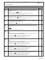
Table of Contents
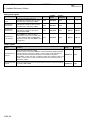
TABLE OF CONTENTS
1. Notes on Safety
1.1 Hardware
1.2 Software
1
2
3
2. Introduction
KSW-4
3. Selecting the Type of Reference
Value
KSW-5
4. Representing the Reference Values
in User Units
4.1 User Units with a Speed Reference
Value
4.2 User Units for a Torque Reference
Value
4.3 Switching between the Speed/Torque
Reference Value
4.4 Switching between Master/Slave Drive
in Speed/Speed Mode
4.5 Switching between Master/Slave Drive
in Torque/Speed Mode
5. Combining the Reference Values
5.1 Unchanged Main Reference Value
5.2 Main Reference Value + Absolute
Reference Value
5.3 Main Reference Value + Percental
Reference Value
5.4 Factor Reference Value (Weighting)
5.5 Switching the Main Reference Value
KSW-8
KSW-8
KSW-10
KSW-12
KSW-13
KSW-16
KSW-18
KSW-19
KSW-19
KSW-20
KSW-21
KSW-22
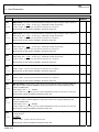
6. Available Reference Values
KSW-24
6.1 Reference Value External, Correction
Reference Value 1 and 2
KSW-24
6.2 Preset Values (Fixed Values) and
Preset Reference Values
KSW-26
6.2.1 Preset Reference Values
KSW-26
6.2.2 Preset Values
KSW-31
6.3 Motor Potentiometer
KSW-34
6.4 PID Controller
KSW-39
6.5 N-actual
KSW-46
7. Additional Functions
KSW-47
8. Parameterizing the Speed and
Torque Limits
8.1 Torque Limits
8.2 Speed Limits
KSW-53
KSW-53
KSW-57
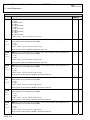
9. Additional Functions
9.1 Skipping Speed
9.2 Brake Activation
9.3 Range Control and Display Scaling
9.4 Reference Value Enable
9.5 Events
KSW-60
KSW-60
KSW-62
KSW-63
KSW-67
KSW-68
10. Fieldbus
KSW-69
11. Used Parameters
11.1 Parameter Legend
11.2 Parameter List
KSW-70
KSW-70
KSW-70
5th Generation of STÖBER Inverters
STÖBER
ANTRIEBSTECHNIK
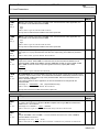
1. Notes on Safety
1
NOTES ON SAFETY
This manual contains information which must be adhered to in order to prevent personal
injury and property damage. This information is graduated by degree of damage as
shown below.
ATTENTION
Means that an undesired result or undesired state may occur if this note is not heeded.
CAUTION
Without warning triangle: Means that property damage may occur if appropriate
precautions are not taken.
CAUTION
With warning triangle: Means that minor personal injury and property damage may occur
if appropriate precautions are not taken.
WARNING
Means that major danger of death and substantial property damage may occur if
appropriate precautions are not taken.
DANGER
Means that great danger to life and substantial property damage will occur if appropriate
precautions are not taken.
NOTE
Indicates an important piece of information on the product or the drawing of attention to a
part of the documentation requiring special attention.
ACTION
Means the description of an action which is particularly important for handling the
product.
1
5th Generation of STÖBER Inverters
STÖBER
ANTRIEBSTECHNIK
1. Notes on Safety
1.1
Hardware
WARNING
To ensure that avoidable problems do not occur during commissioning and/or operation,
be sure to read these installation and commissioning instructions before installation and
commissioning.
In the sense of DIN EN 50178 (formerly VDE 0160), the FDS and MDS model series of
POSIDRIVE® are electrical components of power electronics for the regulation of energy
flow in high-voltage systems. They are exclusively designed to power servo (MDS) and
asynchronous (FDS, MDS) machines. Utilization, installation, operation and maintenance
are only permitted under observation and adherence to valid regulations and/or legal
requirements, applicable standards and this technical documentation.
This is a product of the restricted sales class in accordance with IEC 61800-3. In a
residential zone, this product may cause high-frequency interference in which case the
user may be requested to take suitable measures.
Strict adherence to all rules and regulations must be ensured by the user.
The safety notes contained in further sections (items) and specifications must be
adhered to by the user.
WARNING
Caution! High touch voltage! Danger of shock! Danger to life!
When network voltage is applied, never under any circumstances open the housing or
disconnect the connections. When installing or removing option boards, you may only
open the inverter in the dead state (all power plugs disconnected) and only after a
waiting period of at least 5 minutes after the network voltage is switched off. Prerequisite
for the correct functioning of the inverter is the correct configuration and installation of
the inverter drive. Transport, installation, commissioning and handling of the device may
only be performed by qualified personnel who have been especially trained for these
tasks.
Pay particular attention to the following:
• Permissible protection class: Protective ground. Operation is only permitted when the
protective conductor is connected in accordance with regulations. Direct operation of
the devices on IT networks is not possible.
• Installation work may only be performed in the dead state. For work on the drive, lock
enable and disconnect the complete drive from the power. (Observe the 5 safety
rules.)
• Leave the plug for the DC link coupling connected even when the DC link coupling is
not being used (BG0-BG2: X22)!
• Discharge time of the DC link capacitors > 5 minutes.
• Do not penetrate the device's interior with any kind of object.
• During installation or any other work in the switching cabinet, protect the device
against falling parts (pieces of wire, stranded wire, pieces of metal, and so on). Parts
with conductive properties may cause a short circuit within the inverter or device
failure.
• Before commissioning, remove extra coverings so that the device cannot overheat.
The inverter must be installed in a switching cabinet in which the maximum ambient
temperature (see technical data) is not exceeded. Only copper lines may be used. The
line cross sections to be used are contained in table 310-16 of the NEC standard at
o
o
60 C or 75 C.
The company STÖBER ANTRIEBSTECHNIK GmbH + Co. KG accepts no liability for
damages resulting from non-adherence to the instructions or the particular
regulations.
2
5th Generation of STÖBER Inverters
STÖBER
ANTRIEBSTECHNIK
1. Notes on Safety
The motor must have an integral temperature monitor with basis insulation as per
EN 61800-5-1 or external motor overload protection must be used.
Only suitable for use on supply current networks which cannot deliver more than a
maximum symmetric, nominal, short-circuit current of 5000 A at 480 Volt.
Subject to technical changes without prior notification which changes serve to
improve the devices. This documentation is purely a product description. It does
not represent promised properties in the sense of warranty law.
1.2
Software
Use of the POSITool software
The POSITool software package can be used to select an application, adjust parameters
and signal monitoring of the 5th generation of STÖBER inverters. The functionality is
specified by the selection of an application and the transmission of these data to an
inverter.
The program is the property of STÖBER ANTRIEBSTECHNIK GmbH + Co. KG and is
protected by copyright. The program is licensed for the user.
The software is provided exclusively in machine-readable format.
The customer receives from STÖBER ANTRIEBSTECHNIK GmbH + Co. KG a nonexclusive right to use the program (license) if the program was obtained legally.
The customer has the right to utilize the program for the above stated activities and
functions and to make and install copies of the program, including one backup copy, for
support of said utilization.
The conditions of this license apply to all copies. The customer is obligated to place the
copyright note and all other ownership notes on every copy of the program.
The customer is not authorized to use, copy, change or pass on/transmit the program for
reasons other than those covered by these conditions; the customer is also not
authorized to convert the program (reverse assembly, reverse compilation) or compile
the program in any other manner, or to sublicense, rent or lease the program.
Product maintenance
The obligation to perform maintenance applies to the two last current program versions
prepared and released for use by STÖBER ANTRIEBSTECHNIK GmbH + Co. KG.
STÖBER ANTRIEBSTECHNIK GmbH + Co. KG can either correct program errors or
provide a new program version. The choice is up to STÖBER ANTRIEBSTECHNIK
GmbH + Co. KG. If, in individual cases, the error cannot be corrected immediately,
STÖBER ANTRIEBSTECHNIK GmbH + Co. KG will provide an intermediate solution
which, if necessary, requires adherence by the user to special operating regulations.
The claim to error correction only exists when reported errors are reproducible or can be
recorded by machine-made outputs. Errors must be reported in reconstructable form
giving useful information for error correction.
The obligation to correct errors is invalidated for such programs which the customer
changes or manipulates unless the customer can prove when reporting the error that the
manipulation is not the cause of the error.
STÖBER ANTRIEBSTECHNIK GmbH + Co. KG is obligated to keep the currently valid
program versions in a specially protected place (fire-resistant data safe, safety deposit
box at a bank).
3
Comfort Reference Value – 5th Generation of STÖBER Inverters
STÖBER
ANTRIEBSTECHNIK
2. Introduction
2
INTRODUCTION
Introduction
The Comfort Reference Value application gives you a wide variety of functionalities for
speed and torque operation. You can select from the following available types of
reference values:
• Speed reference value
• Torque reference value
• Switch between speed and torque reference values during operation
• Switch between master/slave drive (i.e., the switch between an internal speed
reference value and the reference value of a master drive or in other words a master
reference value). The master can specify a speed or a torque reference value. The
internal reference value is always a speed reference value.
Reference value interfaces such as analog reference values, preset reference values or
motor potentiometers are available for the different types of reference values. In addition
you can use skip-speeds, comparators and other supplemental functions.
The Comfort Reference Value
Assistant
Since this description is based on the structure of the Comfort Reference Value
Assistant, STÖBER Antriebstechnik recommends studying the Assistant together with
this description for better comprehension.
To access the Assistant, open the Comfort Reference Value application in POSITool.
Input and output signals
You will find comprehensive information on input and output signals in the signal tables
at the end of some of the sections. The signal tables are organized as follows.
Binary input signals
In addition to the designation and a description the signal tables for binary inputs contain
the selection parameter (Selector) in which you can set the signal source. You can
choose between a binary input or fieldbus (setting 2:parameter). If you select fieldbus the
column Fieldbus Image shows you the address to which you write the signal.
The column Display Parameter shows you the signal status regardless of the source
which is set in the selector.
In addition a switch-on or switch-off delay can be parameterized for some of the binary
input signals. You will find the parameters in which the delay times are to be entered in
the column Time ON or Time OFF.
Analog input signals
In addition to the designation and description you will also find the specification of
Selector, Fieldbus Image and Display Parameter for analog input signals. You can
use the parameter specified as Fieldbus image to obtain a constant value during
operation. Set the Selector to 4:parameter and enter the desired value in this parameter.
The link to a fieldbus system is not necessary in this case.
In addition a characteristic curve scaling can be performed for some of the signals. You
will find the scaling parameters in the Scaling column. The applicable description
explains how to perform characteristic curve scaling.
Status signals
KSW-4
The designation and description are also to be found in the tables of the binary status
signals. The column Fieldbus Image shows the address from which the signal can be
read via fieldbus. The column Single Parameter gives you the parameter to be used to
indicate the signal on a binary output.
Comfort Reference Value – 5th Generation of STÖBER Inverters
STÖBER
ANTRIEBSTECHNIK
3. Selecting the Type of Reference Value
3
SELECTING THE TYPE OF REFERENCE VALUE
Information that you will find in
this chapter …
This chapter gives you information on:
• what a reference value is and the types of reference values which are provided by the
Comfort Reference Value application
• how to select the type of reference value and
• further details for the types of reference values are present
Types of reference values
The type of motor control is called the type of reference value. The Comfort Reference
Value application offers you a choice of the following types of reference values.
• Speed reference value (i.e., control of the motor speed). A speed reference value is
used for belt drives, pumps and fans, for example.
• Torque reference value (i.e., control of the torque). A torque reference value is used
for insertion and for screw driving, for example.
• Switching between speed and torque reference value (i.e., switching between speed
and torque control during operation). Switching between controls is used for pressure
rollers, for example.
• Switching between master/slave drive (i.e., switching from an internal reference value
to a master reference value). The internal reference value is always used as speed
reference value. The external reference value can be used as the torque or speed
reference value. This type of reference value is used, for example, for a multiple-axis
network with slaves which can be turned off.
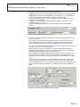
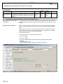
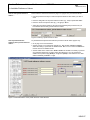
How to select the type of
reference value …
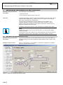
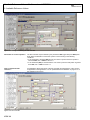
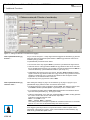
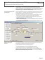
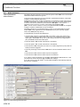
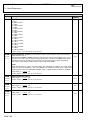
The type of reference value is selected on page 1 of the Comfort Reference Value
Assistant (see Figure 3-1). You can activate a type of reference value by activating the
related option box.
Figure 3-1 Comfort Reference Value Assistant (page 1): Selection of the type of reference value
KSW-5
Comfort Reference Value – 5th Generation of STÖBER Inverters
STÖBER
ANTRIEBSTECHNIK
3. Selecting the Type of Reference Value
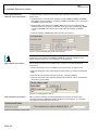
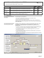
How to switch between speed
and torque reference values
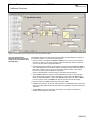
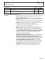
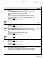
If you choose to switch controls during operation, page 1 of the Assistant indicates the
parameter D112 (Figure 3-2). In Selector D112 select a signal source (binary input or
fieldbus parameter). You can then switch between the types of control during operation
with this signal. Speed control is used for a low level while torque control is used for a
high level.
Figure 3-2 Setting for the speed/torque reference value switchover
KSW-6
STÖBER
Comfort Reference Value – 5th Generation of STÖBER Inverters
ANTRIEBSTECHNIK
3. Selecting the Type of Reference Value
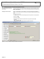
How to switch between
master/slave drive
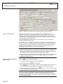
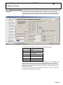
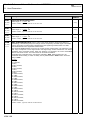
If you use the switchover between master and slave drive, the parameter D111 and
additional option boxes appear (Figure 3-3). Select a signal source in this parameter
(binary input or fieldbus parameter). You can then switch between master and slave
during operation with this signal. The internal speed reference value is used for a low
level. With a high level the drive uses the master reference value.
With the other option boxes you can choose a speed/speed or torque/speed switchover.
If you use the torque/speed switchover the master reference value is evaluated as the
torque reference value.
Figure 3-3 Setting for the master/slave drive switchover
Details
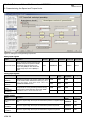
Page 1 of the Comfort Reference Value Assistant affects the parameter C61. This
parameter is used to specify whether speed or torque control will be used.
With a speed reference value, C61 is set to 0:inactive. With a torque reference value,
C61 is set to 1:active.
When switching between speed and torque control is used the switch is made with the
signal selected in D112.
When the type "master/slave drive" reference value is used with the switchover
speed/speed, C61 is set to 0:inactive. With the speed/torque switchover, C61 is set to
1:active. The specification of whether torque control or speed control is to be used is
made with the signal selected in D111. Speed control is used with a low level while
torque control is used with a high level.
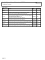
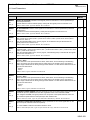
Signal
Function
Master/slave
switchover
With a high level, a switch is made to the
D111
master reference value (D140).
Binary signal for switching between
speed and torque control. Speed control
D112
is used with a low level. Torque control
is active with a high level.
Speed/torque
switchover
Selector
Fieldbus
Image
Display
Parameter
Time ON
Time OFF
D210 Bit11
D311
D411.0
D411.1
D210 Bit12
D312
D412.0
D412.1
Table 3-1 Signal table for selection of the type of reference value
KSW-7
Comfort Reference Value – 5th Generation of STÖBER Inverters
STÖBER
ANTRIEBSTECHNIK
4. Representing the Reference Values in User Units
4
REPRESENTING THE REFERENCE VALUES IN USER UNITS
Information that you will find in
this chapter …
This chapter gives you information on:
• what user units are
• how to scale your reference value in user units
User units
To simplify presentation, reference values can be indicated in user units in the Comfort
Reference Value application (e.g., bottles per second on a bottle conveyor belt). All
ratios of the motor speed are covered by this.
The user units are calculated in the Comfort Reference Value Assistant. Since
calculation depends on the type of reference value used, go to page "1. Type of
Reference Value" first and select one of the options offered there. After that you can
perform the calculation on the next page.
Calculation of each type of reference value is described in a separate section below.
NOTE
Remember that scaling only has to be performed when you want to present display
values in user units.
If presentation in rpm units is sufficient, the scaling described in the next few sections is
unnecessary. If this is the case, skip chapter 4 and continue reading in chapter 5.
4.1
User Units with a Speed Reference Value
Information that you will find in
this section …
This section describes how to scale a speed reference value in user units. Before you
can begin scaling you must have activated the speed reference value on page 1 of the
Assistant.
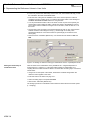
Scaling the reference value
Figure 4-1 shows page 2.1 of the Assistant. It presents the organization of a machine
with motor, gear unit and other ratios.
Figure 4-1 Scaling for the speed-type reference value
KSW-8
Comfort Reference Value – 5th Generation of STÖBER Inverters
STÖBER
ANTRIEBSTECHNIK
4. Representing the Reference Values in User Units
First, edit the parameters on the top of the page (Figure 4-2):
• In D86 specify the number of decimal digits with which speeds are to be represented.
• In D89 enter the desired unit of measurement for the speed (e.g., compartments per
second). Remember that not more than 8 characters can be entered.
• Activate the option box as per your entry in D89 so that the time reference can be
correctly calculated internally.
Example: You have entered compartments/second in D89. In this case you would
activate the option box "/sec."
• Enter the rated speed of the machine in D56 (necessary for percental reference
values).
Figure 4-2 Parameters for scaling in user units
You can now enter the gear ratios within the lower range of the page (Figure 4-3). There
are two ways to do this:
1. You already know the mathematical relationship between the speed of the motor in
rpm and the speed of the machine in user units. If this is the case, enter the ratio
directly in D87 numerator (machine speed) and D88 denominator (motor speed).
2. You do not yet know the relationship. If this is the case, the Assistant will help you with
the calculation. Proceed as described below:
• Enter the ratio of the gear unit installed on the motor. Enter as precise a value as
possible to prevent rounding errors. You will find the precise ratios in the catalogs for
STÖBER ANTRIEBSTECHNIK GmbH+Co. KG gear units.
• You can parameterize another ratio in the boxes n3 and n4 (ratio of the speeds), Z3
and Z4 (ratio of the numbers of teeth) or D3 and D4 (ratio of the diameters). If there
are no further ratios in addition to the gear unit on the motor, enter the ratio 1:1 in the
boxes.
• The last step is the conversion of the speed after the last ratio in user units has been
entered. Enter the format length in mm (e.g., the format length of one bottle). Then
parameterize either D4 or the feed constant Cv (distance/revolution of the driven gear).
• Press the button “Calculate” (Berechnen). You will then find the results in D87 und
D88.
Figure 4-3 Conversion of motor speed to machine speed
KSW-9
Comfort Reference Value – 5th Generation of STÖBER Inverters
STÖBER
ANTRIEBSTECHNIK
4. Representing the Reference Values in User Units
4.2
User Units for a Torque Reference Value
Information that you will find in
this section …
This section describes how to scale a torque reference value in user units. Before you
can begin scaling you must have activated the torque reference value on page 1 of the
Assistant.
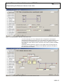
Scaling the reference value
Figure 4-4 shows page 2.2 of the Assistant. It presents the structure of a machine with
motor, gear unit and other ratios.
force
torque
Figure 4-4 Scaling in the torque-type reference value
First, edit the parameters on the top of the page (Figure 4-5):
• In D86 specify the number of decimal digits with which torques are to be represented.
• In D89 enter the desired unit of measurement for the torque or the force (e.g., in %).
Remember that not more than 8 characters can be entered.
• Enter the rated torque of the machine in D56.
Figure 4-5 Parameter D86, D89 and D56
KSW-10
Comfort Reference Value – 5th Generation of STÖBER Inverters
STÖBER
ANTRIEBSTECHNIK
4. Representing the Reference Values in User Units
You can now enter the gear ratios within the lower range of the page (Figure 4-6). There
are two ways to do this:
1. You already know the mathematical relationship between the torque of the motor and
the machine in user units. If this is the case, enter the ratio directly in D87 numerator
(torque on output) and D88 denominator (motor torque).
2. You do not yet know the relationship. If this is the case, the Assistant will help you with
the calculation. Proceed as described below:
• Enter the ratio of the gear unit installed on the motor and degree of efficiency. Enter as
precise a value as possible to prevent rounding errors. You will find the precise ratios
in the catalogs for STÖBER ANTRIEBSTECHNIK GmbH+Co. KG gear units.
• You can parameterize another ratio in the boxes n3 and n4 (ratio of the speeds), Z3
and Z4 (ratio of the numbers of teeth) or D3 and D4 (ratio of the diameters). Also enter
a degree of efficiency for this ratio. If there are no further ratios in addition to the gear
unit on the motor, enter the ratio as 1:1 and the degree of efficiency as 1 in the boxes.
• The last step is the conversion of the torques after the last ratio in user units has been
entered. Click either the “Force” (Kraft) box or the “Torque” (Drehmoment) box. Then
enter the conversion factor between force or torque and the user unit in the input
fields.
Example:
3.5 Nm corresponds to one user unit.
In this case click the “Torque” (Drehmoment) box and enter the factor 3.5 in the input
field.
• Press the button “Calculate” (Berechnen). You will then find the results in D87 und
D88.
Figure 4-6 Calculation of the ratio
KSW-11
Comfort Reference Value – 5th Generation of STÖBER Inverters
STÖBER
ANTRIEBSTECHNIK
4. Representing the Reference Values in User Units
4.3
Switching between the Speed/Torque Reference Value
Information that you will find in
this section …
This section explains how to scale reference values after you have activated the switch
between speed and torque reference value (Umschaltung Drehzahl-/Momentsollwert) on
page 1 of the Assistant.
Scaling the reference value
Figure 4-7 shows page 2.3 of the Assistant. You can only scale this type of reference
value in % which means that you don't need to do extensive scaling for speed and torque
mode.
Proceed as shown below:
• In D86 specify the number of decimal digits with which speeds are to be represented.
• Enter "%" in D89.
• Enter 100% in D56.
• Enter a percentage in D87 and parameterize the appropriate speed in D88.
Example:
D87= 50%, D88 = 1000
This gives you a reference value of 50% of a speed of 1000 Rpm.
Figure 4-7 Scaling for reference value type "speed/torque switchover"
KSW-12
Comfort Reference Value – 5th Generation of STÖBER Inverters
STÖBER
ANTRIEBSTECHNIK
4. Representing the Reference Values in User Units
4.4
Switching between Master/Slave Drive in Speed/Speed Mode
Information that you will find in
this section …
This section explains how to scale the reference values in user units with a master/slave
drive with speed/speed switchover. Before you can begin scaling you must have
activated "switch master/slave drive" with “speed/speed switchover” (Umschaltung
Drehzahl/Drehzahl) on page 1 of the Assistant.
Scaling the reference value
Figure 4-8 shows page 2.4 of the Assistant. It presents the structure of a machine with
motor, gear unit and other ratios.
Figure 4-8 Scaling for reference value type "master/slave drive" in "speed/speed" mode
First, edit the parameters on the top of the page (Figure 4-9):
• In D86 specify the number of decimal digits with which speeds are to be represented.
• In D89 enter the desired unit of measurement for the speed (e.g., compartments per
second). Remember that not more than 8 characters can be entered.
• Activate the option box as per your entry in D89 so that the time reference can be
correctly calculated internally.
Example: You have entered compartments/second in D89. In this case you would
activate the option box "/sec" as the time reference.
• Enter the rated speed of the machine in D56.
Figure 4-9 Parameter D86, D89 and D56
You can now enter the gear ratios within the lower range of the page (Figure 4-10).
There are two ways to do this:
1. You already know the mathematical relationship between the speed of the motor in
rpm and the speed of the machine in user units. If this is the case, enter the ratio
directly in D87 numerator (machine speed) and D88 denominator (motor speed).
KSW-13
Comfort Reference Value – 5th Generation of STÖBER Inverters
STÖBER
ANTRIEBSTECHNIK
4. Representing the Reference Values in User Units
2. You do not yet know the relationship. If this is the case, the Assistant will help you with
the calculation. Proceed as described below:
• Enter the ratio of the gear unit installed on the motor. Enter as precise a value as
possible to prevent rounding errors. You will find the precise ratios in the catalogs for
STÖBER ANTRIEBSTECHNIK GmbH+Co. KG gear units.
• You can parameterize another ratio in the boxes n3 and n4 (ratio of the speeds), Z3
and Z4 (ratio of the numbers of teeth) or D3 and D4 (ratio of the diameters). If there
are no further ratios in addition to the gear unit on the motor, enter the ratio as 1:1 in
the boxes.
• The last step is the conversion of the speed after the last ratio in user units has been
entered. Enter the format length in mm (e.g., format length of a bottle). Then
parameterize either D4 or the feed constant Cv (feed length per revolution of the
driven gear).
• Press the button “Calculate” (Berechnen). You will then find the results in D87 und
D88.
Figure 4-10 Scaling for reference value type "master/slave drive" in "speed/speed" mode
Setting the relationship of
master/slave drive
Click the “Ratio of the master/slave drive” (Verhältnis Leit- / Folgeantrieb) button to
access page 2.4.1 (Figure 4-11). This page makes it easier to parameterize a 1:1
coupling when the master reference value is connected with an analog input. Proceed as
shown below:
• Using a test for the speed of the master, determine the related voltage which the
reference value supplies to the slave.
• Enter this value in the first line of page 2.4.1.
• Select an analog input in the parameter D140.
• Click the box “Calculate” (Berechnen).
The analog input factor is calculated so that master and slave travel at the same speed
(1:1 coupling).
KSW-14
Comfort Reference Value – 5th Generation of STÖBER Inverters
STÖBER
ANTRIEBSTECHNIK
4. Representing the Reference Values in User Units
Figure 4-11 Parameterization of the ratio "master/slave drive"
You can access page 2.4.1.A by clicking the button “Configuration of analog input”
(Konfiguration Analogeingang) (Figure 4-12). The interface of the master reference value
is parameterized on this page if the master reference value is supplied via an analog
input. When the master reference value is entered on the inverter by fieldbus, set D140 =
4:parameter.
Remember that the information in Figure 4-12 only applies when the analog input has
been selected. For details on the settings see the applicable parameter descriptions in
the bottom half of the Assistant.
Figure 4-12 Parameterization of the signal source for the master reference value
KSW-15
STÖBER
Comfort Reference Value – 5th Generation of STÖBER Inverters
ANTRIEBSTECHNIK
4. Representing the Reference Values in User Units
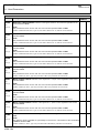
Analog signals
Signal
Function
Selector
Fieldbus
Image
Display
Parameter
Master reference
value
The master reference value signal can be accessed
via analog input or fieldbus. This signal can be used
to implement a master-slave operation via an analog
coupling.
D140
D240
D340
4.5
Scaling
-
Switching between Master/Slave Drive in Torque/Speed Mode
Information that you will find in
this section …
This section shows you how to scale a torque reference value in user units. Before you
can begin scaling you must have activated the torque reference value on page 1 of the
Assistant.
Scaling the reference value
Figure 4-13 shows page 2.5 of the Assistant. You can only scale this type of reference
value in % which means you don't need to do extensive scaling for speed and torque
mode.
With asynchronous motors a 100% torque reference value corresponds to the rated
torque. With servomotors a 100% torque reference value corresponds to the standstill
torque. Scaling of the speed is done in D87 and D88.
Proceed as shown below:
• Specify the accuracy of the representation in D86.
• Enter "%" in D89.
• Enter 100% in D56.
• Enter a percentage in D87 and parameterize the appropriate speed in D88.
Example:
D87= 50%, D88 = 1000
This gives you at reference value of 50% a speed of 1000 Rpm.
Figure 4-13 Scaling for reference value type "master/slave drive" in "speed/torque" mode
KSW-16
Comfort Reference Value – 5th Generation of STÖBER Inverters
STÖBER
ANTRIEBSTECHNIK
4. Representing the Reference Values in User Units
Setting the relationship of
master/slave drive
Click the “Ratio of the master/slave drive” (Verhältnis Leit- / Folgeantrieb) button to
access page 2.5.1 (Figure 4-14). This page makes it easier to parameterize a 1:1
coupling when the master reference value is connected via an analog input. Proceed as
shown below:
• Using a test for a torque of the master, determine the related voltage which the
reference value supplies to the slave.
• Enter this value in the first line of page 2.5.1.
• In the second line parameterize the torque which the slave is to provide at 10 V of the
master reference value.
• Select an analog input in the parameter D140.
• Click the box “Calculate” (Berechnen).
The analog input factor is calculated so that master and slave provide the same torque
(1:1 coupling).
Figure 4-14 Parameterization of the ratio "master/slave drive"
Click the button “configuration of analog input” (Konfiguration Analogeingang) to access
page 2.4.1.A (Figure 4-12). You can use this page to parameterize the interface of the
master reference value when the master reference value is provided via an analog input.
You don't have to edit this page if the master reference value is transferred to the
inverter via fieldbus.
Remember that the information in Figure 4-12 only applies when the analog input has
been selected. For details on the settings see the applicable parameter descriptions
within the lower range of the Assistant.
KSW-17
Comfort Reference Value – 5th Generation of STÖBER Inverters
STÖBER
ANTRIEBSTECHNIK
5. Combining the Reference Values
5
COMBINING THE REFERENCE VALUES
Information that you will find in
this chapter …
This chapter gives you information on:
• just what the combination of reference values is
• which combinations are provided by the Comfort Reference Value application
• and how to parameterize the combinations
Reference value combination
After you have parameterized a reference value type and done any desired scaling as
described in the previous sections, you can now begin combining the reference values.
Reference value combination means the mathematical linking of different reference
values (e.g., the addition of an analog reference value and a preset reference value).
The result is evaluated as per the select type of reference value (e.g., as torque
reference value).
The following combinations are available:
• Main reference value (unchanged)
• Main reference value + absolute reference value
• Main reference value + percental reference value
• Weighting of the combinations
The following sections describe how to parameterize the specified combinations. Page 3
of the "Comfort Reference Value" Assistant handles the parameterization (Figure 5-1).
Figure 5-1 Reference value combination
NOTE
The described combinations only apply to the reference value. The ramps of the main
reference value are used unchanged in the ramp generator.
KSW-18
STÖBER
Comfort Reference Value – 5th Generation of STÖBER Inverters
ANTRIEBSTECHNIK
5. Combining the Reference Values
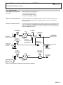
5.1
Unchanged Main Reference Value
Information that you will find in
this section …
This section shows you how to parameterize a main reference value which cannot be
influenced by addition of or multiplication by any other reference value.
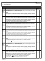
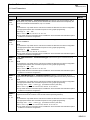
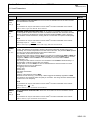
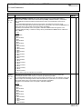
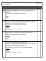
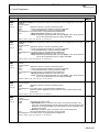
Unchanged main reference value
Proceed as shown below to parameterize an unchanged main reference value:
• Select a reference value source in D30 (e.g., D30=3:Motorpot).
• Set D31 and D33 to "0:inactive."
The selected main reference value is transmitted unchanged with this parameterization.
Display parameters D381 and D382 indicate the same value.
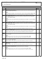
Main reference
value source Selected main
ref. value
D30
Ref. val. ext.
0
Preset RVs
1
CorrectionRV1 2
n-actual
Ref. val.
after
addition
D381
Factor
ref. val.
source
D33=0
D382
+
Additive
ref. val.
source
6
+
D31=0
Figure 5-2 Unchanged main reference value
5.2
Main Reference Value + Absolute Reference Value
Information that you will find in
this section …
This section shows you how to parameterize a reference value which consists additively
of two components.
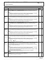
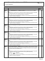
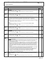
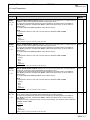
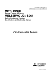
Main reference value + absolute
reference value
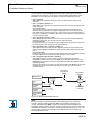
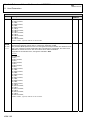
Proceed as shown below to parameterize an absolute addition of two reference values
(see Figure 5-3):
• Select the desired reference value sources in D30 and D31 (e.g., D30=0:reference
value external and D31=2:preset value).
• Parameterize the value 0: absolute in D32 so that absolute addition will be performed.
• Set D33=0:inactive.
With this parameterization, the reference values set in D30 and D31 are added. D381
shows the value of the main reference value and D382 shows the result of the addition.
Example:
The reference value set in D30 supplies the value 500 Rpm and the value selected in
D31 supplies 250 Rpm. The total result is: 500 Rpm + 250 Rpm = 750 Rpm. 500 Rpm is
indicated in D381 and 750 Rpm is indicated in D382.
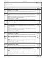
Ref. val. ext.
Preset RVs
Corr. RV1
n-actual
Main ref. val.
source Selected main
ref. value
D30
0
D381
1
+
0
1
6
Additive ref. val.
source
Inactive
0
Ref. val. ext. 1
Preset ref. val. 2
Fix value
Additive
ref. val.
mode
D32=0
D382
+
2
Ref. va.
after
addition
D31
D33=0
Factor
ref. val.
source
7
Figure 5-3 Main reference value + absolute reference value
KSW-19
STÖBER
Comfort Reference Value – 5th Generation of STÖBER Inverters
ANTRIEBSTECHNIK
5. Combining the Reference Values
5.3
Main Reference Value + Percental Reference Value
Information that you will find in
this section …
This section shows you how to parameterize an additive reference value consisting of
two components. One component references the first component as a percentage.
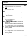
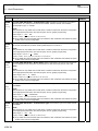
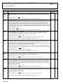
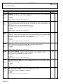
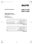
Main reference value + percental
reference value
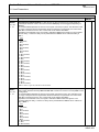
To parameterize this combination proceed as shown below:
• Select the desired reference value sources in D30 and D31 (e.g., D30=0:reference
value and D31=2:preset reference value.
• Set D32 to "1:percental"
• Set D33=0:inactive.
With this parameterization, the reference value selected in D31 is related to D56. The
resulting percentage is multiplied by the main reference value and the result is added to
the main reference value (see Figure 5-4).
Example:
The main reference value is 1000 rpm which is indicated in D381. The additive reference
value supplies the value 500 rpm. The value 2000 is entered in D56.
The additive reference value as related to D56 supplies the result 500 rpm / 2000 rpm =
¼. This results in the total result of 1000 rpm + 1000 rpm x ¼ =1250 rpm. This value is
indicated in D382.
Ref. val. ext.
0
Preset RVs
1
Correction RV12
n-actual
Additive
ref. val.
mode
Main
ref. val.
source
Selected
D30 main ref. val.
D32=1
D382
0
D381
+
1
+
6
Additive ref. val.
source
D31
Inactive
Ref. val. ext.
Preset RVs
Fix value
0
1
2
7
Rated unit D56
speed
1
X
Figure 5-4 Main reference value + percental reference value
KSW-20
Ref. val.
after
addition
Factor
ref. val.
source
D33=0
STÖBER
Comfort Reference Value – 5th Generation of STÖBER Inverters
ANTRIEBSTECHNIK
5. Combining the Reference Values
5.4
Factor Reference Value (Weighting)
Information that you will find in
this section …
This section shows you how to weight one of the combinations described in chapter 5.1,
5.2, or 5.3 with a factor.
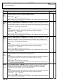
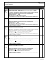
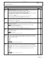
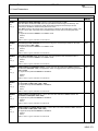
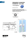
Weighting with the factor
reference value
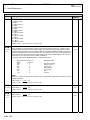
To set up weighting proceed as shown below:
• Set one of the combinations described in chap. 5.1, 5.2 or 5.3.
• Select a reference value source in D33 (e.g., "5:correction ref 2").
The reference value is related to D56 and multiplied by the result of the addition of main
reference value and additive reference value (see Figure 5-5).
Example:
The sum of main reference value and additive reference value results in the value 1500
rpm (D382). 3000 rpm is entered in D56. The reference value selected in D33 has the
value 1000 rpm.
The result is calculated as follows:
1500 rpm x 1000 rpm / 3000 rpm = 1500 rpm x 1/3 = 500 rpm
This value is indicated in D383.
Inactive
Ref. val. ext.
Preset RVs
Preset (fixed) value
Rated unit
speed
0
Main ref. value
and
additive ref. val.
Factor
ref. val.
source
D33
D382
1
Ref. val.
after
addition
2
D383
7
D56
Ref. value
after factor
1
X
Figure 5-5 Weighting by multiplicative reference value
KSW-21
STÖBER
Comfort Reference Value – 5th Generation of STÖBER Inverters
ANTRIEBSTECHNIK
5. Combining the Reference Values
5.5
Switching the Main Reference Value
Information that you will find in
this section …
This section shows you how to switch the main reference value selected in D30 during
operation (e.g., from reference value external to motor potentiometer).
Switching the main
reference value
Use the uppermost arrow on the left side of Assistant page 4 to access the parameters
to set up the switchover. This arrow takes you to page 3.8 entitled "main reference value
selector" (see Figure 5-6).
Figure 5-6 Parameterization of the selectors for the selection of the main reference value
The signals main ref select 0 to 2 are used for the switchover. One of the selections from
D30 is selected by the binary coding of the signals. You set the sources of these signals
with selectors D118.0 to D118.2. The following table shows which signal states of the
sources selected in D118.x can be used to achieve the respective reference values.
Remember that the reference value 0 rpm is specified with selection 7.
In D118.2 selected
source
In D118.2 selected
source
In D118.2 selected
source
0
0
0
0:RV external
0
0
1
1:Preset value
0
1
0
2:Correct ref1
0
1
1
3:Motorised pot
1
0
0
4:Correct ref2
1
0
1
5:PID
1
1
0
6:n-actual
1
1
1
–
Ref. value in D30
The switchover must be confirmed by an enable signal to ensure that no undesired
states occur during the switchover. The enable signal can be edge or level-controlled.
Select a source in D119 for an edge-controlled signal. Set a source in D120 for a levelcontrolled enable.
KSW-22
STÖBER
Comfort Reference Value – 5th Generation of STÖBER Inverters
ANTRIEBSTECHNIK
5. Combining the Reference Values
Binary inputs
Signal
Function
Main reference
value select 0
The main reference value select signals
can be used to switch between different D118.0
main reference value sources during
operation (e.g., reference value external,
D118.1
correction reference value or motor
potentiometer). The selection with the
main reference value selectors takes
D118.2
priority over the setting in D30.
Main reference
value select 1
Main reference
value select 2
Enable main
reference value
(edge)
Enable main
reference value
(level)
When the main reference value is
switched during operation, the change
must be accepted with an enable signal.
The enable can be edge or levelcontrolled. To accept a switchover the
enable main reference value (edge)
signal must have a positive edge or the
enable main reference value (level)
signal must have a HIGH level.
Selector
Fieldbus
Image
Display
Parameter
D211 Bit7
D211 Bit8
D318
D211 Bit9
Time ON
Time OFF
-
-
-
-
-
-
D119
D211 Bit10
D319
D419.0
D419.1
D120
D211 Bit11
D320
D420.0
D420.1
KSW-23
STÖBER
Comfort Reference Value – 5th Generation of STÖBER Inverters
ANTRIEBSTECHNIK
6. Available Reference Values
6
AVAILABLE REFERENCE VALUES
Information that you will find in
this chapter ...
This chapter gives you information on:
• the functions of the reference values that you can set as main reference value, additive
reference value and weighting factor
• when to use them
• and how to parameterize the functions.
To access the reference values, call the applicable page of the Assistant or go to page 4
and use the arrow keys to the left of parameters D30, D31 and D33.
6.1
Reference Value External, Correction Reference Value 1 and 2
Information that you will find in
this section ...
This section shows you:
• the conditions under which to use the reference values "reference value external,
correction reference value 1, and correction reference value 2"
• how the reference values are set up
• and how to parameterize the reference values.
When to use the reference
values …
Use the reference values if you want to constantly change the reference values (e.g., via
a potentiometer or via the analog output group of a PLC). The reference value can also
be transferred via fieldbus.
Structure
Figure 6-1 shows the structure of the functions "reference value external, and correction
reference values 1 and 2." The table at the end of the section lists the related parameters
for each reference value.
Selector
AE1
AE2
AE3
Fieldbus
parameter
Monitoring
parameter
D52.X
D54.X
n
SW
D53.X
To the reference
value selectors
D30, D31 + D33
D51.X
Figure 6-1 Structure of reference value external and correction reference values
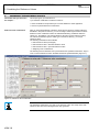
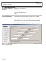
How to parameterize the
reference values ...
KSW-24
To parameterize a reference value, proceed as shown below:
• The source of the reference value signal can be set in the selector. You can supply the
reference value external and the correction reference values 1 and 2 via fieldbus or
analog input. Figure 6-2 shows page 3.1 of the Assistant for scaling the reference
value external. In our example analog input 1 (AE1) is set in D132 as the interface. All
parameters which you can use to modify the analog signal are listed. With fieldbus the
selection 4:parameter is made in the selector. The reference value is written via
fieldbus to the fieldbus parameter.
STÖBER
Comfort Reference Value – 5th Generation of STÖBER Inverters
ANTRIEBSTECHNIK
6. Available Reference Values
Figure 6-2 Parameterization of the signal source for reference value external
Characteristic curve scaling
• Use the array parameters D51.X to D54.X to scale the characteristic curve. The
characteristic curve links the selected input area with the set reference value area in
user units.
Example of reference value external:
D51.0 = 0.5 V, D52.0 = 8 V
D53.0 = 100 Rpm, D54.0 = 1500 Rpm
This setting means that 100 Rpm is specified when the reference value is 0.5 V and
1500 Rpm is specified when the reference value is 8 V. The characteristic curve is
calculated linearly between these two points.
• The ramps for the reference values can be parameterized in D82 and D83. You can
set the ramps on page 4 of the Assistant.
In online mode you can view the current value of the reference value regardless of the
source set in the monitoring parameter.
Analog signals
Signal
Function
Reference value
external
Correction
reference value 1
Correction
reference value 2
Analog reference value signals
Selector
Fieldbus
Image
Display
Parameter
Scaling
D132
D232
D332
D51.0 to
D54.0
D133
D233
D333
D51.1 to
D54.1
D134
D234
D334
D51.2 to
D54.2
KSW-25
Comfort Reference Value – 5th Generation of STÖBER Inverters
STÖBER
ANTRIEBSTECHNIK
6. Available Reference Values
6.2
Preset Values (Fixed Values) and Preset Reference Values
Information that you will find in
this section …
This section shows you:
• what preset reference values and preset values are
• the conditions under which preset reference values and preset values can be used
• how to define preset reference values and preset values
• and how to address preset reference values and preset values.
Description
When a preset reference value or a preset value is used a fixed value is output. The
speed is changed by switching between different preset values.
A ramp block can be set for a preset reference value. In contrast to the preset reference
value a preset value has no ramps. This is why the preset value can only be used as an
additive and factor reference value.
Up to 16 preset reference values and 8 preset values are available. Selection is binarycoded via binary inputs or bits in a control word (via fieldbus).
When you select the preset reference values via binary inputs 16 preset reference values
and 8 preset values are available. When fieldbus is used eight preset reference values
and eight preset values can be accessed at the same time. If you don't use preset values
via fieldbus, 16 preset reference values are also accessible.
When to use preset reference
values and preset values …
Preset reference values and preset values are used when you need to switch between a
maximum of 16 reference values which do not change. An example is the 3-stage setting
of a pump.
6.2.1 Preset Reference Values
Preset reference values
Preset reference values and ramp blocks are entered on page 3.4.1 of the Assistant
(Figure 6-3). Selection via binary signals is parameterized on page 3.4.2. Display
Parameters are available on page 3.4.3 for online monitoring.
Figure 6-3 Parameterization of the preset reference values
KSW-26
Comfort Reference Value – 5th Generation of STÖBER Inverters
STÖBER
ANTRIEBSTECHNIK
6. Available Reference Values
How to enter preset reference
values …
Preset reference values are entered on page 3.4.1 (Figure 6-4). Proceed as follows:
• Use the up/down arrow keys to select the preset reference value which you want to
enter.
• Enter the designation of the preset reference value (e.g., feed) in parameter D10.x.
• Enter the value of the preset value (e.g., 100 [rpm] in D11.x.
• Select the next preset reference value and keep repeating the procedure until you
have defined all necessary preset reference values.
Figure 6-4 Setting a preset reference value
How to parameterize the
selection of the preset reference
values …
To parameterize the preset value selection proceed as shown below (Figure 6-5):
• Go to page 3.4.2 of the Assistant.
• Set the sources of your switchover signals (e.g., BE1 to BE3) in D124.0 to D124.2.
Select the setting 2: parameter for fieldbus mode. Bits 0 to 3 of control word D212 are
used as sources for fieldbus mode.
• Set the enable of the switchover in D128 or D129. The enable is necessary to prevent
any undesired states from occurring during the switchover. You can activate the
enable with a positive edge (D128) or a high level (D129). If the switchover is to take
effect immediately set D129 = 1:High.
Figure 6-5 Parameterization of the preset reference value selectors
KSW-27
Comfort Reference Value – 5th Generation of STÖBER Inverters
STÖBER
ANTRIEBSTECHNIK
6. Available Reference Values
Example
Eight preset reference values are to be used. The binary inputs BE1, BE2 and BE3 are
to be used as sources for the "preset reference source" signals 0 to 2. The array
parameters D124.X are set to:
• D124.0 = 3:BE1
• D124.1 = 5:BE2
• D124.2 = 7:BE3
The preset reference value 6 is selected (110 binary=6 dec) with the signal state of:
BE3
BE2
BE1
1
1
0
The value in D11.6 is the preset reference value.
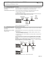
How to link preset reference
values and ramps …
There are several ways to link the 16 preset reference values with the 16 ramp blocks.
You can select one of the methods in parameter D13 on page 3.4.1 of the Assistant
(Figure 6-6).
Figure 6-6 Link of preset reference values and ramps
• D13 = 0:preset value
Preset reference values and ramp profiles of the same parameter element are coupled
with the setting "0:preset value." This means that preset reference value 0 (D10.0,
D11.0) is used with the settings of ramp profile 0 (D20.0 to D25.0), preset reference
value 1 (D10.1, D11.1) with ramp profile 1 (D20.1 to D25.1), and so on.
• D13 = 1:ramp profile
This setting allows you to enter the number of a ramp profile in parameter D12.X for
the coupling of preset reference value and ramp profile.
Example: D12.3 = 0 means that preset reference value 3 (D11.3) is used with ramp
profile 0. This setting makes it possible to configure several preset reference values
with one ramp profile.
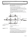
• D13= 2:binary signals
Deceleration and acceleration ramps are assigned to the preset reference value
independently of each other with this setting. Parameter D21.x has no function so that
you cannot set a symmetric ramp for direction to the right and direction to the left.
Allocation is binary-coded. The signal sources are selected with selectors D126.X for
accelerations and D127.X deceleration ramps. Binary inputs or a fieldbus parameter
can be selected. When fieldbus is used the signal source is provided by parameter
D210 with bit 4 to bit 7 for accelerations and bit 8 to bit 11 for deceleration ramps.
Figure 6-7 shows the relationship for the acceleration ramps. To keep things simple an
example is shown in which a choice of four acceleration ramps is available.
The signal sources for the preset reference value accelerating source select 0 and
preset reference value accelerating source select 1 are set in parameters D126.0 and
D126.1. These signals are used for the binary-coded selection of one of the ramp
profiles 0 to 3. The parameters D22.X and D24.X are important for the selection of the
accelerations in the ramp profile. Depending on the current direction of rotation D22.X
is used for direction to the right and D24.X for direction to the left.
KSW-28
STÖBER
Comfort Reference Value – 5th Generation of STÖBER Inverters
ANTRIEBSTECHNIK
6. Available Reference Values
PRV accelerating source select 0
(Selector D126.0)
Decode
PRV accelerating source select 1
(Selector D126.1)
Dir. right/
direction left
D22.0
D24.0
D22.1
D24.1
D22.2
D24.2
D22.3
D24.3
0
1
0
0
1
1
Current
accelerating
ramp
0
1
2
0
1
3
Figure 6-7 Ramp selection in mode D13 = 2: binary signal
How to enter ramp blocks …
Enter the ramps on page 3.4.1 as shown below (Figure 6-8):
• Go to page 3.4.1 of the Assistant.
• Use the up/down arrow keys to select the ramp block that you want to enter.
• Enter the designation of the ramp block (e.g., ramp feed) in parameter D20.x. Enter in
D21.x whether you want symmetric or asymmetric ramps for right or left direction.
When D21.X is set to 1:active the acceleration ramp is specified in D22.x and the
deceleration ramp is specified in D23.x for both directions of rotation. When
D21.x=0:inactive, D22.x and D23.x apply to the right direction. D24.x and D25.x
provide the ramps for acceleration and deceleration for the left direction.
• Enter the ramp values (e.g., 150 [rpm/s]) in D22.x to D25.x.
Figure 6-8 View of the ramp profile Assistant
KSW-29
STÖBER
Comfort Reference Value – 5th Generation of STÖBER Inverters
ANTRIEBSTECHNIK
6. Available Reference Values
Switching of preset reference
values and ramp blocks
An enable function can be used to catch undesired states when the preset values and
the preset reference values and ramp profiles are switched. The enable is edge or levelcontrolled.
When an edge-controlled enable is selected, a signal source (e.g., BE2) is selected in
D128. The enable takes effect when this source supplies a positive edge. A binary input
or a parameter for fieldbus mode can be selected in D128 (fieldbus mode D212, bit14).
When a level-controlled enable is selected the switchover is accepted when the signal
selected in D129 is high. The same signal sources can be selected in D129 as in D128.
D212 bit 15 is used as the signal source for fieldbus mode.
The enables are OR-linked (i.e., either the level-controlled or edge-controlled enable
must be activated before a switchover is accepted). They enable the switched preset
values, preset reference values, and ramp profiles simultaneously.
Details on the decelerating ramps To prevent preset reference values with high speeds from being decelerated with too
short ramps during switchover procedures, activation of the decelerating ramps is
dependent on D13
• D13 = 0:preset value and D13 = 1:ramp profile
The decelerating ramp of the new preset reference value becomes active when the
new preset reference value is reached.
Example: The motor revolves at the current preset reference value of 3000 rpm and
the decelerating ramp of 100 rpm/s. A switchover is made to the preset reference
value of 75 rpm with the decelerating ramp of 750 rpm/s.
After the enable of the switchover is given the drive decelerates with 100 rpm/s to 75
rpm. When the drive reaches this speed, the decelerating ramp of 750 rpm/s becomes
active.
• D13 = 2:binary signals
The decelerating ramp becomes active immediately after a switch since the user can
switch between decelerating and accelerating ramps with this setting.
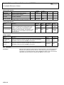
Binary input signals
Signal
Function
Preset reference value
select 0
Preset reference value
select 1
Preset reference value
select 2
Binary-coded switching between the
preset reference values is performed
with the signals preset reference
value select 0 to 3.
Selector
Fieldbus
Image
D124.0
D212 Bit0
D124.1
D212 Bit1
Display
Parameter
Time ON Time OFF
-
-
-
-
D324
D124.2
D212 Bit2
-
-
Preset reference value
select 3
D124.3
D212
1
Bit3
-
-
Preset reference value
accelerating ramp select 0
D126.0
D212 Bit6
-
-
D126.1
D212 Bit7
-
-
D126.2
D212 Bit8
-
-
Preset reference value
accelerating ramp select 3
D126.3
D212 Bit9
-
-
Preset reference value
decelerating ramp select 0
D127.0
D212
Bit10
-
-
D127.1
D212
Bit11
-
-
-
-
-
-
Preset reference value
When D13 is set to 2:binary signals,
accelerating ramp select 1 the signals accelerating ramp select 0
to 3 are used to select the
Preset reference value
accelerating
ramp.
accelerating ramp select 2
Preset reference value
When the parameter D13 is set to
decelerating ramp select 1 2:binary signals, the signals
decelerating ramp select 0 to 3 are
Preset reference value
used
to select the decelerating ramp.
decelerating ramp select 2
Preset reference value
decelerating ramp select 3
KSW-30
D326
D127.2
D212
Bit12
D127.3
D212
Bit13
D327
STÖBER
Comfort Reference Value – 5th Generation of STÖBER Inverters
ANTRIEBSTECHNIK
6. Available Reference Values
Signal
Function
After a switchover of the preset
reference values, preset values, and
accelerating and decelerating ramps,
the change must be accepted with an
enable signal. This prevents
undesired states. The enable is given
when there is a positive edge with the
signal enable preset reference
Enable preset reference
value / preset value (level) value/preset value (edge) or a HIGH
level with the signal enable preset
reference value/preset value (level).
Enable preset reference
value / preset value
(edge)
1
Selector
Fieldbus
Image
Display
Parameter
D128
D212
Bit14
D328
D428.0
D428.1
D129
D212
Bit15
D329
D429.0
D429.1
Time ON Time OFF
D212 bit 3 has a double allocation. When both preset reference values and preset values are addressed via fieldbus, this bit is evaluated as
preset value select 0. This means that eight preset reference values and eight preset values can be selected at the same time. If no preset
values are addressed via fieldbus (i.e., they are addressed via terminals or are not used at all), D212 bit 3 is evaluated as preset reference
value select 3 and 16 preset reference values can be addressed.
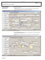
6.2.2 Preset Values
Preset values
The preset values are parameterized on page 3.4.4 of the Assistant (Figure 6-9). The
upper part of this page contains the parameterization of the preset value selection. The
middle section covers the entry of the preset values, and the bottom part concerns the
display parameters for monitoring the current preset value.
Figure 6-9 Parameterizing the preset values
KSW-31
STÖBER
Comfort Reference Value – 5th Generation of STÖBER Inverters
ANTRIEBSTECHNIK
6. Available Reference Values
How to parameterize the
selection of the preset values …
To parameterize the selection of the preset values, proceed as shown below
(Figure 6-10):
• Set the sources of your switchover signals (e.g., BE5 and BE6) in D125.0 and D125.1.
With fieldbus select the setting 2: parameter. In fieldbus mode bits 3 to 5 of the control
word D212 are used as sources.
• Set the enable of the switchover in D128 or D129. The use of an enable prevents
undesired states from occurring. The enable can be given with a positive edge (D128)
or a high level (D129). If the switchover is to take effect immediately, set D129 =
1:high.
• Check the selection in D325 during online operation of POSITool.
Figure 6-10 Parameterizing the preset value selectors
NOTE
Remember that the signals set in D128 and D129 also enable the switchover of the
preset reference values. For more information, see chapter 6.2.2.
How to define preset values …
Preset values are entered in the middle section of page 3.4.4 as described below
(Figure 6-11):
• Use the up/down arrow keys to select the preset value which you want to enter.
• Enter the designation of the preset value (fix value name) (e.g., feed) in the parameter
D26.x.
• Enter the value of the preset value (fix value) (e.g., 100 [rpm]) in D27.x.
• Select the next preset value and keep repeating the procedure until you have defined
all necessary preset values.
Figure 6-11 Entering preset value 0
How to monitor preset values …
Figure 6-12 Monitoring a preset value
KSW-32
After you have transferred your parameterization at the end and an active online
connection has been established between POSITool and the inverter, you can check
your settings in the bottom half of the screen.
STÖBER
Comfort Reference Value – 5th Generation of STÖBER Inverters
ANTRIEBSTECHNIK
6. Available Reference Values
Binary input signals
Signal
Function
Preset value
select 0
Preset value
select 1
The binary-coded switchover between
the preset values takes place with the
preset value select signals 0 to 2.
Preset value
select 2
Selector
Fieldbus
Image
Display
Parameter
D125.0
D212 Bit3
D125.1
D212 Bit4
D125.2
D212 Bit5
Selector
Fieldbus
Image
Display
Parameter
D325
Time ON
Time OFF
-
-
-
-
-
-
Signal
Function
Time ON
Time OFF
Enable preset
reference value /
preset value
(edge)
After a switchover of the preset
reference values, preset values,
acceleration and deceleration ramps, the
change must be accepted by an enable
signal. This prevents undesired states.
D128
The enable is given when the enable
preset reference value/preset value
(edge) signal has a positive edge or the
enable preset reference value/preset
value (level) signal has a HIGH level.
D212 Bit14
D328
D428.0
D428.1
Enable preset
reference value /
preset value
(level)
D129
D212 Bit15
D329
D429.0
D429.1
KSW-33
Comfort Reference Value – 5th Generation of STÖBER Inverters
STÖBER
ANTRIEBSTECHNIK
6. Available Reference Values
6.3
Motor Potentiometer
Information that you will find in
this section …
This section gives you information on:
• when to use the motor potentiometer
• how the motor potentiometer reference value works
• and how to set the reference value
When to use the motor
potentiometer …
Use the motor potentiometer when you want to make a digital change in a reference
value. This means that you raise or lower the reference value via binary signals.
Remember that the motor potentiometer reference value is secure against power
failures. This means that the last valid value is still present after power off and power on
unless a reset has been parameterized for power on (D40 bit 0 – for details see next
section).
All the settings for the motor potentiometer are made on page 3.5 of the Assistant
(Figure 6-13).
Figure 6-13 Making the settings for the motor potentiometer
KSW-34
STÖBER
Comfort Reference Value – 5th Generation of STÖBER Inverters
ANTRIEBSTECHNIK
6. Available Reference Values
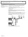
How to parameterize the motor
potentiometer …
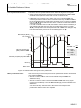
Parameterize the motor potentiometer as shown below. Use Figure 6-14 as a guide:
• Set the sources for the signals motorized pot UP and motorized pot DOWN in D114
and D115. These signals are used to raise or lower the reference value.
• In D43 enter how the change is to be made. If the value 0 is entered in D43, the
motorized pot reference value is raised or lowered with the ramp from D41 or D42 as
long as the applicable binary signal is active (motorized pot UP, motorized pot DOWN,
Figure 6-14 n, p). When both signals are active, no change is made in the reference
value (Figure 6-14 o).
If you enter a value other than 0 in D43, the reference value is raised or lowered by the
value entered in D43 with each rising edge on the digital inputs (Figure 6-14 Step,
q,r,s). This adjustment uses the ramp entered in D41 or D42. A new change in step
is not executed until the previous step is concluded (Figure 6-14 s).
• The ramps of the motorized pot reference value are parameterized in D41 and D42.
Motorized pot (MOP) 1
out constant 0
[rpm]
6
30
2
20
5
3
10
Value of motorized pot
(MOP) reference D380
0
D41, D42 = 10
4
D41 = MOP
ramp 1
D42 = MOP
ramp 2
1
n [rpm]
Motorized pot (MOP) step value D43
Rpm
s
10
0
MOP up
MOP down
1
0
1
0
0
1
2
3
4
5
6
7
8
9
10
t [s]
Figure 6-14 Reference value change with motor potentiometer
Motor potentiometer ramps
There are two ways to use the ramps of the motor potentiometer reference value based
on the parameter D40 bit7.
• When bit 0 is inactive, D41 is used as the acceleration ramp and D42 as the
deceleration ramp.
• When bit 0 is active, a switch is made between D41 and D42 with a binary signal
(signal source set in D117). In this case D41 and D42 apply to both acceleration and
deceleration.
This makes it possible to approach the range of the motor potentiometer reference
value with a fast ramp. After the switch to the second, lower ramp the motor
potentiometer reference value can be adjusted.
KSW-35
STÖBER
Comfort Reference Value – 5th Generation of STÖBER Inverters
ANTRIEBSTECHNIK
6. Available Reference Values
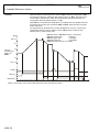
Limitation
When the reference value reaches the values in D45 motorized pot upper limit or D46
motorized pot lower limit, a limitation takes effect (Figure 6-15 n,q). The limits cannot
be exceeded or passed below. When the reference value leaves the limit area, the
change takes effect immediately (Figure 6-15 o).
When D40 bit 5 is activated the signals MOP up and MOP down are disabled when the
torque limits are reached. The parameters E180 and E181 determine when the torque
limits are reached.
The signals MOP up and MOP down are also disabled when a stop or a quick stop is
executed and when the freeze condition is active (A576 control word bit 6) when
DSP402 device control is being used.
D41 MOP ramp 1, D42 (MOP ramp 2) = 500 Rpm/s
D44 MOP preset value
= 250 Rpm
D45 MOP upper limit
= 1500 Rpm
D46 MOP lower limit
= -1000 Rpm
D116 MOP preset source is set to BE1
[rpm]
1
D45=1500
2
1000
Value of
motorized pot
(MOP) out
D380
500
3
6
0
-500
4
D46=-1000
Preset
MOP up
MOP down
1
0
1
0
1
0
0
1
2
3
4
5
6
7
8
9
Figure 6-15 Limitation of the motor potentiometer and reset of the reference value
KSW-36
5
10
11
12
13
14
t [s]
Comfort Reference Value – 5th Generation of STÖBER Inverters
STÖBER
ANTRIEBSTECHNIK
6. Available Reference Values
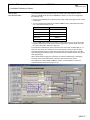
How to reset
the reference value …
You can reset the current reference value to a certain value with signals or events
(Figure 6-15 p,r). Enter the value in D44 MOP PreValue. A reset can be triggered in
the following ways:
• Set a source in D116 which provides a binary signal. A high-level signal causes a reset
to take place.
• You can activate appropriate bits in parameter D40 so that a reset takes place when
one of the following events occurs.
Reset for
By Activation of
Power ON
D40 Bit 0
Stop
D40 Bit 1
Enable OFF
D40 Bit 2
Malfunction
D40 Bit 3
Quick stop
D40 Bit 4
• In bit 6 of D40 select whether the evaluation of the reset events is to be level or edgetriggered. When the bit is inactive the reset is triggered by a positive edge. When the
bit is active the reset is active at a high level.
If several reset conditions are active at the same time the events are OR-linked (i.e., at
least one event must occur before the motor potentiometer reference value is reset).
A reset signal takes priority over the MOP up and MOP down signals (Figure 6-16 s).
With level-triggered evaluation MOP up and MOP down do not take effect as long as the
reset signal is high.
When a limit switch is triggered or a direction of rotation is inhibited (for a description,
see chap. 7) the motor potentiometer reference value is reset to the value 0.
The settings are made in D116 and D40 on page 3.5 of the Assistant. The bits are
activated with the check boxes (Figure 6-16).
Figure 6-16 Setting the reset conditions
KSW-37
STÖBER
Comfort Reference Value – 5th Generation of STÖBER Inverters
ANTRIEBSTECHNIK
6. Available Reference Values
Binary input signals
Signal
Motorized pot up
source
Motorized pot
down source
Function
A high level increases the motor
potentiometer reference value in steps
or continuously, depending on D43.
A high level decreases the motor
potentiometer reference value in steps
or continuously, depending on D43.
Selector
Fieldbus
Image
Display
Parameter
D114
D211 Bit0
D115
Time ON
Time OFF
D314
-
-
D211 Bit1
D315
-
-
Motorized pot
preset source
A high level sets the current motor
potentiometer reference value to the
value entered in D44.
D116
D211 Bit2
D316
D416.0
D416.1
Motorized pot
ramp selection
When D40 bit 7 is active the signal
motorized pot ramp source can be used
to switch between D41 and D42. D41 is D117
used for low level. The ramp D42 is used
for high level.
D211 Bit3
D317
D417.0
D417.1
Status signals
Fieldbus
Image
Signal
Function
Motorized pot out
constant
Signal indication depends on D43.
When the value 0 is entered in D43 the motor potentiometer (MOP) reference
value is changed continuously. Signal 1 is active when the signals MOP up
and MOP down are simultaneously inactive or simultaneously active.
D200 Bit13
When D43 is a value other than 0, reference values are changed in steps. The
signal is 1:active when a step is completed and becomes 0:inactive when a
new step is started.
Motorized pot limit A high level means that the motor potentiometer reference value has reached
the value in D45 or D46.
reached
KSW-38
D200 Bit14
Single
Parameter
D187
D188
STÖBER
Comfort Reference Value – 5th Generation of STÖBER Inverters
ANTRIEBSTECHNIK
6. Available Reference Values
6.4
PID Controller
Information that you will find in
this section …
This section gives you information on:
• when to use the PID controller
• how the PID controller is set up
• and how to set the PID controller
When to use the PID controller …
The PID controller is used to calibrate reference values and actual values via a PID
structure (control). You can use this to implement tension, pressure, or filling level
control, for instance.
Structure of the PID controller
The PID controller must be supplied with a reference value and an actual value (Figure
6-17). A control error is calculated from reference value and actual value which is then
applied to the PID controller (Figure 6-22). You can select and use the result of the PID
structure in D30, D31, or D33.
Source of
technology RV
D52.4
G132
0%
AE1
AE2
AE3
Status of
technology RV
0
SW
RV
D53.4
G332
(-1)
1
D51.4
Preset RV
G100
Motorized pot
0
1
G210 Bit 2
Status of
negation of
technology RV
G300
Source,
technology
actual value
G180
Technology
actual value,
low pass
D52.5
G133
Read parameter
entered in G12
Control error
PID contr.,
control error
BE13
0%
AE1
AE2
AE3
+
-
...
BE1
BE1
Ref. value for
forward feed,
torque control
2
Source of
negation of
technology RV
Control byte,
technology
controller
D34
D54.4
n
Technology
G232
reference value
PID
RV selector
G11
D54.5
n
Technology
actual value
G333
SW
RV
D53.5
D51.5
Figure 6-17 PID controller: Reference value-actual value comparison
KSW-39
Comfort Reference Value – 5th Generation of STÖBER Inverters
STÖBER
ANTRIEBSTECHNIK
6. Available Reference Values
How to parameterize
the reference value
of the controller …
Parameterization is performed on page 3.6.1 of the Comfort Reference Value Assistant.
Proceed as shown below:
• In D34 select whether you want to supply the PID reference value with an analog
signal, preset reference values, or the motor potentiometer.
Figure 6-18 Setting the source for the PID reference value
• If you selected preset reference value or motor potentiometer set the reference values
as shown in chapters 6.2 and 6.3.
• If you set D34 = 0:Reference value extern go to page 3.6.3 of the Assistant (Figure
6-19).
Figure 6-19 Parameterizing the signal source for the external PID reference value
KSW-40
Comfort Reference Value – 5th Generation of STÖBER Inverters
STÖBER
ANTRIEBSTECHNIK
6. Available Reference Values
• Set the source of the analog signal in G132. You can select the analog signals of the
inverter or fieldbus transmission (4:parameter).
• Depending on what you select in G132 additional parameters appear in which you can
parameterize the interface (e.g., an offset for the analog input).
• Scale the characteristic curve of the reference value in the parameters D51.4 to D54.4.
The characteristic curve links the selected input area with the set reference value area
in user units.
Example:
D51.4 = 0.5 V, D52.4 = 8 V
D53.4 = 100 rpm, D54.4 = 1500 rpm
This setting means that 100 rpm is specified when the reference value is 0.5 V and
1500 rpm is specified when the reference value is 8 V. The characteristic curve is
calculated linearly between these two points.
• Go to page 3.6.1 of the Assistant.
• If you want to negate the reference value, specify the source of the signal in G100 with
which you want to execute the negation.
How to parameterize the actual
value of the controller …
The actual value can be parameterized on page 3.6.4 of the Assistant (Figure 6-20).
Proceed as shown below:
• Specify the source of the technology controller in G133. You can select the analog
inputs or fieldbus transmission.
• If you selected an analog input, additional parameters appear in which you can
parameterize the analog interface (e.g., an offset for the analog value).
• If you selected fieldbus transmission enter G233 in the parameter G12. The parameter
G12 gives you the opportunity to use other parameters of the application as actual
values. You can use actual values of data type I16 for this.
• Scale the actual value characteristic curve with the parameters D51.5 to D54.5. The
characteristic curve links the selected input area with the set reference value area in
user units.
Example:
D51.5 = 0.5 V, D52.5 = 8 V
D53.5 = 100 rpm, D54.5 = 1500 rpm
This setting means that 100 rpm is specified when the reference value is 0.5 V and
1500 rpm is specified when the reference value is 8 V. The characteristic curve is
calculated linearly between these two points.
Figure 6-20 Parameterizing the signal source for the actual PID value
KSW-41
Comfort Reference Value – 5th Generation of STÖBER Inverters
STÖBER
ANTRIEBSTECHNIK
6. Available Reference Values
NOTE
The characteristic curve for reference value and actual value makes it possible to adjust
different scaled sources to each other. This makes the PID control error independent of
offset and factor reactions of the signal sources.
• Go to page 3.6.1 of the Assistant.
• Set the actual value low pass in G11 (Figure 6-21).
Figure 6-21 Setting the low pass for the actual PID value
The PID control error is calculated from the reference values and the actual values. This
variable is given to the PID controller. You can monitor the value online in the parameter
G180 on page 3.6.1 of the Assistant.
KSW-42
STÖBER
Comfort Reference Value – 5th Generation of STÖBER Inverters
ANTRIEBSTECHNIK
6. Available Reference Values
How to parameterize the PID
controller …
Figure 6-22 shows the structure of the PID controller. The PID controller is parameterized
on page 3.6.2 of the Assistant. You can access the page by changing to the page in the
Assistant or clicking on the icon for the PID controller on page 3.6.1.
Proceed as described below:
• Set the global gain in the parameter G00 (loop gain).
• The P-portion is determined by the parameter G06. G18 will give you a feedback
message of this controller path during online operation.
• Calculation of the I-portion is parameterized in G02. In certain situations such as PID
initialization or reaching the PID controller limits, the I-portion is set to values other than
those calculated with G02 (for details, see next few sections). The current I-portion can
be read in G19 during online operation.
• Enter the time constant G07 in the D path for smoothing the control error. The
calculation of the D-portion is parameterized in the parameter G03.
• Set the controller limits in G08 and G09. The result of the addition of the P, I and Dportion is limited to these values. Additional information on control operation follows on
the next page.
PID contr.
Kp 2
G06
PID
P-portion
P-portion
G18
Loop gain
PID contr.
Ki
G00
G02
I-portion
P
PID
Calculation
I-portion
G19
Control
error
I
PID mode and
PID limits
PID contr.
low pass
D-portion
G07
D-portion
PID-off
(Source selection G101)
depends on
(G08, G09)
PID contr.
Kd
PID
0
PID control
errror
G03
D
Figure 6-22 PID controller
Additional information on the
PID controller
The PID controller has three states:
1. Deactivated – output permanently set to "zero"
2. Control mode
3. Initialization
How to deactivate the PID
controller …
When the PID controller is deactivated the PID output is set to zero. There are two cases
in which the output is set to zero:
• The enable of the device control A900 is inactive.
• The binary signal whose source you set in G101 on page 3.6.1 of the Assistant (Figure
6-23), is active. The PID value continues to be calculated with this signal is active.
A rising edge of A900 or a falling edge of the selected binary signal enables the output of
the PID controller again. The I-portion is forced to the value of G13. If this initial value
cannot be used for the application various other settings are available for the starting
value. Also read about initializing the PID controller in the next few sections.
KSW-43
Comfort Reference Value – 5th Generation of STÖBER Inverters
STÖBER
ANTRIEBSTECHNIK
6. Available Reference Values
Figure 6-23 Settings for switching the PID controller
Information on control operation
The PID controller output is limited by the parameters G08 (upper limit) and G09 (lower
limit). When the limitation is active the I-portion is set according to the following
conditions:
• If the upper limit is reached (G08) and the sum of the P-portion and the D-portion is
less than G08, then: I=G08-P-D and I ≥ 0.
• If the lower limit (G09) is reached and the sum of the P-portion and D-portion is greater
than G09, then: I=G09-P-D and I ≤ 0.
How to initialize the PID
controller …
Figure 6-24 PID controller
KSW-44
An initialization affects the output of the PID controller and the behavior of the I-portion
as applicable to the application. You can parameterize the initialization on page 3.6.2 of
the Assistant (Figure 6-24).
Comfort Reference Value – 5th Generation of STÖBER Inverters
STÖBER
ANTRIEBSTECHNIK
6. Available Reference Values
You can specify in parameter G102 (set source of PID controller) which signal sets
(presets) the PID controller. You can use the setting of G14 to parameterize how the
initialization is to be performed. The following choices are available (Figure 6-25):
• G14 = 0: Normal
When G14=0, no initialization takes place with "set PID controller" during control
operation.
• G14 = 1: Output = I-Portion = 0
When G14=1, the output and the I-portion are held to 0% when the "set PID controller"
signal is queued.
Practical application:
The "set PID controller" signal is queued before the enable and remains set. The
enable is given and the motor is energized. Regardless of the control difference the
PID output and the I-portion remain at 0%. The motor is only run via "feed forward." If
the system is stable and not vibrating, PID control can be switched on by removing the
"set PID controller" signal.
• G14 = 2: Output = I-Portion = G13
When G14=2, the output and the I-portion are held to the value entered in G13 (PID
initialization value) when the "set PID controller" signal is queued.
Practical application:
During control mode, the "set PID controller" signal can be used to set the output and
the I-portion back to the starting value as with Enable On.
• G14 = 3: Output = G13, = I-Portion = Output - P
When G14=3 and the "set PID controller" signal is queued, the output is held to the
value entered in G13 (PID initialization value) and the I-portion sets itself to the value
PID - P.
Practical application:
During control mode, the "set PID controller" signal can be used to freeze the output to
the value in G13 and the I-portion sets itself according to the P-portion.
• G14 = 4: Output = PID, I-Portion = Hold G13
When G14=4 and the "set PID controller" signal is queued, the output can be
calculated according to the control error G180, the P-gain G06 and a fixed I-portion
(G19=G13). The I-portion is held at the value entered in G13 (PID initialization value).
Practical application:
During control mode, the "set PID controller" signal together with G13=0% can be used
to disable the I-portion and control only with the P-portion. This can be useful for
vibration analysis.
Source PID
controller set
(G102)
0
PID=P+I+D
PID controller
Upper limit
G08
PID mode
PID=0
I=0
PID=G13
I=G13
PID=G13
I=G13 - P
0
1
2
3
G14
PID
1
4
G09
PID controller
Lower limit
PID=P+G13 +D
I=G13
Figure 6-25 Setting the initialization behavior
NOTE
The PID controller can also be switched off with a falling edge of the "disable PID
controller" signal (monitoring parameter G301) and set with the rising edge of the
"enable" signal (parameter A900). However, this setting procedure is different from
initialization via PID controller. The PID controller output and the I-portion are always set
with G13 (PID initialization value) when "enable" and "disable PID controller" occur. "Set
PID controller" causes the PID controller to be initialized based on the setting of the
parameter G14 (PID mode).
KSW-45
STÖBER
Comfort Reference Value – 5th Generation of STÖBER Inverters
ANTRIEBSTECHNIK
6. Available Reference Values
Binary input signals
Signal
Function
Negate PID
reference value
Disable PID
controller
When the signal is active the PID
reference value is negated.
When the signal is active the PID
controller is disabled.
When the signal is active the PID
controller mode is activated as per G14.
Set PID controller
Selector
Fieldbus
Image
Display
Parameter
G100
D211 Bit4
G101
G102
Time ON
Time OFF
G300
-
-
D211 Bit5
G301
-
-
D211 Bit6
G302
-
-
Analog input signals
Signal
Function
Selector
Fieldbus
Image
Display
Parameter
PID reference
value
The functions PID-reference value and PID-actual
value can be addressed as analog signals or via
fieldbus. A control error is calculated from these
signals. The control error is used as the input
variable for the PID controller. The reference value
set in G132 is used when D34 is parameterized to
0:analog signals.
G132
G232
G332
D51.4 to
D54.4
G133
(G12)1
G333
D51.5 to
D54.5
PID actual value
1
Scaling
When G133 is set to 4:parameter the parameter entered in G12 is used as the source. An I16 parameter is entered in G12.
Status signals
Signal
Function
Fieldbus
Image
Single
Parameter
PID upper limit
reached
A high level means that the PID controller has reached the maximum
permissible value (can be set with G08) on the output.
D200 Bit7
G181
PID lower limit
reached
A high level means that the PID controller has reached the minimum
permissible value (can be set with G09) on the output.
D200 Bit8
G182
6.5
N-actual
Description
KSW-46
When the drive follows the master reference value (see chap. 1.2.6), the actual speed is
measured. This measured value is used as n-actual. When synchronous operation is
concluded (i.e., the master reference value is disabled) the slave can be run with its last
valid speed when the reference value path with D30=6:n-actual is used.
STÖBER
Comfort Reference Value – 5th Generation of STÖBER Inverters
ANTRIEBSTECHNIK
7. Additional Functions
7
ADDITIONAL FUNCTIONS
Information that you will find
in this chapter…
This chapter gives you information on:
• what other functions you can use with the Comfort Reference Value application
• and how to parameterize these functions.
Available functions
The following functions are described in this chapter.
• Direction of motor: Change drive motor direction with a binary signal
• High resolution n-reference : Additive value on the current reference value
• Stop: Decelerate the drive down to speed 0
• Jog: Reference value for manual mode, with separate ramps and lock logic.
• Motor rotation lock
• Limit switch: Lock of rotation in excess of a certain point.
The point is indicated with binary signals.
• Local operation: Move the drive with the keyboard of the inverter
• Motor direction: Specification of the direction of the machine
How to parameterize the
functions motor direction,
high-resolution n-reference
and stop ….
The functions motor direction, high-resolution n-reference value and stop are
parameterized on page 4 of the Assistant (Figure 7-1). Proceed as shown below:
• If you want to negate the current reference value (value as per combination or master
reference value), enter a signal source in D100. When the signal has a low level the
reference value is output unchanged. When the signal has a high level the sign of the
reference value is inverted.
• After the negation you can then use the high-resolution n-reference function to have an
additive effect on the value from the D384 indication. The result is indicated in D385.
The high-resolution n-reference function affects both a combined reference value and
a master reference value. It is not dependent on the type of reference value selected
on page 1 of the Assistant.
• If you want to trigger a stop during operation select the source of the stop signal in
D102. When this signal is active the stop is executed. The drive stops with the ramp
set in D84.
NOTE
When a stop is triggered during torque control, then automatically speed operation is
used. The drive will be stopped to a standstill with speed control. If you delete the stop
signal automatically torque control is used again.
KSW-47
Comfort Reference Value – 5th Generation of STÖBER Inverters
STÖBER
ANTRIEBSTECHNIK
7. Additional Functions
Figure 7-1 Settings for direction of revolution and jogging
How to parameterize the jog
function …
As you can see in Figure 7-1 a stop signal must be triggered to activate the jog function.
When the drive has reached the speed window ± C40 the jog reference value can be
enabled by the jog enable.
To parameterize proceed as shown below:
• Set a source for the stop signal in D102 if you haven't yet selected the signal source.
• Select the source of the jog enable in D105. The jog reference value is not used until
the jog enable becomes active. The jog enable can also be implemented via D55 Bit 3
and a simultaneously queued additional enable 2. (See chap. 9.4.)
• Parameterize the sources for the jog+ and jog- signals in D106 and D107. If neither
signal is active the jog reference value is 0. If jog+ is active, the jog reference value is
passed on unchanged. If jog- is active the jog reference value is negated. If both
signals are on, the reference value is set to 0.
• Enter the ramp of the jog reference value in D28.
How to parameterize the jog
reference value …
After making the settings on page 4 of the Assistant, go to page 3.7 (Figure 7-2) to
parameterize the jog reference value. Proceed as shown below:
• Set the signal source of the jog reference value in D135. The reference value is read
from D235 in fieldbus operation (D135 = 4:parameter) or as a constant value.
• If you selected an analog input in D135 additional parameters are indicated. Set the
input with these parameters (e.g., analog input offset).
• Scale the characteristic curve with array parameters D51.3 to D54.3. Scaling specifies
the correct counter-value in user units for each input value.
Example for external reference value:
D51.3 = 0.5 V, D52.3 = 8 V
D53.3 = 100 Rpm, D54.3 = 1500 Rpm
This setting means that 100 Rpm is specified for a reference value of 0.5 V and 1500
Rpm for 8 V. The curve is calculated linearly from these two points.
NOTE
Since triggering the stop function in torque mode causes a switch to speed control
(regardless of the settings on page 1 of the Comfort Reference Value Assistant), jog
mode is only possible with speed control.
KSW-48
Comfort Reference Value – 5th Generation of STÖBER Inverters
STÖBER
ANTRIEBSTECHNIK
7. Additional Functions
Figure 7-2 Parameterizing the signal source of the jog reference value
How to parameterize the
functions direction block, limit
switch and local operation (key
hand function) …
Parameterize the functions direction block, limit switch and local operation on page 6 of
the Assistant (Figure 7-3). Proceed as shown below:
• Set the sources of the signals in D108 and D109 which you want to use to block the
direction of rotation. If one of the signals is active the respective direction is blocked.
You can only proceed in the opposite direction.
• Parameterize the limit switches by first setting the signal sources in D103 and D104. If
one of the signals has a low level the direction exceeding the limit switch is blocked. If
limit switch + triggers you can only proceed in the negative direction. If limit switch has a low level only a positive direction is possible.
Keep in mind the details on the next page on the subject of limit switches.
• Select in D35 whether the drive is to be decelerated with a stop or quick stop ramp
when a limit switch is triggered. When the setting is 0:quickstop ramp, D85 is used.
When the parameterization is 1:stop ramp, D84 takes effect when the value of D84 is
not zero. If this is not the case D85 quick stop ramp is also used for this setting.
• Enter the stop ramp in D84 and the quick stop ramp in D85.
• In C08 set the maximum torque with which the drive is decelerated during a quick stop.
The limits in C03, C05 or other limits specified in the application are ignored during the
quick stop.
• Activate A55 if you want to proceed in local mode. Local mode is activated and
enabled via the display of the inverter.
KSW-49
STÖBER
Comfort Reference Value – 5th Generation of STÖBER Inverters
ANTRIEBSTECHNIK
7. Additional Functions
Figure 7-3 Settings for the limit switch and local operation (key hand) functions
Details on limit switches …
When the drive reaches a limit switch application event 5 is triggered. You can
parameterize the event to inactive level, message, warning or fault. The limit switch is
reset when the drive leaves the limit switch in the opposite direction. This means, for
example, when the positive limit switch triggers and the speed is negative, a falling edge
of the limit switch must be determined.
If a fault was triggered, you can reset the event and then move in the permissible
direction away from the limit switch.
A limit switch mix-up is caught by also polling the speed when the switch is triggered. If
the inverter determines a negative speed when the positive limit switch is triggered, the
inverter is blocked. The device cannot be re-enabled until you turn it off and on again.
Remember that it is essential to reverse the connections of the limit switches or reparameterize and save before you turn on the device again.
CAUTION
• When the speed is polled and a value less than ± C40 is determined, no direction can
be assumed. However, to reset the limit switch anyway, you can delay the limit switch
signal with the switchoff delay until the speed is greater than ± C40.
• The limit switches are evaluated internally as break-contacts. When make-contacts are
connected as limit switches, the binary input in D103 or D104 must be selected
inverted (e.g., 4:BE1-inverted).
Details on local operation (key
hand function)
Press the
button to access local operation.
• You can enable and disable the drive with the
• The motor stops when the
ESC
I/O
button.
button is pressed.
• Use the
buttons to move at the speed specified in D235 as long as the button is
pressed. The value specified in D28 is the acceleration and deceleration ramp.
• A motor potentiometer is simulated with the
is the acceleration and deceleration ramp.
buttons. The value specified in D28
CAUTION
If the device remains in the "switch-on disable" device state because the state is
obtained with a given enable (for bus enable and additional enable) and if a change is
then made to local operation, the inverter is enabled when local operation is exited! This
can cause the drive to move.
KSW-50
STÖBER
Comfort Reference Value – 5th Generation of STÖBER Inverters
ANTRIEBSTECHNIK
7. Additional Functions
How to set the motor direction …
You can use D57 to invert the direction of the motor regardless of the reference value or
the type of reference value. D57 can be used to adjust to a change in mounting position
or a change in the number of stages of a gear unit.
This parameter is available on page 7 of the Assistant.
Binary signals
Signal
Reverse direction
External fault
Stop
Function
When the signal is active the current
direction is reversed.
When the signal is active the device
changes to the "fault" state.
When the signal is active the reference
value 0 is specified. The motor stops.
Selector
Fieldbus
Image
Display
Parameter
D100
D210 Bit0
D300
D400.0
D400.1
D101
D210 Bit1
D301
D401.0
D401.1
D102
D210 Bit2
D302
D402.0
D402.1
D405.0
D405.1
Time ON
Time OFF
Jog enable
When the drive reaches a standstill with
the stop signal active (motor speed is
within ±C40 window), jog mode can be
enabled with the "jog enable."
D105
D210 Bit5
D305
Jog +
When jog mode is enabled and the jog+
signal is active the "jog reference value"
signal is output unchanged.
D106
D210 Bit6
D306
-
-
Jog -
When jog mode is enabled and the jog+
signal is active the "jog reference value"
signal is output negated.
D107
D210 Bit7
D307
-
-
Block positive
direction
When the "block positive direction"
D108
signal assumes the value 1:active no
positive reference values are processed.
D210 Bit8
D308
D408.0
D408.1
Block negative
direction
When the "block negative direction"
signal assumes the value 1:active no
negative reference values are
processed.
D210 Bit9
D309
D409.0
D409.1
D210 Bit3
D303
D403.0
D403.1
D210 Bit4
D304
D404.0
D404.1
Limit switch +
Limit switch -
D109
When the level of the signals "limit
switch + and limit switch - is high
application event 5 is triggered. The type D103
of reaction and the display text can be
specified in parameters U150 to U152.
The device changes to the "fault" state
with the standard setting. The direction
is blocked when the limit switch is
passed. After the fault is acknowledged
D104
movement can continue in the direction
opposite to the switch.
Analog signals
Signal
Function
Selector
Jog reference
value
The "jog reference value" signal can be controlled via
D135
analog input or fieldbus.
Fieldbus
Image
Display
Parameter
D235
D335
Scaling
D51.3 to
D54.3
KSW-51
STÖBER
Comfort Reference Value – 5th Generation of STÖBER Inverters
ANTRIEBSTECHNIK
7. Additional Functions
Status signals
Signal
Function
Fieldbus
Image
Single
Parameter
Direction
Indication of the "direction" signal regardless of the source set in D100.
D201 Bit0
D300
Active direction
The signal shows the direction at the end of the reference value path. A low
level means a positive reference value. A high level means a negative
reference value. The parameter D57 does not affect this signal.
D201 Bit1
D430
Jog active
The signal is 1:active when all the following conditions are fulfilled:
- The jog enable (selector D105) or the jog reference value enable (D55 and
D113 additional enable 2) is active.
D201 Bit8
- A stop command (selector D102) is queued.
- The speed has reached the range -C40 to +C40 once.
D437
Stop active
When the level is high a stop command is queued (D302) and the actual
motor speed has reached the range -C40 to +C40 once.
D201 Bit9
D438
Limit switch
When the level is high one of the limit switches has triggered (D303 or D304).
D202 Bit13
D462
Warning
When the level is high a warning was determined (E81 = 2).
D202 Bit14
D463
Switch-on disable
When the level is high the inverter is in the state "switch-on disable" (E48 = 1). D202 Bit15
D464
KSW-52
Comfort Reference Value – 5th Generation of STÖBER Inverters
STÖBER
ANTRIEBSTECHNIK
8. Parameterizing the Speed and Torque Limits
8
PARAMETERIZING THE SPEED AND TORQUE LIMITS
Information that you will find in
this chapter …
This chapter gives you information on:
• the torque and speed limits which the Comfort Reference Value application offers
• how to change these limits during operation
• and how to set the limits.
8.1
Torque Limits
Information that you will find in
this section …
This section gives you information on:
• what absolute or motoring / generating torque limits are
• which torque limits apply in speed and torque operation
• and how the torque can be limited by additional functions.
You can choose between absolute and motoring / generating limits for variable torque
limitation. Remember that motoring / generating limitation is only available with speed
control.
Absolute torque limits
Absolute torque limits are not dependent on the direction of speed and torque.
Two absolute torque limits can be used in the Comfort Reference Value application. The
limits are designed as analog signals so that the limits can be changed during operation.
The absolute torque limits are available in both speed and torque control.
You can switch between the limits during operation with a binary signal. This can be
used to increase the torque during a heavy duty startup, for example.
How to parameterize absolute
torque limits …
Absolute torque limits are parameterized on page 8.1 of the Assistant (Figure 8-1).
Proceed as shown below:
• Parameterize the source of the switchover signal in D110. When the signal is low the
value from C330 torque limit is used. When the signal is high the value from C331
torque limit 2 is used.
• Go to page 8.1.1 to set the first torque limit.
KSW-53
Comfort Reference Value – 5th Generation of STÖBER Inverters
STÖBER
ANTRIEBSTECHNIK
8. Parameterizing the Speed and Torque Limits
Figure 8-1 Setting the absolute torque limits
• On page 8.1.1 set the source for the first torque limit in C130 (Figure 8-2). You have a
choice of either an analog input or fieldbus operation (setting 4:parameter).
• If you selected an analog input additional parameters appear which you can use to
parameterize the interface.
• Adjust the factor torque limit C06.
• Go to page 8.1.2 to parameterize the second torque limit. Proceed as for the first
torque limit.
Figure 8-2 Setting the signal source for torque limit 1
KSW-54
STÖBER
Comfort Reference Value – 5th Generation of STÖBER Inverters
ANTRIEBSTECHNIK
8. Parameterizing the Speed and Torque Limits
Motor-generated torque limits
Enter a maximum motor torque and a maximum generated torque for the motorgenerated limitation. You can also change these limits with analog signals during
operation. Changing the motor-generated limitation is only useful with speed control. The
limitation does not become active until the display parameters C332 and C333 have a
value other than zero. This deactivates absolute limitation.
How to parameterize the motorgenerated limits ...
The motor-generated torque limits are parameterized on pages 8.2.1 (Figure 8-3 - motor)
and 8.2.2 (Figure 8-3 - generated) of the Assistant. Page 8.2 gives you an overview of
the entire limitation procedure. Proceed as shown below:
• On page 8.2.1 set the source of the motor torque limit in parameter C132. You have a
choice of either an analog input or fieldbus operation (setting 4:parameter).
• If you selected an analog input, additional parameters appear which you can use to
parameterize the interface (e.g., analog input offset).
• If you selected fieldbus operation, the parameter C232 appears which you will write via
fieldbus or with a constant value.
• Go to page 8.2.2 of the Assistant to parameterize the generating torque limit. Proceed
as described for the motor torque limit.
Figure 8-3 Setting the signal source for the motor torque limit
Additional ways to limit
the torque
As you can see on pages 8.1 und 8.2 (Figure 8-4) the current torque can be limited by
further limitations. The effective torque limit is the minimum of:
• either the absolute or the motor-generating torque limit
• the parameters C03 positive torque limit or C05 negative torque limit
2
• and the functions for motor and controller protection (e.g., the i t model).
During online mode you can see the valid torque limit in the parameters E62 (current
positive torque limit) and E66 (current negative torque limit). The parameters E180 and
E181 indicate whether the particular limit is exceeded.
KSW-55
STÖBER
Comfort Reference Value – 5th Generation of STÖBER Inverters
ANTRIEBSTECHNIK
8. Parameterizing the Speed and Torque Limits
Figure 8-4 Setting the motor/generating torque limits
Binary input signals
Signal
Function
Binary signal for switching between the
absolute torque limits (selectors C130
and C131). When the signal is low
Torque switchover
torque limit (C330) is used. When the
signal is high torque limit 2 (C331) is
active.
Selector
Fieldbus
Image
Display
Parameter
D110
D210 Bit10
D310
Time ON
D410.0
Time OFF
D410.1
Analog input signals
Fieldbus
Image
Display
Parameter
Absolute torque limits. The "torque switchover" signal C130
can be used to switch between the limits (e.g., for a
heavy duty startup). These limits remain valid as long
C131
as C332 and C333 are zero.
C230
C330
-
C231
C331
-
C132
C232
C332
-
C133
C233
C333
-
Signal
Function
Torque limit
(absolute)
Torque limit 2
(absolute)
Torque limit
(motor)
Torque limit
(generating)
Torque limits for motor-generating limitation during
speed control. These limits are active when C332
and C333 contain a value other than zero.
Selector
Scaling
Status signals
Signal
Function
Fieldbus
Image
Single
Parameter
Torque limit active When the signal is high the torque has reached the positive or negative torque
D200 Bit2
(static)
limit.
D182
Positive torque
limit status
When the signal is high the torque has reached the positive torque limit.
D200 Bit3
E180
Negative torque
limit status
When the signal is high the torque has reached the negative torque limit.
D200 Bit4
E181
KSW-56
STÖBER
Comfort Reference Value – 5th Generation of STÖBER Inverters
ANTRIEBSTECHNIK
8. Parameterizing the Speed and Torque Limits
Signal
Function
Fieldbus
Image
Single
Parameter
Motor torque limit
status
When the signal is high the torque has reached the motor torque limit.
D200 Bit5
E186
Generating torque
limit status
When the signal is high the torque has reached the generating torque limit.
D200 Bit6
E187
Motor/generating
torque limit
When the signal is high the torque limits are specified as motor and
generating (i.e., the values in C332 and C333 are not zero).
D201 Bit7
D436
8.2
Speed Limits
Information that you will find in
this section …
This section gives you information on:
• which types of speed limits are offered in torque and speed control
• and how to parameterize these speed limits.
Separate speed limits are available for speed and torque control. The positive and
negative limit can be influenced separately for each control mode and, during operation,
via an analog signal.
How to parameterize the speed
limits during torque control …
See page 8.3 of the Assistant for an overview of the speed limits during torque control.
Go to page 8.3.1 to parameterize the positive speed limit. Go to page 8.3.2 to
parameterize the negative speed limit. To parameterize the speed limit proceed as
described below:
• On page 8.3.1 select the source of the positive speed limit in parameter D136 (Figure
8-5). You have a choice of either an analog input or fieldbus operation.
• If you selected an analog input further parameters appear which you can use to
parameterize the interface.
• If you selected fieldbus operation the parameter is indicated which you will write via
fieldbus or with a constant value.
• Go to page 8.3.2 of the Assistant to parameterize the negative speed limit. Proceed as
described for the positive limit.
Figure 8-5 Setting the signal source for the positive speed limit during torque control
KSW-57
Comfort Reference Value – 5th Generation of STÖBER Inverters
STÖBER
ANTRIEBSTECHNIK
8. Parameterizing the Speed and Torque Limits
NOTE
The speed limits can only be set in Rpm (speed of the motor) during torque control. The
display in user units is reserved for scaling the torque or the force.
How to parameterize speed limits
during speed control …
Page 9.3 of the Assistant gives you an overview of the speed limits during speed control.
The positive speed limit is parameterized on page 9.3.1. The negative speed limit is
parameterized on page 9.3.2. To parameterize the speed limit proceed as described
below:
• On page 9.3.1 select the source of the positive speed limit in parameter D138 (Figure
8-6). You have a choice of either an analog input or fieldbus operation.
• If you selected an analog input further parameters appear which you can use to
parameterize the interface.
• If you selected fieldbus operation the parameter is indicated which you will write via
fieldbus.
• Go to page 9.3.2 of the Assistant to parameterize the negative speed limit. Proceed as
described for the positive limit.
Figure 8-6 Setting the signal source of the positive speed limit during speed control
NOTE
Limits set in these parameters do not deactivate the speed limit C01. C01 may have to
be adjusted to prevent premature limitation by this parameter.
KSW-58
STÖBER
Comfort Reference Value – 5th Generation of STÖBER Inverters
ANTRIEBSTECHNIK
8. Parameterizing the Speed and Torque Limits
Analog signals
Signal
Function
Selector
Fieldbus
Image
Display
Parameter
Max pos. speed,
torque control
Positive speed limit with torque control
D136
D236
D336
-
Max. neg. speed,
torque control
Negative speed limit with torque control
D137
D237
D337
-
Max. pos. speed,
speed control
Positive speed limit with speed control
D138
D238
D338
-
Max. neg. speed,
speed control
Negative speed limit with speed control
D139
D239
D339
-
Signal
Function
Fieldbus
Image
Single
Parameter
Standstill
When the signal is high the actual motor speed has reached the value 0 Rpm,
± C40.
D200 Bit0
D180
When the signal is high the ramp generator has reached the reference value.
D200 Bit1
D181
D200 Bit9
D183
D200 Bit10
D184
Max. speed limit
reached
When the signal is high the reference value has reached the speed limit which
D200 Bit11
is specified by the source set in D138.
D185
Min. speed limit
reached
When the signal is high the reference value has reached the speed limit which
D200 Bit12
is specified by the source set in D139.
D186
Zero ramp
reached
When the signal is high the ramp generator has reached the value 0.
D200 Bit15
D189
Signal
Function
Fieldbus
Image
Single
Parameter
Scan active
When the signal is high the drive is in "scan active" mode as per C20.
D201 Bit4
D433
Heavy duty start
When the signal is high the drive is in "heavy duty start" mode as per C20.
D201 Bit5
D434
Reference value
ready
The signal is active when the inverter is enabled and the brake is open.
D201 Bit6
D435
Positive torque
active
When the signal is high the current torque (E90) as related to the user
direction (D57) is greater than 5%.
D201 Bit11
D440
Negative torque
active
When the signal is high the current torque (E90) as related to the user
direction (D57) is less than -5%.
D201 Bit12
D441
Forward direction
When the signal is high the speed (E91) as related to the inverted user
direction (D57) is greater than C40.
D201 Bit13
D442
Accelerating
When the signal is high the motor speed increases.
D201 Bit14
D443
Decelerating
When the signal is high the motor speed decreases.
D201 Bit15
D444
Reference value
reached
Actual value
reached
Reference value
prohibited
When the signal is high the motor speed (E91) has reached the reference
specification (E07), ± C40.
When the signal is high a positive or negative reference value is specified
although the applicable direction is disabled (D308 = 1:active or D309 =
1:active).
Scaling
KSW-59
Comfort Reference Value – 5th Generation of STÖBER Inverters
STÖBER
ANTRIEBSTECHNIK
9. Additional Functions
9
ADDITIONAL FUNCTIONS
Information that you will find in
this chapter …
This chapter gives you information on:
• skipping speed
• brake activation
• range control and display scaling and
• events.
9.1
Skipping Speed
How to parameterize skipping
speeds …
System vibration can be prevented by skipping over speeds in certain sympathetic
vibration areas. A total of 4 skipped speed areas can be defined. Go to page 9.1 of the
Assistant (Figure 9-1) to parameterize the skipping speeds. Proceed as described below:
• Enter a speed in C11.x. The value should be in the middle of the area to be skipped.
• Enter a speed range in C10.x. The area to be skipped is calculated as follows from
this:
Range = (C11.x – C10.x) to (C11.x + C10.x)
Parameters with the same parameter element create one skip (e.g., C10.4 with C11.4).
Figure 9-1 Setting the speed skip
KSW-60
STÖBER
Comfort Reference Value – 5th Generation of STÖBER Inverters
ANTRIEBSTECHNIK
9. Additional Functions
A plant has sympathetic vibration in the speed range from 520 Rpm to 580 Rpm. This
results in the parameter C11.0 = 550 Rpm and a range of C10.0 = 30 Rpm.
Example
Figure 9-2 shows the interrelationship between the reference value progressions for a
skipped position. When the reference value reaches the lower speed range (in our
example: < 520 Rpm) the lower limit is output until the reference value reaches the upper
limit. The drive is then accelerated with the quick stop ramp until it reaches the upper
limit (580 Rpm).
With a decreasing reference value the jump occurs in the opposite direction (i.e., the
drive is held at the upper limit until the reference value reaches the lower limit).
D387 ref.
value after
skipping
600
[Rpm]
550
500
0
0
500
550
600
Figure 9-2 Progression of speed skipping
D386 reference value
after blocking & local
mode [Rpm]
Status signals
Signal
Function
Fieldbus
Image
Single
Parameter
In area to be
skipped
When the signal is high the motor speed is in the area to be skipped (C10.X,
C11.X).
D201 Bit10
D439
KSW-61
Comfort Reference Value – 5th Generation of STÖBER Inverters
STÖBER
ANTRIEBSTECHNIK
9. Additional Functions
9.2
Brake Activation
How to parameterize
brake activation….
The brake is always switched on and off with the system enable A900. In this case brake
release and brake set times are ignored.
To specify the physical factors of motor and brake, parameterize activation of the brake
on page 9.2 of the Assistant (Figure 9-3).
Remember that the screen on page 9.2 depends on the particular control mode which is
set (B20 control mode). The screen shown in Figure 9-3 is the one which appears when
a control mode without feedback is parameterized in B20 (B20 = 0:V/f control or 1:
sensorless vector control). If you set a control mode with feedback in B20
(B20 = 3:vector control or 64:servo control), the parameters F01 and F02 do not appear
on page 9.2 and the characteristic curves are different.
The brake activation as you parameterized it on page 9.2 is triggered with the system
enable A900, a stop (signal source set in D102 stop source) or a quick stop (signal
source set in A62 quick stop source).
To parameterize proceed as described below:
• Activate brake activation in parameter F08. In the setting 1:active the current motor
torque is stored when the brake closes. This torque is re-established when the brake
opens again. When F08 is set to 2:do not save torque only the motor magnetization
(flux) is established when the brake opens.
• Enter the speed in F02 at which the brake is to be applied.
• Enter the speed in F01 at which the brake is to be released.
• Enter the time in B27 during which the motor is to remain magnetized (in flux) after the
brake procedure is triggered.
• Enter the percentage of the halt flux in B25 which is to be maintained after the time in
B27.
• Enter the time in F07 which the brake requires to be applied.
• Enter the time in F06 which the brake requires to be released.
If you use the motors with brakes from STÖBER ANTRIEBSTECHNIK GmbH & Co. KG,
you will find the correct values for F07 and F06 in the catalogs.
If you use a servo motor with EnDat® encoder, F07 and F06 are automatically read from
the electronic nameplate.
Figure 9-3 Parameterizing brake activation
KSW-62
STÖBER
Comfort Reference Value – 5th Generation of STÖBER Inverters
ANTRIEBSTECHNIK
9. Additional Functions
Status signals
Signal
Function
Fieldbus
Image
Single
Parameter
Brake open
When the signal is high the brake is open. The signal becomes inactive when
the brake begins to close.
D201 Bit2
D431
Brake closed
The signal is 1:active when the brake is closed. The parameter becomes
0:inactive when the brake begins to open.
D201 Bit3
D432
9.3
Range Control and Display Scaling
Description
The "range control" function gives you an opportunity to monitor a value in data format
I16. When the parameter exceeds a user specified limit you you can have an event
triggered (message, warning or fault).
There are two range controls available. Go to pages 10.1 und 10.2 of the Assistant to set
the control. The following description is based on "range control 1" on page 10.1 of the
Assistant (Figure 9-4).
• Enter the parameter in D60 which you want to monitor. Remember that this parameter
must be in data format I16. If you want to monitor an I32-format parameter you can
scale it to the I16 format with "display scaling." For more information read the following
sections.
• Enter a factor in D61 with which the parameter is to be weighted.
Remember that an entry of 25% corresponds to the factor 1 since a further
multiplication with the factor 4 takes place internally.
• Enter the time constant of the low pass in D62. The low pass smoothes the
progression of the value to be monitored. The result after smoothing is indicated in
D69.
• Specify in D63 how the value indicated in D69 is to be monitored. When D63 is set to
0:range the limits D64 to D67 are evaluated unchanged. When D64 = -50% and D67 =
60% are parameterized the valid working range is between -50% and 60% in this case.
With 1:absolute the limits specified in D64 to D67 are evaluated symmetrically to zero.
When D64 = 50% and D67 = 60% are parameterized the valid working range is
between +50% and +60% or -60% and -50%.
• Enter the limits of the control in D64 to D67.
D64 determines the lowest limit of range control. When the value in D69 passes below
this limit D190 is active and event 60 is triggered.
D65 determines the first lower limit of range control. When this limit is passed below
D191 indicates and signals that the value in D69 is approaching the critical limit D64.
When the value in D69 is between D65 and D66 this is indicated by D192.
D66 determines the first upper limit of range control. When this limit is exceeded D193
indicates and signals that the value in D69 is approaching the critical limit D67.
D67 determines the highest upper limit of range control. When the value in D69
exceeds this limit D194 is active and event 61 is triggered.
• Specify in D68 whether control range is limited to static operation. When 0:inactive is
parameterized range control is not performed during accelerations or disabled drive.
Event signals D190 to D194 are set to 0:inactive. When D68 is parameterized to
1:active range control is performed continuously and D190 to D194 are set
accordingly.
Range control 2 on page 10.2 of the Assistant is parameterized as described here.
KSW-63
Comfort Reference Value – 5th Generation of STÖBER Inverters
STÖBER
ANTRIEBSTECHNIK
9. Additional Functions
Figure 9-4 Setting range control
KSW-64
Comfort Reference Value – 5th Generation of STÖBER Inverters
STÖBER
ANTRIEBSTECHNIK
9. Additional Functions
How to parameterize
the events …
Go to page 10.3 of the Assistant (Figure 9-55) to parameterize the events. The level of
the events is set in U100 or U110 for range control 1 and in U120 or U130 for range
control 2. You can select from the following settings.
• When 0:inactive is set an exceeded limit has no reaction.
• With all other settings a parameter is indicated in which you can enter a designation.
This designation is shown on the inverter's display when the event is triggered.
• When 1:message is parameterized the choosen designation is shown on the display.
Operation is continued.
• When 2:warning is set a parameter is indicated in which you enter a time. When the
event occurs operation is continued for this time. The event is indicated on the display.
After this time expires the warning is converted into a fault. The inverter switches to the
device state "fault."
• When you parameterize 3:fault the inverter changes immediately to the device state
"fault" when a limit is violated.
Figure 9-5 Parameterizing the events for range control
KSW-65
STÖBER
Comfort Reference Value – 5th Generation of STÖBER Inverters
ANTRIEBSTECHNIK
9. Additional Functions
How to scale I32 values to I16
format …
Parameters D98.X and D99.X can be used to scale I32 parameters, which are shown in
user units, to I16 values in relation to D56. Go to page 11 of the Assistant and proceed
as described below (Figure 9-6):
• Enter the I32 parameter in D98.X.
• The value scaled in I16 can be read out in the same element in array D99.X. This
value can then be entered in the "range control" function.
Scaling can also be used to indicate I32 values on analog outputs.
Figure 9-6 Parameterizing the scaling
Status signals
Signal
Function
Fieldbus
Image
Single
Parameter
Range control 1,
red, below
The signal is 1:active when the value indicated in D69 is below the limit
entered in D64 (D69 < D64).
D202 Bit0
D190
Range control 1,
yellow, below
The signal is 1:active when the value indicated in D69 is between the values
D64 and D65 (D64 < D69 < D65).
D202 Bit1
D191
Range control 1,
green
The signal is 1:active when the value indicated in D69 is between the values
D65 and D66 (D65 < D69 < D66).
D202 Bit2
D192
Range control 1,
yellow, above
The signal is 1:active when the value indicated in D69 is between the values
D66 and D67 (D66 < D69 < D67).
D202 Bit3
D193
Range control 1,
red, above
The signal is 1:active when the value indicated in D69 is above the limit
entered in D67 (D69 > D67).
D202 Bit4
D194
Range control 2,
red, below
The signal is 1:active when the value indicated in D79 is below the limit
entered in D74 (D79 < D74).
D202 Bit5
D195
Range control 2,
yellow, below
The signal is 1:active when the value indicated in D79 is between the values
D74 and D75 (D74 < D79 < D75).
D202 Bit6
D196
Range control 2,
green
The signal is 1:active when the value indicated in D79 is between the values
D75 and D76 (D75 < D79 < D76).
D202 Bit7
D197
Range control 2,
yellow, above
The signal is 1:active when the value indicated in D79 is between the values
D76 and D77 (D76 < D79 < D77).
D202 Bit8
D198
Range control 2,
red, above
The signal is 1:active when the value indicated in D79 is above the limit
entered in D77 (D79 > D77).
D202 Bit9
D199
KSW-66
Comfort Reference Value – 5th Generation of STÖBER Inverters
STÖBER
ANTRIEBSTECHNIK
9. Additional Functions
9.4
Reference Value Enable
Description
The reference values "external reference value," "correct ref1 and 2," "jog ref value,"
"PID ref value" and "PID actual value" generate a reference value enable. Go to page 12
of the Assistant to activate the evaluation of the reference value enable in D55 (Figure
9-7).
Figure 9-7 Parameterizing the reference value enable
The reference value enables to be used are activated by individual bit:
Bit in D55
Enable of the Reference
Value
Bit 0
Reference value external
Bit 1
Correct ref1
Bit 2
Correct ref2
Bit 3
Jog ref value
Bit 4
PID ref value
Bit 5
PID actual value
The enable of a reference value is active when the applicable bit is active in D55 and the
reference value has reached the value in the related parameter 51.X. The reference
value enable is AND-linked with the signal AdditionalEnable 2 (selector D113, indication
D313). When both signals are active the device enable can be given together with the
hardware enable on X1.
You can use several reference value enables at the same time. If you do, at least one of
the reference value enables must be active.
KSW-67
STÖBER
Comfort Reference Value – 5th Generation of STÖBER Inverters
ANTRIEBSTECHNIK
9. Additional Functions
9.5
Events
Description
The Comfort Reference Value application allows you to:
• trigger an inverter malfunction with an external signal and
• indicate the occurrence of an event.
External triggering of a
malfunction
Go to page 12 of the Assistant (Figure 9-7) to parameterize the triggering of an event.
Set the signal source in D101. You can choose between fieldbus and binary input.
External malfunction:
Fault
44:Text from U180
Trigger:
Application event
Level:
Malfunction
Acknowledgment: Switch device off/on or programmed acknowledgment
Other:
Should only be used for application events which may not
be set lower than "malfunction" level.
Event counter:
Z44
Indicate a certain event
You can indicate the occurrence of two different events (from E82 event type). Enter the
event to be monitored in D90 or D91. The parameters are located on page 12 of the
Assistant (Figure 9-7). You will find the number of the event in the event table in chapter
4 of the application manual. When the event is determined in E82 parameter D460 or
D461 is set to 1:active.
Example:
When the permissible maximum torque for operation is exceeded, an indication is to be
made in BA1.
Solution:
Enter the value 47 in D90. Event 47 shows that the permissible maximum torque has
been exceeded.
Enter the coordinates D460 in F61.
This causes the occurrence of fault 47 to be indicated at BA1.
Signal
Function
Fieldbus
Image
Single
Parameter
External
malfunction
A high level means that an external signal for triggering a malfunction is
queued.
D202 Bit10
D301
Event value A
When the level is high the event entered in D90 has occurred.
D202 Bit11
D460
Event value B
When the level is high the event entered in D91 has occurred.
D202 Bit12
D461
KSW-68
Comfort Reference Value – 5th Generation of STÖBER Inverters
STÖBER
ANTRIEBSTECHNIK
10. Fieldbus
10
FIELDBUS
Information that you will in this
chapter …
This chapter shows you how to implement a fieldbus coupling for the "Comfort Reference
Value" application. When you connect a fieldbus, be sure to:
• select the appropriate device controller in the configuration assistant,
• install the appropriate option board if you are using CAN, PROFIBUS DP or EtherCAT
and
• configure the option in the configuration assistant.
You will be provided with an assistant in the global sector for the configured fieldbus.
You can access the fieldbus parameters such as bus address or mapping parameters
with this assistant.
The control and status words
You can write binary signals to the inverter in the "Comfort Reference Value" application
via the control words:
• A180 device control byte,
• D210 speed reference value control word,
• D211 speed reference value control word 2 or
• D212 speed reference value control word 3.
You can specify in the selector of a signal whether the signal is to be written via a binary
input or fieldbus. If you use transmission via fieldbus, set 2:parameter in the selector.
The description of the selector tells you which control word and which bit has to be
written.
The following parameters are available as status words.
• E200 device status byte,
• D200 speed reference value status word,
• D201 speed reference value status word 2 and
• D202 speed reference value status word 3.
You do not have to allocate the status words to bits like you do for the control words. The
signals are automatically written to the bits.
In online mode you can monitor the control and status words on pages 17 to 20 of the
"Comfort Reference Value" assistant.
When you connect
a CAN bus
The CAN fieldbus interface provides you with the following:
• Two PDO channels (tx / rx).
• One SDO channel (tx / rx).
• If necessary, three additional SDO channels (tx / rx).
Cf. CANopen documentation, impr.-no. 441684.
When you connect
a PROFIUS DP
The PROFIBUS DP fieldbus interface provides you with the following:
• GSD file
• PPO 1: 4 PKW, 2 PZD
• PPO 2: 4 PKW, 6 PZD
• PPO 3: 0 PKW, 2 PZD
• PPO 4: 0 PKW, 6 PZD
• PPO 5: 4 PKW, 10 PZD
• Support of the DP-V1 protocol
Cf. PROFIBUS DP documentation, impr.-no. 441685.
When you connect
an EtherCAT fieldbus
The EtherCAT fieldbus interface provides you with the following:
• Two PDO channels (tx / rx).
• One SDO channel (tx / rx).
Cf. EtherCAT documentation, publ.-no. 441896.
KSW-69
STÖBER
Comfort Reference Value – 5th Generation of STÖBER Inverters
ANTRIEBSTECHNIK
11. Used Parameters
11
USED PARAMETERS
11.1
Parameter legend
Par.
Description
C230
Torque limit: Specification for the torque limit (absolute value) via fieldbus if the signal source is
C130=4:Parameter.
Global
Fieldbus
address
0h
Value range in %: -200 to 200 to 200
r=2, w=2
Fieldbus: 1LSB=1·%; PDO ; type: I16; (raw value:32767 = 200 %); USS address: 03 39 80 00 hex
Global – Parameter is not dependent on
axis.
Achse – Parameter is axis-specific.
Off
– Parameter can only be changed
when enable is off.
Access level for read (r=2) and
write accesses (w=2)
11.2
24E6h
Value range:
Specification of unit, minimum
and maximum value
The default setting is
underlined.
PROFIBUS = PNU (PKW1)
CAN-Bus = Index
PROFIBUS = Subindex
CAN-Bus = Subindex
Fieldbus:
1st position: Scaling for integer (PROFIBUS and CAN bus)
2nd position: - PDO – Parameters can be imaged as process data.
- Blank – Parameter can only be accessed via PKW (PROFIBUS) or SDO
(CAN bus).
3rd position: Data type. See application manual, chapter 3.2.
4th position: Scaling for raw values
5th position: USS address
Parameter list
A.. Inverter
Par.
Description
A00.0
Global
r=0, w=0
Save values & start: When this parameter is activated, the inverter saves the current
configuration and the parameter values in the Paramodule. After power-off, the inverter starts with
the saved configuration. If the configuration data on the inverter and Paramodul are identical, only
the parameters are saved (speeds up the procedure).
Fieldbusaddress
2000h
0h
2000h
1h
2000h
2h
NOTE
Do not turn off the power of the control section (device version /L:24 V, device version /H: supply
voltage) while the action is being executed. If the power is turned off while the action is running this
causes incomplete storage. After the device starts up again the fault "*ConfigStartERROR
parameters lost" appears on the display. Only several 1000 storage procedures are possible per
Paramodul. When this limit has almost been reached, result 14 is indicated after the storage
procedure. When this happens, replace Paramodul as soon as possible.
Fieldbus: 1LSB=1; Type: U8; USS-Adr: 01 00 00 00 hex
A00.1
Process: Shows the progress of the "save vales" action in %.
Global
Fieldbus: 1LSB=1%; Type: U8; USS-Adr: 01 00 00 01 hex
read (0)
A00.2
Result: Result of the "save values" action
Global
0: error free;
10: write error;
11: invalid data;
12: write error;
14: warning;
read (0)
Fieldbus: 1LSB=1; Type: U8; USS-Adr: 01 00 00 02 hex
KSW-70
STÖBER
Comfort Reference Value – 5th Generation of STÖBER Inverters
ANTRIEBSTECHNIK
11. Used Parameters
A.. Inverter
Par.
Description
A10.0
Global
r=0, w=0
Userlevel: Specifies the access level of the user for the parameters via the "Display"
communication path. Each parameter has one level for read or write accesses. A parameter can
only be read or changed with the necessary access level.
The higher the set level the more parameters can be accessed.
Fieldbusaddress
200Ah
0h
Array
Possible settings:
0: Monitor; The elementary indicators can be monitored. General parameters can be changed.
1: Standard; The primary parameters of the selected application can be monitored and changed.
2: Extended; All parameters for commissioning and optimization of the selected application can be
monitored and changed.
3: Service; Service parameters. Permit a comprehensive diagnosis.
Value range: -32768 ... 1 ... 32767
Fieldbus: 1LSB=1; Type: I16; USS-Adr: 01 02 80 00 hex
A10.1
Global
r=0, w=0
Userlevel: Specifies the access level of the user for the parameters via the RS232 (X3)
communication path. Each parameter has one level each for read or write accesses. A parameter
can only be read or changed with the necessary access level.
The higher the set level the more parameters can be accessed.
200Ah
1h
Array
Possible settings:
0: Monitor; The elementary indicators can be monitored. General parameters can be changed.
1: Standard; The primary parameters of the selected application can be monitored and changed.
2: Extended; All parameters for commissioning and optimization of the selected application can be
monitored and changed.
3: Service; Service parameters. Permit a comprehensive diagnosis.
Value range: -32768 ... 3 ... 32767
Fieldbus: 1LSB=1; Type: I16; USS-Adr: 01 02 80 01 hex
A10.2
Global
r=0, w=0
Userlevel: Specifies the access level of the user for the parameters via the CAN-bus (SDO)
communication path. Each parameter has one level each for read or write accesses. A parameter
can only be read or changed with the necessary access level.
The higher the set level the more parameters can be accessed.
200Ah
2h
Array
Possible settings:
0: Monitor; The elementary indicators can be monitored. General parameters can be changed.
1: Standard; The primary parameters of the selected application can be monitored and changed.
2: Extended; All parameters for commissioning and optimization of the selected application can be
monitored and changed.
3: Service; Service parameters. Permit a comprehensive diagnosis.
Value range: -32768 ... 3 ... 32767
Fieldbus: 1LSB=1; Type: I16; USS-Adr: 01 02 80 02 hex
A10.3
Global
r=0, w=0
Userlevel: Specifies the access level of the user for the parameters via the PROFIBUS
communication path with the PKW0 or PKW1 protocol. Each parameter has one level each for read
or write accesses. A parameter can only be read or changed with the necessary access level.
The higher the set level the more parameters can be accessed.
200Ah
3h
Array
Possible settings:
0: Monitor; The elementary indicators can be monitored. General parameters can be changed.
1: Standard; The primary parameters of the selected application can be monitored and changed.
2: Extended; All parameters for commissioning and optimization of the selected application can be
monitored and changed.
3: Service; Service parameters. Permit a comprehensive diagnosis.
Value range: -32768 ... 3 ... 32767
Fieldbus: 1LSB=1; Type: I16; USS-Adr: 01 02 80 03 hex
KSW-71
Comfort Reference Value – 5th Generation of STÖBER Inverters
STÖBER
ANTRIEBSTECHNIK
11. Used Parameters
A.. Inverter
Par.
Description
A10.4
Global
r=0, w=0
Userlevel: Specifies the access level of the user for the parameters via the "system bus"
communication path. Each parameter has one level each for read or write accesses. A parameter
can only be read or changed with the necessary access level.
The higher the set level the more parameters can be accessed.
Fieldbusaddress
200Ah
4h
Array
Possible settings:
0: Monitor; The elementary indicators can be monitored. General parameters can be changed.
1: Standard; The primary parameters of the selected application can be monitored and changed.
2: Extended; All parameters for commissioning and optimization of the selected application can be
monitored and changed.
3: Service; Service parameters. Permit a comprehensive diagnosis.
Value range: -32768 ... 3 ... 32767
Fieldbus: 1LSB=1; Type: I16; USS-Adr: 01 02 80 04 hex
A11.0
Global
r=1, w=1
Edited Axe: Specifies the axis to be edited via device display. Axis to be edited (A11) and active
axis (operating indicator, E84) must not be identical (e.g., axis 1 can be edited while the inverter
continues with axis 2).
200Bh
0h
Array
Value range: 0 ... 0: axis 1 ... 3
Fieldbus: 1LSB=1; Type: U8; USS-Adr: 01 02 C0 00 hex
A11.1
Global
r=1, w=1
Edited Axe: Selects the axis to be parameterized which is addressed with CANopen with SDO
channel 1 or with PROFIBUS DP-V0. The axis to be edited (A11) and the active axis (operation
indicator, E84) must not be identical (e.g., axis 1 can be edited while the inverter continues with
axis 2). With PROFIBUS DP-V0, a distinction can be made between two axes with the PKW
service. Axis 1 or axis 2 is selected with A11.1=0. Axis 3 or axis 4 is selected with A11.1=1.
200Bh
1h
Array
Value range: 0 ... 0: axis 1 ... 3
Fieldbus: 1LSB=1; Type: U8; USS-Adr: 01 02 C0 01 hex
A11.2
Global
r=1, w=1
Edited Axe: Selects the axis to be parameterized which is addressed with CANopen with SDO
channel 2. The axis to be edited (A11) and the active axis (operation indicator, E84) must not be
identical (e.g., axis 1 can be edited while the inverter continues with axis 2).
200Bh
2h
Array
Value range: 0 ... 0: axis 1 ... 3
Fieldbus: 1LSB=1; Type: U8; USS-Adr: 01 02 C0 02 hex
A11.3
Global
r=1, w=1
Edited Axe: Selects the axis to be parameterized which is addressed with CANopen with SDO
channel 3. The axis to be edited (A11) and the active axis (operation indicator, E84) must not be
identical (e.g., axis 1 can be edited while the inverter continues with axis 2).
200Bh
3h
Array
Value range: 0 ... 0: axis 1 ... 3
Fieldbus: 1LSB=1; Type: U8; USS-Adr: 01 02 C0 03 hex
A11.4
Global
r=1, w=1
Edited Axe: Selects the axis to be parameterized which is addressed with CANopen with SDO
channel 4. The axis to be edited (A11) and the active axis (operation indicator, E84) must not be
identical (e.g., axis 1 can be edited while the inverter continues with axis 2).
200Bh
4h
Array
Value range: 0 ... 0: axis 1 ... 3
Fieldbus: 1LSB=1; Type: U8; USS-Adr: 01 02 C0 04 hex
A12
Language: Language on the display.
Global
0: German/primary language;
1: English/secondary language;
r=1, w=1
A21
KSW-72
0h
2015h
0h
Fieldbus: 1LSB=1; Type: U8; USS-Adr: 01 03 00 00 hex
Brake resistor R: Resistance value of the brake resistor being used.
Global, OFF Value range in Ohm: 200.0 ... 300,0 ... 600.0
r=1, w=2
200Ch
Fieldbus: 1LSB=0,1Ohm; Type: I16; USS-Adr: 01 05 40 00 hex
Comfort Reference Value – 5th Generation of STÖBER Inverters
STÖBER
ANTRIEBSTECHNIK
11. Used Parameters
A.. Inverter
Par.
Description
A22
Global, OFF
r=1, w=2
A23
Brake resistor P: Power of the brake resistor used. A22=0 means the brake chopper is
deactivated. Only values in 10 W increments can be entered.
Fieldbusaddress
2016h
0h
2017h
0h
201Dh
0h
2022h
0h
2023h
0h
2024h
0h
2025h
0h
2025h
1h
Value range in W: 0 ... 150 ... 3200
Fieldbus: 1LSB=1W; Type: I16; (raw value:1LSB=10·W); USS-Adr: 01 05 80 00 hex
Brake resistor thermal: Thermal time constant of the brake resistor.
Global, OFF Value range in s: 1 ... 46 ... 2000
r=1, w=2
Fieldbus: 1LSB=1s; Type: I16; USS-Adr: 01 05 C0 00 hex
A29
Fault quick-stop: If the parameter is inactive, the power section is turned off when a fault
occurs. The motor coasts down. If the parameter is active, a quick stop is executed when a fault
occurs if the event permits (see event list).
Global
r=2, w=2
0: inactive; Coast down (disable power section immediately).
1: active; Execute quick stop.
Fieldbus: 1LSB=1; Type: U8; USS-Adr: 01 07 40 00 hex
A34
Global
r=2, w=2
Auto-start: When A34=1 is set, the device state "switch-on disable" to "ready for switch-on" is
exited both during first startup and after a fault reset although the enable is active. With fault reset
via enable, this causes an immediately restart! A34 is only supported with standard device state
machines and not with DSP402 device state machine.
WARNING
Before activation of auto-start with A34=1, check to determine whether an automatic restart is
allowed (for safety reasons). Only use auto-start under consideration of the standards and
regulations which are applicable to the plant or machine.
0: inactive; After power on, a change of the enable from L-level to H-level is necessary to enable
the drive (→ message "1:switch-on disable"). This prevents an undesired startup of the motor
(machine safety).
1: active; If auto-start is active, the drive can start running immediately after power on and existing
enable.
Fieldbus: 1LSB=1; Type: U8; USS-Adr: 01 08 80 00 hex
A35
Low voltage limit: When the inverter is enabled and the DC link voltage goes lower than the
value set here, the inverter triggers the indication of the event "46:Low voltage." A35 should be
Global, OFF
approximately 85% of the applied power voltage so that the possible failure of a network phase is
absorbed.
r=2, w=2
Value range in V: 180.0 ... 350,0 ... 570.0
Fieldbus: 1LSB=0,1V; Type: I16; USS-Adr: 01 08 C0 00 hex
A36
Global, OFF
r=2, w=2
A37.0
Global
r=2, w=2
Mains voltage: Maximum voltage which the inverter provides to the motor. Usually the power
(mains) voltage. Starting with this voltage, the motor runs in the weak field range.
Value range in V: 220 ... 400 ... 480
Fieldbus: 1LSB=1V; Type: I16; (raw value:32767 = 2317 V); USS-Adr: 01 09 00 00 hex
Reset memorized values & start: The six different memorized values E33 to E38 (max.
current, max. temperature, and so on) are reset.
Fieldbus: 1LSB=1; Type: U8; USS-Adr: 01 09 40 00 hex
A37.1
Process: Progress of the reset-memorized-values action in %.
Global
Fieldbus: 1LSB=1; Type: U8; USS-Adr: 01 09 40 01 hex
read (2)
KSW-73
Comfort Reference Value – 5th Generation of STÖBER Inverters
STÖBER
ANTRIEBSTECHNIK
11. Used Parameters
A.. Inverter
Par.
Description
A37.2
Result: After conclusion of the reset-memorized-values action, the result can be queried here.
Global
0: error free;
read (2)
Fieldbus: 1LSB=1; Type: U8; USS-Adr: 01 09 40 02 hex
A38
DC power-input: This parameter is used to set whether the inverter is to be exclusively supplied
with DC voltage via the DC link. Read and adhere to the chapter "DC Link Coupling" in the Mounting Instructions for MDS 5000 (publication no. 441688) and FDS 5000 (publication no. 441858).
Groups 2 and 3 are exclusively powered via the DC link. Set A38 = 1:active for these inverters. Set
A38 = 1:inactive for group 1 inverters. If you do not set a DC link coupling at all, always set
parameter A38 to 0:inactive.
Global
r=2, w=2
Fieldbusaddress
2025h
2h
2026h
0h
2027h
0h
2029h
0h
202Ch
0h
202Dh
0h
2037h
0h
0: inactive; Inverter is powered by the three-phase network.
1: active; Inverter is powered with direct current exclusively via the terminals U+ and U- (size 0 to
size 2) or ZK+ and ZK- (MDS size 3).
Fieldbus: 1LSB=1; Type: B; USS-Adr: 01 09 80 00 hex
A39
Global
r=2, w=2
t-max. quickstop: Maximum time available to a quick stop during enable=LOW or in the device
state "fault reaction active." After this time expires, the motor is de-energized (A900 = low). This
switch-off also occurs even when the quick stop has not yet been concluded.
Value range in ms: 0 ... 400 ... 32767
Fieldbus: 1LSB=1ms; Type: I16; USS-Adr: 01 09 C0 00 hex
A41
Global
read (1)
Axis-selector: Indicates the selected axis.
The selected axis does not have to be the active axis.
0: Axis 1;
1: Axis 2;
2: Axis 3;
3: Axis 4;
4: inactive; The last selected axis was axis 1.
5: inactive; The last selected axis was axis 2.
6: inactive; The last selected axis was axis 3.
7: inactive; The last selected axis was axis 4.
Fieldbus: 1LSB=1; Type: U8; USS-Adr: 01 0A 40 00 hex
A44
Global
r=2, w=3
Enable quick-stop: If the parameter is inactive, the power pack is turned off immediately when
enable=LOW. The motor coasts down. When A44 is active, a quick stop is executed when
enable=LOW.
0: inactive;
1: active;
Fieldbus: 1LSB=1; Type: U8; USS-Adr: 01 0B 00 00 hex
A45
Global
r=2, w=2
Quickstop end: When this parameter is set to "0:Standstill," the quick stop ends with standstill.
With the setting "1:No stop," the quick stop ends when the quick stop request is deleted.
0: standstill;
1: no stop;
Fieldbus: 1LSB=1; Type: U8; USS-Adr: 01 0B 40 00 hex
A55
Global
r=2, w=3
Key hand function: With A55=1, the "HAND" key is enabled for turning local mode on/off.
During local mode, the device enable is granted with the "I/O" key. Local mode is indicated on the
display with an "L" at the bottom right. The arrow keys on the operator panel can be used to
traverse with the drive enabled with "I/O." The speed reference value is calculated during speed
mode from A51. In positioning applications, this corresponds to the hand speed I12.
NOTE
In local mode the regular enable via terminals or from the fieldbus is ignored!
0: inactive; - key has no function.
1: active; - key enabled for activation of local mode.
Fieldbus: 1LSB=1; Type: U8; USS-Adr: 01 0D C0 00 hex
KSW-74
STÖBER
Comfort Reference Value – 5th Generation of STÖBER Inverters
ANTRIEBSTECHNIK
11. Used Parameters
A.. Inverter
Par.
Description
A60
Additional enable source: The additional enable signal functions the same as the enable
signal on terminal X1. Both signals are AND linked. The power end state of the inverter is only
Global, OFF
enabled when both signals are HIGH.
The A60 parameter specifies where the additional enable signal comes from. The selection
r=1, w=1
"1:High" has the same meaning as a fixed value. With A60=1:High, only the enable via the terminal
is active. With A60=3:BE1 ... 28:BE13-inverted, the additional enable is fed by the respective binary
input (either direct or inverted). With A60=2:Parameter, the signal comes from bit 0 in parameter
A180 Device Control Byte (global parameter).
Fieldbusaddress
203Ch
0h
203Dh
0h
1: High;
2: parameter;
3: BE1;
4: BE1-inverted;
5: BE2;
6: BE2-inverted;
7: BE3;
8: BE3-inverted;
9: BE4;
10: BE4-inverted;
11: BE5;
12: BE5-inverted;
13: BE6;
14: BE6-inverted;
15: BE7;
16: BE7-inverted;
17: BE8;
18: BE8-inverted;
19: BE9;
20: BE9-inverted;
21: BE10;
22: BE10-inverted;
23: BE11;
24: BE11-inverted;
25: BE12;
26: BE12-inverted;
27: BE13;
28: BE13-inverted;
Fieldbus: 1LSB=1; Type: U8; USS-Adr: 01 0F 00 00 hex
A61
Fault reset source: The fault reset signal triggers a fault reset. If the inverter has a malfunction,
a change from LOW to HIGH resets this fault. The fault reset is not possible as long as A00 Save
Global, OFF
values is active or the cause of the fault still exists. Remember that not every fault can be
acknowledged.
r=1, w=1
The A61 parameter specifies where the fault reset signal comes from. With "0:Low" and "1:High," a
fault reset is only possible with the <ESC> key at the device operator panel or with a LOW-HIGHLOW change of the enable. With A61=3:BE1 ... 28:BE13-inverted, faults can be reset via the
selected binary input.
With A61=2:Parameter, the signal comes from bit 1 of parameter A180 Device Command Byte
(global parameter).
0: Low;
1: High;
2: parameter;
3: BE1;
4: BE1-inverted;
5: BE2;
6: BE2-inverted;
7: BE3;
8: BE3-inverted;
9: BE4;
10: BE4-inverted;
11: BE5;
12: BE5-inverted;
13: BE6;
KSW-75
STÖBER
Comfort Reference Value – 5th Generation of STÖBER Inverters
ANTRIEBSTECHNIK
11. Used Parameters
A.. Inverter
Par.
Description
14:
15:
16:
17:
18:
19:
20:
21:
22:
23:
24:
25:
26:
27:
28:
Fieldbusaddress
BE6-inverted;
BE7;
BE7-inverted;
BE8;
BE8-inverted;
BE9;
BE9-inverted;
BE10;
BE10-inverted;
BE11;
BE11-inverted;
BE12;
BE12-inverted;
BE13;
BE13-inverted;
Fieldbus: 1LSB=1; Type: U8; USS-Adr: 01 0F 40 00 hex
A62
Quick stop source: The quick stop signal triggers a quick stop of the drive. With positioning
mode, the acceleration specified in I17 determines the braking time. When the axis is in speed
Global, OFF
mode, the D81 parameter determines the braking time. (See also A39 and A45.)
The A62 parameter specifies where the signal is coming from which causes the quick stop. "0:Low"
r=1, w=1
means that no quick stop is executed. "1:High" means that the drive is permanently in quick stop
mode. With A62=3:BE1 ... 28:BE13-inverted, the quick stop is triggered by the selected binary
input. With A62=2:Parameter, A180 bit 2 is used as the signal source (global parameter).
0: Low;
1: High;
2: parameter;
3: BE1;
4: BE1-inverted;
5: BE2;
6: BE2-inverted;
7: BE3;
8: BE3-inverted;
9: BE4;
10: BE4-inverted;
11: BE5;
12: BE5-inverted;
13: BE6;
14: BE6-inverted;
15: BE7;
16: BE7-inverted;
17: BE8;
18: BE8-inverted;
19: BE9;
20: BE9-inverted;
21: BE10;
22: BE10-inverted;
23: BE11;
24: BE11-inverted;
25: BE12;
26: BE12-inverted;
27: BE13;
28: BE13-inverted;
Fieldbus: 1LSB=1; Type: U8; USS-Adr: 01 0F 80 00 hex
KSW-76
203Eh
0h
STÖBER
Comfort Reference Value – 5th Generation of STÖBER Inverters
ANTRIEBSTECHNIK
11. Used Parameters
A.. Inverter
Par.
Description
A63
Axis selector 0 source: There are 2 "axis selector 0/1" signals with which one of the max. of 4
axes are selected in binary coding. The A63 parameter specifies where bit 0 for the axis selection is
Global, OFF
coming from. The possible selections "0:Low" and "1:High" are the same as fixed values. With
A63=0:Low, the bit is set permanently to 0. With A63=1:High, it is permanently set to 1. With
r=1, w=1
A63=3:BE1 ... 28:BE13-inverted, the axis selection can be made via the selected binary input. With
A63=2:Parameter, A180, bit 3 is used as the signal source (global parameter).
Fieldbusaddress
203Fh
0h
2040h
0h
NOTE
- Axis switchover only possible with "enable off"
- With the FDS 5000, the axes can only be used as parameter records for a motor. The
POSISwitch® AX 5000 option cannot be connected.
0: Low;
1: High;
2: parameter;
3: BE1;
4: BE1-inverted;
5: BE2;
6: BE2-inverted;
7: BE3;
8: BE3-inverted;
9: BE4;
10: BE4-inverted;
11: BE5;
12: BE5-inverted;
13: BE6;
14: BE6-inverted;
15: BE7;
16: BE7-inverted;
17: BE8;
18: BE8-inverted;
19: BE9;
20: BE9-inverted;
21: BE10;
22: BE10-inverted;
23: BE11;
24: BE11-inverted;
25: BE12;
26: BE12-inverted;
27: BE13;
28: BE13-inverted;
Fieldbus: 1LSB=1; Type: U8; USS-Adr: 01 0F C0 00 hex
A64
Axis selector 1 source: There are 2 "axis selector 0/1" signals with which one of the max. of 4
axes are selected in binary coding. The A64 parameter specifies where bit 0 for the axis selection is
Global, OFF
coming from. The possible selections "0:Low" and "1:High" are the same as fixed values. With
A64=0:Low, the bit is set permanently to 0. With A64=1:High, it is permanently set to 1. With
r=1, w=1
A64=3:BE1 ... 28:BE13-inverted, the axis selection can be made via the selected binary input. With
A64=2:Parameter, A180, bit 4 is used as the signal source (global parameter).
NOTE
- Axis switchover only possible with "enable off"
- With the FDS 5000, the axes can only be used as parameter records for a motor. The
®
POSISwitch AX 5000 option cannot be connected.
0:
1:
2:
3:
4:
5:
6:
7:
8:
Low;
High;
parameter;
BE1;
BE1-inverted;
BE2;
BE2-inverted;
BE3;
BE3-inverted;
KSW-77
STÖBER
Comfort Reference Value – 5th Generation of STÖBER Inverters
ANTRIEBSTECHNIK
11. Used Parameters
A.. Inverter
Par.
Description
Fieldbusaddress
9: BE4;
10: BE4-inverted;
11: BE5;
12: BE5-inverted;
13: BE6;
14: BE6-inverted;
15: BE7;
16: BE7-inverted;
17: BE8;
18: BE8-inverted;
19: BE9;
20: BE9-inverted;
21: BE10;
22: BE10-inverted;
23: BE11;
24: BE11-inverted;
25: BE12;
26: BE12-inverted;
27: BE13;
28: BE13-inverted;
Fieldbus: 1LSB=1; Type: U8; USS-Adr: 01 10 00 00 hex
A65
Axis disable source: The axis-disable signal deactivates all axes. The A65 parameter specifies
where the signal comes from. With A65=3:BE1 ... 28:BE13-inverted, axis selection can be handled
Global, OFF
with the selected binary input.
With A65=2:Parameter, A180, bit 5 is the signal source (global parameter).
r=1, w=1
NOTE
- Axis switchover only possible with "enable off"
- With the FDS 5000, the axes can only be used as parameter records for a motor. The
POSISwitch® AX 5000 option cannot be connected.
0: Low;
1: High;
2: parameter;
3: BE1;
4: BE1-inverted;
5: BE2;
6: BE2-inverted;
7: BE3;
8: BE3-inverted;
9: BE4;
10: BE4-inverted;
11: BE5;
12: BE5-inverted;
13: BE6;
14: BE6-inverted;
15: BE7;
16: BE7-inverted;
17: BE8;
18: BE8-inverted;
19: BE9;
20: BE9-inverted;
21: BE10;
22: BE10-inverted;
23: BE11;
24: BE11-inverted;
25: BE12;
26: BE12-inverted;
27: BE13;
28: BE13-inverted;
Fieldbus: 1LSB=1; Type: U8; USS-Adr: 01 10 40 00 hex
KSW-78
2041h
0h
STÖBER
Comfort Reference Value – 5th Generation of STÖBER Inverters
ANTRIEBSTECHNIK
11. Used Parameters
A.. Inverter
Par.
Description
A80
Global
r=2, w=2
A81
Global
r=1, w=1
Serial address: Specifies the address of the inverter for serial communication via X3 with
POSITool or another USS master.
Fieldbusaddress
2050h
0h
2051h
0h
2052h
0h
2053h
0h
2054h
0h
Value range: 0 ... 0 ... 31
Fieldbus: 1LSB=1; Type: U8; USS-Adr: 01 14 00 00 hex
Serial baudrate: Starting with V 5.1, writing to A81 no longer changes the baud rate immediately
but now not until after device OFF-ON (previously with A00 save values) or A87 activate serial
baud rate = 1 (activate baud rate).
This makes the reaction identical to that of the fieldbuses.
0: 9600 Baud;
1: 19200 Baud;
2: 38400 Baud;
3: 57600 Baud;
4: 115200 Baud;
Fieldbus: 1LSB=1; Type: U8; USS-Adr: 01 14 40 00 hex
A82
Global
r=0, w=0
CAN baudrate: Setting of the baud rate with which the CAN-Bus will be operated. Cf. CAN-Bus
supplementary documentation, publ. no. 441686.
0: 10 kBit/s;
1: 20 kBit/s;
2: 50 kBit/s;
3: 100 kBit/s;
4: 125 kBit/s;
5: 250 kBit/s;
6: 500 kBit/s;
7: 800 kBit/s;
8: 1000 kBit/s;
Fieldbus: 1LSB=1; Type: U8; USS-Adr: 01 14 80 00 hex
1 Only visible when the CAN 5000 option is installed or when CAN 5000 was selected as option
module 2 in the device configuration.
A83
Global
r=0, w=0
A84
Global
read (0)
Busaddress: Specifies the device address for operation with fieldbus. A83 has no effect on
communication via X3 with POSITool or another USS master.
Value range: 0 ... 1 ... 125
Fieldbus: 1LSB=1; Type: U8; USS-Adr: 01 14 C0 00 hex
PROFIBUS baudrate: When operated with a device of the 5th generation of STÖBER inverters
with option board "PROFIBUS DP," the baud rate found on the bus is indicated. Cf. PROFIBUS
supplementary documentation publ. no. 441687.
0: Not found;
1: 9.6kBit/s;
2: 19.2kBit/s;
3: 45.45kBit/s;
4: 93.75kBit/s;
5: 187.5kBit/s;
6: 500 kBit/s;
7: 1500kBit/s;
8: 3000kBit/s;
9: 6000kBit/s;
10: 12000kBit/s;
Fieldbus: 1LSB=1; Type: U8; USS-Adr: 01 15 00 00 hex
1 Only visible when a PROFIBUS device controller is selected in the device configuration or the
appropriate blocks were used with the option for free, graphic programming.
KSW-79
Comfort Reference Value – 5th Generation of STÖBER Inverters
STÖBER
ANTRIEBSTECHNIK
11. Used Parameters
A.. Inverter
Par.
Description
A85
Global
read (3)
PROFIBUS diagnostic: Indication of internal inverter diagnostic information on the PROFIBUS
DP interface. See separate supplementary documentation (publ. no. 441687).
Fieldbusaddress
2055h
0h
2056h
0h
2057h
0h
205Ah
0h
205Ah
1h
205Ah
2h
205Ah
3h
205Ah
4h
205Ah
5h
Fieldbus: 1LSB=1; Type: U16; USS-Adr: 01 15 40 00 hex
1 Only visible when a PROFIBUS device controller is selected in the device configuration or the
appropriate blocks were used with the option for free, graphic programming.
A86
Global
read (1)
PROFIBUS configuration: The inverter offers various ways (PPO types) to transfer cyclic user
data via PROFIBUS DP. These can be configured in the GSD file STOE5005.gsd on the controller
(bus master). This indication parameter can be used to check which of the possible configurations
was chosen.
0: No data communication via PROFIBUS started
1: PPO1: 4 PKW, 2 PZD
2: PPO2: 4 PKW, 6 PZD
3: PPO3: 0 PKW, 2 PZD
4: PPO4: 0 PKW, 6 PZD
5: PPO5: 4 PKW, 10 PZD
6: PPO2: 4 PKW, 6 PZD consis. 2 W
7: PPO4: 0 PKW, 6 PZD consis. 2 W
8: PPO5: 4 PKW, 10 PZD consis. 2 W
Fieldbus: 1LSB=1; Type: U16; USS-Adr: 01 15 80 00 hex
1 Only visible when a PROFIBUS device controller is selected in the device configuration or the
appropriate blocks were used with the option for free, graphic programming.
A87
Global
Activate serial baudrate: Starting with V 5.1, writing in A81 no longer changes the baud rate
immediately. The change now takes place only after device OFF/ON or A87=1 (activate baud rate).
This makes the reaction the same as the reaction of the fieldbuses.
r=3, w=3
Fieldbus: 1LSB=1; Type: U8; USS-Adr: 01 15 C0 00 hex
A90.0
PZD Setpoint Mapping Rx 1. mapped Parameter: Address of the parameter which is
imaged first from the contents of the process data channel (receiving direction as seen by the
inverter).
Global
r=1, w=1
Fieldbus: 1LSB=1; Type: U32; raw value:USS-Adr; USS-Adr: 01 16 80 00 hex
A90.1
PZD Setpoint Mapping Rx 2. mapped Parameter: Address of the parameter which is
imaged second from the contents of the process data channel (receiving direction as seen by the
inverter).
Global
r=1, w=1
Fieldbus: 1LSB=1; Type: U32; raw value:USS-Adr; USS-Adr: 01 16 80 01 hex
A90.2
PZD Setpoint Mapping Rx 3. mapped Parameter: Address of the parameter which is
imaged third from the contents of the process data channel (receiving direction as seen by the
inverter).
Global
r=1, w=1
Fieldbus: 1LSB=1; Type: U32; raw value:USS-Adr; USS-Adr: 01 16 80 02 hex
A90.3
PZD Setpoint Mapping Rx 4. mapped Parameter: Address of the parameter which is
imaged fourth from the contents of the process data channel (receiving direction as seen by the
inverter).
Global
r=1, w=1
Fieldbus: 1LSB=1; Type: U32; raw value:USS-Adr; USS-Adr: 01 16 80 03 hex
A90.4
PZD Setpoint Mapping Rx 5. mapped Parameter: Address of the parameter which is
imaged fifth from the contents of the process data channel (receiving direction as seen by the
inverter).
Global
r=1, w=1
Fieldbus: 1LSB=1; Type: U32; raw value:USS-Adr; USS-Adr: 01 16 80 04 hex
A90.5
PZD Setpoint Mapping Rx 6. mapped Parameter: Address of the parameter which is
imaged sixth from the contents of the process data channel (receiving direction as seen by the
inverter).
Global
r=1, w=1
KSW-80
Fieldbus: 1LSB=1; Type: U32; raw value:USS-Adr; USS-Adr: 01 16 80 05 hex
STÖBER
Comfort Reference Value – 5th Generation of STÖBER Inverters
ANTRIEBSTECHNIK
11. Used Parameters
A.. Inverter
Par.
Description
A91.0
Global
r=3, w=3
PZD Setpoint Mapping 2Rx 1. mapped Parameter: If more parameters are to be imaged
than can be specified in A90, this parameter offers a possible extension. See A90.0.
Fieldbusaddress
205Bh
0h
205Bh
1h
205Bh
2h
205Bh
3h
205Bh
4h
205Bh
5h
205Dh
0h
205Eh
0h
205Eh
1h
205Eh
2h
205Eh
3h
205Eh
4h
Fieldbus: 1LSB=1; Type: U32; raw value:USS-Adr; USS-Adr: 01 16 C0 00 hex
A91.1
PZD Setpoint Mapping 2Rx 2. mapped Parameter: For extension of A90, see A90.1.
Global
Fieldbus: 1LSB=1; Type: U32; raw value:USS-Adr; USS-Adr: 01 16 C0 01 hex
r=3, w=3
A91.2
PZD Setpoint Mapping 2Rx 3. mapped Parameter: For extension of A90, See A90.2.
Global
Fieldbus: 1LSB=1; Type: U32; raw value:USS-Adr; USS-Adr: 01 16 C0 02 hex
r=3, w=3
A91.3
PZD Setpoint Mapping 2Rx 4. mapped Parameter: For extension of A90, see A90.3.
Global
Fieldbus: 1LSB=1; Type: U32; raw value:USS-Adr; USS-Adr: 01 16 C0 03 hex
r=3, w=3
A91.4
PZD Setpoint Mapping 2Rx 5. mapped Parameter: For extension of A90, see A90.4.
Global
Fieldbus: 1LSB=1; Type: U32; raw value:USS-Adr; USS-Adr: 01 16 C0 04 hex
r=3, w=3
A91.5
PZD Setpoint Mapping 2Rx 6. mapped Parameter: For extension of A90, see A90.5.
Global
Fieldbus: 1LSB=1; Type: U32; raw value:USS-Adr; USS-Adr: 01 16 C0 05 hex
r=3, w=3
A93
Global
read (1)
PZD Setpoint Len: Indicator parameter which indicates the length in bytes of the expected
process data with reference values (data from PROFIBUS master to inverter) for the current
parameterization.
Fieldbus: 1LSB=1; Type: U8; USS-Adr: 01 17 40 00 hex
1 Only visible when a PROFIBUS device controller is selected in the device configuration or the
appropriate blocks were used with the option for free, graphic programming.
A94.0
Global
r=1, w=1
A94.1
Global
PZD ActValue Mapping Tx 1. mapped Parameter: Address of the parameter which is
imaged first in the contents of the process data channel (sending direction as seen by the inverter).
Fieldbus: 1LSB=1; Type: U32; raw value:USS-Adr; USS-Adr: 01 17 80 00 hex
PZD ActValue Mapping Tx 2. mapped Parameter: Address of the parameter which is
imaged second in the contents of the process data channel (sending direction as seen by the
inverter).
r=1, w=1
Fieldbus: 1LSB=1; Type: U32; raw value:USS-Adr; USS-Adr: 01 17 80 01 hex
A94.2
PZD ActValue Mapping Tx 3. mapped Parameter: Address of the parameter which is
imaged third in the contents of the process data channel (sending direction as seen by the inverter).
Global
r=1, w=1
A94.3
Global
Fieldbus: 1LSB=1; Type: U32; raw value:USS-Adr; USS-Adr: 01 17 80 02 hex
PZD ActValue Mapping Tx 4. mapped Parameter: Address of the parameter which is
imaged fourth in the contents of the process data channel (sending direction as seen by the
inverter).
r=1, w=1
Fieldbus: 1LSB=1; Type: U32; raw value:USS-Adr; USS-Adr: 01 17 80 03 hex
A94.4
PZD ActValue Mapping Tx 5. mapped Parameter: Address of the parameter which is
imaged fifth in the contents of the process data channel (sending direction as seen by the inverter).
Global
r=1, w=1
Fieldbus: 1LSB=1; Type: U32; raw value:USS-Adr; USS-Adr: 01 17 80 04 hex
KSW-81
STÖBER
Comfort Reference Value – 5th Generation of STÖBER Inverters
ANTRIEBSTECHNIK
11. Used Parameters
A.. Inverter
Par.
Description
A94.5
Global
PZD ActValue Mapping Tx 6. mapped Parameter: Address of the parameter which is
imaged sixth in the contents of the process data channel (sending direction as seen by the
inverter).
r=1, w=1
Fieldbus: 1LSB=1; Type: U32; raw value:USS-Adr; USS-Adr: 01 17 80 05 hex
A95.0
PZD ActValue Mapping 2Tx 1. mapped Parameter: When more parameters are to be
imaged than can be specified in A94, this parameter offers a possible extension. See A94.0.
Global
r=3, w=3
Fieldbusaddress
205Eh
5h
205Fh
0h
205Fh
1h
205Fh
2h
205Fh
3h
205Fh
4h
205Fh
5h
2061h
0h
2064h
0h
Fieldbus: 1LSB=1; Type: U32; raw value:USS-Adr; USS-Adr: 01 17 C0 00 hex
A95.1
PZD ActValue Mapping 2Tx 2. mapped Parameter: For extension of A94, see A94.1.
Global
Fieldbus: 1LSB=1; Type: U32; raw value:USS-Adr; USS-Adr: 01 17 C0 01 hex
r=3, w=3
A95.2
PZD ActValue Mapping 2Tx 3. mapped Parameter: For extension of A94, see A94.2.
Global
Fieldbus: 1LSB=1; Type: U32; raw value:USS-Adr; USS-Adr: 01 17 C0 02 hex
r=3, w=3
A95.3
PZD ActValue Mapping 2Tx 4. mapped Parameter: For extension of A94, see A94.3.
Global
Fieldbus: 1LSB=1; Type: U32; raw value:USS-Adr; USS-Adr: 01 17 C0 03 hex
r=3, w=3
A95.4
PZD ActValue Mapping 2Tx 5. mapped Parameter: For extension of A94, see A94.4.
Global
Fieldbus: 1LSB=1; Type: U32; raw value:USS-Adr; USS-Adr: 01 17 C0 04 hex
r=3, w=3
A95.5
PZD ActValue Mapping 2Tx 6. mapped Parameter: For extension of A94, see A94.5.
Global
Fieldbus: 1LSB=1; Type: U32; raw value:USS-Adr; USS-Adr: 01 17 C0 05 hex
r=3, w=3
A97
Global
read (1)
PZD ActValue Len: Indicator parameter which indicates the length in bytes of the current
process data with actual values (data from inverter to PROFIBUS master) for the current
parameterization.
Fieldbus: 1LSB=1; Type: U8; USS-Adr: 01 18 40 00 hex
1 Only visible when a PROFIBUS device controller is selected in the device configuration or the
appropriate blocks were used with the option for free, graphic programming.
A100
Global
r=3, w=3
Fieldbusscaling: The selection is made here between internal raw values and whole numbers
for the representation/scaling of process data values during transmission via PZD channel.
Regardless of this setting, the representation is always the whole number via PKW channel and the
non cyclic parameter channel.
CAUTION
When "0:integer" is parameterized (scaled values), the runtime load increases significantly and it
may become necessary to increase A150 Cycle time to avoid the fault "57:runtime usage" or
"35:Watchdog."
With few exceptions, the PKW channel is always transferred in scaled format.
0: integer without point; Values are transferred as whole number in user units * 10 to the power of
the number of positions after the decimal point.
1: native; Values are transferred at optimized speed in the internal inverter raw format (e.g.,
increments).
Fieldbus: 1LSB=1; Type: U8; USS-Adr: 01 19 00 00 hex
1 Only visible when a PROFIBUS device controller is selected in the device configuration or the
appropriate blocks were used with the option for free, graphic programming.
KSW-82
STÖBER
Comfort Reference Value – 5th Generation of STÖBER Inverters
ANTRIEBSTECHNIK
11. Used Parameters
A.. Inverter
Par.
Description
A101
Global
r=3, w=3
Dummy-Byte: This variable is used to replace a piece of process data with the byte length when
you want to test deactivation of the process variables via fieldbus.
Fieldbusaddress
2065h
0h
2066h
0h
2067h
0h
206Dh
0h
206Eh
0h
206Eh
1h
NOTE
The parameter is only visible when fieldbus device control was selected in the configuration
assistant.
Fieldbus: 1LSB=1; PDO ; Type: U8; USS-Adr: 01 19 40 00 hex
A102
Global
r=3, w=3
Dummy-Word: This variable is used to replace a piece of process data with the word length when
you want to test deactivation of the process variables via fieldbus.
NOTE
The parameter is only visible when fieldbus device control was selected in the configuration
assistant.
Fieldbus: 1LSB=1; PDO ; Type: U16; USS-Adr: 01 19 80 00 hex
A103
Global
r=3, w=3
Dummy-Doubleword: This variable is used to replace a piece of process data with the doubleword length when you want to test deactivation of the process variables via fieldbus.
NOTE
The parameter is only visible when fieldbus device control was selected in the configuration
assistant.
Fieldbus: 1LSB=1; PDO ; Type: U32; USS-Adr: 01 19 C0 00 hex
A109
Global
r=1, w=1
PZD-Timeout: To keep the inverter from continuing with the last received reference values after a
failure of PROFIBUS or the PROFIBUS master, process data monitoring should be activated. The
RX block monitors the regular receipt of process data telegrams (PZD) which the PROFIBUS
master sends cyclically during normal operation. The A109 PZD-Timeout parameter is used to
activate this monitoring function. A time is set here in milliseconds. The default setting is 65535.
This value and also the value 0 mean that monitoring is inactive. This is recommended while the
inverter is being commissioned on PROFIBUS and for service and maintenance work.
Monitoring should only be activated for the running process during which a bus master cyclically
sends process data to the inverter. The monitoring time must be adapted to the maximum total
cycle time on PROFIBUS plus a sufficient reserve for possible delays. Sensible values are usually
between 30 and 300 msec.
When process data monitoring is triggered on the inverter, the fault "52:communication" is
triggered.
* The A109 PZD-Timeout parameter is also used for communication via USS protocol for the USSPZD telegram.
Value range in ms: 0 ... 65535 ... 65535
Fieldbus: 1LSB=1ms; Type: U16; USS-Adr: 01 1B 40 00 hex
A110.0
Global
r=1, w=1
USS PZD Mapping Rx 1. mapped Parameter: Address of the parameter which is imaged
first from the contents of the process data telegram (receiving direction as seen by the inverter).
NOTE
The parameter is only visible when a USS device controller is selected in the device configuration
or the appropriate blocks were used with the option for free, graphic programming.
Value range: A00 ... A180 ... A.Gxxx.yyyy (Parameter number in plain text)
Fieldbus: 1LSB=1; Type: U32; raw value:USS-Adr; USS-Adr: 01 1B 80 00 hex
A110.1
Global
r=1, w=1
USS PZD Mapping Rx 2. mapped Parameter: Address of the parameter which is imaged
second from the contents of the process data telegram (receiving direction as seen by the inverter).
NOTE
The parameter is only visible when a USS device controller is selected in the device configuration
or the appropriate blocks were used with the option for free, graphic programming.
Value range: A00 ... D230 ... A.Gxxx.yyyy (Parameter number in plain text)
Fieldbus: 1LSB=1; Type: U32; raw value:USS-Adr; USS-Adr: 01 1B 80 01 hex
KSW-83
Comfort Reference Value – 5th Generation of STÖBER Inverters
STÖBER
ANTRIEBSTECHNIK
11. Used Parameters
A.. Inverter
Par.
Description
A110.2
Global
r=1, w=1
USS PZD Mapping Rx 3. mapped Parameter: Address of the parameter which is imaged
third from the contents of the process data telegram (receiving direction as seen by the inverter).
Fieldbusaddress
206Eh
2h
206Eh
3h
206Eh
4h
206Eh
5h
2071h
0h
2072h
0h
2072h
1h
NOTE
The parameter is only visible when a USS device controller is selected in the device configuration
or the appropriate blocks were used with the option for free, graphic programming.
Fieldbus: 1LSB=1; Type: U32; raw value:USS-Adr; USS-Adr: 01 1B 80 02 hex
A110.3
Global
r=1, w=1
USS PZD Mapping Rx 4. mapped Parameter: Address of the parameter which is imaged
fourth from the contents of the process data telegram (receiving direction as seen by the inverter).
NOTE
The parameter is only visible when a USS device controller is selected in the device configuration
or the appropriate blocks were used with the option for free, graphic programming.
Fieldbus: 1LSB=1; Type: U32; raw value:USS-Adr; USS-Adr: 01 1B 80 03 hex
A110.4
Global
r=1, w=1
USS PZD Mapping Rx 5. mapped Parameter: Address of the parameter which is imaged
fifth from the contents of the process data telegram (receiving direction as seen by the inverter).
NOTE
The parameter is only visible when a USS device controller is selected in the device configuration
or the appropriate blocks were used with the option for free, graphic programming.
Fieldbus: 1LSB=1; Type: U32; raw value:USS-Adr; USS-Adr: 01 1B 80 04 hex
A110.5
Global
r=1, w=1
USS PZD Mapping Rx 6. mapped Parameter: Address of the parameter which is imaged
sixth from the contents of the process data telegram (receiving direction as seen by the inverter).
NOTE
The parameter is only visible when a USS device controller is selected in the device configuration
or the appropriate blocks were used with the option for free, graphic programming.
Fieldbus: 1LSB=1; Type: U32; raw value:USS-Adr; USS-Adr: 01 1B 80 05 hex
A113
Global
read (1)
USS PZD Rx Len: Indicator parameter which shows the length in bytes of the expected process
data telegram with reference values of USS master for the current parameterization.
NOTE
The parameter is only visible when a USS device controller is selected in the device configuration
or the appropriate blocks were used with the option for free, graphic programming.
Value range: 0 ... 0 ... 255
Fieldbus: 1LSB=1; Type: U8; USS-Adr: 01 1C 40 00 hex
A114.0
Global
r=1, w=1
USS PZD Mapping Tx 1. mapped Parameter: Address of the parameter which is imaged
first in the contents of the process data telegram (sending direction as seen by the inverter).
NOTE
The parameter is only visible when a USS device controller is selected in the device configuration
or the appropriate blocks were used with the option for free, graphic programming.
Value range: A00 ... E200 ... A.Gxxx.yyyy (Parameter number in plain text)
Fieldbus: 1LSB=1; Type: U32; raw value:USS-Adr; USS-Adr: 01 1C 80 00 hex
A114.1
Global
r=1, w=1
USS PZD Mapping Tx 2. mapped Parameter: Address of the parameter which is imaged
second in the contents of the process data telegram (sending direction as seen by the inverter).
NOTE
The parameter is only visible when a USS device controller is selected in the device configuration
or the appropriate blocks were used with the option for free, graphic programming.
Value range: A00 ... E100 ... A.Gxxx.yyyy (Parameter number in plain text)
Fieldbus: 1LSB=1; Type: U32; raw value:USS-Adr; USS-Adr: 01 1C 80 01 hex
KSW-84
Comfort Reference Value – 5th Generation of STÖBER Inverters
STÖBER
ANTRIEBSTECHNIK
11. Used Parameters
A.. Inverter
Par.
Description
A114.2
Global
r=1, w=1
USS PZD Mapping Tx 3. mapped Parameter: Address of the parameter which is imaged
third in the contents of the process data telegram (sending direction as seen by the inverter).
Fieldbusaddress
2072h
2h
2072h
3h
2072h
4h
2072h
5h
2075h
0h
2076h
0h
208Ch
0h
NOTE
The parameter is only visible when a USS device controller is selected in the device configuration
or the appropriate blocks were used with the option for free, graphic programming.
Fieldbus: 1LSB=1; Type: U32; raw value:USS-Adr; USS-Adr: 01 1C 80 02 hex
A114.3
Global
r=1, w=1
USS PZD Mapping Tx 4. mapped Parameter: Address of the parameter which is imaged
fourth in the contents of the process data telegram (sending direction as seen by the inverter).
NOTE
The parameter is only visible when a USS device controller is selected in the device configuration
or the appropriate blocks were used with the option for free, graphic programming.
Fieldbus: 1LSB=1; Type: U32; raw value:USS-Adr; USS-Adr: 01 1C 80 03 hex
A114.4
Global
r=1, w=1
USS PZD Mapping Tx 5. mapped Parameter: Address of the parameter which is imaged
fifth in the contents of the process data telegram (sending direction as seen by the inverter).
NOTE
The parameter is only visible when a USS device controller is selected in the device configuration
or the appropriate blocks were used with the option for free, graphic programming.
Fieldbus: 1LSB=1; Type: U32; raw value:USS-Adr; USS-Adr: 01 1C 80 04 hex
A114.5
Global
r=1, w=1
USS PZD Mapping Tx 6. mapped Parameter: Address of the parameter which is imaged
sixth in the contents of the process data telegram (sending direction as seen by the inverter).
NOTE
The parameter is only visible when a USS device controller is selected in the device configuration
or the appropriate blocks were used with the option for free, graphic programming.
Fieldbus: 1LSB=1; Type: U32; raw value:USS-Adr; USS-Adr: 01 1C 80 05 hex
A117
Global
read (1)
USS PZD Tx Len: Indicator parameter which indicates the length in bytes of the process data
telegram to be sent with actual values to the USS master for the current parameterization.
NOTE
The parameter is only visible when a USS device controller is selected in the device configuration
or the appropriate blocks were used with the option for free, graphic programming.
Value range: 0 ... 0 ... 255
Fieldbus: 1LSB=1; Type: U8; USS-Adr: 01 1D 40 00 hex
A118
Global
r=1, w=1
USS PZD scaling: The selection is made here between internal raw values and whole numbers
for the representation/scaling of parameter values during transmission via the process data
telegram. Regardless of this setting, the representation can be selected separately via the readparameter or write-parameter services.
NOTE
The parameter is only visible when a USS device controller is selected in the device configuration
or the appropriate blocks were used with the option for free, graphic programming.
0: integer without point; Values are transferred as whole number in user units * number of positions
after the decimal point to the 10th power.
1: native; Values are transferred in the internal inverter raw format (e.g., increments).
Fieldbus: 1LSB=1; Type: U8; USS-Adr: 01 1D 80 00 hex
A140
LCD line0: Indication as character string of the top display line.
Global
Fieldbus: Type: Str16; USS-Adr: 01 23 00 00 hex
read (0)
KSW-85
Comfort Reference Value – 5th Generation of STÖBER Inverters
STÖBER
ANTRIEBSTECHNIK
11. Used Parameters
A.. Inverter
Par.
Description
A141
LCD line1: Indication as character string of the bottom display line.
Global
Fieldbus: Type: Str16; USS-Adr: 01 23 40 00 hex
Fieldbusaddress
208Dh
0h
208Eh
0h
2090h
0h
2092h
0h
2093h
0h
2094h
0h
2095h
0h
2096h
0h
read (0)
A142
Global
read (3)
A144
Global
r=3, w=0
A146
Axis
r=3, w=3
Key code: Code of the effective key.. 0=none, 1=LEFT, 2=RIGHT, 3=AB, 4=AUF, 5=#, 6=ESC,
7=F1, 8=F2, 9=F3, 10=F4, 11=HAND, 12= EIN, 13=AUS, 14=I/O
Fieldbus: 1LSB=1; Type: U8; USS-Adr: 01 23 80 00 hex
Remote key code: Key activations can be simulated by writing this parameter. For meaning,
see A142.
Fieldbus: 1LSB=1; Type: U8; USS-Adr: 01 24 00 00 hex
Display Mode: Mit den Parametern A146 bis A149 wird die Display-Anzeige des Umrichters
parametriert. In A146 wird der Display-Modus eingestellt. Bei der Einstellung 0: Anzeige
Geschw./Strom wird die Standardanzeige verwendet. Ist A146 auf 2:Terminal eingestellt, werden
die in A147 und A148 eingetragenen Zeichenketten angezeigt. Damit kann zum Beispiel eine
Meldung der SPS dargestellt werden. Bei der Auswahl 4:Parameter aus A149 + BEH wird der Wert
des in A149 eingetragenen Parameters angezeigt.
0: display speed/current;
2: terminal;
4: Parameter from A149+MU;
Fieldbus: 1LSB=1; Type: U8; USS-Adr: 01 24 80 00 hex
A147
Axis
Line 0: The indication on the display of the inverter is parameterized with parameters A146 to
A149. When A146 is set to 2:terminal, the character strings entered in A147 and A148 are
indicated. For example, this can be used to display a message from the PLC.
r=3, w=3
Fieldbus: Type: Str16; USS-Adr: 01 24 C0 00 hex
A148
Line 1: The indication on the display of the inverter is parameterized with parameters A146 to
A149. When A146 is set to 2:terminal, the character strings entered in A147 and A148 are
indicated. For example, this can be used to display a message from the PLC.
Axis
r=3, w=3
Fieldbus: Type: Str16; USS-Adr: 01 25 00 00 hex
A149
Display parameter: The indication on the display of the inverter is parameterized with
parameters A146 to A149. When A146 is set to 4:Parameter from A149 + MU, the value of the
parameter entered in A149 is indicated.
Axis
r=3, w=3
Value range: A00 ... 1.D399 ... A.Gxxx.yyyy (Parameter number in plain text)
Fieldbus: 1LSB=1; Type: U32; raw value:USS-Adr; USS-Adr: 01 25 40 00 hex
A150
Axis, OFF
r=1, w=3
Cycle time: Cycle time of the real-time configuration on the axis. The load of the real-time task
can be checked in parameter E191 runtime usage. When the computing load becomes too great,
the event "57:runtime usage" is triggered.
NOTE
Changing this parameter may mean that a changed configuration is detected when you go online
with POSITool.
4: 1ms;
5: 2ms;
6: 4ms;
7: 8ms;
8: 16ms;
9: 32ms;
Fieldbus: 1LSB=1; Type: U8; USS-Adr: 01 25 80 00 hex
KSW-86
STÖBER
Comfort Reference Value – 5th Generation of STÖBER Inverters
ANTRIEBSTECHNIK
11. Used Parameters
A.. Inverter
Par.
Description
A180
Global
r=2, w=2
Fieldbusaddress
Device control byte: This byte contains control signals for device control. It is designed for
fieldbus communication. The particular bit is only active when 2:Parameter is set in the related
source selector (A60 ... A65). The signals can be monitored directly via the parameters A300 ...
A305 on the device controller.
20B4h
0h
20C8h
0h
20C9h
0h
20CBh
0h
• Bit-0: Additional enable, takes effect in addition to terminal enable. Must be HIGH. Removal of the
enable can also trigger a quick stop (set enable quick stop A44 =1:active ). The brakes are
applied and the end stage switches off.
• Bit-1: Acknowledge (reset) faults
• Bit-2: Quick stop. The active ramp is I17 (for positioning control) or D81 (speed control).
• Bit-3,4: With multiple-axis operation, the axis to be activated is selected here.
Bit4
Bit3
Axis
0
0
Axis 1
0
1
Axis 2
1
0
Axis 3
1
1
Axis 4
• Bit-5: Deactivate all axes. No motor on.
• Bit-6: Release brake immediately.
• Bit-7: Bit 7 in A180 (device control byte) is copied to bit 7 in E200 (device status byte) during each
cycle of the device controller. When bit 7 is toggled in A180, the host PLC is informed of a
concluded communication cycle (send, evaluate and return data). This makes cycle timeoptimized communication (e.g., with PROFIBUS) possible. The handshake bit 7 in A180 / E200
supplies no information on whether the application reacted to the process data. Depending on the
application, other routines are provided (e.g., motion ID for command positioning).
Value range: 0 ... 00000001bin ... 255
(Representation binary)
Fieldbus: 1LSB=1; PDO ; Type: U8; USS-Adr: 01 2D 00 00 hex
A200
Global
r=3, w=3
COB-ID SYNC Message: Specifies the identifier for which the inverter expects the receipt of the
SYNC telegrams from CAN-Bus. For most applications the default value should not be changed.
Value range: 1 ... 128 ... 2047
Fieldbus: 1LSB=1; Type: U32; USS-Adr: 01 32 00 00 hex
1 Only visible when the CAN 5000 option is installed or when CAN 5000 was selected as option
module 2 in the device configuration.
A201
Global
r=3, w=3
Communication Cycle Period: When SYNCs are specified in a fixed time frame for
transmission of the PDO telegrams, A201 can be used for monitoring. The entry of 0 μsec means
the parameter is deactivated. When activated the cycle time of the SYNC telegrams is entered in
μsec. The threshold value for triggering a timeout is 150% of this value. Monitoring takes place
when the NMT status is Operational and at least one SYNC telegram was received. When the
threshold value is exceeded, fault 52:Communication with cause 2:CAN SYNC Error is triggered.
The red LED of the CAN5000 option board flashes three times briefly and then goes off for 1
second. Monitoring is deactivated when the NMT status Operational is exited and the entered value
is set to 0 μsec.
Value range in us: 0 ... 0 ... 32000000
Fieldbus: 1LSB=1us; Type: U32; USS-Adr: 01 32 40 00 hex
1 Only visible when the CAN 5000 option is installed or when CAN 5000 was selected as option
module 2 in the device configuration.
A203
Global
r=1, w=1
Guard Time: The master monitors the slaves with the node-guarding routine. The master polls
node-guarding telegrams cyclically. Parameter A203 specifies the cycle time in msec. The routine
is inactive when a cycle time of 0 msec is set.
Value range in ms: 0 ... 0 ... 4000
Fieldbus: 1LSB=1ms; Type: U16; USS-Adr: 01 32 C0 00 hex
1 Only visible when the CAN 5000 option is installed or when CAN 5000 was selected as option
module 2 in the device configuration.
KSW-87
STÖBER
Comfort Reference Value – 5th Generation of STÖBER Inverters
ANTRIEBSTECHNIK
11. Used Parameters
A.. Inverter
Par.
Description
A204
Global
r=1, w=1
Life Time Factor: The parameter A204 is used during the node guard routine to monitor the
master. When the queries of the master do not arrive at the slave within a certain amount of time,
the inverter triggers the life guard event (i.e., fault 52:communication). The time is calculated by
multiplying the parameters A204 and A203.
Fieldbusaddress
20CCh
0h
20CFh
0h
20D0h
0h
20D2h
0h
20D3h
0h
20D4h
0h
20D5h
0h
Value range: 0 ... 0 ... 255
Fieldbus: 1LSB=1; Type: U8; USS-Adr: 01 33 00 00 hex
1 Only visible when the CAN 5000 option is installed or when CAN 5000 was selected as option
module 2 in the device configuration.
A207
Global
r=3, w=3
COB-ID Emergency Object: Specifies the identifier for which the inverter sends the emergency
telegrams to the CAN-Bus. Usually the default value should not be changed since this also
deactivates the automatic identifier assignment after the Pre-Defined Connection Set.
Value range: 0 ... 128 ... 4294967295
Fieldbus: 1LSB=1; Type: U32; USS-Adr: 01 33 C0 00 hex
1 Only visible when the CAN 5000 option is installed or when CAN 5000 was selected as option
module 2 in the device configuration.
A208
Global
r=3, w=3
Inhibit Time Emergency: Specifies the time in multiples of 100 µsec which the inverter must at
least wait between the sending of emergency telegrams.
Value range in 100 us: 0 ... 0 ... 4294967295
Fieldbus: 1LSB=1·100 us; Type: U32; USS-Adr: 01 34 00 00 hex
1 Only visible when the CAN 5000 option is installed or when CAN 5000 was selected as option
module 2 in the device configuration.
A210
Global
r=1, w=1
Producer Heartbeat Time: In case the heartbeat protocol is to be used by the master for
station monitoring on the CAN-Bus, this time specifies in msec how frequently the inverter will send
heartbeat messages.
Value range in ms: 0 ... 0 ... 65535
Fieldbus: 1LSB=1ms; Type: U16; USS-Adr: 01 34 80 00 hex
1 Only visible when the CAN 5000 option is installed or when CAN 5000 was selected as option
module 2 in the device configuration.
A211
Global
r=3, w=3
Verify Config. Configuration date: The date on which the configuration and parameterization
were finished can be stored here as the number of days since 01.01.1984.
Value range in days from 01.01.1984: 0 ... 0 ... 4294967295
Fieldbus: 1LSB=1days from 01.01.1984; Type: U32; USS-Adr: 01 34 C0 00 hex
1 Only visible when the CAN 5000 option is installed or when CAN 5000 was selected as option
module 2 in the device configuration.
A212
Global
r=3, w=3
Verify Config. Configuration time: The time at which the configuration and parameterization
were finished can be stored here as the number of msec since 0:00 hours.
Value range in ms: 0 ... 0 ... 4294967295
Fieldbus: 1LSB=1ms; Type: U32; USS-Adr: 01 35 00 00 hex
1 Only visible when the CAN 5000 option is installed or when CAN 5000 was selected as option
module 2 in the device configuration.
A213
Global
r=1, w=1
Fieldbusscaling: The selection is made here between internal raw values and whole numbers
for the representation/scaling of process data values during transmission via the four PDO
channels. Regardless of this setting, the representation via SDO is always the whole number.
Caution: When "0:integer" is parameterized (scaled values), the runtime load increases
significantly and it may become necessary to increase A150 Cycle time to avoid the fault
"57:runtime usage" or "35:Watchdog."
0: integer without point; Values are transmitted as whole numbers in user units * the number of
positions after the decimal place to the power of 10.
1: native; Values are transferred at optimized speed in internal inverter raw format (e.g.,
increments).
Fieldbus: 1LSB=1; Type: U8; USS-Adr: 01 35 40 00 hex
KSW-88
STÖBER
Comfort Reference Value – 5th Generation of STÖBER Inverters
ANTRIEBSTECHNIK
11. Used Parameters
A.. Inverter
Par.
Description
A214
Global
r=3, w=3
CAN Bit Sample-Access-Point: Specifies the position at which the bits received by CAN-Bus
are scanned. Arbitrary changes of the default value may cause transmission problems.
Fieldbusaddress
20D6h
0h
20DAh
0h
20DAh
1h
20DAh
2h
20DBh
0h
20DBh
1h
-1: CIA;
0: SAP-1;
1: SAP-2;
2: SAP-3;
Fieldbus: 1LSB=1; Type: I8; USS-Adr: 01 35 80 00 hex
1 Only visible when the CAN 5000 option is installed or when CAN 5000 was selected as option
module 2 in the device configuration.
A218.0
Global
r=2, w=2
2. Server SDO Parameter . COB-ID Client -> Server: Specifies the identifier for which the
inverter expects the telegrams for the 2nd SDO channel with the requests from the client. As soon
as a station with a node-ID > 31 is active on the CAN-Bus, this parameter must be changed and the
automatic identifier assignment after the Pre-Defined Connection Set is also disabled. If the value is
0 or if bit 31 is 1, this SDO channel is turned off.
Value range: 0 ... 0 ... 4294967295
Fieldbus: 1LSB=1; Type: U32; USS-Adr: 01 36 80 00 hex
1 Only visible when the CAN 5000 option is installed or when CAN 5000 was selected as option
module 2 in the device configuration.
A218.1
Global
r=2, w=2
2. Server SDO Parameter . COB-Id Server -> Client: Specifies the identifier for which the
inverter sends the telegrams for the 2nd SDO channel with the responses from the client. As soon
as a station with a node-ID > 31 is active on the CAN-Bus, this parameter must be changed and the
automatic identifier assignment after the Pre-Defined Connection Set is also disabled. If the value is
0 or if bit 31 is 1, this SDO channel is turned off.
Value range: 0 ... 0 ... 4294967295
Fieldbus: 1LSB=1; Type: U32; USS-Adr: 01 36 80 01 hex
1 Only visible when the CAN 5000 option is installed or when CAN 5000 was selected as option
module 2 in the device configuration.
A218.2
Global
r=2, w=2
2. Server SDO Parameter . Node-ID of SDO's Client: The client which uses this SDO
channel can enter its own node ID here for information purposes.
Value range: 0 ... 0 ... 127
Fieldbus: 1LSB=1; Type: U8; USS-Adr: 01 36 80 02 hex
1 Only visible when the CAN 5000 option is installed or when CAN 5000 was selected as option
module 2 in the device configuration.
A219.0
Global
r=2, w=2
3. Server SDO Parameter . COB-ID Client -> Server: Specifies the identifier for which the
inverter sends the telegrams for the 3rd SDO channel with the requests from the client. As soon as
a station with a node-ID > 31 is active on the CAN-Bus, this parameter must be changed and the
automatic identifier assignment after the Pre-Defined Connection Set is also disabled. If the value is
0 or if bit 31 is 1, this SDO channel is turned off.
Value range: 0 ... 0 ... 4294967295
Fieldbus: 1LSB=1; Type: U32; USS-Adr: 01 36 C0 00 hex
1 Only visible when the CAN 5000 option is installed or when CAN 5000 was selected as option
module 2 in the device configuration.
A219.1
Global
r=2, w=2
3. Server SDO Parameter . COB-Id Server -> Client: Specifies the identifier for which the
inverter sends the telegrams for the 3rd SDO channel with the responses to the client. As soon as a
station with a node-ID > 31 is active on the CAN-Bus, this parameter must be changed and the
automatic identifier assignment after the Pre-Defined Connection Set is also disabled. If the value is
0 or if bit 31 is 1, this SDO channel is turned off.
Value range: 0 ... 0 ... 4294967295
Fieldbus: 1LSB=1; Type: U32; USS-Adr: 01 36 C0 01 hex
1 Only visible when the CAN 5000 option is installed or when CAN 5000 was selected as option
module 2 in the device configuration.
KSW-89
STÖBER
Comfort Reference Value – 5th Generation of STÖBER Inverters
ANTRIEBSTECHNIK
11. Used Parameters
A.. Inverter
Par.
Description
A219.2
Global
r=2, w=2
3. Server SDO Parameter . Node-ID of SDO's Client: The client which uses this SDO
channel can enter its own node ID here for information purposes.
Fieldbusaddress
20DBh
2h
20DCh
0h
20DCh
1h
20DCh
2h
20DDh
0h
Value range: 0 ... 0 ... 127
Fieldbus: 1LSB=1; Type: U8; USS-Adr: 01 36 C0 02 hex
1 Only visible when the CAN 5000 option is installed or when CAN 5000 was selected as option
module 2 in the device configuration.
A220.0
Global
r=2, w=2
4. Server SDO Parameter . COB-ID Client -> Server: Specifies the identifier for which the
inverter expects the telegrams for the 4th SDO channel with the requests from the client. As soon
as a station with a node-ID > 31 is active on the CAN-Bus, this parameter must be changed and the
automatic identifier assignment after the Pre-Defined Connection Set is also disabled. If the value is
0 or if bit 31 is 1, this SDO channel is turned off.
NOTE
The parameter is only visible when a CAN device controller is selected in the device configuration
or the appropriate blocks were used with the option for free, graphic programming.
Value range: 0 ... 0 ... 4294967295
Fieldbus: 1LSB=1; Type: U32; USS-Adr: 01 37 00 00 hex
1 Only visible when the CAN 5000 option is installed or when CAN 5000 was selected as option
module 2 in the device configuration.
A220.1
Global
r=2, w=2
4. Server SDO Parameter . COB-ID Server -> Client: Specifies the identifier for which the
inverter sends the telegrams for the 4th SDO channel with the responses to the client. As soon as a
station with a node-ID > 31 is active on the CAN-Bus, this parameter must be changed and the
automatic identifier assignment after the Pre-Defined Connection Set is also disabled. If the value is
0 or if bit 31 is 1, this SDO channel is turned off.
NOTE
The parameter is only visible when a CAN device controller is selected in the device configuration
or the appropriate blocks were used with the option for free, graphic programming.
Value range: 0 ... 0 ... 4294967295
Fieldbus: 1LSB=1; Type: U32; USS-Adr: 01 37 00 01 hex
1 Only visible when the CAN 5000 option is installed or when CAN 5000 was selected as option
module 2 in the device configuration.
A220.2
Global
r=2, w=2
4. Server SDO Parameter . Node-Id of SDO's Client: The client which uses this SDO
channel can enter its own node ID here for information purposes.
NOTE
The parameter is only visible when a CAN device controller is selected in the device configuration
or the appropriate blocks were used with the option for free, graphic programming.
Value range: 0 ... 0 ... 127
Fieldbus: 1LSB=1; Type: U8; USS-Adr: 01 37 00 02 hex
1 Only visible when the CAN 5000 option is installed or when CAN 5000 was selected as option
module 2 in the device configuration.
A221.0
Global
r=2, w=2
1. rec. PDO Parameter . COB-ID: Specifies the identifier for which the inverter expects the
telegrams for the 1st PDO channel from the master. Usually the default value should not be
changed since this also disables the automatic identifier assignment after the Pre-Defined
Connection Set. If the value is 0 or bit 31 is 1, this service is off.
NOTE
The parameter is only visible when a CAN device controller is selected in the device configuration
or the appropriate blocks were used with the option for free, graphic programming.
Value range: 0 ... 512 ... 4294967295
Fieldbus: 1LSB=1; Type: U32; USS-Adr: 01 37 40 00 hex
1 Only visible when the CAN 5000 option is installed or when CAN 5000 was selected as option
module 2 in the device configuration.
KSW-90
Comfort Reference Value – 5th Generation of STÖBER Inverters
STÖBER
ANTRIEBSTECHNIK
11. Used Parameters
A.. Inverter
Par.
Description
A221.1
Global
r=2, w=2
1. rec. PDO Parameter . Transmission Type: Specifies the type of transmission (with or
without SYNC, etc.) when received process data from this 1st PDO channel are accepted by the
inverter. See CAN-Bus documentation, impr. no. 441684.
Fieldbusaddress
20DDh
1h
20DEh
0h
20DEh
1h
20E1h
0h
20E1h
1h
NOTE
The parameter is only visible when a CAN device controller is selected in the device configuration
or the appropriate blocks were used with the option for free, graphic programming.
Value range: 0 ... 254 ... 255
Fieldbus: 1LSB=1; Type: U8; USS-Adr: 01 37 40 01 hex
1 Only visible when the CAN 5000 option is installed or when CAN 5000 was selected as option
module 2 in the device configuration.
A222.0
Global
r=2, w=2
2. rec. PDO Parameter . COB-ID: Identifier for the receiving direction of the 2nd PDO
channel. See A221.0
NOTE
The parameter is only visible when a CAN device controller is selected in the device configuration
or the appropriate blocks were used with the option for free, graphic programming.
Value range: 0 ... 768 ... 4294967295
Fieldbus: 1LSB=1; Type: U32; USS-Adr: 01 37 80 00 hex
1 Only visible when the CAN 5000 option is installed or when CAN 5000 was selected as option
module 2 in the device configuration.
A222.1
Global
r=2, w=2
2. rec. PDO Parameter . Transmission Type: Transmission type for 2nd PDO channel.
See A221.1.
NOTE
The parameter is only visible when a CAN device controller is selected in the device configuration
or the appropriate blocks were used with the option for free, graphic programming.
Value range: 0 ... 254 ... 255
Fieldbus: 1LSB=1; Type: U8; USS-Adr: 01 37 80 01 hex
1 Only visible when the CAN 5000 option is installed or when CAN 5000 was selected as option
module 2 in the device configuration.
A225.0
Global
r=1, w=1
1. rec. PDO Mapping Rx. 1. mapped Parameter: Address of the parameter which is
imaged first from the contents of the 1st PDO channel (receiving direction as seen by the inverter).
NOTE
The parameter is only visible when a CAN device controller is selected in the device configuration
or the appropriate blocks were used with the option for free, graphic programming.
Value range: A00 ... A180 ... A.Gxxx.yyyy (Parameter number in plain text)
Fieldbus: 1LSB=1; Type: U32; raw value:USS-Adr; USS-Adr: 01 38 40 00 hex
1 Only visible when the CAN 5000 option is installed or when CAN 5000 was selected as option
module 2 in the device configuration.
A225.1
Global
r=1, w=1
1. rec. PDO Mapping Rx. 2. mapped Parameter: Address of the parameter which is
imaged second from the contents of the 1st PDO channel (receiving direction).
NOTE
The parameter is only visible when a CAN device controller is selected in the device configuration
or the appropriate blocks were used with the option for free, graphic programming.
Value range: A00 ... A101 ... A.Gxxx.yyyy (Parameter number in plain text)
Fieldbus: 1LSB=1; Type: U32; raw value:USS-Adr; USS-Adr: 01 38 40 01 hex
1 Only visible when the CAN 5000 option is installed or when CAN 5000 was selected as option
module 2 in the device configuration.
KSW-91
Comfort Reference Value – 5th Generation of STÖBER Inverters
STÖBER
ANTRIEBSTECHNIK
11. Used Parameters
A.. Inverter
Par.
Description
A225.2
Global
r=1, w=1
1. rec. PDO Mapping Rx. 3. mapped Parameter: Address of the parameter which is
imaged third from the contents of the 1st PDO channel (receiving direction).
Fieldbusaddress
20E1h
2h
20E1h
3h
20E1h
4h
20E1h
5h
20E2h
0h
NOTE
The parameter is only visible when a CAN device controller is selected in the device configuration
or the appropriate blocks were used with the option for free, graphic programming.
Value range: A00 ... D210 ... A.Gxxx.yyyy (Parameter number in plain text)
Fieldbus: 1LSB=1; Type: U32; raw value:USS-Adr; USS-Adr: 01 38 40 02 hex
1 Only visible when the CAN 5000 option is installed or when CAN 5000 was selected as option
module 2 in the device configuration.
A225.3
Global
r=1, w=1
1. rec. PDO Mapping Rx. 4. mapped Parameter: Address of the parameter which is
imaged fourth from the contents of the 1st PDO channel (receiving direction).
NOTE
The parameter is only visible when a CAN device controller is selected in the device configuration
or the appropriate blocks were used with the option for free, graphic programming.
Value range: A00 ... D211 ... A.Gxxx.yyyy (Parameter number in plain text)
Fieldbus: 1LSB=1; Type: U32; raw value:USS-Adr; USS-Adr: 01 38 40 03 hex
1 Only visible when the CAN 5000 option is installed or when CAN 5000 was selected as option
module 2 in the device configuration.
A225.4
Global
r=1, w=1
1. rec. PDO Mapping Rx. 5. mapped Parameter: Address of the parameter which is
imaged fifth from the contents of the 1st PDO channel (receiving direction).
NOTE
The parameter is only visible when a CAN device controller is selected in the device configuration
or the appropriate blocks were used with the option for free, graphic programming.
Value range: A00 ... D212 ... A.Gxxx.yyyy (Parameter number in plain text)
Fieldbus: 1LSB=1; Type: U32; raw value:USS-Adr; USS-Adr: 01 38 40 04 hex
1 Only visible when the CAN 5000 option is installed or when CAN 5000 was selected as option
module 2 in the device configuration.
A225.5
Global
r=1, w=1
1. rec. PDO Mapping Rx. 6. mapped Parameter: Address of the parameter which is
imaged sixth from the contents of the 1st PDO channel (receiving direction).
NOTE
The parameter is only visible when a CAN device controller is selected in the device configuration
or the appropriate blocks were used with the option for free, graphic programming.
Fieldbus: 1LSB=1; Type: U32; raw value:USS-Adr; USS-Adr: 01 38 40 05 hex
1 Only visible when the CAN 5000 option is installed or when CAN 5000 was selected as option
module 2 in the device configuration.
A226.0
2. rec. PDO Mapping Rx. 1. mapped Parameter: For 2nd PDO channel, see A225.0.
Global
NOTE
The parameter is only visible when a CAN device controller is selected in the device configuration
or the appropriate blocks were used with the option for free, graphic programming.
r=2, w=2
Value range: A00 ... D232 ... A.Gxxx.yyyy (Parameter number in plain text)
Fieldbus: 1LSB=1; Type: U32; raw value:USS-Adr; USS-Adr: 01 38 80 00 hex
1 Only visible when the CAN 5000 option is installed or when CAN 5000 was selected as option
module 2 in the device configuration.
KSW-92
Comfort Reference Value – 5th Generation of STÖBER Inverters
STÖBER
ANTRIEBSTECHNIK
11. Used Parameters
A.. Inverter
Par.
Description
A226.1
2. rec. PDO Mapping Rx. 2. mapped Parameter: For 2nd PDO channel, see A225.1.
Global
NOTE
The parameter is only visible when a CAN device controller is selected in the device configuration
or the appropriate blocks were used with the option for free, graphic programming.
r=2, w=2
Fieldbusaddress
20E2h
1h
20E2h
2h
20E2h
3h
20E2h
4h
20E2h
5h
20E5h
0h
Fieldbus: 1LSB=1; Type: U32; raw value:USS-Adr; USS-Adr: 01 38 80 01 hex
1 Only visible when the CAN 5000 option is installed or when CAN 5000 was selected as option
module 2 in the device configuration.
A226.2
2. rec. PDO Mapping Rx. 3. mapped Parameter: For 2nd PDO channel, see A225.2.
Global
NOTE
The parameter is only visible when a CAN device controller is selected in the device configuration
or the appropriate blocks were used with the option for free, graphic programming.
r=2, w=2
Fieldbus: 1LSB=1; Type: U32; raw value:USS-Adr; USS-Adr: 01 38 80 02 hex
1 Only visible when the CAN 5000 option is installed or when CAN 5000 was selected as option
module 2 in the device configuration.
A226.3
2. rec. PDO Mapping Rx. 4. mapped Parameter: For 2nd PDO channel, see A225.3.
Global
NOTE
The parameter is only visible when a CAN device controller is selected in the device configuration
or the appropriate blocks were used with the option for free, graphic programming.
r=2, w=2
Fieldbus: 1LSB=1; Type: U32; raw value:USS-Adr; USS-Adr: 01 38 80 03 hex
1 Only visible when the CAN 5000 option is installed or when CAN 5000 was selected as option
module 2 in the device configuration.
A226.4
2. rec. PDO Mapping Rx. 5. mapped Parameter: For 2nd PDO channel, see A225.4.
Global
NOTE
The parameter is only visible when a CAN device controller is selected in the device configuration
or the appropriate blocks were used with the option for free, graphic programming.
r=2, w=2
Fieldbus: 1LSB=1; Type: U32; raw value:USS-Adr; USS-Adr: 01 38 80 04 hex
1 Only visible when the CAN 5000 option is installed or when CAN 5000 was selected as option
module 2 in the device configuration.
A226.5
2. rec. PDO Mapping Rx. 6. mapped Parameter: For 2nd PDO channel, see A225.5.
Global
NOTE
The parameter is only visible when a CAN device controller is selected in the device configuration
or the appropriate blocks were used with the option for free, graphic programming.
r=2, w=2
Fieldbus: 1LSB=1; Type: U32; raw value:USS-Adr; USS-Adr: 01 38 80 05 hex
1 Only visible when the CAN 5000 option is installed or when CAN 5000 was selected as option
module 2 in the device configuration.
A229.0
Global
r=2, w=2
1. trans. PDO Parameter . COB-ID: Specifies the identifier for which the inverter sends the
telegrams for the 1st PDO channel to the master. Usually the default value should not be changed
since the automatic identifier assignment after the Pre-Defined Connection Set is also disabled. If
the value is 0 or bit 31 is 1, this service is off.
NOTE
The parameter is only visible when a CAN device controller is selected in the device configuration
or the appropriate blocks were used with the option for free, graphic programming.
Value range: 0 ... 384 ... 4294967295
Fieldbus: 1LSB=1; Type: U32; USS-Adr: 01 39 40 00 hex
1 Only visible when the CAN 5000 option is installed or when CAN 5000 was selected as option
module 2 in the device configuration.
KSW-93
Comfort Reference Value – 5th Generation of STÖBER Inverters
STÖBER
ANTRIEBSTECHNIK
11. Used Parameters
A.. Inverter
Par.
Description
A229.1
Global
r=2, w=2
1. trans. PDO Parameter . Transmission Type: Specifies the transmission type (with or
without SYNC, etc.) when process data are sent via this 1st PDO channel. See CAN-Bus
documentation, impr. no. 441686.
Fieldbusaddress
20E5h
1h
20E5h
2h
20E5h
3h
20E6h
0h
20E6h
1h
NOTE
The parameter is only visible when a CAN device controller is selected in the device configuration
or the appropriate blocks were used with the option for free, graphic programming.
Value range: 0 ... 254 ... 255
Fieldbus: 1LSB=1; Type: U8; USS-Adr: 01 39 40 01 hex
1 Only visible when the CAN 5000 option is installed or when CAN 5000 was selected as option
module 2 in the device configuration.
A229.2
Global
r=2, w=2
1. trans. PDO Parameter . Inhibit Time: Specifies the time in multiples of 100 µsec which
the inverter must adhere to between sending PDO telegrams on channel 1.
NOTE
The parameter is only visible when a CAN device controller is selected in the device configuration
or the appropriate blocks were used with the option for free, graphic programming.
Value range in 100 us: 0 ... 0 ... 65535
Fieldbus: 1LSB=1·100 us; Type: U16; USS-Adr: 01 39 40 02 hex
1 Only visible when the CAN 5000 option is installed or when CAN 5000 was selected as option
module 2 in the device configuration.
A229.3
Global
r=2, w=2
1. trans. PDO Parameter . Event Timer: When transmission type "254: Event-Triggerd" is
set, the telegram is sent either after an internal event or after the time set here in msec. See
A220.1.
NOTE
The parameter is only visible when a CAN device controller is selected in the device configuration
or the appropriate blocks were used with the option for free, graphic programming.
Value range in ms: 0 ... 0 ... 65535
Fieldbus: 1LSB=1ms; Type: U16; USS-Adr: 01 39 40 03 hex
1 Only visible when the CAN 5000 option is installed or when CAN 5000 was selected as option
module 2 in the device configuration.
A230.0
Global
r=2, w=2
2. trans. PDO Parameter . COB-ID: Identifier for sending direction of the 2nd PDO channel.
See A229.0.
NOTE
The parameter is only visible when a CAN device controller is selected in the device configuration
or the appropriate blocks were used with the option for free, graphic programming.
Value range: 0 ... 640 ... 4294967295
Fieldbus: 1LSB=1; Type: U32; USS-Adr: 01 39 80 00 hex
1 Only visible when the CAN 5000 option is installed or when CAN 5000 was selected as option
module 2 in the device configuration.
A230.1
Global
r=2, w=2
2. trans. PDO Parameter . Transmission Type: Transmission type for 2nd PDO channel.
See A229.1.
NOTE
The parameter is only visible when a CAN device controller is selected in the device configuration
or the appropriate blocks were used with the option for free, graphic programming.
Value range: 0 ... 254 ... 255
Fieldbus: 1LSB=1; Type: U8; USS-Adr: 01 39 80 01 hex
1 Only visible when the CAN 5000 option is installed or when CAN 5000 was selected as option
module 2 in the device configuration.
KSW-94
Comfort Reference Value – 5th Generation of STÖBER Inverters
STÖBER
ANTRIEBSTECHNIK
11. Used Parameters
A.. Inverter
Par.
Description
A230.2
2. trans. PDO Parameter . Inhibit Time: Pause time for PDO channel 2. See A229.2.
Global
NOTE
The parameter is only visible when a CAN device controller is selected in the device configuration
or the appropriate blocks were used with the option for free, graphic programming.
r=2, w=2
Fieldbusaddress
20E6h
2h
20E6h
3h
20E9h
0h
20E9h
1h
20E9h
2h
Value range in 100 us: 0 ... 0 ... 65535
Fieldbus: 1LSB=1·100 us; Type: U16; USS-Adr: 01 39 80 02 hex
1 Only visible when the CAN 5000 option is installed or when CAN 5000 was selected as option
module 2 in the device configuration.
A230.3
2. trans. PDO Parameter . Event Timer: For PDO channel 2. See A229.3.
Global
NOTE
The parameter is only visible when a CAN device controller is selected in the device configuration
or the appropriate blocks were used with the option for free, graphic programming.
r=2, w=2
Value range in ms: 0 ... 0 ... 65535
Fieldbus: 1LSB=1ms; Type: U16; USS-Adr: 01 39 80 03 hex
1 Only visible when the CAN 5000 option is installed or when CAN 5000 was selected as option
module 2 in the device configuration.
A233.0
Global
r=1, w=1
1. trans. PDO Mapping Tx. 1. mapped Parameter: Address of the parameter which is
imaged first on the 1st PDO channel for sending.
NOTE
The parameter is only visible when a CAN device controller is selected in the device configuration
or the appropriate blocks were used with the option for free, graphic programming.
Value range: A00 ... E200 ... A.Gxxx.yyyy (Parameter number in plain text)
Fieldbus: 1LSB=1; Type: U32; raw value:USS-Adr; USS-Adr: 01 3A 40 00 hex
1 Only visible when the CAN 5000 option is installed or when CAN 5000 was selected as option
module 2 in the device configuration.
A233.1
Global
r=1, w=1
1. trans. PDO Mapping Tx. 2. mapped Parameter: Address of the parameter which is
imaged second on the 1st PDO channel for sending.
NOTE
The parameter is only visible when a CAN device controller is selected in the device configuration
or the appropriate blocks were used with the option for free, graphic programming.
Value range: A00 ... A101 ... A.Gxxx.yyyy (Parameter number in plain text)
Fieldbus: 1LSB=1; Type: U32; raw value:USS-Adr; USS-Adr: 01 3A 40 01 hex
1 Only visible when the CAN 5000 option is installed or when CAN 5000 was selected as option
module 2 in the device configuration.
A233.2
Global
r=1, w=1
1. trans. PDO Mapping Tx. 3. mapped Parameter: Address of the parameter which is
imaged third on the 1st PDO channel for sending.
NOTE
The parameter is only visible when a CAN device controller is selected in the device configuration
or the appropriate blocks were used with the option for free, graphic programming.
Value range: A00 ... D200 ... A.Gxxx.yyyy (Parameter number in plain text)
Fieldbus: 1LSB=1; Type: U32; raw value:USS-Adr; USS-Adr: 01 3A 40 02 hex
1 Only visible when the CAN 5000 option is installed or when CAN 5000 was selected as option
module 2 in the device configuration.
KSW-95
Comfort Reference Value – 5th Generation of STÖBER Inverters
STÖBER
ANTRIEBSTECHNIK
11. Used Parameters
A.. Inverter
Par.
Description
A233.3
Global
r=1, w=1
1. trans. PDO Mapping Tx. 4. mapped Parameter: Address of the parameter which is
imaged fourth on the 1st PDO channel for sending.
Fieldbusaddress
20E9h
3h
20E9h
4h
20E9h
5h
20EAh
0h
20EAh
1h
20EAh
2h
NOTE
The parameter is only visible when a CAN device controller is selected in the device configuration
or the appropriate blocks were used with the option for free, graphic programming.
Value range: A00 ... D201 ... A.Gxxx.yyyy (Parameter number in plain text)
Fieldbus: 1LSB=1; Type: U32; raw value:USS-Adr; USS-Adr: 01 3A 40 03 hex
1 Only visible when the CAN 5000 option is installed or when CAN 5000 was selected as option
module 2 in the device configuration.
A233.4
Global
r=1, w=1
1. trans. PDO Mapping Tx. 5. mapped Parameter: Address of the parameter which is
imaged fifth on the 1st PDO channel for sending.
NOTE
The parameter is only visible when a CAN device controller is selected in the device configuration
or the appropriate blocks were used with the option for free, graphic programming.
Value range: A00 ... D202 ... A.Gxxx.yyyy (Parameter number in plain text)
Fieldbus: 1LSB=1; Type: U32; raw value:USS-Adr; USS-Adr: 01 3A 40 04 hex
1 Only visible when the CAN 5000 option is installed or when CAN 5000 was selected as option
module 2 in the device configuration.
A233.5
Global
r=1, w=1
1. trans. PDO Mapping Tx. 6. mapped Parameter: Address of the parameter which is
imaged sixth on the 1st PDO channel for sending.
NOTE
The parameter is only visible when a CAN device controller is selected in the device configuration
or the appropriate blocks were used with the option for free, graphic programming.
Fieldbus: 1LSB=1; Type: U32; raw value:USS-Adr; USS-Adr: 01 3A 40 05 hex
1 Only visible when the CAN 5000 option is installed or when CAN 5000 was selected as option
module 2 in the device configuration.
A234.0
2. trans. PDO Mapping Tx. 1. mapped Parameter: For 2nd PDO channel. See A233.0.
Global
NOTE
The parameter is only visible when a CAN device controller is selected in the device configuration
or the appropriate blocks were used with the option for free, graphic programming.
r=2, w=2
Value range: A00 ... E08 ... A.Gxxx.yyyy (Parameter number in plain text)
Fieldbus: 1LSB=1; Type: U32; raw value:USS-Adr; USS-Adr: 01 3A 80 00 hex
1 Only visible when the CAN 5000 option is installed or when CAN 5000 was selected as option
module 2 in the device configuration.
A234.1
2. trans. PDO Mapping Tx. 2. mapped Parameter: For 2nd PDO channel. See A233.1.
Global
NOTE
The parameter is only visible when a CAN device controller is selected in the device configuration
or the appropriate blocks were used with the option for free, graphic programming.
r=2, w=2
Fieldbus: 1LSB=1; Type: U32; raw value:USS-Adr; USS-Adr: 01 3A 80 01 hex
1 Only visible when the CAN 5000 option is installed or when CAN 5000 was selected as option
module 2 in the device configuration.
A234.2
2. trans. PDO Mapping Tx. 3. mapped Parameter: For 2nd PDO channel. See A233.2.
Global
NOTE
The parameter is only visible when a CAN device controller is selected in the device configuration
or the appropriate blocks were used with the option for free, graphic programming.
r=2, w=2
Fieldbus: 1LSB=1; Type: U32; raw value:USS-Adr; USS-Adr: 01 3A 80 02 hex
1 Only visible when the CAN 5000 option is installed or when CAN 5000 was selected as option
module 2 in the device configuration.
KSW-96
Comfort Reference Value – 5th Generation of STÖBER Inverters
STÖBER
ANTRIEBSTECHNIK
11. Used Parameters
A.. Inverter
Par.
Description
A234.3
2. trans. PDO Mapping Tx. 4. mapped Parameter: For 2nd PDO channel. See A233.3.
Global
NOTE
The parameter is only visible when a CAN device controller is selected in the device configuration
or the appropriate blocks were used with the option for free, graphic programming.
r=2, w=2
Fieldbusaddress
20EAh
3h
20EAh
4h
20EAh
5h
20EDh
0h
20EEh
0h
20F1h
0h
Fieldbus: 1LSB=1; Type: U32; raw value:USS-Adr; USS-Adr: 01 3A 80 03 hex
1 Only visible when the CAN 5000 option is installed or when CAN 5000 was selected as option
module 2 in the device configuration.
A234.4
2. trans. PDO Mapping Tx. 5. mapped Parameter: For 2nd PDO channel. See A233.4.
Global
NOTE
The parameter is only visible when a CAN device controller is selected in the device configuration
or the appropriate blocks were used with the option for free, graphic programming.
r=2, w=2
Fieldbus: 1LSB=1; Type: U32; raw value:USS-Adr; USS-Adr: 01 3A 80 04 hex
1 Only visible when the CAN 5000 option is installed or when CAN 5000 was selected as option
module 2 in the device configuration.
A234.5
2. trans. PDO Mapping Tx. 6. mapped Parameter: For 2nd PDO channel. See A233.5.
Global
NOTE
The parameter is only visible when a CAN device controller is selected in the device configuration
or the appropriate blocks were used with the option for free, graphic programming.
r=2, w=2
Fieldbus: 1LSB=1; Type: U32; raw value:USS-Adr; USS-Adr: 01 3A 80 05 hex
1 Only visible when the CAN 5000 option is installed or when CAN 5000 was selected as option
module 2 in the device configuration.
A237
Global
read (1)
1. rec. PDO-Mapped Len: Indication parameter indicating in bytes the size of the expected
receive telegram of the 1st PDO channel for the current parameterization.
NOTE
The parameter is only visible when a CAN device controller is selected in the device configuration
or the appropriate blocks were used with the option for free, graphic programming.
Fieldbus: 1LSB=1; Type: U8; USS-Adr: 01 3B 40 00 hex
1 Only visible when the CAN 5000 option is installed or when CAN 5000 was selected as option
module 2 in the device configuration.
A238
2. rec. PDO-Mapped Len: For 2nd PDO channel. See A237.
Global
NOTE
The parameter is only visible when a CAN device controller is selected in the device configuration
or the appropriate blocks were used with the option for free, graphic programming.
read (2)
Fieldbus: 1LSB=1; Type: U8; USS-Adr: 01 3B 80 00 hex
1 Only visible when the CAN 5000 option is installed or when CAN 5000 was selected as option
module 2 in the device configuration.
A241
Global
read (1)
1. trans. PDO-Mapped Len: Indication parameter indicating in bytes the size of the expected
send telegram of the 1st PDO channel for the current parameterization.
NOTE
The parameter is only visible when a CAN device controller is selected in the device configuration
or the appropriate blocks were used with the option for free, graphic programming.
Fieldbus: 1LSB=1; Type: U8; USS-Adr: 01 3C 40 00 hex
1 Only visible when the CAN 5000 option is installed or when CAN 5000 was selected as option
module 2 in the device configuration.
KSW-97
Comfort Reference Value – 5th Generation of STÖBER Inverters
STÖBER
ANTRIEBSTECHNIK
11. Used Parameters
A.. Inverter
Par.
Description
Fieldbusaddress
A242
2. trans. PDO-Mapped Len: For 2nd PDO channel. See A241.
Global
NOTE
The parameter is only visible when a CAN device controller is selected in the device configuration
or the appropriate blocks were used with the option for free, graphic programming.
read (2)
20F2h
0h
20F5h
0h
20FCh
0h
Fieldbus: 1LSB=1; Type: U8; USS-Adr: 01 3C 80 00 hex
1 Only visible when the CAN 5000 option is installed or when CAN 5000 was selected as option
module 2 in the device configuration.
A245
CAN diagnostic: Indication of internal inverter diagnostic information via the CAN-Bus interface.
Global
Bits 0-2: NMT state, state of the CANopen state machine: 0=Inactive, 1=Reset application,
2=Reset communication, 3=Bootup, 4=Pre-operational, 5=Stopped 6=Operational
Bit 3:
CAN controller indicates warning level.
Bit 4:
CAN controller indicates bus off.
Bit 5:
Toggle bit: Telegrams are being received on SDO channel 1.
Bit 6:
Memory bit: Receiving FIFO of SDO channel 1 has exceeded the half-full filling level.
(Client is sending telegrams faster than they can be processed by the inverter.)
Bit 7:
Toggle bit: Telegrams are being received on PDO channel 1 (only for Operational).
Bit 8:
Memory bit: Receiving FIFO of PDO channel 1 has exceeded the half-full filling level (only
for Operational).
(Client is sending telegrams faster than they can be processed by the inverter.)
Bit 9:
Current state of the red LED on CAN 5000, is 1 when LED is on.
Bit 10: Current state of the green LED on CAN 5000, is 1 when LED is on.
Bit 11: PDO sync relationship error: PDO1 is using sync.
r=3, w=3
All bits can be briefly deleted by sending NMT command Reset Node.
Fieldbus: 1LSB=1; Type: U16; USS-Adr: 01 3D 40 00 hex
1 Only visible when the CAN 5000 option is installed or when CAN 5000 was selected as option
module 2 in the device configuration.
A252.0
Global
r=3, w=3
EtherCAT Sync Manager 2 PDO Assign: The Sync-Manager 2 controls the memory size
and the access of the inverter processor to the portion of memory in the EtherCAT Slave Controller
(ESC) in which the process output data with reference values are sent by the EtherCAT master to
the inverter. These data specify which PDO mapping parameters are assigned to this SyncManager. This array contains four elements of the data type U16. We recommend entering the
CANopen index of parameter A225 (1600 hex) in element 0 of this parameter. The indices of the
parameters A226 (1601 hex), A227 (1602 hex) or A228 (1603 hex) can then be entered as
necessary in the other elements. The value 0 indicates a blank entry.
Value range: 0 ... 1600hex ... 65535
Array
(Representation hexadecimal)
Fieldbus: 1LSB=1; Type: U16; USS-Adr: 01 3F 00 00 hex
A252.1
Global
r=3, w=3
EtherCAT Sync Manager 2 PDO Assign: The Sync-Manager 2 controls the memory size
and the access of the inverter processor to the portion of memory in the EtherCAT Slave Controller
(ESC) in which the process output data with reference values are sent by the EtherCAT master to
the inverter. These data specify which PDO mapping parameters are assigned to this SyncManager. This array contains four elements of the data type U16. We recommend entering the
CANopen index of parameter A226 (1601 hex) in element 1 of this parameter. The indices of the
parameters A225 (1600 hex), A227 (1602 hex) or A228 (1603 hex) can then be entered as
necessary in the other elements. The value 0 indicates a blank entry.
Value range: 0 ... 1601hex ... 65535
(Representation hexadecimal)
Fieldbus: 1LSB=1; Type: U16; USS-Adr: 01 3F 00 01 hex
KSW-98
20FCh
Array
1h
STÖBER
Comfort Reference Value – 5th Generation of STÖBER Inverters
ANTRIEBSTECHNIK
11. Used Parameters
A.. Inverter
Par.
Description
A252.2
Global
r=3, w=3
Fieldbusaddress
EtherCAT Sync Manager 2 PDO Assign: The Sync-Manager 2 controls the memory size
and the access of the inverter processor to the portion of memory in the EtherCAT Slave Controller
(ESC) in which the process output data with reference values are sent by the EtherCAT master to
the inverter. These data specify which PDO mapping parameters are assigned to this SyncManager. This array contains four elements of the data type U16. We recommend entering the
value 0 (for unused) in element 2 of this parameter because the indices of parameters A225 (1600
hex) and A226 (1601 hex) have already been entered as default values in elements 0 and 1. Up to
12 parameters can already be transferred in this way. If more process data are required, the
CANopen index of parameter A227 (1602 hex) can be specified here. However, remember that the
corresponding block 100921 ECS PDO3-rx Map must also be instanced here.
Value range: 0 ... 0000hex ... 65535
20FCh
2h
Array
(Representation hexadecimal)
Fieldbus: 1LSB=1; Type: U16; USS-Adr: 01 3F 00 02 hex
A252.3
Global
r=3, w=3
EtherCAT Sync Manager 2 PDO Assign: The Sync-Manager 2 controls the memory size
and the access of the inverter processor to the portion of memory in the EtherCAT Slave Controller
(ESC) in which the process output data with reference values are sent by the EtherCAT master to
the inverter. These data specify which PDO mapping parameters are assigned to this SyncManager. This array contains four elements of the data type U16. We recommend entering the
value 0 (for unused) in element 3 of this parameter because the indices of parameters A225 (1600
hex) and A226 (1601 hex) have already been entered as default values in elements 0 and 1 and
sometimes the index of A227 (1603 hex) in element 2. Up to 18 parameters can already be
transferred in this way. If more process data are required, the CANopen index of parameter A228
(1603 hex) can be specified here. However, remember that the corresponding block 100923 ECS
PDO4-rx Map must also be instanced here.
Value range: 0 ... 0000hex ... 65535
20FCh
3h
Array
(Representation hexadecimal)
Fieldbus: 1LSB=1; Type: U16; USS-Adr: 01 3F 00 03 hex
A253.0
Global
r=3, w=3
EtherCAT Sync Manager 3 PDO Assign: The Sync-Manager 3 controls the memory size
and the access of the inverter processor to the portion of memory in the EtherCAT Slave Controller
(ESC) in which the process input data with actual values are sent by the inverter to the EtherCAT
master. These data specify which PDO mapping parameters are assigned to this Sync-Manager.
This array contains four elements of the data type U16. We recommend entering the CANopen
index of parameter A233 (1A00 hex) in element 0 of this parameter. The indices of the parameters
A234 (1A01 hex), A235 (1A02 hex) or A236 (1A03 hex) can then be entered as necessary in the
other elements. The value 0 indicates a blank entry.
Value range: 0 ... 1A00hex ... 65535
20FDh
0h
Array
(Representation hexadecimal)
Fieldbus: 1LSB=1; Type: U16; USS-Adr: 01 3F 40 00 hex
A253.1
Global
r=3, w=3
EtherCAT Sync Manager 3 PDO Assign: The Sync-Manager 3 controls the memory size
and the access of the inverter processor to the portion of memory in the EtherCAT Slave Controller
(ESC) in which the process input data with actual values are sent by the inverter to the EtherCAT
master. These data specify which PDO mapping parameters are assigned to this Sync-Manager.
This array contains four elements of the data type U16. We recommend entering the CANopen
index of parameter A234 (1A01 hex) in element 1 of this parameter. The indices of the parameters
A233 (1A00 hex), A235 (1A02 hex) or A236 (1604 hex) can then be entered as necessary in the
other elements. The value 0 indicates a blank entry.
Value range: 0 ... 1A01hex ... 65535
20FDh
1h
Array
(Representation hexadecimal)
Fieldbus: 1LSB=1; Type: U16; USS-Adr: 01 3F 40 01 hex
A253.2
Global
r=3, w=3
EtherCAT Sync Manager 3 PDO Assign: The Sync-Manager 3 controls the memory size
and the access of the inverter processor to the portion of memory in the EtherCAT Slave Controller
(ESC) in which the process input data with actual values are sent by the inverter to the EtherCAT
master. These data specify which PDO mapping parameters are assigned to this Sync-Manager.
This array contains four elements of the data type U16. We recommend entering the value 0 (for
unused) in element 2 of this parameter because the indices of parameters A233 (1A00 hex) and
A234 (1A01 hex) have already been entered as default values in elements 0 and 1. Up to 12
parameters can already be transferred in this way. If more process data are required, the CANopen
index of parameter A235 (1A02 hex) can be specified here. However, remember that the
corresponding block 100922 ECS PDO3-rx Map must also be instanced here.
Value range: 0 ... 0000hex ... 65535
20FDh
2h
Array
(Representation hexadecimal)
Fieldbus: 1LSB=1; Type: U16; USS-Adr: 01 3F 40 02 hex
KSW-99
Comfort Reference Value – 5th Generation of STÖBER Inverters
STÖBER
ANTRIEBSTECHNIK
11. Used Parameters
A.. Inverter
Par.
Description
A253.3
Global
r=3, w=3
Fieldbusaddress
EtherCAT Sync Manager 3 PDO Assign: The Sync-Manager 3 controls the memory size
and the access of the inverter processor to the portion of memory in the EtherCAT Slave Controller
(ESC) in which the process input data with actual values are sent by the inverter to the EtherCAT
master. These data specify which PDO mapping parameters are assigned to this Sync-Manager.
This array contains four elements of the data type U16. We recommend entering the value 0 (for
unused) in element 3 of this parameter because the indices of parameters A233 (1A00 hex) and
A234 (1A01 hex) have already been entered as default values in elements 0 and 1 and sometimes
the index of A235 (1A03 hex) in element 2. Up to 18 parameters can already be transferred in this
way. If more process data are required, the CANopen index of parameter A236 (1A03 hex) can be
specified here. However, remember that the corresponding block 100924 ECS PDO4-tx Map must
also be instanced here.
Value range: 0 ... 0000hex ... 65535
20FDh
3h
Array
(Representation hexadecimal)
Fieldbus: 1LSB=1; Type: U16; USS-Adr: 01 3F 40 03 hex
A256
Global
r=3, w=3
EtherCAT Address: Shows the address of the inverter within the EtherCAT network. The value
is usually specified by the EtherCAT master. It is either derived from position of the station within
the EtherCAT ring or is purposely selected by the user. Values usually start at 1001 hexadecimal
(1001h is the first device after the EtherCAT master, 1002h is the second, and so on).
2100h
0h
2101h
0h
Value range: 0 ... 0 ... 65535
Fieldbus: 1LSB=1; Type: U16; USS-Adr: 01 40 00 00 hex
A257.0
Global
read (3)
EtherCAT Diagnosis: Indication of internal inverter diagnostic information on the EtherCAT
interface ECS 5000 and the connection to the EtherCAT.
A text with the following format is indicated in element 0: "StX ErX L0X L1X"
Part 1 of the text means:
St
Abbreviation of EtherCAT Device State (State of the EtherCAT State Machine)
X
Digit for state:
1
Init State
2
Pre-operational state
(3
Requested Bootstrap State is not supported.)
4
Safe-operational state
8
Operational state
0x11
0x12
(0x13
0x14
0x18
Error during INIT State
Error during PREOP State
Error during BOOTSTRAP) State
Error during Safe-Operational State
Error during Operational State
Part 2 of the text means:
Er
Abbreviation of EtherCAT Device Error
X
Digit for state:
0
No error
1
Booting error, ECS 5000 error
2
Invalid configuration, select configuration with EtherCAT in
POSI Tool.
3
Unsolicited state change, inverter has changed state by itself.
4
Watchdog, no more data from EtherCAT even though timeout
time expired.
5
PDI watchdog, host processor timeout
Part 3 of the text means:
L0
Abbreviation for LinkOn of port 0 (the RJ45 socket labeled "IN")
X
Digit for state:
0
No link (no connection to other EtherCAT device)
1
Link detected (connection to other device found)
Part 4 of the text means:
L1
Abbreviation for LinkOn of port 1 (the RJ45 socket labeled "OUT")
X
Digit for state:
0
No link (no connection to other EtherCAT device)
1
Link detected (connection to other device found)
Fieldbus: Type: Str16; USS-Adr: 01 40 40 00 hex
KSW-100
Array
STÖBER
Comfort Reference Value – 5th Generation of STÖBER Inverters
ANTRIEBSTECHNIK
11. Used Parameters
A.. Inverter
Par.
Description
A257.1
Global
read (3)
EtherCAT Diagnosis: Indication of internal inverter diagnostic information on the EtherCAT
interface ECS 5000 and the connection to the EtherCAT.
Fieldbusaddress
2101h
1h
Array
A text with the following format is indicated in element 1: „L0 xx L1 xx"
Part 1 of the text means:
L0
Abbreviation for Link Lost Counter Port 0 (RJ45 socket labeled "IN")
xx
Number of lost connections (hexadecimal) on the port
Part 2 of the text means:
L1
Abbreviation for Link Lost Counter Port 1 (RJ45 socket labeled "OUT")
xx
Number of lost connections (hexadecimal) on the port.
Fieldbus: Type: Str16; USS-Adr: 01 40 40 01 hex
A257.2
Global
read (3)
EtherCAT Diagnosis: Indication of internal inverter diagnostic information on the EtherCAT
interface ECS 5000 and the connection to the EtherCAT.
2101h
2h
Array
A text with the following format is indicated in element 2: „R0 xxxx R1 xxxx"
Part 1 of the text means:
R0
Abbreviation for Rx ErrorCounter Port 0 (RJ45 socket labeled "IN")
xxxx
ErrorCounter in hexadecimal with number of registered errors such as, for example, FCS
checksum, …
Part 2 of the text means:
R0
Abbreviation for Rx ErrorCounter Port 1 (RJ45 socket labeled "OUT")
xxxx
ErrorCounter in hexadecimal with number of registered errors such as, for example, FCS
checksum, …
Fieldbus: Type: Str16; USS-Adr: 01 40 40 02 hex
A258
Global
r=3, w=3
EtherCAT PDO Timeout:
This PDO monitoring function (PDO = Process Data Object) should be activated so that the inverter
does not continue with the last received reference values after a failure of the EtherCAT network or
the master. After the EtherCAT master has put this station (the inverter in this case) into the state
"OPERATIONAL," it begins to send new process data (reference values, and so on) cyclically.
When this monitor function has been activated, it is active in the "OPERATIONAL" state.
When no new data are received via EtherCAT for longer than the set timeout time, the monitor
function triggers the fault 52:communication with the cause of fault 6:EtherCAT PDO.
If the EtherCAT master shuts down this station correctly (exits the "OPERATIONAL" state), the
monitoring function is not triggered.
2102h
0h
The timeout time can be set in milliseconds with this parameter.
The following special setting values are available:
0:
Monitoring inactive
1 to 99:
Monitoring by STÖBER watchdog is active. Timeout time is always 1000 milliseconds.
From 100: Monitoring by STÖBER watchdog is active. The numeric value is the timeout value in
milliseconds.
65534:
Monitoring is not set by this value but by the "SM Watchdog" functionality of EtherCAT.
This is in preparation.
For diagnosis of this externally set function, see parameter A259.
65535:
Monitoring inactive
Value range in ms: 0 ... 65535 ... 65535
Fieldbus: 1LSB=1ms; Type: U16; USS-Adr: 01 40 80 00 hex
KSW-101
STÖBER
Comfort Reference Value – 5th Generation of STÖBER Inverters
ANTRIEBSTECHNIK
11. Used Parameters
A.. Inverter
Par.
Description
A259.0
Global
read (3)
EtherCAT SM-Watchdog:
This PDO monitoring function (PDO = Process Data Object) should be activated so that the inverter
does not continue with the last received reference values after a failure of the EtherCAT network or
the master.
If the value 65534 was set in another parameter A258 EtherCAT PDO-Timeout, the timeout can be
set in the EtherCAT master (TwinCAT software). The result is then indicated in this parameter:
Fieldbusaddress
2103h
0h
Array
Element 0 contains the resulting watchdog time in 1 milliseconds.
Fieldbus: 1LSB=1; Type: U32; USS-Adr: 01 40 C0 00 hex
A259.1
Global
read (3)
EtherCAT SM-Watchdog:
This PDO monitoring function (PDO = Process Data Object) should be activated so that the inverter
does not continue with the last received reference values after a failure of the EtherCAT network or
the master.
If the value 65534 was set in another parameter A258 EtherCAT PDO-Timeout, the timeout can be
set in the EtherCAT master (TwinCAT software). The result is then indicated in this parameter:
2103h
1h
Array
Element 1 contains whether the watchdog was just triggered (1) or not (0).
When the watchdog is triggered and the function is activated (see value 65534 in parameter A258),
the fault 52:communication is triggered on the inverter with cause of fault 6:EtherCAT PDO.
Fieldbus: 1LSB=1; Type: U32; USS-Adr: 01 40 C0 01 hex
A259.2
Global
read (3)
EtherCAT SM-Watchdog:
This PDO monitoring function (PDO = Process Data Object) should be activated so that the inverter
does not continue with the last received reference values after a failure of the EtherCAT network or
the master.
If the value 65534 was set in another parameter A258 EtherCAT PDO-Timeout, the timeout can be
set in the EtherCAT master (TwinCAT software). The result is then indicated in this parameter:
2103h
2h
Array
Element 2 contains the number of times this watchdog has been triggered.
Fieldbus: 1LSB=1; Type: U32; USS-Adr: 01 40 C0 02 hex
A260
Global
r=3, w=3
EtherCAT synchronization mode: Activation of EtherCAT synchronization mode on the
inverter. The inverter offers the option of monitoring the synchronization between master and
inverter via Distributed Clock. A check is made to determine whether the time difference between
the arrival of the EtherCAT Frame at the inverter and the point in time of the SYNC0 signal on the
inverter is within a tolerable time range.
When monitoring is activated, Sync errors are counted with an error counter and indicated in
parameter A261.2.
Synchronization mode is deactivated and activated by entering the following values:
0: Synchronization deactivated
1: Synchronization active
Other values are not defined and are therefore not permitted.
CAUTION
When the PLC cycle time is not the SYNC0 cycle time, all synchronization errors can no longer be
detected.
CAUTION
Activation of synchronization mode requires different amounts of run time depending on the cycle
time of the PLC and the inverter. With high-performance applications are being run on the inverter,
activation of synchronization mode may cause the error "runtime load."
Value range: 0 ... 0 ... 65535
Fieldbus: 1LSB=1; Type: U16; USS-Adr: 01 41 00 00 hex
KSW-102
2104h
0h
Comfort Reference Value – 5th Generation of STÖBER Inverters
STÖBER
ANTRIEBSTECHNIK
11. Used Parameters
A.. Inverter
Par.
Description
A261.0
Global
read (3)
EtherCAT Sync-Diagnostics: This parameter can be used to diagnose errors in
synchronization mode.
The parameter indicates the following error codes:
Fieldbusaddress
2105h
0h
Array
0: No error
1: Sync Manager 2 and Sync Manager 3 have different cycle times.
2: Cycle time < 1 ms: The cycle time must be ³ 1000 µs.
3: Uneven cycle time: Cycle time must be a whole-number multiple of 1000 µs.
4: Internal error: Internal device PLL could not be started.
Possible cause: The project does not contain parameter G90.
5: A required EtherCAT parameter does not exist.
Parameters A260 and A261 must be available for EtherCAT with synchronization.
6: Internal error: Inverter interrupt could not be initialized.
Possible cause: Firmware error
Other values: Not defined
Fieldbus: 1LSB=1; Type: U32; USS-Adr: 01 41 40 00 hex
A261.1
EtherCAT Sync-Diagnostics: This element is reserved.
2105h
Global
Fieldbus: 1LSB=1; Type: U32; USS-Adr: 01 41 40 01 hex
Array
EtherCAT Sync-Diagnostics: This parameter indicates the synchronization errors which have
occurred up to now between master and inverter.
Synchronization mode must be activated in parameter A260 before the counter function becomes
active.
When the error counter is continuously incremented, this indicates a parameterization error on the
master or the inverter.
Occasional incrementing of the counter (e.g., in the minutes range) indicates a jitter in the total
EtherCAT system.
2105h
1h
read (3)
A261.2
Global
read (3)
2h
Array
Fieldbus: 1LSB=1; Type: U32; USS-Adr: 01 41 40 02 hex
A262.0
Global
r=3, w=3
EtherCAT Sync Manager 0 Synchronization type: Synchronization mode for Sync
Manager 0 (write mailbox). Since Sync Managers for mailbox communication are always
unsynchronized, the following values are permitted for the parameter:
2106h
0h
2106h
1h
2106h
2h
0 = free run mode - Unsynchronized mode
Other values are not permitted.
0: Not synchronized;
1: Synchronized with AL Event on this Sync Manager;
2: Synchronized with AL Event Sync0;
3: Synchronized with AL Event Sync1;
32: Synchronized with AL Event of SM0;
33: Synchronized with AL Event of SM1;
34: Synchronized with AL Event of SM2;
35: Synchronized with AL Event of SM3;
Fieldbus: 1LSB=1; Type: U16; USS-Adr: 01 41 80 00 hex
A262.1
Global
r=3, w=3
EtherCAT Sync Manager 0 Cycle time: Cycle time for Sync Manager 0 (write mailbox)
Since Sync Managers for mailbox communication are always unsynchronized, you may only enter
the value 0 in this parameter.
Value range: 0 ... 0 ... 4294967295
Fieldbus: 1LSB=1; Type: U32; USS-Adr: 01 41 80 01 hex
A262.2
Global
r=3, w=3
EtherCAT Sync Manager 0 Shift time: Shift time for Sync Manager 0 (write mailbox)
Since Sync Managers for mailbox communication are always unsynchronized, you may only enter
the value 0 in this parameter.
Value range: 0 ... 0 ... 4294967295
Fieldbus: 1LSB=1; Type: U32; USS-Adr: 01 41 80 02 hex
KSW-103
Comfort Reference Value – 5th Generation of STÖBER Inverters
STÖBER
ANTRIEBSTECHNIK
11. Used Parameters
A.. Inverter
Par.
Description
A263.0
Global
r=3, w=3
EtherCAT Sync Manager 1 Synchronization type: Synchronization mode for Sync
Manager 1 (read mailbox). Since Sync Managers for mailbox communication are always
unsynchronized, the following values are permitted for the parameter:
Fieldbusaddress
2107h
0h
2107h
1h
2107h
2h
2108h
0h
2108h
1h
2108h
2h
0 = free run mode - Unsynchronized mode
Other values are not permitted.
0: Not synchronized;
1: Synchronized with AL Event on this Sync Manager;
2: Synchronized with AL Event Sync0;
3: Synchronized with AL Event Sync1;
32: Synchronized with AL Event of SM0;
33: Synchronized with AL Event of SM1;
34: Synchronized with AL Event of SM2;
35: Synchronized with AL Event of SM3;
Fieldbus: 1LSB=1; Type: U16; USS-Adr: 01 41 C0 00 hex
A263.1
Global
r=3, w=3
EtherCAT Sync Manager 1 Cycle time: Cycle time for Sync Manager 1 (read mailbox)
Since Sync Managers for mailbox communication are always unsynchronized, you may only enter
the value 0 in this parameter.
Value range: 0 ... 0 ... 4294967295
Fieldbus: 1LSB=1; Type: U32; USS-Adr: 01 41 C0 01 hex
A263.2
Global
r=3, w=3
EtherCAT Sync Manager 1 Shift time: Shift time for Sync Manager 1 (read mailbox)
Since Sync Managers for mailbox communication are always unsynchronized, you may only enter
the value 0 in this parameter.
Value range: 0 ... 0 ... 4294967295
Fieldbus: 1LSB=1; Type: U32; USS-Adr: 01 41 C0 02 hex
A264.0
Global
r=3, w=3
EtherCAT Sync Manager 2 Synchronization type: Synchronization mode for Sync
Manager 2 (prozess data output). The following values are permitted for the parameter:
0 = free run mode - Unsynchronized mode
2 = DC Sync0 - synchronized mode (synchronous to Sync0 signal)
Other values are not permitted.
0: Not synchronized;
1: Synchronized with AL Event on this Sync Manager;
2: Synchronized with AL Event Sync0;
3: Synchronized with AL Event Sync1;
32: Synchronized with AL Event of SM0;
33: Synchronized with AL Event of SM1;
34: Synchronized with AL Event of SM2;
35: Synchronized with AL Event of SM3;
Fieldbus: 1LSB=1; Type: U16; USS-Adr: 01 42 00 00 hex
A264.1
Global
r=3, w=3
A264.2
Global
r=3, w=3
EtherCAT Sync Manager 2 Cycle time: Specification of the cycle time for Sync Manager 2
(process data output) in ns
Value range: 0 ... 0 ... 4294967295
Fieldbus: 1LSB=1; Type: U32; USS-Adr: 01 42 00 01 hex
EtherCAT Sync Manager 2 Shift time: Specification of the shift time for Sync Manager 2
(process data output) in ns
Value range: 0 ... 0 ... 4294967295
Fieldbus: 1LSB=1; Type: U32; USS-Adr: 01 42 00 02 hex
KSW-104
Comfort Reference Value – 5th Generation of STÖBER Inverters
STÖBER
ANTRIEBSTECHNIK
11. Used Parameters
A.. Inverter
Par.
Description
A265.0
Global
r=3, w=3
EtherCAT Sync Manager 3 Synchronization type: Synchronization mode for Sync
Manager 3 (prozess data input). The following values are permitted for the parameter:
Fieldbusaddress
2109h
0h
2109h
1h
2109h
2h
212Ch
0h
212Dh
0h
212Eh
0h
0 = free run mode - Unsynchronized mode
2 = DC Sync0 - synchronized mode (synchronous to Sync0 signal)
Other values are not permitted.
0: Not synchronized;
1: Synchronized with AL Event on this Sync Manager;
2: Synchronized with AL Event Sync0;
3: Synchronized with AL Event Sync1;
32: Synchronized with AL Event of SM0;
33: Synchronized with AL Event of SM1;
34: Synchronized with AL Event of SM2;
35: Synchronized with AL Event of SM3;
Fieldbus: 1LSB=1; Type: U16; USS-Adr: 01 42 40 00 hex
A265.1
Global
r=3, w=3
A265.2
Global
r=3, w=3
A300
Global
read (2)
EtherCAT Sync Manager 3 Cycle time: Specification of the cycle time for Sync Manager 3
(prozess data output) in ns.
Value range: 0 ... 0 ... 4294967295
Fieldbus: 1LSB=1; Type: U32; USS-Adr: 01 42 40 01 hex
EtherCAT Sync Manager 3 Shift time: Specification of the shift time for Sync Manager 3
(prozess data input) in ns.
Value range: 0 ... 0 ... 4294967295
Fieldbus: 1LSB=1; Type: U32; USS-Adr: 01 42 40 02 hex
Additional enable: Indicates the current value of the AdditEna signal (additional enable) on the
interface to the device control (configuration, block 100107).
The "additional enable" signal works exactly like the enable signal on terminal X1. Both signals are
AND linked. This means that the power end stage of the inverter is only enabled when both signals
are HIGH.
0: inactive;
1: active;
Fieldbus: 1LSB=1; Type: B; USS-Adr: 01 4B 00 00 hex
A301
Global
read (2)
Fault reset: Indicates the current value of the FaultRes signal (fault reset) on the interface to the
device control (configuration, block 100107).
The Fault reset signal triggers a fault reset. When the inverter has malfunctioned, a change from
LOW to HIGH causes this fault to be reset if the cause of the fault has been corrected. Reset is not
possible as long as A00 Save values is active.
0: inactive;
1: active;
Fieldbus: 1LSB=1; Type: B; USS-Adr: 01 4B 40 00 hex
A302
Global
read (2)
Quick stop: Indicates the current value of the QuickStp signal (quick stop) on the interface to the
device control (configuration, block 100107).
The quick stop signal triggers a quick stop of the drive. During positioning mode, the acceleration
specified in I17 determines the braking time. When the axis is in "revolutions" (speed) mode, the
parameter D81 determines the braking time (see also A39 and A45).
0: inactive;
1: active;
Fieldbus: 1LSB=1; Type: B; USS-Adr: 01 4B 80 00 hex
KSW-105
Comfort Reference Value – 5th Generation of STÖBER Inverters
STÖBER
ANTRIEBSTECHNIK
11. Used Parameters
A.. Inverter
Par.
Description
A303
Global
read (2)
Axis selector 0: Indicates the current value of the AxSel0 signal (axis selector 0) on the
interface to the device control (configuration, block 100107).
There are two "axis selector 0 / 1" signals with which one of the max. of 4 axes can be selected in
binary code.
Fieldbusaddress
212Fh
0h
2130h
0h
2131h
0h
6040h
0h
NOTE
- Axis switchover only possible with "enable off"
- With the FDS 5000, the axes can only be used as parameter records for a motor. The
POSISwitch® AX 5000 option cannot be connected.
0: inactive;
1: active;
Fieldbus: 1LSB=1; Type: B; USS-Adr: 01 4B C0 00 hex
A304
Global
read (2)
Axis selector 1: Indicates the current value of the AxSel1 signal (axis selector 1) on the
interface to the device control (configuration, block 100107).
There are two "axis selector 0 / 1" signals with which one of the max. of 4 axes can be selected in
binary code.
NOTE
- Axis switchover only possible with "enable off"
- With the FDS 5000, the axes can only be used as parameter records for a motor. The
®
POSISwitch AX 5000 option cannot be connected.
0: inactive;
1: active;
Fieldbus: 1LSB=1; Type: B; USS-Adr: 01 4C 00 00 hex
A305
Global
read (2)
Axis disable: Indicates the current value of the AxDis signal (axis disable) on the interface to the
device control (configuration, block 100107).
The axis-disable signal deactivates all axes.
NOTE
- Axis switchover only possible with "enable off"
- With the FDS 5000, the axes can only be used as parameter records for a motor. The
POSISwitch® AX 5000 option cannot be connected.
0: inactive;
1: active;
Fieldbus: 1LSB=1; Type: B; USS-Adr: 01 4C 40 00 hex
A576
Global
r=1, w=1
Control word: Control word with control signals for the device state machine and the drive
function.
•
•
•
•
•
•
•
•
•
Bit 0: "Switch on" - is set to 1 for switchon when bit 0 in status word "Ready to Switch On" is 1.
Bit 1: "Enable voltage" - should always be left at 1, is active.
Bit 2: "Quick stop" - is set to 0 when the drive is to come to a standstill as soon as possible.
Bit 3: "Enable operation" - is set to 1 for enable when bit 1 in status word "Switched on" is 1.
Bit 4-6: "Operation mode specific" - see below.
Bit 7: "Fault reset" - edge 0 -> 1 to acknowledge queued fault.
Bit 8: "Halt" - is not supported, always leave 0 = inactive.
Bit 9 and 10: "Reserved" - always leave 0 = inactive.
Bit 11 and 12: Axis selector, bit 0 and 1. Select the axis here for multi-axis operation. 00 = axis1,
…
• Bit 13: Axis disable. Deactivate all axes. No motor connected.
• Bit 14: Release brake.
• Bit 15: "Reserved" - always leave 0 = inactive.
On bits 4-6 "operation mode specific" - the meaning of the bits depends on the operating mode of
the inverter. This is set in A608 (modes of operation).
The following operating modes and related bit meanings are available at this time:
KSW-106
STÖBER
Comfort Reference Value – 5th Generation of STÖBER Inverters
ANTRIEBSTECHNIK
11. Used Parameters
A.. Inverter
Par.
Description
Fieldbusaddress
Job mode:
• Bit-4: Jog +
• Bit-5: Jog • Bit-6: Reserved, always 0
Homing mode:
• Bit-4: Homing operation start
• Bit-5: Reserved, always 0
• Bit-6: Reserved, always 0
Interpolated position mode:
• Bit-4: Interpolation mode active
• Bit-5: Reserved, always 0
• Bit-6: Reserved, always 0
Comfort reference value:
• Bit-4: HLG block, ramp generator input = 0
• Bit-5: HLG stop, freeze ramp generator input
• Bit-6: HLG zero, ramp generator input = 0 (same as bit 4)
Can be accessed via CANopen under:
Index
6040 hex
Subindex
0
Value range: 0 ... 0000hex ... 65535
(Representation hexadecimal)
Fieldbus: 1LSB=1; PDO ; Type: U16; USS-Adr: 01 90 00 00 hex
A577
Global
read (1)
Status word: The status word indicates the current state of the device. Some bits are operation
mode specific.
•
•
•
•
•
•
•
•
•
•
•
•
•
•
6041h
0h
Bit-0: "Ready to switch on"
Bit-1: "Switched on"
Bit-2: "Operation enabled"
Bit-3: "Fault"
Bit-4: "Voltage enabled"
Bit-5: "Quick stop"
Bit 6: "Switch on disabled"
Bit-7: "Warning"
Bit-8: "Message"
Bit-9: "Remote," corresponds to the negated output Local of block 320 Local
Bit-10: "Target reached," see below
Bit-11: "Internal limit active," 1 = limit is active
Bit-12 and 13: "Operation mode specific," see below
Bit-14 and 15: "PLL Bit0" and "PLL Bit1" with the meaning of interpolated position mode:
00: OK
01: Cycle time extended and still engaged
10: Cycle time shortened and still engaged
11: Not engaged
Bit-10 "Target reached," bit-11 "Internal limit active" and bits 12 and 13 "Operation mode specific."
The meaning of the bits depends on the operating mode of the inverter. This is set in the parameter
A608 modes of operation.
The following operating modes are currently available with their related bit meanings:
Comfort reference value:
• Bit-10: "Target reached," reference-value-reached flag, same as D183 "n-window reached"
• Bit-11: "Internal limit active," 1 = limit is active, one of the following signals is active: D182, D185,
D186, D308, D309, D462
Homing mode:
• Bit-12: Homing attained: Reference point found
• Bit-13: Homing error: termination of referencing due to error
KSW-107
STÖBER
Comfort Reference Value – 5th Generation of STÖBER Inverters
ANTRIEBSTECHNIK
11. Used Parameters
A.. Inverter
Par.
Description
Interpolated position mode:
• Bit-12: Interpolation mode active
• Bit-13: Reserved, always 0
Can be accessed via CANopen under:
Index
6041hex
Subindex
0
Fieldbus: 1LSB=1; PDO ; Type: U16; USS-Adr: 01 90 40 00 hex
A900
Global
r=3, w=4
A901
Global
SysEnableOut: Enable output of the device controller to the axis(axes). Indicates that the power
section is on and enables reference value processing.
Fieldbus: 1LSB=1; Type: B; USS-Adr: 01 E1 00 00 hex
SysQuickstopOut: Quick stop output of the device controller to the axis(axes). Indicates that the
device controller forces a quick stop which is executed by speed control. Reference value
processing of the axis must support this with priority before axis reference value processing.
r=3, w=4
Fieldbus: 1LSB=1; Type: B; USS-Adr: 01 E1 40 00 hex
A903
SysOpenBrake: Command bit: Open halting brake (X2). This signal bypasses brake control and
goes directly to plug connector X2.
Global
r=3, w=4
Fieldbus: 1LSB=1; Type: B; USS-Adr: 01 E1 C0 00 hex
A904
New PDO1 data for IP: The parameter is set to "1" when a PDO is received.
Global
Fieldbus: 1LSB=1; Type: U8; USS-Adr: 01 E2 00 00 hex
r=3, w=3
A905
New PDO1 data for Tx: The parameter is set to "1" when a PDO is received.
Global
Fieldbus: 1LSB=1; Type: U8; USS-Adr: 01 E2 40 00 hex
r=3, w=3
A906
Time stamp PDO1: Time relationship between PDO receipt and cycle time.
Global
Fieldbus: 1LSB=1µs; Type: U32; USS-Adr: 01 E2 80 00 hex
r=3, w=3
A907
Reference timestamp PLL: Time relationship of PLL to cycle time.
Global
Fieldbus: 1LSB=1µs; Type: U16; USS-Adr: 01 E2 C0 00 hex
r=3, w=3
A910
Global
SysAdditionalEnableIn: Additional enable signal of the axis to the device controller. A logical
AND link with the enable signal (usually from binary input X100.enable) occurs on the device
controller.
r=3, w=4
Fieldbus: 1LSB=1; Type: B; USS-Adr: 01 E3 80 00 hex
A911
SysQuickstopIn: Quick stop request of the axis to the device controller.
Global
Fieldbus: 1LSB=1; Type: B; USS-Adr: 01 E3 C0 00 hex
r=3, w=4
A912
SysFaultResetInput: Fault reset of the axis to the device controller.
Global
Fieldbus: 1LSB=1; Type: B; USS-Adr: 01 E4 00 00 hex
r=3, w=4
A913
Global
r=3, w=4
SysQuickstopEndInput: Quick stop end signal of the axis to the device controller. Indicates that
a quick stop was concluded. With applications without braking control, this is usually the "standstill
reached" signal. With applications with braking control, this is usually the "brake closed" signal.
Fieldbus: 1LSB=1; Type: B; USS-Adr: 01 E4 40 00 hex
KSW-108
Fieldbusaddress
STÖBER
Comfort Reference Value – 5th Generation of STÖBER Inverters
ANTRIEBSTECHNIK
11. Used Parameters
A.. Inverter
Par.
Description
A915
Global
r=3, w=4
Fieldbusaddress
CAN PDO Mode: This parameter set the PDO communication. Standard application (A915=0 - 2
PDO channel) or interpolated positioning (A915=1 - 1 PDO channel). The parameter will be set
automatically if the application is selected by the configurations assistant.
NOTE
The parameter is only visible when a CAN device controller is selected in the device configuration
or the appropriate blocks were used with the option for free, graphic programming.
Fieldbus: 1LSB=1; Type: U8; USS-Adr: 01 E4 C0 00 hex
A916
Reference cycle-time: Cycle time of the SYNC telegram. Is created from G98.
Global
Fieldbus: 1LSB=1µs; Type: I16; USS-Adr: 01 E5 00 00 hex
r=3, w=4
A918
Global
r=3, w=4
A919
Global
r=3, w=4
A922
Global
r=2, w=4
SysLocal: Signal of the device controller to the axis (axes). Indicates that local operation is
activated ("hand" key).
Fieldbus: 1LSB=1; Type: B; USS-Adr: 01 E5 80 00 hex
SysEnableLocal: Signal of the device controller to the axis (axes). Indicates that local operation
("hand" key) and local enable ("I/O" or "I" key) are activated.
Fieldbus: 1LSB=1; Type: B; USS-Adr: 01 E5 C0 00 hex
SysControlWordBit4: Signal of device control on the axis/axes. The function is applicationspecific. The parameter is only functional for the applications listed below.
Application
Comfort reference value
Meaning
Corresponds to the Stop signal
Fieldbus: 1LSB=1; Type: B; USS-Adr: 01 E6 80 00 hex
A923
Global
r=2, w=4
SysControlWordBit5: Signal of device control on the axis/axes. The function is applicationspecific. The parameter is only functional for the applications listed below.
Application
Comfort reference value
Meaning
Halt ramp generator (with lower priority than Stop and Quick
Stop)
Fieldbus: 1LSB=1; Type: B; USS-Adr: 01 E6 C0 00 hex
A924
Global
r=2, w=4
SysControlWordBit6: Signal of device control on the axis/axes. The function is applicationspecific. The parameter is only functional for the applications listed below.
Application
Comfort reference value
Meaning
Corresponds to the Stop signal
Fieldbus: 1LSB=1; Type: B; USS-Adr: 01 E7 00 00 hex
A925
Global
read (2)
SysTargetReached: Signal of the axis to the device control. The reference value was reached.
The function is application-specific. The parameter is only functional for the applications listed
below.
Application
Comfort reference value
Meaning
Reference-value-reached flag, same as D183 "n-window
reached"
Fieldbus: 1LSB=1; Type: B; USS-Adr: 01 E7 40 00 hex
A926
Global
read (2)
SysTargetReached: Signal of the axis to the device control. The reference value was reached.
The function is application-specific. The parameter is only functional for the applications listed
below.
Application
Comfort reference value
Meaning
One of the following signals is active: D182, D185, D186, D308,
D309, D462
Fieldbus: 1LSB=1; Type: B; USS-Adr: 01 E7 80 00 hex
KSW-109
STÖBER
Comfort Reference Value – 5th Generation of STÖBER Inverters
ANTRIEBSTECHNIK
11. Used Parameters
B.. Motor
Par.
Description
B00
Motor-type: Indication of the motor name as text.
Axis
Default setting: ED303U
r=1, w=1
Fieldbus: Type: Str16; USS-Adr: 02 00 00 00 hex
B02
Back EMF: Specifies the peak value of induced voltage between two phases at 1000 Rpm. When
an effective value is specified for external motors, this must be multiplied by 1.41 before entry in
B02.
Axis, OFF
r=1, w=1
Fieldbusaddress
2200h
0h
2202h
0h
2204h
0h
2205h
0h
2206h
0h
Value range in V/1000rpm: 5.0 ... 60,0 ... 3000.0
Fieldbus: 1LSB=0,1V/1000rpm; Type: I16; (raw value:1LSB=0,1·rpm); USS-Adr: 02 00 80 00 hex
1 Only with servo operation (B20 greater or equal to 64:Servo-control).
B04
Axis, OFF
r=1, w=1
El. motor-type: STÖBER motors of the ED/EK series are available with electronic single and
multi-turn encoders. These encoders offer a special parameter memory. In all standard models
STÖBER places all motor data in this memory including any existing halting brake ("electronic
nameplate").
B04 is only used when B06=0 is set.
With B04=0, only the commutation offset is read. The other motor data can be entered as desired.
When B04=1 is set, the following parameters are read from the nameplate.
B00, B02, B05, B10, B11, B12, B13, B15, B16, B17, B51, B52, B53, B62, B64, B65, B66, B67,
B68, B70, B71, B72, B73, B74, B82, B83, F06, F07
With B04=1, the motor data are read from the encoder after each power-on. Any manual changes
to motor data are only effective until the next power-off and power-on even when the changes are
stored non-volatilely in Paramodule. For permanent changes to the motor data, set B04=0. Then
store the changes with A00=1.
Electronic nameplates of other motor manufacturers cannot be evaluated with the MDS 5000.
Note: Correct evaluation of the electronic nameplate after a change in parameter B04 is not
ensured until after a device new start.
0: Commutation;
1: All data;
Fieldbus: 1LSB=1; Type: U8; USS-Adr: 02 01 00 00 hex
B05
Axis, OFF
r=1, w=1
Commutation-offset: Shift the encoder zero position in comparison to the motor. STÖBER
motors with resolvers are set to B05=0 at the plant and checked. Normally a change in the B05
parameter is not required. When phase test B40 produces a value B05>5° or B05<355°, a wiring or
plug problem is probably the cause.
With STÖBER motors with absolute value encoders, the commutation offset is written to the
electronic nameplate at the plant and is read by the MDS during "startup." In this case, B05 is also
0.
Value range in °: 0.0 ... 0,0 ... 360.0
Fieldbus: 1LSB=0,1°; Type: I16; (raw value:32767 = 2879.9 °); USS-Adr: 02 01 40 00 hex
1 Only with servo operation (B20 greater or equal to 64:Servo-control).
B06
Axis, OFF
r=1, w=1
Motor-data: STÖBER motors of the ED/EK series are available with electronic single and multiturn encoders. These encoders offer a special parameter memory. In all standard models STÖBER
places the entire motor data in this memory including any existing halting brake ("electronic
nameplate").
With B06=0, the data set in B04 are read from the encoder after each power-on. Any manual
changes in motor data only remain effective until the next power-off and power-on even when the
changes are stored in Paramodule non-volatilely.
Set B06=1 for motors without electronic nameplates. The default values of the motor data entered
in the parameter list must then be checked and adjusted. The commutation offset can be autotuned with the action B40. The changes must then be stored with A00=1.
Electronic nameplates of other motor manufacturers cannot be evaluated with the MDS 5000.
KSW-110
STÖBER
Comfort Reference Value – 5th Generation of STÖBER Inverters
ANTRIEBSTECHNIK
11. Used Parameters
B.. Motor
Par.
Description
Fieldbusaddress
NOTE
Up to and including firmware status V 5.2, correct evaluation of the nameplate after a change in
parameter B06 does not occur until a device new start. Starting with firmware status V 5.3, the
nameplate is evaluated immediately.
The parameter G06 only appears for inverters of the MDS 5000 series.
0: El. motor-type;
1: User defined;
Fieldbus: 1LSB=1; Type: U8; USS-Adr: 02 01 80 00 hex
1 Only when H00 = 64:EnDat.
B10
Axis, OFF
r=1, w=1
Motor-poles: Results from the nominal speed nNom [Rpm] and the nominal frequency f [Hz] of
the motor. B10=2·(f · 60 / nNom). Correct entry of the number of poles is mandatory for the inverter
to function.
220Ah
0h
220Bh
0h
220Ch
0h
220Dh
0h
220Eh
0h
220Fh
0h
Value range: 2 ... 6 ... 16
Fieldbus: 1LSB=1; Type: U8; (raw value:255 = 510); USS-Adr: 02 02 80 00 hex
B11
Axis, OFF
r=1, w=1
Nominal motor power: Nominal power in kW as per nameplate. If only the nominal torque Mn
is known instead of the nominal power, B11 must be calculated from Mn [Nm] and the nominal
speed n [Rpm] based on the following formula: B11=Mn · n / 9550.
Value range in kW: 0.120 ... 0,440 ... 500.000
Fieldbus: 1LSB=0,001kW; Type: I32; USS-Adr: 02 02 C0 00 hex
B12
Nominal motor current: Nominal current in A as per nameplate.
Axis, OFF
Value range in A: 0.001 ... 1,250 ... 327.670
r=1, w=1
Fieldbus: 1LSB=0,001A; Type: I32; USS-Adr: 02 03 00 00 hex
B13
Nominal motor speed: Nominal speed in Rpm as per nameplate.
Axis, OFF
Value range in rpm: 0 ... 6000 ... 95999
r=1, w=1
Fieldbus: 1LSB=1rpm; Type: I32; (raw value:14 Bit=1·rpm); USS-Adr: 02 03 40 00 hex
B14
Nominal motor voltage: Nominal voltage as per nameplate. Since, with asynchronous motors,
Axis, OFF
the type of switching (Y/Δ) must be adhered to, make sure that the parameters B11 ... B15 match!
r=1, w=1
Value range in V: 0 ... 400 ... 480
Fieldbus: 1LSB=1V; Type: I16; (raw value:32767 = 2317 V); USS-Adr: 02 03 80 00 hex
1 Only with asynchronous machines (B20 less than 64:Servo-control).
B15
Axis, OFF
r=1, w=1
Nominal motor frequency: Nominal frequency of the motor as per nameplate. Parameters
B14 and B15 specify the inclination of the V/F characteristic curve and thus the characteristic of the
drive. The V/F characteristic curve determines the frequency (B15: f-nominal) at which the motor
will be operated (B14: V-nominal). Voltage and frequency can be linearly increased over the
nominal point. Upper voltage limit is the applied network voltage. STÖBER system motors up to a
size of 112 offer the possibility of star/delta operation. Delta operation with 400 V permits a power
increase by the factor of 1.73 and an expanded speed range with constant torque. In this type of
circuit, the motor requires more current. It must be ensured that:
- The frequency inverter is designed for the corresponding power (PDelta = 1.73 · PStar).
- B12 (I-nominal) is parameterized for the corresponding nominal motor current (IDelta = 1.73 · IStar).
With quadratic characteristic curve (B21=1), nominal frequencies are limited via 124 Hz internally to
124 Hz.
Value range in Hz: 0.0 ... 50,0 ... 1600.0
Fieldbus: 1LSB=0,1Hz; Type: I32; (raw value:2147483647 = 512000.0 Hz); USS-Adr: 02 03 C0 00 hex
1 Only with asynchronous machines (B20 less than 64:Servo-control).
KSW-111
STÖBER
Comfort Reference Value – 5th Generation of STÖBER Inverters
ANTRIEBSTECHNIK
11. Used Parameters
B.. Motor
Par.
Description
B17
Axis, OFF
r=1, w=1
T0 (standstill): Standstill torque M0 as per nameplate. Used, among others, as reference value
for the torque and current limitation (C03 and C05).
Fieldbusaddress
2211h
0h
2212h
0h
2213h
0h
2214h
0h
2215h
0h
2216h
0h
2217h
0h
Value range in Nm: 0.000 ... 1,410 ... 2147483.647
Fieldbus: 1LSB=0,001Nm; Type: I32; USS-Adr: 02 04 40 00 hex
1 Only with servo operation (B20 greater or equal to 64:Servo-control).
B18
Axis
read (3)
Related torque: The parameter B18 shows the reference value for percentage of torque values
(such as C03, C05, E62 and E66) in every control mode (B20).
Value range in Nm: -11.28 ... 1,41 ... 11.28
Fieldbus: 1LSB=0,01Nm; Type: I16; raw value:1LSB=Fnct.no.22; USS-Adr: 02 04 80 00 hex
B19
cos (phi): Cos (phi) as per nameplate.
Axis, OFF
Value range: 0.500 ... 0,720 ... 1.000
r=1, w=1
Fieldbus: 1LSB=0,001; Type: I16; USS-Adr: 02 04 C0 00 hex
1 Only with asynchronous machines (B20 less than 64:Servo-control).
B20
Control mode: Specifies the type of motor control.
Axis, OFF
NOTE
- With control type "0: V/f-control," there is no current or torque limitation. Similarly, connection to a
rotating motor is not possible ("capturing").
- Control type 64:Servo-control is not available with the FDS 5000 inverter.
r=3, w=3
0: V/f-control; Simplest type of control for the asynchronous machine (ASM). The corresponding
reference value frequency and voltage are calculated from the specified speed and rigidly
applied to the motor.
1: Sensorless vector control;
2: Vector control;
64: Servo-control; Type of control for servo drives.
Fieldbus: 1LSB=1; Type: U8; USS-Adr: 02 05 00 00 hex
B21
V/f-characteristic: Switch between linear and square characteristic curve.
Axis, OFF
0: Linear; Voltage/frequency characteristic curve is linear. Suitable for all applications.
1: Square; Square characteristic curve for use with fans and pumps. The characteristic curve is
continued linearly starting at the nominal frequency (B15).
r=1, w=1
Fieldbus: 1LSB=1; Type: U8; USS-Adr: 02 05 40 00 hex
1 Only with asynchronous machines (B20 less than 64:Servo-control).
B22
Axis
r=1, w=1
V/f-factor: Offset factor for the increase of the V/f characteristic curve. The increase with V/F
factor = 100% is specified by V-nominal (B14) and f-nominal (B15).
Value range in %: 90 ... 100 ... 110
Fieldbus: 1LSB=1%; Type: I16; (raw value:32767·LSB=800%); USS-Adr: 02 05 80 00 hex
1 Only with asynchronous machines (B20 less than 64:Servo-control).
B23
Axis
r=1, w=1
V/f-Boost: The term boost means an increase in voltage in the lower speed range whereby a
higher startup torque is available. With a boost of 100% the nominal motor current flows at 0 Hz. To
specify the required boost voltage, the stator resistance of the motor must be known.
For this reason, with motors without electronic nameplate, it is essential that B41 (autotune motor)
be performed!!
With STÖBER standard motors, the stator resistance of the motor is specified by the choice of
motor.
Value range in %: 0 ... 10 ... 400
Fieldbus: 1LSB=1%; Type: I16; (raw value:32767·LSB=800%); USS-Adr: 02 05 C0 00 hex
1 Only with V/f control (B20=0).
KSW-112
STÖBER
Comfort Reference Value – 5th Generation of STÖBER Inverters
ANTRIEBSTECHNIK
11. Used Parameters
B.. Motor
Par.
Description
B24
Axis
r=2, w=2
Switching frequency: The noise volume of the drive is affected by changing the switching
frequency. Increasing the switching frequency increases losses, however. For this reason, the
permissible nominal motor current (B12) must be reduced when the switching frequency is
increased. With operation of a servo motor (B20=64), at least 8 kHz must be set. With a setting of 4
kHz, an internal switch to 8 kHz is performed for servo operation. In some operating states, the
switching frequency is changed by the inverter itself. The currently active switching frequency can
be read in E151.
Fieldbusaddress
2218h
0h
2219h
0h
221Ah
0h
221Bh
0h
NOTE
The factory setting of this parameter depends on B20. With a servo controller, the value 8:8kHz is
entered in B24. When an asynchronous machine (V/f controller, sensorless vector controller and
vector controller) is used, B24 has the value 4:4kHz.
4: 4kHz;
8: 8kHz;
16: 16kHz;
Fieldbus: 1LSB=1; Type: U8; USS-Adr: 02 06 00 00 hex
B25
Axis, OFF
r=2, w=2
Halt flux: B25 specifies whether the motor with applied brakes remains electrified during halt and
quick stop. Particularly useful for positioning. After a HALT, the motor remains fully electrified for
the time B27. After expiration of this time, the electrification is lowered to the level specified in B25.
When 0% is the setting and the brake is applied (halt, quick stop), the motor goes dead and the flux
is canceled. The advantage is a better thermal motor balance since the motor can cool off during
the pause times. The disadvantage is the additional time for establishment of magnetization (rotor
time constant, approx. 0.5 sec). The required time is determined automatically by the inverter and
added to brake release time F06.
Value range in %: 0 ... 100 ... 100
Fieldbus: 1LSB=1%; Type: I16; (raw value:32767·LSB=800%); USS-Adr: 02 06 40 00 hex
B26
Axis, OFF
r=1, w=1
Motor encoder: Selection of the interface to which the motor encoder is connected. The encoder
must be correctly parameterized in H.. for the particular interface (see encoder list in the H.. group).
NOTE
Remember that the interfaces X120 and X140 are only available on the MDS 5000. The settings
3:X140-Resolver and 4:X120-Encoder do not exist on the FDS 5000.
0: inactive;
1: BE-encoder; An incremental encoder which is connected to terminals BE4 and BE5 is used as
motor encoder. The exact parameterization of the encoder must be performed in H10 ... H12.
2: X4-encoder; The motor encoder is connected to interface X4. The exact parameterization of the
encoder must be performed in H00 ... H02.
3: X140 resolver; A resolver on the optional interface X140 is used as motor encoder. The exact
parameterization of the encoder must be performed in H30 ... H32.
4: X120-encoder; The motor encoder is connected to the optional interface X120. The precise
parameterization of the encoder must be performed in H120 to H126. Note: The interface X120
is only available with the "I/O terminal module, expanded (XEA 5000)" and "I/O terminal module,
expanded (XEA 5001)" respectively!
Fieldbus: 1LSB=1; Type: U8; USS-Adr: 02 06 80 00 hex
B27
Axis, OFF
r=2, w=2
Time halt-flux: In case of a reduced halt flux B25, the applied brake and active power pack of
the full magnetization current is still maintained for the time B27.
Value range in s: 0 ... 0 ... 255
Fieldbus: 1LSB=1s; Type: U8; USS-Adr: 02 06 C0 00 hex
KSW-113
STÖBER
Comfort Reference Value – 5th Generation of STÖBER Inverters
ANTRIEBSTECHNIK
11. Used Parameters
B.. Motor
Par.
Description
B28
Axis, OFF
r=2, w=2
Encoder gearfactor: When the encoder for motor control for setting B20=2 (control type =
vector control) is not mounted directly on the motor shaft, the gear ratio between motor shaft and
the encoder must be specified here.
It must apply:
• B28 = Number of motor revolutions/number of encoder revolutions.
• An SSI or an incremental encoder must be used.
B28 can also assume negative values. Values whose amount is less than 1/10 may not be set.
When B28 is not equal to 1.000, E09 indicates the encoder position and not the rotor position.
Fieldbusaddress
221Ch
0h
221Dh
0h
221Eh
0h
221Fh
0h
2220h
0h
2223h
0h
Value range: -32.000 ... 1,000 ... 31.999
Fieldbus: 1LSB=0,001; Type: I16; (raw value:10 Bit=1); USS-Adr: 02 07 00 00 hex
1 Only with asynchronous machines (B20 less than 64:Servo-control).
B29
Axis
r=3, w=4
Tolerate overcurrent: With applications which run close to the overcurrent threshold of the
inverter, normal control procedures can cause undesired overcurrent malfunctions. For these
cases, the parameter B29 makes it possible to tolerate a crossing of the overcurrent threshold for
an adjustable number of current controller cycles.
The parameter should not be changed until after the max. current value has been checked with an
external current measuring instrument.
CAUTION
With B20 = 0:V/f-control and B20=1:sensorless vector control, B29 must be 0!
Value range in current-ctrl cycles: 0 ... 0 ... 20
Fieldbus: 1LSB=1current-ctrl cycles; Type: I8; USS-Adr: 02 07 40 00 hex
B30
Axis
r=3, w=3
Additional motor-operation: Only possible with B20=0 (V/f control). For multi-motor
operation. Permits the connection of an additional motor on the enabled inverter. This briefly
reduces motor voltage to prevent an overcurrent switch-off.
0: inactive;
1: active;
Fieldbus: 1LSB=1; Type: B; USS-Adr: 02 07 80 00 hex
1 Only with V/f control (B20=0).
B31
Axis, OFF
r=3, w=3
Oscillation damping: Large motors can have a tendency to sympathetic vibration during no
load. Increasing parameter B31 damps these vibrations with B20=2:SLVC. Values from 60 ... 100%
are suitable for problematic drives.
Value range in %: 0 ... 30 ... 100
Fieldbus: 1LSB=1%; Type: I16; (raw value:256·LSB=100%); USS-Adr: 02 07 C0 00 hex
B32
Axis, OFF
r=3, w=3
B35
Axis
r=3, w=3
SLVC-dynamics: The reaction speed of the SLVC to changes in load can be influenced by B32.
The highest dynamics are B32=100%.
Value range in %: 0 ... 70 ... 100
Fieldbus: 1LSB=1%; Type: I16; (raw value:256·LSB=100%); USS-Adr: 02 08 00 00 hex
Offset raw-motorencoder: The parameter B35 is added to the encoder raw value or
accumulated encoder raw value. The results are indicated in E154 raw motor-encoder and E153
accumulated raw-motor-encoder.
The scaling of B35 depends on the motor encoder being used:
®
- EnDat , SSI: MSB = 2048 encoder revolutions
- Resolver: 65,536 LSB = 1 encoder revolution (i.e., MSB = 32,768 encoder revolutions)
- Incremental encoder: 4 LSB = 1 increment
MSB = Most Significant Bit
LSB = Least Significant Bit
Fieldbus: 1LSB=1; Type: U32; USS-Adr: 02 08 C0 00 hex
KSW-114
Comfort Reference Value – 5th Generation of STÖBER Inverters
STÖBER
ANTRIEBSTECHNIK
11. Used Parameters
B.. Motor
Par.
Description
B36
Axis, OFF
r=3, w=3
Maximum magnetisation: The parameter permits the motor to move within the basic speed
range with reduced magnetization. With a light load, this can be used to reduce heatup of motor
and inverter. The parameter should usually be set to 100% (no reduction).
Fieldbusaddress
2224h
0h
2228h
0h
2228h
1h
2228h
2h
2229h
0h
2229h
1h
NOTE
The parameter is only effective in control type B20= 2:Vectorcontrol.
Value range in %: 50 ... 100 ... 100
Fieldbus: 1LSB=1%; Type: I16; (raw value:32767·LSB=800%); USS-Adr: 02 09 00 00 hex
B40.0
Global
r=2, w=2
Phase test & start: Writing a one starts the phase test action. It may only be used for servo
motors. A check is made to determine whether phases were mixed up when the motor was
connected, whether the number of motor poles (B10) is correct and auto-tunes the commutation
offset (B05). During the action the motor must be able to revolve freely.
The enable must be LOW at the starting point. After B40.0=1 the enable must be switched HIGH.
After the action was executed, the enable must be switched back to LOW. The result of the action
can be read after removal of the enable in B05.
During this action the cycle time is internally set to 32 ms. The switch is made when the action is
activated.
WARNING
Starting the action releases the motor brake. Since, due to the action, the motor is not sufficiently
energized, it is unable to carry any loads (e.g., in a lifting system). For this reason the action may
only be performed with motors which are not installed in a system.
Fieldbus: 1LSB=1; Type: U8; USS-Adr: 02 0A 00 00 hex
B40.1
Process: Progress of the phase test in %.
Global
Fieldbus: 1LSB=1%; Type: U8; USS-Adr: 02 0A 00 01 hex
read (2)
B40.2
Result: After conclusion of the phase test action, the result can be queried here.
Global
0:
1:
2:
3:
4:
5:
read (2)
error free;
aborted;
phase order;
motor poles;
commutation offset;
test run;
Fieldbus: 1LSB=1; Type: U8; USS-Adr: 02 0A 00 02 hex
B41.0
Global
r=2, w=2
Autotuning & start: Writing a one starts the Autotune motor action. It measures the resistance
(B53) and the inductivity (B52) of the motor. The drive may move during this action.
The enable must be LOW at the starting point. After B41.0=1, the enable must be switched to
HIGH. After the action is executed, the enable must be switched back to LOW. The result of the
action can be read in B52, B53 after the enable is removed.
During this action the cycle time is internally set to 32 ms. The switch is made when the action is
activated.
When an asynchronous machine (B20<64) is being used, the action also autotunes the values for
B54 leakage factor and B55 saturation coefficient.
WARNING
Starting the action releases the motor brake. Since, due to the action, the motor is not sufficiently
energized, it is unable to carry any loads (e.g., in a lifting system). For this reason the action may
only be performed with motors which are not installed in a system.
Fieldbus: 1LSB=1; Type: U8; USS-Adr: 02 0A 40 00 hex
B41.1
Process: Progress of autotuning the motor in %.
Global
Fieldbus: 1LSB=1%; Type: U8; USS-Adr: 02 0A 40 01 hex
read (2)
KSW-115
STÖBER
Comfort Reference Value – 5th Generation of STÖBER Inverters
ANTRIEBSTECHNIK
11. Used Parameters
B.. Motor
Par.
Description
B41.2
Result: After conclusion of the Autotune motor action, the result can be queried.
Global
0: error free;
1: aborted;
read (2)
B42.0
Global
r=2, w=2
Fieldbusaddress
2229h
2h
222Ah
0h
222Ah
1h
222Ah
2h
222Bh
0h
222Bh
1h
222Bh
2h
2234h
0h
Fieldbus: 1LSB=1; Type: U8; USS-Adr: 02 0A 40 02 hex
Optimize current controller & start: Writing a one starts the Optimize current controller
action. This re-specifies the parameters for current controller gain (B64 ... B68). During the action,
the drive revolves at approx. 2000 Rpm and may make clicking noises at regular intervals. The
action may take up to approx. 20 minutes. The result of the action can be read in B64 ... B68 after
the enable is removed. When the action is enabled on the device during local operation, the action
can only be terminated with a very long delay.
During this action the cycle time is internally set to 32 ms. The switch is made when the action is
activated.
WARNUNG
Starting the action releases the motor brake. Since, due to the action, the motor is not sufficiently
energized, it is unable to carry any loads (e.g., in a lifting system). For this reason the action may
only be performed with motors which are not installed in a system.
Fieldbus: 1LSB=1; Type: U8; USS-Adr: 02 0A 80 00 hex
B42.1
Process: Progress of the current controller optimization %.
Global
Fieldbus: 1LSB=1%; Type: U8; USS-Adr: 02 0A 80 01 hex
read (2)
B42.2
Global
read (2)
Result: After conclusion of the current controller optimization action, the result can be queried
here.
0: error free;
1: aborted;
Fieldbus: 1LSB=1; Type: U8; USS-Adr: 02 0A 80 02 hex
B43.0
Global
r=2, w=2
Winding test & start: Writing a one starts the Winding test action. This checks the symmetry of
the ohmic resistances of the motor windings. The enable must be LOW at the starting point. After
B43.0=1, the enable must be switched to HIGH. After the action is executed, the enable must be
switched back to LOW.
Fieldbus: 1LSB=1; Type: U8; USS-Adr: 02 0A C0 00 hex
B43.1
Process: Progress of the winding test in %.
Global
Fieldbus: 1LSB=1%; Type: U8; USS-Adr: 02 0A C0 01 hex
read (2)
B43.2
Result: After conclusion of the winding test action, the result can be queried.
Global
0:
1:
2:
3:
4:
5:
6:
7:
read (2)
error free;
aborted;
R_SYM_U;
R_SYM_V;
R_SYM_W;
POLAR_SYM_U;
POLAR_SYM_V;
POLAR_SYM_W;
Fieldbus: 1LSB=1; Type: U8; USS-Adr: 02 0A C0 02 hex
B52
Axis, OFF
r=2, w=2
Stator inductance: Inductance Lu-v of the motor winding in mH. Enter only for external motors.
The value can be autotuned with the B41 action.
Value range in mH: 0.001 ... 17,750 ... 2147483.647
Fieldbus: 1LSB=0,001mH; Type: I32; USS-Adr: 02 0D 00 00 hex
KSW-116
STÖBER
Comfort Reference Value – 5th Generation of STÖBER Inverters
ANTRIEBSTECHNIK
11. Used Parameters
B.. Motor
Par.
Description
B53
Axis, OFF
r=2, w=2
Stator winding resistance: Stator winding resistance Ru-v of the motor winding in ohm. Enter
only for external motors. The value can be autotuned with the B41 action.
2235h
0h
2236h
0h
2237h
0h
223Dh
0h
223Eh
0h
223Fh
0h
2240h
0h
2241h
0h
Value range in Ohm: 0.001 ... 10,300 ... 2147483.647
Fieldbus: 1LSB=0,001Ohm; Type: I32; USS-Adr: 02 0D 40 00 hex
B54
Leakage factor: Ratio of leakage inductance to total inductance "Ls" of the motor
Axis, OFF
NOTE
The default value is sufficient for most motors and applications. Adjustments may become
necessary when an external motor is connected. In such cases the value can be autotuned with the
action B41. However, do not make this adjustment before consulting with STÖBER
ANTRIEBSTECHNIK GmbH & Co. KG.
r=3, w=3
Fieldbusaddress
Value range: 0.010 ... 0,100 ... 0.300
Fieldbus: 1LSB=0,001; Type: I16; USS-Adr: 02 0D 80 00 hex
1 Only with asynchronous machines (B20 less than 64:Servo-control).
B55
Axis, OFF
r=3, w=3
Magnetic saturation coefficient: The parameter specifies how much the motor is
magnetically saturated at the nominal point. The parameter is important for the control accuracy of
control type VC (B20=2:VC) in the field weakening area.
NOTE
The default value is sufficient for most motors and applications. Adjustments may become
necessary when an external motor is connected. In such cases the value can be autotuned with the
action B41. However, do not make this adjustment before consulting with STÖBER
ANTRIEBSTECHNIK GmbH & Co. KG.
Value range: 0.000 ... 0,750 ... 0.950
Fieldbus: 1LSB=0,001; Type: I32; (raw value:2147483647 = 32767.000); USS-Adr: 02 0D C0 00 hex
1 Only with asynchronous machines (B20 less than 64:Servo-control).
B61
T-Motor (thermal): Time constant of motor heatup in seconds.
Axis, OFF
Value range in s: 0.1 ... 1040,0 ... 3276.7
r=2, w=2
Fieldbus: 1LSB=0,1s; Type: I16; USS-Adr: 02 0F 40 00 hex
B62
Motor inertia: Inertia J of the motor in kg cm².
Axis, OFF
Value range in kg cm2: 0.0001 ... 0,4151 ... 214748.3647
r=2, w=2
Fieldbus: 1LSB=0,0001kg cm2; Type: I32; (raw value:1LSB=0,0001); USS-Adr: 02 0F 80 00 hex
B63
Mmax/Mnom: Relationship of breakdown torque of the motor to its nominal torque.
Axis, OFF
Value range: 1.0 ... 2,5 ... 8.0
r=3, w=3
Fieldbus: 1LSB=0,1; Type: I16; (raw value:32767 = 8.0); USS-Adr: 02 0F C0 00 hex
1 Only with asynchronous machines (B20 less than 64:Servo-control).
B64
Axis
r=3, w=3
Integral time lq: Integral time of the current controller for the torque-generating share in msec. A
setting under 0.6 msec causes an integral gain of 0 (corresponds to an infinite integral time).
Value range in ms: 0.0 ... 1,4 ... 100.0
Fieldbus: 1LSB=0,1ms; Type: I16; USS-Adr: 02 10 00 00 hex
1 Only with control types with current control (B20 = 64:Servo or 2:VC).
B65
Proportional gain torque controller: Proportional gain of the torque controller.
Axis
Value range in %: 0.0 ... 50,0 ... 800.0
r=3, w=3
Fieldbus: 1LSB=0,1%; Type: I16; (raw value:32767·LSB=800,0%); USS-Adr: 02 10 40 00 hex
1 Only with control types with current control (B20 = 64:Servo or 2:VC).
KSW-117
STÖBER
Comfort Reference Value – 5th Generation of STÖBER Inverters
ANTRIEBSTECHNIK
11. Used Parameters
B.. Motor
Par.
Description
B66
Axis
r=3, w=3
Integral time Id: Integral time of the current controller for the flow-generating share in msec. A
setting under 0.6 msec causes an integral gain of 0 (corresponds to an infinite integral time).
Fieldbusaddress
2242h
0h
2243h
0h
2244h
0h
2246h
0h
2248h
0h
2249h
0h
224Ah
0h
2252h
0h
2253h
0h
2327h
0h
Value range in ms: 0.0 ... 1,4 ... 100.0
Fieldbus: 1LSB=0,1ms; Type: I16; USS-Adr: 02 10 80 00 hex
1 Only when B20 is not 0:V/f-control.
B67
Axis
r=3, w=3
Proportional gain flux: Proportional gain of the flow controller.
Value range in %: 0.0 ... 25,0 ... 800.0
Fieldbus: 1LSB=0,1%; Type: I16; (raw value:32767·LSB=800,0%); USS-Adr: 02 10 C0 00 hex
1 Only when B20 is not 0:V/f-control.
B68
Kd-iq: D share of the torque controller.
Axis
Value range in %: 0.0 ... 14,5 ... 595.8
r=3, w=3
Fieldbus: 1LSB=0,1%; Type: I16; (raw value:32767·LSB=595,8%); USS-Adr: 02 11 00 00 hex
1 Only when B20 is not 0:V/f-control.
B70
TW: Thermal time constant of the winding.
Axis, OFF
Value range in s: 0.01 ... 140,00 ... 327.67
r=3, w=3
Fieldbus: 1LSB=0,01s; Type: I16; USS-Adr: 02 11 80 00 hex
B72
TH: Is used for the thermal motor model. The parameter specifies in % the ratio of housing
temperature and winding temperature at steady thermal factor. Example: During stationary
operation at nominal point, the housing has a temperature of 110 °C, the winding 150 °C, and the
ambient temperature is 25 °C. This results in: B72 = (110°C-25°C) / (150°C-25°C) * 100% = 68%.
Axis, OFF
r=3, w=3
Value range in %: 5.0 ... 66,7 ... 95.0
Fieldbus: 1LSB=0,1%; Type: I32; (raw value:409600·LSB=100%); USS-Adr: 02 12 00 00 hex
B73
tr0: Specifies the speed-independent friction of the motor.
Axis, OFF
Value range in Nm: -32.768 ... 0,060 ... 32.767
r=3, w=3
Fieldbus: 1LSB=0,001Nm; Type: I16; USS-Adr: 02 12 40 00 hex
B74
tr1: Specifies the speed-dependent friction of the motor.
Axis, OFF
Value range in Nm/1000rpm: -3.2768 ... 0,0150 ... 3.2767
r=3, w=3
Fieldbus: 1LSB=0,0001Nm/1000rpm; Type: I16; (raw value:1LSB=0,0001·rpm); USS-Adr: 02 12 80 00 hex
B82
I-max: Maximum current before the motor is de-magnetized. Specification in A.
Axis, OFF
Value range in A: 0.000 ... 7,480 ... 2147483.647
r=2, w=2
Fieldbus: 1LSB=0,001A; Type: I32; USS-Adr: 02 14 80 00 hex
B83
n-max motor: Maximum permissible speed for the motor. Specification in Rpm.
Axis, OFF
Value range in rpm: 0 ... 8000 ... 17 Bit
r=2, w=2
Fieldbus: 1LSB=1rpm; Type: I32; (raw value:14 Bit=1·rpm); USS-Adr: 02 14 C0 00 hex
B295
Double transmission motor-encoder: Indicates whether double transmission monitoring is
active for the SSI encoder used as the motor encoder. Evaluation of the encoder begins without
double transmission monitoring but double transmission monitoring is automatically activated after
a short time if the SSI encoder being used supports this. When monitoring is inactive, data security
is reduced significantly. If the motor encoder is not an SSI encoder, the parameter has no meaning.
Global
read (3)
NOTE
The parameter can only be used when an SSI encoder is evaluated on the inverter.
0: inactive;
1: active;
Fieldbus: 1LSB=1; Type: B; USS-Adr: 02 49 C0 00 hex
KSW-118
STÖBER
Comfort Reference Value – 5th Generation of STÖBER Inverters
ANTRIEBSTECHNIK
11. Used Parameters
B.. Motor
Par.
Description
B296
Global
read (3)
Error-counter motor-encoder: Counts the number of tolerable errors of the motor encoder
since the last device new start.
Fieldbusaddress
2328h
0h
2329h
0h
232Ah
0h
232Bh
0h
NOTE
The parameter can only be used when an SSI or EnDat® encoder is evaluated on the inverter.
Fieldbus: 1LSB=1; Type: U32; USS-Adr: 02 4A 00 00 hex
B297
Axis
r=3, w=3
Maximum-speed motorencoder: B297 can be used for a plausibility check of the motor
encoder signals for EnDat® and SSI encoders. The difference between two consecutive encoder
values is monitored. If this difference exceeds the speed specified in B297, a fault is triggered
(37:n-feedback / double transmission, starting with V5.2: 37:Encoder / X4-speed or X120-speed).
NOTE
®
The parameter can only be used when an SSI or EnDat encoder is evaluated on the inverter.
Value range in rpm: 0 ... 131071 ... 17 Bit
Fieldbus: 1LSB=1rpm; Type: I32; (raw value:14 Bit=1·rpm); USS-Adr: 02 4A 40 00 hex
B298
Axis
r=3, w=3
Error-tolerance motorencoder: Sets the tolerance of the inverter to errors of the motor
encoder. This tolerance can be used to prevent a fault 37:Encoder when encoder errors occur
sporadically. The inverter extrapolates an encoder value in this case. The parameter B298 specifies
how many errors will be tolerated before the inverter malfunctions.
Error evaluation is structured as shown below:
Each arriving encoder value is checked. When an encoder error is determined, B299 and B298 are
compared. If the error evaluation counter B299 is greater than or equal to B298, fault 37: Encoder
is triggered. If B299 is less than B298, the error is tolerated. The counter status B299 is
incremented by 1.0.
If the arriving encoder value is correct, the error evaluation counter B299 is decremented by 0.1.
Decrementation continues until the value 0 is reached.
Example: When 0.1 is set in B298, one error is tolerated but there must be at least 10 correct
values before the next error is determined.
The following errors are tolerated:
®
- EnDat -CRC
- EnDat®-Busy
- SSI-double transmission
- SSI-Busy
- Violation of the maximum speed in B297
With other encoder errors (e.g., wire break), a fault is triggered immediately regardless of B298.
Error tolerance may negatively affect the quality of movement. The wiring should be checked when
encoder errors occur frequently.
NOTE
®
The parameter can only be used when an SSI or EnDat encoder is evaluated on the inverter.
Value range: 0.0 ... 1,0 ... 3.0
Fieldbus: 1LSB=0,1; Type: I8; USS-Adr: 02 4A 80 00 hex
B299
Global
read (3)
Error-evaluation motorencoder: Shows the current status of the error evaluation counter
(see B298).
NOTE
The parameter can only be used when an SSI or EnDat® encoder is evaluated on the inverter.
Fieldbus: 1LSB=0,1; Type: I8; USS-Adr: 02 4A C0 00 hex
KSW-119
STÖBER
Comfort Reference Value – 5th Generation of STÖBER Inverters
ANTRIEBSTECHNIK
11. Used Parameters
C.. Machine
Par.
Description
C01
Axis
r=2, w=2
n-max: Maximum permissible speed. The speed is related to the motor shaft speed. When
C01*1.1 + 100 Rpm is exceeded, the inverter assumes fault "56:Overspeed." C01 may not exceed
the maximum permissible motor speed B83.
Für Positionierapplikation wird die n-Vorsteuerung auf C01 begrenzt.
Fieldbusaddress
2401h
0h
2403h
0h
2405h
0h
2406h
0h
2408h
0h
240Ah
0h
Value range in rpm: 0 ... 3000 ... 17 Bit
Fieldbus: 1LSB=1rpm; Type: I32; (raw value:14 Bit=1·rpm); USS-Adr: 03 00 40 00 hex
C03
Axis
r=1, w=1
Max-positive Torque: Positive maximum torque in % of motor standstill torque M0 with servo
motors and nominal torque Mn for asynchronous motors. If the maximum torque is exceeded, the
controller reacts with the message "47:M-MaxLimit." Depending on the operational status and the
configuration being used, the actual, active, positive, maximum torque may differ from C03. The
active, positive maximum torque can be monitored in E62. See also E22 and C06 (if present).
Value range in %: 0 ... 150 ... 750
Fieldbus: 1LSB=1%; Type: I16; (raw value:32767·LSB=800%); USS-Adr: 03 00 C0 00 hex
C05
Axis
r=1, w=1
Max-negative Torque: Positive maximum torque in % of motor standstill torque M0 with servo
motors and nominal torque Mn for asynchronous motors. When the maximum torque is exceeded,
the controller reacts with the message "47:M-MaxLimit." Depending on the operational state and
the configuration being used, the actual, active, negative maximum torque may differ from C05. The
active, negative, maximum torque can be monitored in E66. See also E22 and C06 (if present).
Value range in %: -750 ... -150 ... 0
Fieldbus: 1LSB=1%; Type: I16; (raw value:32767·LSB=800%); USS-Adr: 03 01 40 00 hex
C06
Axis
r=2, w=2
Factor torque limit: Weighting factor for the torque limits. The reference value can be selected
for most standard applications via C130. When the parameterized torque limits C03, C05 specify
other limit values, the smaller value becomes the active torque limit. C06 must be increased for
some standard applications to allow torques over 200% to take effect in C03, C05.
Value range in %: 0.0 ... 200,0 ... 800.0
Fieldbus: 1LSB=0,1%; Type: I16; (raw value:32767·LSB=800,0%); USS-Adr: 03 01 80 00 hex
C08
Axis
r=2, w=2
Quick stop torque limit: Quick stop causes the inverter to switch to the torque limit set in C08.
The limits specified in C03, C05 or other limits specified by the application are ignored during the
quick stop.
However, the effective torque limit can be automatically reduced if an operating limit of the inverter
or the motor would be violated otherwise.
Value range in %: 0 ... 150 ... 750
Fieldbus: 1LSB=1%; Type: I16; (raw value:32767·LSB=800%); USS-Adr: 03 02 00 00 hex
C10.0
Axis
r=1, w=3
Skip delta: Four skipped areas can be defined with the parameters in C10.X and C11.X. The
reference point of the skipped area is specified in C11.X. Half the width to be skipped is
parameterized in C10.X. The total skipped area is calculated from C11.X - C10.X and C11.X +
C10.X.
The array parameters C10.X and C11.X are coupled via the same array elements. The skipped
area C10.3 belongs to reference value C11.3.
Array
NOTE
This parameter is indicated in user units. The user units are specified in D87 and D88.
Value range in D89: -17 Bit ... 0 ... 17 Bit
Fieldbus: 1LSB=siehe D86; Type: I32; raw value:1LSB=Fnct.no.17; USS-Adr: 03 02 80 00 hex
C10.1
Axis
r=1, w=3
skip delta
Value range in D89: -17 Bit ... 0 ... 17 Bit
Fieldbus: 1LSB=siehe D86; Type: I32; raw value:1LSB=Fnct.no.17; USS-Adr: 03 02 80 01 hex
KSW-120
240Ah
Array
1h
STÖBER
Comfort Reference Value – 5th Generation of STÖBER Inverters
ANTRIEBSTECHNIK
11. Used Parameters
C.. Machine
Par.
Description
C10.2
Axis
r=1, w=3
C10.3
Axis
r=1, w=3
C11.0
Axis
r=1, w=3
skip delta
Value range in D89: -17 Bit ... 0 ... 17 Bit
Fieldbusaddress
240Ah
2h
Array
Fieldbus: 1LSB=siehe D86; Type: I32; raw value:1LSB=Fnct.no.17; USS-Adr: 03 02 80 02 hex
skip delta
Value range in D89: -17 Bit ... 0 ... 17 Bit
240Ah
3h
Array
Fieldbus: 1LSB=siehe D86; Type: I32; raw value:1LSB=Fnct.no.17; USS-Adr: 03 02 80 03 hex
Skip speed: Four skipped areas can be defined with the parameters in C10.X and C11.X. The
reference point of the skipped area is specified in C11.X. Half the width to be skipped is
parameterized in C10.X. The total skipped area is calculated from C11.X - C10.X and C11.X +
C10.X.
The array parameters C10.X and C11.X are coupled via the same array elements. The skipped
area C10.3 belongs to reference value C11.3.
240Bh
0h
Array
NOTE
This parameter is indicated in user units. The user units are specified in D87 and D88.
Value range in D89: -17 Bit ... 0 ... 17 Bit
Fieldbus: 1LSB=siehe D86; Type: I32; raw value:1LSB=Fnct.no.17; USS-Adr: 03 02 C0 00 hex
C11.1
Axis
r=1, w=3
C11.2
Axis
r=1, w=3
C11.3
Axis
r=1, w=3
skip speed
Value range in D89: -17 Bit ... 0 ... 17 Bit
1h
Array
Fieldbus: 1LSB=siehe D86; Type: I32; raw value:1LSB=Fnct.no.17; USS-Adr: 03 02 C0 01 hex
skip speed
Value range in D89: -17 Bit ... 0 ... 17 Bit
240Bh
2h
Array
Fieldbus: 1LSB=siehe D86; Type: I32; raw value:1LSB=Fnct.no.17; USS-Adr: 03 02 C0 02 hex
skip speed
Value range in D89: -17 Bit ... 0 ... 17 Bit
240Bh
3h
Array
Fieldbus: 1LSB=siehe D86; Type: I32; raw value:1LSB=Fnct.no.17; USS-Adr: 03 02 C0 03 hex
C20
Startup Mode: Specifies the startup behavior of the drive.
Axis, OFF
0: normal; Default setting
1: load start; For machines with increased break away torque. During the time time-load start (C22),
the motor torque is increased to torque load start (C21) and the speed is controlled with a
sixteenth of the current ramp.
2: cycle characteristic; A torque pre-control is performed, i.e. the inverter calculates the required
torque from the specified motor-type (B00) and the ratio of the inertias J-load/J-motor (C30). This
calculated torque is impressed on the drive. Forward feed is only calculated for acceleration or
deceleration procedures. When reference value changes are less than the used ramp or the
drive is in static operation, forward feed is deactivated. This provides a tolerance to reference
value noise.
3: capturing; A turning motor is connected to the inverter. The inverter determines the actual speed
of the motor, synchronizes itself and specifies the appropriate reference value.
4: cycle characteristic 2; A torque forward feed is performed with the setting 2:cycle characteristic
(i.e., the inverter calculates the required torque from the specified motor type (B00) and the
inertia ratio of load/motor (C30). This calculated torque is impressed on the drive.
In comparison to 2:cycle characteristic, the drive tends to vibrate with this setting.
r=3, w=3
240Bh
2414h
0h
2415h
0h
Fieldbus: 1LSB=1; Type: U8; USS-Adr: 03 05 00 00 hex
C21
Axis, OFF
r=3, w=3
Torque load start: Only when C20=1 (load start). Specification of the torque for the difficult
startup.
Value range in %: 0 ... 100 ... 400
Fieldbus: 1LSB=1%; Type: I16; (raw value:32767·LSB=800%); USS-Adr: 03 05 40 00 hex
KSW-121
STÖBER
Comfort Reference Value – 5th Generation of STÖBER Inverters
ANTRIEBSTECHNIK
11. Used Parameters
C.. Machine
Par.
Description
C22
Axis, OFF
r=3, w=3
C30
Axis
r=2, w=3
Time load start: Only when C20=1. Time for the difficult startup with the torque defined under
C21.
Fieldbusaddress
2416h
0h
241Eh
0h
241Fh
0h
2420h
0h
2421h
0h
2422h
0h
2424h
0h
Value range in s: 0.0 ... 5,0 ... 10.0
Fieldbus: 1LSB=0,1s; Type: I16; (raw value:32767 = 32.8 s); USS-Adr: 03 05 80 00 hex
J-load/J-motor: Ratio of the mass inertia of load to motor. In positioning applications C30 is used
to determine the torque feedforward. A theoretic torque reference value calculated from the mass to
be accelerated is applied to the torque reference value generated by the speed controller. The
standard deviations during the acceleration phases are significantly reduced by this. The torque
forward feed causes very "hard" movements and can create a vibration excitation in the mechanics.
For this reason, we recommend only entering C30 when actually needed and remaining accordingly
below the calculated value.
Value range: 0.0 ... 0,0 ... 512.0
Fieldbus: 1LSB=0,1; Type: I16; (raw value:32767 = 512.0); USS-Adr: 03 07 80 00 hex
C31
Axis
r=2, w=2
Proportional gain n-controller: Proportional gain of the speed controller. With C31=100%
and a speed deviation of 32 Rpm, the P-share of the speed controller supplies the standstill
moment M0 as reference value to the current or torque controller.
Value range in %: 0.0 ... 10,0 ... 800.0
Fieldbus: 1LSB=0,1%; Type: I16; (raw value:32767·LSB=800,0%); USS-Adr: 03 07 C0 00 hex
1 Only with control types with current control (B20 = 64:Servo or 2:VC).
C32
Axis
r=2, w=2
Integral time n-controller: Time constant of the I share in speed controller. A short integral
time causes a high integration speed and thus increases the "static rigidity" of the drive. With
dynamic processes, a short integral time can cause overswinging in the target position. In this case,
increase C32. The I-controller is deactivated with C32<1 msec.
At C31=100% and a speed deviation of 32 Rpm, the I share of the speed controller supplies the
nominal motor torque for the current or speed torque controller precisely after the integral time C32.
Value range in ms: 0.0 ... 50,0 ... 3276.7
Fieldbus: 1LSB=0,1ms; Type: I16; USS-Adr: 03 08 00 00 hex
1 Only with control types with current control (B20 = 64:Servo or 2:VC).
C33
Axis
r=3, w=3
C34
Axis
r=2, w=2
Low pass reference speed: Reference value smoothing. C33 should be increased in case of
reference value noise, vibrating mechanics or large external masses.
Value range in ms: 0.0 ... 0,0 ... 500.0
Fieldbus: 1LSB=0,1ms; Type: I32; raw value:1LSB=Fnct.no.12; USS-Adr: 03 08 40 00 hex
n-motor low pass: Smoothing time constant for the measured motor speed in msec. Any noise
during the measurement of the motor speed causes disagreeable noise and an additional thermal
motor load. C34 helps to reduce speed noise and thus improve the smoothness of running. C34
should be kept as low as possible since an increase of C34 reduces the achievable controller gain
C31 and thus the dynamics.
Value range in ms: 0.0 ... 0,8 ... 10.0
Fieldbus: 1LSB=0,1ms; Type: I16; raw value:1LSB=Fnct.no.6; USS-Adr: 03 08 80 00 hex
C36
Axis
r=2, w=2
Reference torque low pass: Smoothing time constant for the torque reference value on the
output of the speed controller in msec. Is used to suppress vibration and resonance. The effect of
torque smoothing is dosed with C37.
Value range in ms: 0.0 ... 1,0 ... 40.0
Fieldbus: 1LSB=0,1ms; Type: I16; raw value:1LSB=Fnct.no.5; USS-Adr: 03 09 00 00 hex
1 Only with control types with current control (B20 = 64:Servo or 2:VC).
KSW-122
STÖBER
Comfort Reference Value – 5th Generation of STÖBER Inverters
ANTRIEBSTECHNIK
11. Used Parameters
C.. Machine
Par.
Description
C37
Axis
r=3, w=3
Reference torque filter: The torque reference value is generated on the output of the speed
controller from two components whose relationship is affected by C37.
• Direct output of the PI speed controller (share corresponds to 100%-C37).
• Smoothed output of PI speed controller (share corresponds to C37).
For maximum dynamics, set C37=0%. The reference value low pass is cancelled out with the time
constant C36. C37 can be increased to 100% to attenuate the vibrations.
Fieldbusaddress
2425h
0h
2428h
0h
243Dh
0h
243Eh
0h
2482h
0h
2483h
0h
Value range in %: 0 ... 25 ... 100
Fieldbus: 1LSB=1%; Type: I16; (raw value:32767·LSB=100%); USS-Adr: 03 09 40 00 hex
1 Only with control types with current control (B20 = 64:Servo or 2:VC).
C40
Axis
r=2, w=2
C61
Axis
r=3, w=3
n-window: With applications without brake control (e.g., fast reference value), "standstill reached"
is valid within a window of ±C40. This signal means "quick stop concluded" for the device controller.
Value range in rpm: -8191 ... 30 ... 8191
Fieldbus: 1LSB=1rpm; Type: I16; (raw value:32767 = 8191 rpm); USS-Adr: 03 0A 00 00 hex
Speed limiter: Switches the speed limiter on. The inverter then still only limits the maximum
speed and is in torque mode.
0: inactive; Normal speed control (possible with higher-level position control, see C62).
1: active; Torque control with speed limiter.
Fieldbus: 1LSB=1; Type: U8; USS-Adr: 03 0F 40 00 hex
1 Only with control types with current control (B20 = 64:Servo or 2:VC).
C62
Axis
r=3, w=3
Position ctrl: Switch position control on and off. Position control is used, for example, for
positioning or precise-angle synchronous operation. With all positioning applications (also without
encoder), C62=1 is required.
0: inactive;
1: active; position control
Fieldbus: 1LSB=1; Type: U8; USS-Adr: 03 0F 80 00 hex
C130
Axis, OFF
r=2, w=2
Torque limit source: Selection of the source for the signal of the external torque limit "M-Max."
It can be permanently specified that the signal is supplied by the analog inputs or the fieldbus.
With C130=4:Parameter, the (global) parameter C230 is used as the signal source. The resulting
torque limit is indicated in C330.
0:
1:
2:
3:
4:
0 (zero);
AE1;
AE2;
AE3;
parameter;
Fieldbus: 1LSB=1; Type: U8; USS-Adr: 03 20 80 00 hex
C131
Axis, OFF
r=2, w=2
Torque limit 2 source: The source of the signal torque limit 2 is set in C131. When there is an
absolute torque limit, torque limit 2 is used as the second limit. When a binary signal (D110) is
used, you can switch between the sources selected in C130 and C131 and a hard startup can be
implemented.
With the setting C131 = 4:parameter, the parameter C231 is used as the source. It can be written
by fieldbus.
The current value of the signal can be viewed in C331 regardless of the source selected.
0:
1:
2:
3:
4:
0 (zero);
AE1;
AE2;
AE3;
parameter;
Fieldbus: 1LSB=1; Type: U8; USS-Adr: 03 20 C0 00 hex
KSW-123
STÖBER
Comfort Reference Value – 5th Generation of STÖBER Inverters
ANTRIEBSTECHNIK
11. Used Parameters
C.. Machine
Par.
Description
C132
Axis, OFF
r=2, w=2
Torque limit motoring source: In contrast to absolute torque limitation, a maximum motor
and generator torque can be specified with speed control. The source of the maximum motor torque
is selected in C132. C232 is read in the setting 4:parameter. This parameter can be written in
fieldbus mode.
The current value of the signal torque limit motoring can be viewed in C332 regardless of the
selected source.
Fieldbusaddress
2484h
0h
2485h
0h
24E6h
0h
24E7h
0h
24E8h
0h
NOTE
The motor and generator torque limitation is active when the display parameters C332 and C333
have a value other than zero.
0:
1:
2:
3:
4:
0 (zero);
AE1;
AE2;
AE3;
parameter;
Fieldbus: 1LSB=1; Type: U8; USS-Adr: 03 21 00 00 hex
C133
Axis, OFF
r=2, w=2
Torque limit generating source: In contrast to absolute torque limitation, a maximum motor
and generator torque can be specified with speed control. The source of the maximum generator
torque is selected in C133. C233 is read in the setting 4:parameter. This parameter can be written
in fieldbus mode.
The current value of the signal torque limit generating can be viewed in C333 regardless of the
selected source.
NOTE
The motor and generator torque limitation is active when the display parameters C332 and C333
have a value other than zero.
0:
1:
2:
3:
4:
0 (zero);
AE1;
AE2;
AE3;
parameter;
Fieldbus: 1LSB=1; Type: U8; USS-Adr: 03 21 40 00 hex
C230
Global
r=2, w=2
C231
Global
r=2, w=2
Torque limit: Specification for the torque limit (absolute value) via fieldbus if the signal source is
C130=4:Parameter.
Value range in %: -200 ... 150 ... 200
Fieldbus: 1LSB=1%; PDO ; Type: I16; (raw value:32767·LSB=200%); USS-Adr: 03 39 80 00 hex
Torque limit 2: When an absolute torque limit is used, torque limit 2 is used as the second limit.
When a binary signal (D110) is used, you can switch between the sources selected in C130 and
C131 and a hard startup can be implemented.
The parameter C231 is used as the source with the setting C131 = 4:parameter. It can be written
via fieldbus.
The current value of the signal can be viewed in C331 regardless of the selected source.
Value range in %: -200 ... 200 ... 200
Fieldbus: 1LSB=1%; PDO ; Type: I16; (raw value:32767·LSB=200%); USS-Adr: 03 39 C0 00 hex
C232
Global
r=2, w=2
Torque limit motoring: In contrast to absolute torque limitation, a maximum motor and
generator torque can be specified with speed control. C232 is read with the setting C132 =
4:Parameter. This parameter can be written in fieldbus mode.
The current value of the signal torque limit motoring can be viewed in C332 regardless of the
selected source.
NOTE
The motor and generator torque limitation is active when the display parameters C332 and C333
have a value other than zero.
Value range in %: 0 ... 150 ... 200
Fieldbus: 1LSB=1%; Type: I16; (raw value:32767·LSB=200%); USS-Adr: 03 3A 00 00 hex
KSW-124
STÖBER
Comfort Reference Value – 5th Generation of STÖBER Inverters
ANTRIEBSTECHNIK
11. Used Parameters
C.. Machine
Par.
Description
C233
Global
r=2, w=2
Torque limit generating: In contrast to absolute torque limitation, a maximum motor and
generator torque can be specified with speed control. C233 is read with the setting C133 =
4:Parameter. This parameter can be written in fieldbus mode.
The current value of the signal torque limit generating can be viewed in C333 regardless of the
selected source.
Fieldbusaddress
24E9h
0h
254Ah
0h
254Bh
0h
254Ch
0h
254Dh
0h
NOTE
The motor and generator torque limitation is active when the display parameters C332 and C333
have a value other than zero.
Value range in %: 0 ... 150 ... 200
Fieldbus: 1LSB=1%; Type: I16; (raw value:32767·LSB=200%); USS-Adr: 03 3A 40 00 hex
C330
Axis
read (2)
Torque limit: Indication of the value of the Torque Limit signal on the interface for calculation of
the torque limits.
The internal, currently effective torque limits also depend on the fixed torque limits C03 and C05 as
well as any possible torque limit due to the i²t model. The current limits are indicated in E62 and
E66.
Fieldbus: 1LSB=1%; PDO ; Type: I16; (raw value:32767·LSB=200%); USS-Adr: 03 52 80 00 hex
C331
Axis
read (2)
Torque limit 2: The source of the signal torque limit 2 is set in C131. When an absolute torque
limit is used, torque limit 2 is used as the second limit. When a binary signal (D110) is used, you
can switch between the sources selected in C130 and C131 and a hard startup can be
implemented.
The current value of the signal torque limit 2 can be viewed in C331 regardless of the selected
source.
The torque limits which are currently in effect internally also depend on the fixed torque limits C03
and C05 as well as on a possible torque limit by the i²t model. The current limits are shown in E62
and E66.
Fieldbus: 1LSB=1%; PDO ; Type: I16; (raw value:32767·LSB=200%); USS-Adr: 03 52 C0 00 hex
C332
Axis
read (2)
Torque limit motoring: In contrast to absolute torque limitation, a maximum motor and
generator torque can be specified when speed control is used.
The current value of the signal torque limit motoring can be viewed in C332 regardless of the
sources selected in C132.
NOTE
The motor and generator torque limit is active when the display parameters C332 and C333 contain
a value other than zero.
Fieldbus: 1LSB=1%; PDO ; Type: I16; (raw value:32767·LSB=200%); USS-Adr: 03 53 00 00 hex
C333
Axis
read (2)
Torque limit generating: In contrast to absolute torque limitation, a maximum motor and
generator torque can be specified when speed control is used.
The current value of the signal torque limit generating can be viewed in C333 regardless of the
sources selected in C133.
NOTE
The motor and generator torque limit is active when the display parameters C332 and C333 contain
a value other than zero.
Fieldbus: 1LSB=1%; PDO ; Type: I16; (raw value:32767·LSB=200%); USS-Adr: 03 53 40 00 hex
KSW-125
Comfort Reference Value – 5th Generation of STÖBER Inverters
STÖBER
ANTRIEBSTECHNIK
11. Used Parameters
D.. Reference Value
Par.
Description
D00
Acceleration ramp: Acceleration ramp of the speed ramp generator.
Axis, OFF
Value range in ms/3000rpm: 1 ... 100 ... 49152000
r=2, w=2
Fieldbus: 1LSB=1ms/3000rpm; Type: I32; raw value:1LSB=Fnct.no.10; USS-Adr: 04 00 00 00 hex
D01
Deceleration ramp: Deceleration ramp of the speed ramp generator.
Axis, OFF
Value range in ms/3000rpm: 1 ... 100 ... 49152000
r=2, w=2
Fieldbus: 1LSB=1ms/3000rpm; Type: I32; raw value:1LSB=Fnct.no.10; USS-Adr: 04 00 40 00 hex
D10.0
Preset name: Parameters D10.X, D11.X and D12.X define a preset reference value. A plain text
description of the preset reference value can be entered in D10.X.
Axis
r=0, w=2
D10.1
Axis
r=0, w=2
D10.2
Axis
r=0, w=2
D10.3
Axis
r=0, w=2
D10.4
Axis
r=0, w=2
D10.5
Axis
r=0, w=2
D10.6
Axis
r=0, w=2
D10.7
Axis
r=0, w=2
D10.8
Axis
r=0, w=2
D10.9
Axis
r=0, w=2
Fieldbusaddress
2600h
0h
2601h
0h
260Ah
0h
Array
Default setting: Name 00
Fieldbus: Type: Str16; USS-Adr: 04 02 80 00 hex
Preset name
Default setting: Name 01
260Ah
1h
Array
Fieldbus: Type: Str16; USS-Adr: 04 02 80 01 hex
Preset name
Default setting: Name 02
260Ah
2h
Array
Fieldbus: Type: Str16; USS-Adr: 04 02 80 02 hex
Preset name
Default setting: Name 03
260Ah
3h
Array
Fieldbus: Type: Str16; USS-Adr: 04 02 80 03 hex
Preset name
Default setting: Name 04
260Ah
4h
Array
Fieldbus: Type: Str16; USS-Adr: 04 02 80 04 hex
Preset name
Default setting: Name 05
260Ah
5h
Array
Fieldbus: Type: Str16; USS-Adr: 04 02 80 05 hex
Preset name
Default setting: Name 06
260Ah
6h
Array
Fieldbus: Type: Str16; USS-Adr: 04 02 80 06 hex
Preset name
Default setting: Name 07
260Ah
7h
Array
Fieldbus: Type: Str16; USS-Adr: 04 02 80 07 hex
Preset name
Default setting: Name 08
260Ah
8h
Array
Fieldbus: Type: Str16; USS-Adr: 04 02 80 08 hex
Preset name
Default setting: Name 09
Fieldbus: Type: Str16; USS-Adr: 04 02 80 09 hex
KSW-126
260Ah
Array
9h
STÖBER
Comfort Reference Value – 5th Generation of STÖBER Inverters
ANTRIEBSTECHNIK
11. Used Parameters
D.. Reference Value
Par.
Description
D10.10
Axis
r=0, w=2
D10.11
Axis
r=0, w=2
D10.12
Axis
r=0, w=2
D10.13
Axis
r=0, w=2
D10.14
Axis
r=0, w=2
D10.15
Axis
r=0, w=2
D11.0
Axis
r=1, w=2
Preset name
Default setting: Name 10
Fieldbusaddress
260Ah
000
Ah
Array
Fieldbus: Type: Str16; USS-Adr: 04 02 80 0A hex
Preset name
Default setting: Name 11
260Ah
000
Bh
Array
Fieldbus: Type: Str16; USS-Adr: 04 02 80 0B hex
Preset name
Default setting: Name 12
260Ah
000
Ch
Array
Fieldbus: Type: Str16; USS-Adr: 04 02 80 0C hex
Preset name
Default setting: Name 13
260Ah
000
Dh
Array
Fieldbus: Type: Str16; USS-Adr: 04 02 80 0D hex
Preset name
Default setting: Name 14
260Ah
000
Eh
Array
Fieldbus: Type: Str16; USS-Adr: 04 02 80 0E hex
Preset name
Default setting: Name 15
260Ah
000
Fh
Array
Fieldbus: Type: Str16; USS-Adr: 04 02 80 0F hex
Preset reference: Parameters D10.X, D11.X and D12.X define a preset reference value. The
value of the preset reference value (e.g., 1500 rpm) is entered in D11.X.
260Bh
0h
Array
NOTE
This parameter is indicated in user units. The user units are specified in D87 and D88.
Value range in D89: -17 Bit ... 0 ... 17 Bit
Fieldbus: 1LSB=siehe D86; Type: I32; raw value:1LSB=Fnct.no.17; USS-Adr: 04 02 C0 00 hex
D11.1
Axis
r=1, w=2
D11.2
Axis
r=1, w=2
D11.3
Axis
r=1, w=2
D11.4
Axis
r=1, w=2
D11.5
Axis
r=1, w=2
Preset reference
Value range in D89: -17 Bit ... 200 ... 17 Bit
260Bh
1h
Array
Fieldbus: 1LSB=siehe D86; Type: I32; raw value:1LSB=Fnct.no.17; USS-Adr: 04 02 C0 01 hex
Preset reference
Value range in D89: -17 Bit ... 400 ... 17 Bit
260Bh
2h
Array
Fieldbus: 1LSB=siehe D86; Type: I32; raw value:1LSB=Fnct.no.17; USS-Adr: 04 02 C0 02 hex
Preset reference
Value range in D89: -17 Bit ... 600 ... 17 Bit
260Bh
3h
Array
Fieldbus: 1LSB=siehe D86; Type: I32; raw value:1LSB=Fnct.no.17; USS-Adr: 04 02 C0 03 hex
Preset reference
Value range in D89: -17 Bit ... 800 ... 17 Bit
260Bh
4h
Array
Fieldbus: 1LSB=siehe D86; Type: I32; raw value:1LSB=Fnct.no.17; USS-Adr: 04 02 C0 04 hex
Preset reference
Value range in D89: -17 Bit ... 1000 ... 17 Bit
260Bh
5h
Array
Fieldbus: 1LSB=siehe D86; Type: I32; raw value:1LSB=Fnct.no.17; USS-Adr: 04 02 C0 05 hex
KSW-127
Comfort Reference Value – 5th Generation of STÖBER Inverters
STÖBER
ANTRIEBSTECHNIK
11. Used Parameters
D.. Reference Value
Par.
Description
D11.6
Axis
r=1, w=2
D11.7
Axis
r=1, w=2
D11.8
Axis
r=1, w=2
D11.9
Axis
r=1, w=2
D11.10
Axis
r=1, w=2
D11.11
Axis
r=1, w=2
D11.12
Axis
r=1, w=2
D11.13
Axis
r=1, w=2
D11.14
Axis
r=1, w=2
D11.15
Axis
r=1, w=2
D12.0
Axis
r=1, w=2
Preset reference
Value range in D89: -17 Bit ... 1200 ... 17 Bit
Fieldbusaddress
260Bh
6h
Array
Fieldbus: 1LSB=siehe D86; Type: I32; raw value:1LSB=Fnct.no.17; USS-Adr: 04 02 C0 06 hex
Preset reference
Value range in D89: -17 Bit ... 1400 ... 17 Bit
260Bh
7h
Array
Fieldbus: 1LSB=siehe D86; Type: I32; raw value:1LSB=Fnct.no.17; USS-Adr: 04 02 C0 07 hex
Preset reference
Value range in D89: -17 Bit ... 1600 ... 17 Bit
260Bh
8h
Array
Fieldbus: 1LSB=siehe D86; Type: I32; raw value:1LSB=Fnct.no.17; USS-Adr: 04 02 C0 08 hex
Preset reference
Value range in D89: -17 Bit ... 1800 ... 17 Bit
260Bh
9h
Array
Fieldbus: 1LSB=siehe D86; Type: I32; raw value:1LSB=Fnct.no.17; USS-Adr: 04 02 C0 09 hex
Preset reference
Value range in D89: -17 Bit ... 2000 ... 17 Bit
260Bh
000
Ah
Array
Fieldbus: 1LSB=siehe D86; Type: I32; raw value:1LSB=Fnct.no.17; USS-Adr: 04 02 C0 0A hex
Preset reference
Value range in D89: -17 Bit ... 2200 ... 17 Bit
260Bh
000
Bh
Array
Fieldbus: 1LSB=siehe D86; Type: I32; raw value:1LSB=Fnct.no.17; USS-Adr: 04 02 C0 0B hex
Preset reference
Value range in D89: -17 Bit ... 2400 ... 17 Bit
260Bh
000
Ch
Array
Fieldbus: 1LSB=siehe D86; Type: I32; raw value:1LSB=Fnct.no.17; USS-Adr: 04 02 C0 0C hex
Preset reference
Value range in D89: -17 Bit ... 2600 ... 17 Bit
260Bh
000
Dh
Array
Fieldbus: 1LSB=siehe D86; Type: I32; raw value:1LSB=Fnct.no.17; USS-Adr: 04 02 C0 0D hex
Preset reference
Value range in D89: -17 Bit ... 2800 ... 17 Bit
260Bh
000
Eh
Array
Fieldbus: 1LSB=siehe D86; Type: I32; raw value:1LSB=Fnct.no.17; USS-Adr: 04 02 C0 0E hex
Preset reference
Value range in D89: -17 Bit ... 3000 ... 17 Bit
260Bh
000
Fh
Array
Fieldbus: 1LSB=siehe D86; Type: I32; raw value:1LSB=Fnct.no.17; USS-Adr: 04 02 C0 0F hex
Preset ramp: Parameters D10.X, D11.X and D12.X define a preset reference value. A preset
reference value is linked to a ramp profile in D12.X. This setting does not take effect unless D13 =
1:Ramp profile is parameterized.
260Ch
0h
Array
Value range: 0 ... 0 ... 15
Fieldbus: 1LSB=1; Type: U8; USS-Adr: 04 03 00 00 hex
D12.1
Axis
r=1, w=2
Preset ramp
Value range: 0 ... 1 ... 15
Fieldbus: 1LSB=1; Type: U8; USS-Adr: 04 03 00 01 hex
KSW-128
260Ch
Array
1h
Comfort Reference Value – 5th Generation of STÖBER Inverters
STÖBER
ANTRIEBSTECHNIK
11. Used Parameters
D.. Reference Value
Par.
Description
D12.2
Axis
r=1, w=2
D12.3
Axis
r=1, w=2
D12.4
Axis
r=1, w=2
D12.5
Axis
r=1, w=2
D12.6
Axis
r=1, w=2
D12.7
Axis
r=1, w=2
D12.8
Axis
r=1, w=2
D12.9
Axis
r=1, w=2
D12.10
Axis
r=1, w=2
D12.11
Axis
r=1, w=2
D12.12
Axis
r=1, w=2
D12.13
Axis
r=1, w=2
D12.14
Axis
r=1, w=2
Preset ramp
Value range: 0 ... 2 ... 15
Fieldbusaddress
260Ch
2h
Array
Fieldbus: 1LSB=1; Type: U8; USS-Adr: 04 03 00 02 hex
Preset ramp
Value range: 0 ... 3 ... 15
260Ch
3h
Array
Fieldbus: 1LSB=1; Type: U8; USS-Adr: 04 03 00 03 hex
Preset ramp
Value range: 0 ... 4 ... 15
260Ch
4h
Array
Fieldbus: 1LSB=1; Type: U8; USS-Adr: 04 03 00 04 hex
Preset ramp
Value range: 0 ... 5 ... 15
260Ch
5h
Array
Fieldbus: 1LSB=1; Type: U8; USS-Adr: 04 03 00 05 hex
Preset ramp
Value range: 0 ... 6 ... 15
260Ch
6h
Array
Fieldbus: 1LSB=1; Type: U8; USS-Adr: 04 03 00 06 hex
Preset ramp
Value range: 0 ... 7 ... 15
260Ch
7h
Array
Fieldbus: 1LSB=1; Type: U8; USS-Adr: 04 03 00 07 hex
Preset ramp
Value range: 0 ... 8 ... 15
260Ch
8h
Array
Fieldbus: 1LSB=1; Type: U8; USS-Adr: 04 03 00 08 hex
Preset ramp
Value range: 0 ... 9 ... 15
260Ch
9h
Array
Fieldbus: 1LSB=1; Type: U8; USS-Adr: 04 03 00 09 hex
Preset ramp
Value range: 0 ... 10 ... 15
260Ch
000
Ah
Array
Fieldbus: 1LSB=1; Type: U8; USS-Adr: 04 03 00 0A hex
Preset ramp
Value range: 0 ... 11 ... 15
260Ch
000
Bh
Array
Fieldbus: 1LSB=1; Type: U8; USS-Adr: 04 03 00 0B hex
Preset ramp
Value range: 0 ... 12 ... 15
260Ch
000
Ch
Array
Fieldbus: 1LSB=1; Type: U8; USS-Adr: 04 03 00 0C hex
Preset ramp
Value range: 0 ... 13 ... 15
260Ch
000
Dh
Array
Fieldbus: 1LSB=1; Type: U8; USS-Adr: 04 03 00 0D hex
Preset ramp
Value range: 0 ... 14 ... 15
260Ch
000
Eh
Array
Fieldbus: 1LSB=1; Type: U8; USS-Adr: 04 03 00 0E hex
KSW-129
STÖBER
Comfort Reference Value – 5th Generation of STÖBER Inverters
ANTRIEBSTECHNIK
11. Used Parameters
D.. Reference Value
Par.
Description
D12.15
Axis
r=1, w=2
D13
Axis
r=1, w=2
Preset ramp
Value range: 0 ... 15 ... 15
Fieldbusaddress
260Ch
000
Fh
Array
Fieldbus: 1LSB=1; Type: U8; USS-Adr: 04 03 00 0F hex
Preset ramp select: Parameter D13 defines the link between preset reference value and ramp
profile. A choice of three methods is available. When the setting is 0:preset value, the link is
implemented with the array element (example: the preset reference value D11.2 is coupled with the
ramp profiles D20.2 to D25.2). When the setting is 1:Ramp profile, the setting of parameter D12.X
is valid (example: when D12.4 = 7, preset reference value 4 and ramp profile 7 are used with
parameters D20.7 to D25.7). Several preset reference values can be combined with a ramp profile
with this setting. This minimizes configuration time.
When the setting 2:binary signals is used, binary-coded acceleration and deceleration ramps are
assigned to a preset reference value. Assignment is made separately for deceleration and
acceleration ramps. The sources for binary signals are set in D126.X for the acceleration ramps
and in D127.X for the deceleration ramps.
260Dh
0h
2614h
0h
0: preset value;
1: ramp profil;
2: binary signals;
Fieldbus: 1LSB=1; Type: U8; USS-Adr: 04 03 40 00 hex
D20.0
Axis
r=0, w=2
D20.1
Axis
r=0, w=2
D20.2
Axis
r=0, w=2
D20.3
Axis
r=0, w=2
D20.4
Axis
r=0, w=2
D20.5
Axis
r=0, w=2
D20.6
Axis
r=0, w=2
D20.7
Axis
r=0, w=2
Preset ramp name: A ramp name is defined by parameters D20.X to D25.X. A plain text
designation is entered for the ramp name in D20.X.
Array
Default setting: Ramp 00
Fieldbus: Type: Str16; USS-Adr: 04 05 00 00 hex
Preset ramp name
Default setting: Ramp 01
2614h
1h
Array
Fieldbus: Type: Str16; USS-Adr: 04 05 00 01 hex
Preset ramp name
Default setting: Ramp 02
2614h
2h
Array
Fieldbus: Type: Str16; USS-Adr: 04 05 00 02 hex
Preset ramp name
Default setting: Ramp 03
2614h
3h
Array
Fieldbus: Type: Str16; USS-Adr: 04 05 00 03 hex
Preset ramp name
Default setting: Ramp 04
2614h
4h
Array
Fieldbus: Type: Str16; USS-Adr: 04 05 00 04 hex
Preset ramp name
Default setting: Ramp 05
2614h
5h
Array
Fieldbus: Type: Str16; USS-Adr: 04 05 00 05 hex
Preset ramp name
Default setting: Ramp 06
2614h
6h
Array
Fieldbus: Type: Str16; USS-Adr: 04 05 00 06 hex
Preset ramp name
Default setting: Ramp 07
Fieldbus: Type: Str16; USS-Adr: 04 05 00 07 hex
KSW-130
2614h
Array
7h
Comfort Reference Value – 5th Generation of STÖBER Inverters
STÖBER
ANTRIEBSTECHNIK
11. Used Parameters
D.. Reference Value
Par.
Description
D20.8
Axis
r=0, w=2
D20.9
Axis
r=0, w=2
D20.10
Axis
r=0, w=2
D20.11
Axis
r=0, w=2
D20.12
Axis
r=0, w=2
D20.13
Axis
r=0, w=2
D20.14
Axis
r=0, w=2
D20.15
Axis
r=0, w=2
D21.0
Axis
r=1, w=2
Preset ramp name
Default setting: Ramp 08
Fieldbusaddress
2614h
8h
Array
Fieldbus: Type: Str16; USS-Adr: 04 05 00 08 hex
Preset ramp name
Default setting: Ramp 09
2614h
9h
Array
Fieldbus: Type: Str16; USS-Adr: 04 05 00 09 hex
Preset ramp name
Default setting: Ramp 10
2614h
000
Ah
Array
Fieldbus: Type: Str16; USS-Adr: 04 05 00 0A hex
Preset ramp name
Default setting: Ramp 11
2614h
000
Bh
Array
Fieldbus: Type: Str16; USS-Adr: 04 05 00 0B hex
Preset ramp name
Default setting: Ramp 12
2614h
000
Ch
Array
Fieldbus: Type: Str16; USS-Adr: 04 05 00 0C hex
Preset ramp name
Default setting: Ramp 13
2614h
000
Dh
Array
Fieldbus: Type: Str16; USS-Adr: 04 05 00 0D hex
Preset ramp name
Default setting: Ramp 14
2614h
000
Eh
Array
Fieldbus: Type: Str16; USS-Adr: 04 05 00 0E hex
preset ramp name
Default setting: Ramp 15
2614h
000
Fh
Array
Fieldbus: Type: Str16; USS-Adr: 04 05 00 0F hex
Preset ramp symmetric: A ramp profile is defined by parameters D20.X to D25.X. D21.X
determines whether the same ramps apply to clockwise and counterclockwise. When the setting
0:inactive is used, D22.X and D23.X are used for clockwise and D24.X and D25.X for
counterclockwise. When D21.X is set to1:active, D22.X and D23.X are used independently of the
direction of rotation.
2615h
0h
Array
Value range: 0 ... 0: inactive ... 1
Fieldbus: 1LSB=1; Type: B; USS-Adr: 04 05 40 00 hex
D21.1
Axis
r=1, w=2
D21.2
Axis
r=1, w=2
D21.3
Axis
r=1, w=2
Preset ramp symmetric
Value range: 0 ... 0: inactive ... 1
2615h
1h
Array
Fieldbus: 1LSB=1; Type: B; USS-Adr: 04 05 40 01 hex
Preset ramp symmetric
Value range: 0 ... 0: inactive ... 1
2615h
2h
Array
Fieldbus: 1LSB=1; Type: B; USS-Adr: 04 05 40 02 hex
Preset ramp symmetric
Value range: 0 ... 0: inactive ... 1
2615h
3h
Array
Fieldbus: 1LSB=1; Type: B; USS-Adr: 04 05 40 03 hex
KSW-131
Comfort Reference Value – 5th Generation of STÖBER Inverters
STÖBER
ANTRIEBSTECHNIK
11. Used Parameters
D.. Reference Value
Par.
Description
D21.4
Axis
r=1, w=2
D21.5
Axis
r=1, w=2
D21.6
Axis
r=1, w=2
D21.7
Axis
r=1, w=2
D21.8
Axis
r=1, w=2
D21.9
Axis
r=1, w=2
D21.10
Axis
r=1, w=2
D21.11
Axis
r=1, w=2
D21.12
Axis
r=1, w=2
D21.13
Axis
r=1, w=2
D21.14
Axis
r=1, w=2
D21.15
Axis
r=1, w=2
Preset ramp symmetric
Value range: 0 ... 0: inactive ... 1
Fieldbusaddress
2615h
4h
Array
Fieldbus: 1LSB=1; Type: B; USS-Adr: 04 05 40 04 hex
Preset ramp symmetric
Value range: 0 ... 0: inactive ... 1
2615h
5h
Array
Fieldbus: 1LSB=1; Type: B; USS-Adr: 04 05 40 05 hex
Preset ramp symmetric
Value range: 0 ... 0: inactive ... 1
2615h
6h
Array
Fieldbus: 1LSB=1; Type: B; USS-Adr: 04 05 40 06 hex
Preset ramp symmetric
Value range: 0 ... 0: inactive ... 1
2615h
7h
Array
Fieldbus: 1LSB=1; Type: B; USS-Adr: 04 05 40 07 hex
Preset ramp symmetric
Value range: 0 ... 0: inactive ... 1
2615h
8h
Array
Fieldbus: 1LSB=1; Type: B; USS-Adr: 04 05 40 08 hex
Preset ramp symmetric
Value range: 0 ... 0: inactive ... 1
2615h
9h
Array
Fieldbus: 1LSB=1; Type: B; USS-Adr: 04 05 40 09 hex
Preset ramp symmetric
Value range: 0 ... 0: inactive ... 1
2615h
000
Ah
Array
Fieldbus: 1LSB=1; Type: B; USS-Adr: 04 05 40 0A hex
Preset ramp symmetric
Value range: 0 ... 0: inactive ... 1
2615h
000
Bh
Array
Fieldbus: 1LSB=1; Type: B; USS-Adr: 04 05 40 0B hex
Preset ramp symmetric
Value range: 0 ... 0: inactive ... 1
2615h
000
Ch
Array
Fieldbus: 1LSB=1; Type: B; USS-Adr: 04 05 40 0C hex
Preset ramp symmetric
Value range: 0 ... 0: inactive ... 1
2615h
000
Dh
Array
Fieldbus: 1LSB=1; Type: B; USS-Adr: 04 05 40 0D hex
Preset ramp symmetric
Value range: 0 ... 0: inactive ... 1
2615h
000
Eh
Array
Fieldbus: 1LSB=1; Type: B; USS-Adr: 04 05 40 0E hex
Preset ramp symmetric
Value range: 0 ... 0: inactive ... 1
Fieldbus: 1LSB=1; Type: B; USS-Adr: 04 05 40 0F hex
KSW-132
2615h
Array
000
Fh
Comfort Reference Value – 5th Generation of STÖBER Inverters
STÖBER
ANTRIEBSTECHNIK
11. Used Parameters
D.. Reference Value
Par.
Description
D22.0
Axis
r=1, w=2
Preset accel right: A ramp profile is defined by parameters D20.X to D25.X. The acceleration
ramp for clockwise or positive reference value is entered in D22.X. When D21.X is set to 1:active,
D22.X is used for clockwise and counterclockwise.
Fieldbusaddress
2616h
0h
Array
NOTE
This parameter is indicated in user units per second. The user units are specified in D87 and D88.
Value range in D249: 0 ... 3000 ... 131072000
Fieldbus: 1LSB=siehe D86; Type: I32; raw value:1LSB=Fnct.no.18; USS-Adr: 04 05 80 00 hex
D22.1
Axis
r=1, w=2
D22.2
Axis
r=1, w=2
D22.3
Axis
r=1, w=2
D22.4
Axis
r=1, w=2
D22.5
Axis
r=1, w=2
D22.6
Axis
r=1, w=2
D22.7
Axis
r=1, w=2
D22.8
Axis
r=1, w=2
D22.9
Axis
r=1, w=2
D22.10
Axis
r=1, w=2
D22.11
Axis
r=1, w=2
Preset accel right
Value range in D249: 0 ... 3000 ... 131072000
2616h
1h
Array
Fieldbus: 1LSB=siehe D86; Type: I32; raw value:1LSB=Fnct.no.18; USS-Adr: 04 05 80 01 hex
Preset accel right
Value range in D249: 0 ... 3000 ... 131072000
2616h
2h
Array
Fieldbus: 1LSB=siehe D86; Type: I32; raw value:1LSB=Fnct.no.18; USS-Adr: 04 05 80 02 hex
Preset accel right
Value range in D249: 0 ... 3000 ... 131072000
2616h
3h
Array
Fieldbus: 1LSB=siehe D86; Type: I32; raw value:1LSB=Fnct.no.18; USS-Adr: 04 05 80 03 hex
Preset accel right
Value range in D249: 0 ... 3000 ... 131072000
2616h
4h
Array
Fieldbus: 1LSB=siehe D86; Type: I32; raw value:1LSB=Fnct.no.18; USS-Adr: 04 05 80 04 hex
Preset accel right
Value range in D249: 0 ... 3000 ... 131072000
2616h
5h
Array
Fieldbus: 1LSB=siehe D86; Type: I32; raw value:1LSB=Fnct.no.18; USS-Adr: 04 05 80 05 hex
Preset accel right
Value range in D249: 0 ... 3000 ... 131072000
2616h
6h
Array
Fieldbus: 1LSB=siehe D86; Type: I32; raw value:1LSB=Fnct.no.18; USS-Adr: 04 05 80 06 hex
Preset accel right
Value range in D249: 0 ... 3000 ... 131072000
2616h
7h
Array
Fieldbus: 1LSB=siehe D86; Type: I32; raw value:1LSB=Fnct.no.18; USS-Adr: 04 05 80 07 hex
Preset accel right
Value range in D249: 0 ... 3000 ... 131072000
2616h
8h
Array
Fieldbus: 1LSB=siehe D86; Type: I32; raw value:1LSB=Fnct.no.18; USS-Adr: 04 05 80 08 hex
Preset accel right
Value range in D249: 0 ... 3000 ... 131072000
2616h
9h
Array
Fieldbus: 1LSB=siehe D86; Type: I32; raw value:1LSB=Fnct.no.18; USS-Adr: 04 05 80 09 hex
Preset accel right
Value range in D249: 0 ... 3000 ... 131072000
2616h
000
Ah
Array
Fieldbus: 1LSB=siehe D86; Type: I32; raw value:1LSB=Fnct.no.18; USS-Adr: 04 05 80 0A hex
Preset accel right
Value range in D249: 0 ... 3000 ... 131072000
2616h
000
Bh
Array
Fieldbus: 1LSB=siehe D86; Type: I32; raw value:1LSB=Fnct.no.18; USS-Adr: 04 05 80 0B hex
KSW-133
Comfort Reference Value – 5th Generation of STÖBER Inverters
STÖBER
ANTRIEBSTECHNIK
11. Used Parameters
D.. Reference Value
Par.
Description
D22.12
Axis
r=1, w=2
D22.13
Axis
r=1, w=2
D22.14
Axis
r=1, w=2
D22.15
Axis
r=1, w=2
D23.0
Axis
r=1, w=2
Preset accel right
Value range in D249: 0 ... 3000 ... 131072000
Fieldbusaddress
2616h
000
Ch
Array
Fieldbus: 1LSB=siehe D86; Type: I32; raw value:1LSB=Fnct.no.18; USS-Adr: 04 05 80 0C hex
Preset accel right
Value range in D249: 0 ... 3000 ... 131072000
2616h
000
Dh
Array
Fieldbus: 1LSB=siehe D86; Type: I32; raw value:1LSB=Fnct.no.18; USS-Adr: 04 05 80 0D hex
Preset accel right
Value range in D249: 0 ... 3000 ... 131072000
2616h
000
Eh
Array
Fieldbus: 1LSB=siehe D86; Type: I32; raw value:1LSB=Fnct.no.18; USS-Adr: 04 05 80 0E hex
Preset accel right
Value range in D249: 0 ... 3000 ... 131072000
2616h
000
Fh
Array
Fieldbus: 1LSB=siehe D86; Type: I32; raw value:1LSB=Fnct.no.18; USS-Adr: 04 05 80 0F hex
Preset decel right: A ramp profile is defined by parameters D20.X to D25.X. The deceleration
ramp for clockwise or positive reference value is entered in D23.X. When D21.X is set to 1:active,
D23.X is used for clockwise and counterclockwise.
2617h
0h
Array
NOTE
This parameter is indicated in user units per second. The user units are specified in D87 and D88.
Value range in D249: 0 ... 3000 ... 131072000
Fieldbus: 1LSB=siehe D86; Type: I32; raw value:1LSB=Fnct.no.18; USS-Adr: 04 05 C0 00 hex
D23.1
Axis
r=1, w=2
D23.2
Axis
r=1, w=2
D23.3
Axis
r=1, w=2
D23.4
Axis
r=1, w=2
D23.5
Axis
r=1, w=2
D23.6
Axis
r=1, w=2
D23.7
Axis
r=1, w=2
Preset decel right
Value range in D249: 0 ... 3000 ... 131072000
2617h
1h
Array
Fieldbus: 1LSB=siehe D86; Type: I32; raw value:1LSB=Fnct.no.18; USS-Adr: 04 05 C0 01 hex
Preset decel right
Value range in D249: 0 ... 3000 ... 131072000
2617h
2h
Array
Fieldbus: 1LSB=siehe D86; Type: I32; raw value:1LSB=Fnct.no.18; USS-Adr: 04 05 C0 02 hex
Preset decel right
Value range in D249: 0 ... 3000 ... 131072000
2617h
3h
Array
Fieldbus: 1LSB=siehe D86; Type: I32; raw value:1LSB=Fnct.no.18; USS-Adr: 04 05 C0 03 hex
Preset decel right
Value range in D249: 0 ... 3000 ... 131072000
2617h
4h
Array
Fieldbus: 1LSB=siehe D86; Type: I32; raw value:1LSB=Fnct.no.18; USS-Adr: 04 05 C0 04 hex
Preset decel right
Value range in D249: 0 ... 3000 ... 131072000
2617h
5h
Array
Fieldbus: 1LSB=siehe D86; Type: I32; raw value:1LSB=Fnct.no.18; USS-Adr: 04 05 C0 05 hex
preset decel right
Value range in D249: 0 ... 3000 ... 131072000
2617h
6h
Array
Fieldbus: 1LSB=siehe D86; Type: I32; raw value:1LSB=Fnct.no.18; USS-Adr: 04 05 C0 06 hex
Preset decel right
Value range in D249: 0 ... 3000 ... 131072000
Fieldbus: 1LSB=siehe D86; Type: I32; raw value:1LSB=Fnct.no.18; USS-Adr: 04 05 C0 07 hex
KSW-134
2617h
Array
7h
STÖBER
Comfort Reference Value – 5th Generation of STÖBER Inverters
ANTRIEBSTECHNIK
11. Used Parameters
D.. Reference Value
Par.
Description
D23.8
Axis
r=1, w=2
D23.9
Axis
r=1, w=2
D23.10
Axis
r=1, w=2
D23.11
Axis
r=1, w=2
D23.12
Axis
r=1, w=2
D23.13
Axis
r=1, w=2
D23.14
Axis
r=1, w=2
D23.15
Axis
r=1, w=2
D24.0
Axis
r=1, w=2
Preset decel right
Value range in D249: 0 ... 3000 ... 131072000
Fieldbusaddress
2617h
8h
Array
Fieldbus: 1LSB=siehe D86; Type: I32; raw value:1LSB=Fnct.no.18; USS-Adr: 04 05 C0 08 hex
Preset decel right
Value range in D249: 0 ... 3000 ... 131072000
2617h
9h
Array
Fieldbus: 1LSB=siehe D86; Type: I32; raw value:1LSB=Fnct.no.18; USS-Adr: 04 05 C0 09 hex
Preset decel right
Value range in D249: 0 ... 3000 ... 131072000
2617h
000
Ah
Array
Fieldbus: 1LSB=siehe D86; Type: I32; raw value:1LSB=Fnct.no.18; USS-Adr: 04 05 C0 0A hex
Preset decel right
Value range in D249: 0 ... 3000 ... 131072000
2617h
000
Bh
Array
Fieldbus: 1LSB=siehe D86; Type: I32; raw value:1LSB=Fnct.no.18; USS-Adr: 04 05 C0 0B hex
Preset decel right
Value range in D249: 0 ... 3000 ... 131072000
2617h
000
Ch
Array
Fieldbus: 1LSB=siehe D86; Type: I32; raw value:1LSB=Fnct.no.18; USS-Adr: 04 05 C0 0C hex
Preset decel right
Value range in D249: 0 ... 3000 ... 131072000
2617h
000
Dh
Array
Fieldbus: 1LSB=siehe D86; Type: I32; raw value:1LSB=Fnct.no.18; USS-Adr: 04 05 C0 0D hex
Preset decel right
Value range in D249: 0 ... 3000 ... 131072000
2617h
000
Eh
Array
Fieldbus: 1LSB=siehe D86; Type: I32; raw value:1LSB=Fnct.no.18; USS-Adr: 04 05 C0 0E hex
Preset decel right
Value range in D249: 0 ... 3000 ... 131072000
2617h
000
Fh
Array
Fieldbus: 1LSB=siehe D86; Type: I32; raw value:1LSB=Fnct.no.18; USS-Adr: 04 05 C0 0F hex
Preset accel left: A ramp profile is defined by parameters D20.X to D25.X. The acceleration
ramp for counterclockwise or negative reference value is entered in D24.X. When D21.X is set to
1:active, D24.X is not used.
2618h
0h
Array
NOTE
This parameter is indicated in user units per second. The user units are specified in D87 and D88.
Value range in D249: 0 ... 3000 ... 131072000
Fieldbus: 1LSB=siehe D86; Type: I32; raw value:1LSB=Fnct.no.18; USS-Adr: 04 06 00 00 hex
D24.1
Axis
r=1, w=2
D24.2
Axis
r=1, w=2
D24.3
Axis
r=1, w=2
Preset accel left
Value range in D249: 0 ... 3000 ... 131072000
2618h
1h
Array
Fieldbus: 1LSB=siehe D86; Type: I32; raw value:1LSB=Fnct.no.18; USS-Adr: 04 06 00 01 hex
Preset accel left
Value range in D249: 0 ... 3000 ... 131072000
2618h
2h
Array
Fieldbus: 1LSB=siehe D86; Type: I32; raw value:1LSB=Fnct.no.18; USS-Adr: 04 06 00 02 hex
Preset accel left
Value range in D249: 0 ... 3000 ... 131072000
2618h
3h
Array
Fieldbus: 1LSB=siehe D86; Type: I32; raw value:1LSB=Fnct.no.18; USS-Adr: 04 06 00 03 hex
KSW-135
Comfort Reference Value – 5th Generation of STÖBER Inverters
STÖBER
ANTRIEBSTECHNIK
11. Used Parameters
D.. Reference Value
Par.
Description
D24.4
Axis
r=1, w=2
D24.5
Axis
r=1, w=2
D24.6
Axis
r=1, w=2
D24.7
Axis
r=1, w=2
D24.8
Axis
r=1, w=2
D24.9
Axis
r=1, w=2
D24.10
Axis
r=1, w=2
D24.11
Axis
r=1, w=2
D24.12
Axis
r=1, w=2
D24.13
Axis
r=1, w=2
D24.14
Axis
r=1, w=2
D24.15
Axis
r=1, w=2
Preset accel left
Value range in D249: 0 ... 3000 ... 131072000
Fieldbusaddress
2618h
4h
Array
Fieldbus: 1LSB=siehe D86; Type: I32; raw value:1LSB=Fnct.no.18; USS-Adr: 04 06 00 04 hex
Preset accel left
Value range in D249: 0 ... 3000 ... 131072000
2618h
5h
Array
Fieldbus: 1LSB=siehe D86; Type: I32; raw value:1LSB=Fnct.no.18; USS-Adr: 04 06 00 05 hex
Preset accel left
Value range in D249: 0 ... 3000 ... 131072000
2618h
6h
Array
Fieldbus: 1LSB=siehe D86; Type: I32; raw value:1LSB=Fnct.no.18; USS-Adr: 04 06 00 06 hex
Preset accel left
Value range in D249: 0 ... 3000 ... 131072000
2618h
7h
Array
Fieldbus: 1LSB=siehe D86; Type: I32; raw value:1LSB=Fnct.no.18; USS-Adr: 04 06 00 07 hex
Preset accel left
Value range in D249: 0 ... 3000 ... 131072000
2618h
8h
Array
Fieldbus: 1LSB=siehe D86; Type: I32; raw value:1LSB=Fnct.no.18; USS-Adr: 04 06 00 08 hex
Preset accel left
Value range in D249: 0 ... 3000 ... 131072000
2618h
9h
Array
Fieldbus: 1LSB=siehe D86; Type: I32; raw value:1LSB=Fnct.no.18; USS-Adr: 04 06 00 09 hex
Preset accel left
Value range in D249: 0 ... 3000 ... 131072000
2618h
000
Ah
Array
Fieldbus: 1LSB=siehe D86; Type: I32; raw value:1LSB=Fnct.no.18; USS-Adr: 04 06 00 0A hex
Preset accel left
Value range in D249: 0 ... 3000 ... 131072000
2618h
000
Bh
Array
Fieldbus: 1LSB=siehe D86; Type: I32; raw value:1LSB=Fnct.no.18; USS-Adr: 04 06 00 0B hex
Preset accel left
Value range in D249: 0 ... 3000 ... 131072000
2618h
000
Ch
Array
Fieldbus: 1LSB=siehe D86; Type: I32; raw value:1LSB=Fnct.no.18; USS-Adr: 04 06 00 0C hex
Preset accel left
Value range in D249: 0 ... 3000 ... 131072000
2618h
000
Dh
Array
Fieldbus: 1LSB=siehe D86; Type: I32; raw value:1LSB=Fnct.no.18; USS-Adr: 04 06 00 0D hex
Preset accel left
Value range in D249: 0 ... 3000 ... 131072000
2618h
000
Eh
Array
Fieldbus: 1LSB=siehe D86; Type: I32; raw value:1LSB=Fnct.no.18; USS-Adr: 04 06 00 0E hex
preset accel left
Value range in D249: 0 ... 3000 ... 131072000
Fieldbus: 1LSB=siehe D86; Type: I32; raw value:1LSB=Fnct.no.18; USS-Adr: 04 06 00 0F hex
KSW-136
2618h
Array
000
Fh
Comfort Reference Value – 5th Generation of STÖBER Inverters
STÖBER
ANTRIEBSTECHNIK
11. Used Parameters
D.. Reference Value
Par.
Description
D25.0
Axis
r=1, w=2
Preset decel left: A ramp profile is defined by parameters D20.X to D25.X. The deceleration
ramp for counterclockwise or negative reference value is entered in D25.X. When D21.X is set to
1:active, D25.X is not used.
Fieldbusaddress
2619h
0h
Array
NOTE
This parameter is indicated in user units per second. The user units are specified in D87 and D88.
Value range in D249: 0 ... 3000 ... 131072000
Fieldbus: 1LSB=siehe D86; Type: I32; raw value:1LSB=Fnct.no.18; USS-Adr: 04 06 40 00 hex
D25.1
Axis
r=1, w=2
D25.2
Axis
r=1, w=2
D25.3
Axis
r=1, w=2
D25.4
Axis
r=1, w=2
D25.5
Axis
r=1, w=2
D25.6
Axis
r=1, w=2
D25.7
Axis
r=1, w=2
D25.8
Axis
r=1, w=2
D25.9
Axis
r=1, w=2
D25.10
Axis
r=1, w=2
D25.11
Axis
r=1, w=2
Preset decel left
Value range in D249: 0 ... 3000 ... 131072000
2619h
1h
Array
Fieldbus: 1LSB=siehe D86; Type: I32; raw value:1LSB=Fnct.no.18; USS-Adr: 04 06 40 01 hex
Preset decel left
Value range in D249: 0 ... 3000 ... 131072000
2619h
2h
Array
Fieldbus: 1LSB=siehe D86; Type: I32; raw value:1LSB=Fnct.no.18; USS-Adr: 04 06 40 02 hex
Preset decel left
Value range in D249: 0 ... 3000 ... 131072000
2619h
3h
Array
Fieldbus: 1LSB=siehe D86; Type: I32; raw value:1LSB=Fnct.no.18; USS-Adr: 04 06 40 03 hex
Preset decel left
Value range in D249: 0 ... 3000 ... 131072000
2619h
4h
Array
Fieldbus: 1LSB=siehe D86; Type: I32; raw value:1LSB=Fnct.no.18; USS-Adr: 04 06 40 04 hex
Preset decel left
Value range in D249: 0 ... 3000 ... 131072000
2619h
5h
Array
Fieldbus: 1LSB=siehe D86; Type: I32; raw value:1LSB=Fnct.no.18; USS-Adr: 04 06 40 05 hex
Preset decel left
Value range in D249: 0 ... 3000 ... 131072000
2619h
6h
Array
Fieldbus: 1LSB=siehe D86; Type: I32; raw value:1LSB=Fnct.no.18; USS-Adr: 04 06 40 06 hex
Preset decel left
Value range in D249: 0 ... 3000 ... 131072000
2619h
7h
Array
Fieldbus: 1LSB=siehe D86; Type: I32; raw value:1LSB=Fnct.no.18; USS-Adr: 04 06 40 07 hex
Preset decel left
Value range in D249: 0 ... 3000 ... 131072000
2619h
8h
Array
Fieldbus: 1LSB=siehe D86; Type: I32; raw value:1LSB=Fnct.no.18; USS-Adr: 04 06 40 08 hex
Preset decel left
Value range in D249: 0 ... 3000 ... 131072000
2619h
9h
Array
Fieldbus: 1LSB=siehe D86; Type: I32; raw value:1LSB=Fnct.no.18; USS-Adr: 04 06 40 09 hex
Preset decel left
Value range in D249: 0 ... 3000 ... 131072000
2619h
000
Ah
Array
Fieldbus: 1LSB=siehe D86; Type: I32; raw value:1LSB=Fnct.no.18; USS-Adr: 04 06 40 0A hex
Preset decel left
Value range in D249: 0 ... 3000 ... 131072000
2619h
000
Bh
Array
Fieldbus: 1LSB=siehe D86; Type: I32; raw value:1LSB=Fnct.no.18; USS-Adr: 04 06 40 0B hex
KSW-137
Comfort Reference Value – 5th Generation of STÖBER Inverters
STÖBER
ANTRIEBSTECHNIK
11. Used Parameters
D.. Reference Value
Par.
Description
D25.12
Axis
r=1, w=2
D25.13
Axis
r=1, w=2
D25.14
Axis
r=1, w=2
D25.15
Axis
r=1, w=2
D26.0
Axis
r=0, w=2
Preset decel left
Value range in D249: 0 ... 3000 ... 131072000
Fieldbusaddress
2619h
000
Ch
Array
Fieldbus: 1LSB=siehe D86; Type: I32; raw value:1LSB=Fnct.no.18; USS-Adr: 04 06 40 0C hex
Preset decel left
Value range in D249: 0 ... 3000 ... 131072000
2619h
000
Dh
Array
Fieldbus: 1LSB=siehe D86; Type: I32; raw value:1LSB=Fnct.no.18; USS-Adr: 04 06 40 0D hex
Preset decel left
Value range in D249: 0 ... 3000 ... 131072000
2619h
000
Eh
Array
Fieldbus: 1LSB=siehe D86; Type: I32; raw value:1LSB=Fnct.no.18; USS-Adr: 04 06 40 0E hex
Preset decel left
Value range in D249: 0 ... 3000 ... 131072000
2619h
000
Fh
Array
Fieldbus: 1LSB=siehe D86; Type: I32; raw value:1LSB=Fnct.no.18; USS-Adr: 04 06 40 0F hex
Fix value name: A fixed value is defined by parameters D26.X and D27.X. The plain text
description of the fixed value is entered in D26.X. Fixed values can only be used as adding and
multiplying reference values (D31 or D33).
261Ah
0h
Array
Default setting: Name 00
Fieldbus: Type: Str16; USS-Adr: 04 06 80 00 hex
D26.1
Axis
r=0, w=2
D26.2
Axis
r=0, w=2
D26.3
Axis
r=0, w=2
D26.4
Axis
r=0, w=2
D26.5
Axis
r=0, w=2
D26.6
Axis
r=0, w=2
D26.7
Axis
r=0, w=2
Fix value name
Default setting: Name 01
261Ah
1h
Array
Fieldbus: Type: Str16; USS-Adr: 04 06 80 01 hex
Fix value name
Default setting: Name 02
261Ah
2h
Array
Fieldbus: Type: Str16; USS-Adr: 04 06 80 02 hex
Fix value name
Default setting: Name 03
261Ah
3h
Array
Fieldbus: Type: Str16; USS-Adr: 04 06 80 03 hex
Fix value name
Default setting: Name 04
261Ah
4h
Array
Fieldbus: Type: Str16; USS-Adr: 04 06 80 04 hex
Fix value name
Default setting: Name 05
261Ah
5h
Array
Fieldbus: Type: Str16; USS-Adr: 04 06 80 05 hex
Fix value name
Default setting: Name 06
261Ah
6h
Array
Fieldbus: Type: Str16; USS-Adr: 04 06 80 06 hex
Fix value name
Default setting: Name 07
Fieldbus: Type: Str16; USS-Adr: 04 06 80 07 hex
KSW-138
261Ah
Array
7h
STÖBER
Comfort Reference Value – 5th Generation of STÖBER Inverters
ANTRIEBSTECHNIK
11. Used Parameters
D.. Reference Value
Par.
Description
D27.0
Axis
r=1, w=2
Fix value: A fixed value is defined by D26.X and D27.X. The value of the fixed value (e.g., 1500
rpm) is entered in D27.X. Fixed values can only be used as adding and multiplying reference values
(D31 or D33). When they are used for percental adding (D32 = 1: percentage of D56 ) or
multiplying, they refer to the parameter D56.
Fieldbusaddress
261Bh
0h
Array
NOTE
This parameter is indicated in user units. The user units are specified in D87 and D88.
Value range in D89: -17 Bit ... 0 ... 17 Bit
Fieldbus: 1LSB=siehe D86; Type: I32; raw value:1LSB=Fnct.no.17; USS-Adr: 04 06 C0 00 hex
D27.1
Axis
r=1, w=2
D27.2
Axis
r=1, w=2
D27.3
Axis
r=1, w=2
D27.4
Axis
r=1, w=2
D27.5
Axis
r=1, w=2
D27.6
Axis
r=1, w=2
D27.7
Axis
r=1, w=2
Fix value
Value range in D89: -17 Bit ... 0 ... 17 Bit
1h
Array
Fieldbus: 1LSB=siehe D86; Type: I32; raw value:1LSB=Fnct.no.17; USS-Adr: 04 06 C0 01 hex
Fix value
Value range in D89: -17 Bit ... 0 ... 17 Bit
261Bh
2h
Array
Fieldbus: 1LSB=siehe D86; Type: I32; raw value:1LSB=Fnct.no.17; USS-Adr: 04 06 C0 02 hex
Fix value
Value range in D89: -17 Bit ... 0 ... 17 Bit
261Bh
3h
Array
Fieldbus: 1LSB=siehe D86; Type: I32; raw value:1LSB=Fnct.no.17; USS-Adr: 04 06 C0 03 hex
Fix value
Value range in D89: -17 Bit ... 0 ... 17 Bit
261Bh
4h
Array
Fieldbus: 1LSB=siehe D86; Type: I32; raw value:1LSB=Fnct.no.17; USS-Adr: 04 06 C0 04 hex
Fix value
Value range in D89: -17 Bit ... 0 ... 17 Bit
261Bh
5h
Array
Fieldbus: 1LSB=siehe D86; Type: I32; raw value:1LSB=Fnct.no.17; USS-Adr: 04 06 C0 05 hex
Fix value
Value range in D89: -17 Bit ... 0 ... 17 Bit
261Bh
6h
Array
Fieldbus: 1LSB=siehe D86; Type: I32; raw value:1LSB=Fnct.no.17; USS-Adr: 04 06 C0 06 hex
Fix value
Value range in D89: -17 Bit ... 0 ... 17 Bit
261Bh
7h
Array
Fieldbus: 1LSB=siehe D86; Type: I32; raw value:1LSB=Fnct.no.17; USS-Adr: 04 06 C0 07 hex
D28
Jog ramp: D28 specifies the ramp of the jog reference value.
Axis
NOTE
This parameter is indicated in user units per second. The user units are specified in D87 and D88.
r=1, w=2
261Bh
261Ch
0h
Value range in D249: 0 ... 500 ... 131072000
Fieldbus: 1LSB=siehe D86; Type: I32; raw value:1LSB=Fnct.no.18; USS-Adr: 04 07 00 00 hex
KSW-139
STÖBER
Comfort Reference Value – 5th Generation of STÖBER Inverters
ANTRIEBSTECHNIK
11. Used Parameters
D.. Reference Value
Par.
Description
D30
Axis
r=2, w=2
Main ref value source: The main reference value is set in D30. The following functions are
available: ref value external, correct ref1 and correct ref2, preset values, motorized pot, PID control
error and n-actual.
Selection can also be made via the binary signals main ref value 0 to 2. The main ref value select
signals take precedence over the setting in D30.
The arrangement of the functions in the D30 selection lets you switch between two functions with a
binary signal (e.g., ref value external > preset value with D118.0 main ref value 0, or ref value
external > correct ref2 with D118.2 main ref value 2).
0:
1:
2:
3:
4:
5:
6:
Fieldbusaddress
261Eh
0h
261Fh
0h
2620h
0h
2621h
0h
Ref value external;
preset value;
correct ref1;
motorised pot;
correct ref2;
PID;
n-actual;
Fieldbus: 1LSB=1; Type: U8; USS-Adr: 04 07 80 00 hex
D31
Axis
r=2, w=2
Additional ref value source: An addition reference value is selected in D31. The additional
reference value is activated by changing the default setting 0:inactive to one of the reference value
functions. The following functions are available: ref value external, correct ref1 and correct ref2,
preset value and fixed value, motorized pot and PID control error.
The additional reference value can have an absolute or percental effect (in reference to D56) on the
main reference value.
0:
1:
2:
3:
4:
5:
6:
7:
inactive;
Ref value external;
preset value;
correct ref1;
motorised pot;
correct ref2;
PID;
fix value;
Fieldbus: 1LSB=1; Type: U8; USS-Adr: 04 07 C0 00 hex
D32
Axis
r=2, w=2
Mode additional ref value: D32 determines whether the additional reference value (AS) is
added as an absolute value or as a percental value to the main reference value (HSW). When the
setting is 0:absolute, the calculation HSW + AS is used. When the selection 1:percentage is used,
the additional reference value refers to D56 and is weighted with the main reference value.
The total calculation is: HSW + HSW x AS / D56
0: absolute;
1: percental of D56;
Fieldbus: 1LSB=1; Type: B; USS-Adr: 04 08 00 00 hex
D33
Axis
r=2, w=2
Factor ref value source: The multiplying reference value is selected in D33. The multiplying
reference value (MSW) is used to weight the main reference value (HSW) or the result of the
addition of main reference value and additional reference value (HSW + ASW). The following
functions are available for the multiplying reference value: ref value external, correct ref1 and
correct ref2, preset value and fixed value, motorized pot and PID control error.
For weighting, the multiplying reference value (MSW) is based on D56 and is then multiplied by the
main reference value (HSW) or main reference value + additional reference value (HSW + ASW):
HSW x MSW / D56 or (HSW + ASW) x MSW / D56
0:
1:
2:
3:
4:
5:
6:
7:
inactive;
Ref value external;
preset value;
correct ref1;
motorised pot;
correct ref2;
PID;
fix value;
Fieldbus: 1LSB=1; Type: U8; USS-Adr: 04 08 40 00 hex
KSW-140
STÖBER
Comfort Reference Value – 5th Generation of STÖBER Inverters
ANTRIEBSTECHNIK
11. Used Parameters
D.. Reference Value
Par.
Description
D34
Axis
r=2, w=2
Fieldbusaddress
PID ref value source: D34 specifies the source for the PID reference value. The source can be
an analog signal, preset reference values or motorized pot value. When the setting is 0:analog
signals, G132 defines whether the signal is to be supplied via an analog input or via fieldbus.
2622h
0h
2623h
0h
2628h
0h
2629h
0h
NOTE
The PID controller is enabled if it was activated as the reference value PID in D30, D31 or D33.
0: Reference value external;
1: preset value;
2: motorised pot;
Fieldbus: 1LSB=1; Type: U8; USS-Adr: 04 08 80 00 hex
D35
Axis
r=2, w=2
Mode limit switch: The comfort reference value application permits the positioning range to be
limited by limit switches. When one of the limit switches triggers, deceleration is performed with the
stop or quick stop ramp. The selection is made in D35. When the setting is 0:quickstop ramp, D85
is used. When 1:stop ramp is parameterized, D84 takes effect if the value of D84 is not zero. If this
is not the case, D85 quick stop ramp is also used for this setting.
The sources of the limit switch signals are specified in D103 and D104.
0: quickstop ramp;
1: stop ramp;
Fieldbus: 1LSB=1; Type: B; USS-Adr: 04 08 C0 00 hex
D40
Axis
r=2, w=2
Motorised pot preset mode: The motorized pot reference value can be set to the value in D44
by using one or more conditions. A binary signal whose source can be selected in D116 is available
for this. The following choices can also be activated in the bit pattern D40:
Bit 0 - For power on:
Bit is set for power on.
Bit 1 - For stop:
Bit is set when a stop signal is active (selector D102, indication D302).
Bit 2 - For enable off:
Bit is set when the enable is turned off.
Bit 3 - For malfunction:
Bit is set when a malfunction occurs.
Bit 4 - For quick stop:
Bit is set when a quick stop is triggered.
When several bits are selected and the binary signal in D116, the selections are OR-linked. This
means that only one of the conditions must be fulfilled for the setting of the bit.
Bit 5 is used to set whether the applicable key (UP or DOWN) is disabled in the "speed control"
operating mode when the torque limits E180 or E181 are reached. When the bit is inactive, the keys
are not disabled.
Bit 6 is used to set whether evaluation of the reset conditions is to be edge or level-triggered. When
the bit is inactive, evaluation is edge-triggered. When the bit is active, the signal level is evaluated.
Bit 7 is used to set the ramps. When the bit is inactive, D41 is used as the acceleration ramp and
D42 is used as the deceleration ramp.
When bit 7 is activated, D41 and D42 are used for acceleration and deceleration. A binary signal
(setting of the signal source in D117) is used to switch between D41 and D42.
This makes it possible to approach the motorized pot reference value area with a fast ramp. After
the switch to the second (lower) ramp, the motorized pot reference value can be adjusted for more
sensitivity.
Value range: 0 ... 00000000bin ... 255
(Representation binary)
Fieldbus: 1LSB=1; Type: U8; USS-Adr: 04 0A 00 00 hex
D41
Axis
r=1, w=2
Motorised pot ramp 1: The ramps of the motorized pot reference value can be used in two
ways, depending on parameter D40 bit7:
• When the bit is 0:inactive, D41 is used as the acceleration ramp and D42 is used as the
deceleration ramp
• When the bit is activated, D41 and D42 are used for acceleration and deceleration. A binary
signal (setting of the signal source in D117) is used to switch between D41 and D42.
This makes it possible to approach the motorized pot reference value area with a fast ramp. After
the switch to the second (lower) ramp, the motorized pot reference value can be adjusted for
more sensitivity.
NOTE
This parameter is indicated in user units per second. The user units are specified in D87 and D88.
Value range in D249: 0 ... 100 ... 131072000
Fieldbus: 1LSB=siehe D86; Type: I32; raw value:1LSB=Fnct.no.18; USS-Adr: 04 0A 40 00 hex
KSW-141
STÖBER
Comfort Reference Value – 5th Generation of STÖBER Inverters
ANTRIEBSTECHNIK
11. Used Parameters
D.. Reference Value
Par.
Description
D42
Axis
r=1, w=2
Motorised pot ramp 2: The ramps of the motorized pot reference value can be used in two
ways, depending on parameter D40 bit7:
Fieldbusaddress
262Ah
0h
262Bh
0h
262Ch
0h
262Dh
0h
262Eh
0h
• When the bit is 0:inactive, D41 is used as the acceleration ramp and D42 is used as the
deceleration ramp.
• When the bit is activated, D41 and D42 are used for acceleration and deceleration. A binary
signal (setting of the signal source in D117) is used to switch between D41 and D42.
This makes it possible to approach the motorized pot reference value area with a fast ramp. After
the switch to the second (lower) ramp, the motorized pot reference value can be adjusted for
more sensitivity.
NOTE
This parameter is indicated in user units per second. The user units are specified in D87 and D88.
Value range in D249: 0 ... 100 ... 131072000
Fieldbus: 1LSB=siehe D86; Type: I32; raw value:1LSB=Fnct.no.18; USS-Adr: 04 0A 80 00 hex
D43
Axis
r=1, w=2
Motorised pot step value: Parameter D43 is used to set how the signals "motorized pot UP"
and "motorized pot DOWN" are to affect the motorized pot reference signal. When the value 0 is
entered, the reference value is changed with the ramps entered in D41 and D42. This change is
continuous as long as one of the signals "motorized pot UP" or "motorized pot DOWN" is active.
When a value other than 0 is parameterized, the reference value is changed in steps. This step has
the value entered in D43. The step is executed when a positive edge of the signal "motorized pot
UP" or "motorized pot DOWN" occurs. A further edge is not evaluated until the current step is
concluded.
NOTE
This parameter is indicated in user units. The user units are specified in D87 and D88.
Value range in D89: -17 Bit ... 0 ... 17 Bit
Fieldbus: 1LSB=siehe D86; Type: I32; raw value:1LSB=Fnct.no.17; USS-Adr: 04 0A C0 00 hex
D44
Axis
r=1, w=2
Motorised pot preset value: The motorized pot reference value can be set to the value in D44
depending on one or more conditions. Setting is executed as per the setting in D40.
NOTE
This parameter is indicated in user units. The user units are specified in D87 and D88.
Value range in D89: -17 Bit ... 0 ... 17 Bit
Fieldbus: 1LSB=siehe D86; Type: I32; raw value:1LSB=Fnct.no.17; USS-Adr: 04 0B 00 00 hex
D45
Axis
r=1, w=2
Motorised pot upper limit: When it reaches the value in D45, the motorized pot reference
value is limited to this value unless an adding or multiplying reference value has been used before
and the reference value limits were already reached. When the motorized pot reference value drops
again, the change takes effect immediately.
NOTE
This parameter is indicated in user units. The user units are specified in D87 and D88.
Value range in D89: -17 Bit ... 3000 ... 17 Bit
Fieldbus: 1LSB=siehe D86; Type: I32; raw value:1LSB=Fnct.no.17; USS-Adr: 04 0B 40 00 hex
D46
Axis
r=1, w=2
Motorised pot lower limit: When it reaches the value in D46, the motorized pot reference
value is limited to this value. When the motorized pot reference value increases again, the change
takes effect immediately.
NOTE
This parameter is indicated in user units. The user units are specified in D87 and D88.
Value range in D89: -17 Bit ... -3000 ... 17 Bit
Fieldbus: 1LSB=siehe D86; Type: I32; raw value:1LSB=Fnct.no.17; USS-Adr: 04 0B 80 00 hex
KSW-142
STÖBER
Comfort Reference Value – 5th Generation of STÖBER Inverters
ANTRIEBSTECHNIK
11. Used Parameters
D.. Reference Value
Par.
Description
D51.0
Axis
r=1, w=2
Minimum ref value: The functions ref value external, correct ref1 and correct ref2, jog ref value,
PID ref value and PID actual value can be accessed via fieldbus or as analog signals (interface
AE1, AE2, AE3). The reference values are scaled with the parameters D51.X to D54.X.
Parameter D51.X specifies up to what reference value the minimum speed D53.X is to be held. The
following applies to the parameter elements:
D51.0 = Minimum reference value ref value external
D51.1 = Minimum reference value correct ref1
D51.2 = Minimum reference value correct ref2
D51.3 = Minimum reference value jog ref value
D51.4 = Minimum reference value PID ref value
D51.5 = Minimum reference value PID actual value
Fieldbusaddress
2633h
0h
Array
Value range in %: -200.0 ... 0,0 ... 200.0
Fieldbus: 1LSB=0,1%; Type: I16; (raw value:32767·LSB=200,0%); USS-Adr: 04 0C C0 00 hex
D51.1
Axis
r=1, w=2
D51.2
Axis
r=1, w=2
D51.3
Axis
r=1, w=2
D51.4
Axis
r=1, w=2
D51.5
Axis
r=1, w=2
D52.0
Axis
r=1, w=2
Minimum ref value
Value range in %: -200.0 ... 0,0 ... 200.0
2633h
1h
Array
Fieldbus: 1LSB=0,1%; Type: I16; (raw value:32767·LSB=200,0%); USS-Adr: 04 0C C0 01 hex
Minimum ref value
Value range in %: -200.0 ... 0,0 ... 200.0
2633h
2h
Array
Fieldbus: 1LSB=0,1%; Type: I16; (raw value:32767·LSB=200,0%); USS-Adr: 04 0C C0 02 hex
Minimum ref value
Value range in %: -200.0 ... 0,0 ... 200.0
2633h
3h
Array
Fieldbus: 1LSB=0,1%; Type: I16; (raw value:32767·LSB=200,0%); USS-Adr: 04 0C C0 03 hex
Minimum ref value
Value range in %: -200.0 ... 0,0 ... 200.0
2633h
4h
Array
Fieldbus: 1LSB=0,1%; Type: I16; (raw value:32767·LSB=200,0%); USS-Adr: 04 0C C0 04 hex
Minimum ref value
Value range in %: -200.0 ... 0,0 ... 200.0
2633h
5h
Array
Fieldbus: 1LSB=0,1%; Type: I16; (raw value:32767·LSB=200,0%); USS-Adr: 04 0C C0 05 hex
Maximum ref value: The functions ref value external, correct ref1 and correct ref2, jog ref
value, PID ref value and PID actual value can be accessed via fieldbus or as analog signals
(interface AE1, AE2, AE3). The reference values are scaled with the parameters D51.X to D54.X.
Parameter D52.X specifies up to what reference value the maximum speed D54.X is to be held.
The following applies to the parameter elements:
D52.0 = Maximum reference value ref value external
D52.1 = Maximum reference value correct ref1
D52.2 = Maximum reference value correct ref2
D52.3 = Maximum reference value jog ref value
D52.4 = Maximum reference value PID ref value
D52.5 = Maximum reference value PID actual value
2634h
0h
Array
Value range in %: -200.0 ... 100,0 ... 200.0
Fieldbus: 1LSB=0,1%; Type: I16; (raw value:32767·LSB=200,0%); USS-Adr: 04 0D 00 00 hex
D52.1
Axis
r=1, w=2
Maximum ref value
Value range in %: -200.0 ... 100,0 ... 200.0
2634h
1h
Array
Fieldbus: 1LSB=0,1%; Type: I16; (raw value:32767·LSB=200,0%); USS-Adr: 04 0D 00 01 hex
KSW-143
Comfort Reference Value – 5th Generation of STÖBER Inverters
STÖBER
ANTRIEBSTECHNIK
11. Used Parameters
D.. Reference Value
Par.
Description
D52.2
Axis
r=1, w=2
D52.3
Axis
r=1, w=2
D52.4
Axis
r=1, w=2
D52.5
Axis
r=1, w=2
D53.0
Axis
r=1, w=2
Maximum ref value
Value range in %: -200.0 ... 100,0 ... 200.0
Fieldbusaddress
2634h
2h
Array
Fieldbus: 1LSB=0,1%; Type: I16; (raw value:32767·LSB=200,0%); USS-Adr: 04 0D 00 02 hex
Maximum ref value
Value range in %: -200.0 ... 100,0 ... 200.0
2634h
3h
Array
Fieldbus: 1LSB=0,1%; Type: I16; (raw value:32767·LSB=200,0%); USS-Adr: 04 0D 00 03 hex
Maximum ref value
Value range in %: -200.0 ... 100,0 ... 200.0
2634h
4h
Array
Fieldbus: 1LSB=0,1%; Type: I16; (raw value:32767·LSB=200,0%); USS-Adr: 04 0D 00 04 hex
Maximum ref value
Value range in %: -200.0 ... 100,0 ... 200.0
2634h
5h
Array
Fieldbus: 1LSB=0,1%; Type: I16; (raw value:32767·LSB=200,0%); USS-Adr: 04 0D 00 05 hex
Minimum speed: The functions ref value external, correct ref1 and correct ref2, jog ref value,
PID ref value and PID actual value can be accessed via fieldbus or as analog signals (interface
AE1, AE2, AE3). The reference values are scaled with the parameters D51.X to D54.X.
Parameter D53.X specifies the minimum speed. This speed is specified as long as the reference
value signal is less than or equal to the value in D51.X.
The following applies to the parameter elements:
D53.0 = Minimum speed ref value external
D53.1 = Minimum speed correct ref1
D53.2 = Minimum speed correct ref2
D53.3 = Minimum speed jog ref value
D53.4 = Minimum speed PID ref value
D53.5 = Minimum speed PID actual value
2635h
0h
Array
NOTE
This parameter is indicated in user units per second. The user units are specified in D87 and D88.
Value range in D89: -8192 ... 0 ... 8192
Fieldbus: 1LSB=siehe D86; Type: I16; raw value:1LSB=Fnct.no.17; USS-Adr: 04 0D 40 00 hex
D53.1
Axis
r=1, w=2
D53.2
Axis
r=1, w=2
D53.3
Axis
r=1, w=2
D53.4
Axis
r=1, w=2
D53.5
Axis
r=1, w=2
Minimum speed
Value range in D89: -8192 ... 0 ... 8192
2635h
1h
Array
Fieldbus: 1LSB=siehe D86; Type: I16; raw value:1LSB=Fnct.no.17; USS-Adr: 04 0D 40 01 hex
Minimum speed
Value range in D89: -8192 ... 0 ... 8192
2635h
2h
Array
Fieldbus: 1LSB=siehe D86; Type: I16; raw value:1LSB=Fnct.no.17; USS-Adr: 04 0D 40 02 hex
Minimum speed
Value range in D89: -8192 ... 0 ... 8192
2635h
3h
Array
Fieldbus: 1LSB=siehe D86; Type: I16; raw value:1LSB=Fnct.no.17; USS-Adr: 04 0D 40 03 hex
Minimum speed
Value range in D89: -8192 ... 0 ... 8192
2635h
4h
Array
Fieldbus: 1LSB=siehe D86; Type: I16; raw value:1LSB=Fnct.no.17; USS-Adr: 04 0D 40 04 hex
Minimum speed
Value range in D89: -8192 ... 0 ... 8192
Fieldbus: 1LSB=siehe D86; Type: I16; raw value:1LSB=Fnct.no.17; USS-Adr: 04 0D 40 05 hex
KSW-144
2635h
Array
5h
STÖBER
Comfort Reference Value – 5th Generation of STÖBER Inverters
ANTRIEBSTECHNIK
11. Used Parameters
D.. Reference Value
Par.
Description
D54.0
Axis
r=1, w=2
Fieldbusaddress
Maximum speed: The functions ref value external, correct ref1 and correct ref2, jog ref value,
PID ref value and PID actual value can be accessed via fieldbus or as analog signals (interface
AE1, AE2, AE3). The reference values are scaled with the parameters D51.X to D54.X.
Parameter D54.X specifies the maximum speed which can be specified by the particular function.
This speed is reached when the reference value is equal to or greater than the value in D52.X.
The following applies to the parameter elements:
D54.0 = Minimum speed ref value external
D54.1 = Minimum speed correct ref1
D54.2 = Minimum speed correct ref2
D54.3 = Minimum speed jog ref value
D54.4 = Minimum speed PID ref value
D54.5 = Minimum speed PID actual value
2636h
0h
Array
NOTE
This parameter is indicated in user units per second. The user units are specified in D87 and D88.
Value range in D89: -8192 ... 3000 ... 8192
Fieldbus: 1LSB=siehe D86; Type: I16; raw value:1LSB=Fnct.no.17; USS-Adr: 04 0D 80 00 hex
D54.1
Axis
r=1, w=2
D54.2
Axis
r=1, w=2
D54.3
Axis
r=1, w=2
D54.4
Axis
r=1, w=2
D54.5
Axis
r=1, w=2
D55
Axis
r=2, w=2
Maximum speed
Value range in D89: -8192 ... 3000 ... 8192
2636h
1h
Array
Fieldbus: 1LSB=siehe D86; Type: I16; raw value:1LSB=Fnct.no.17; USS-Adr: 04 0D 80 01 hex
Maximum speed
Value range in D89: -8192 ... 3000 ... 8192
2636h
2h
Array
Fieldbus: 1LSB=siehe D86; Type: I16; raw value:1LSB=Fnct.no.17; USS-Adr: 04 0D 80 02 hex
Maximum speed
Value range in D89: -8192 ... 3000 ... 8192
2636h
3h
Array
Fieldbus: 1LSB=siehe D86; Type: I16; raw value:1LSB=Fnct.no.17; USS-Adr: 04 0D 80 03 hex
Maximum speed
Value range in D89: -8192 ... 3000 ... 8192
2636h
4h
Array
Fieldbus: 1LSB=siehe D86; Type: I16; raw value:1LSB=Fnct.no.17; USS-Adr: 04 0D 80 04 hex
Maximum speed
Value range in D89: -8192 ... 3000 ... 8192
2636h
5h
Array
Fieldbus: 1LSB=siehe D86; Type: I16; raw value:1LSB=Fnct.no.17; USS-Adr: 04 0D 80 05 hex
Ref. val. enable control word: The reference value functions ref value external, correct ref1
and correct ref2, jog ref value, PID ref value and PID actual value generate a reference value
enable.
The evaluation of the reference value enable is activated in D55. The reference value enable which
is to be used is set here with the bits.
Bit0:
Reference value external
Bit1:
Correction reference value 1
Bit2:
Correction reference value 2
Bit3:
Jog reference value
Bit4:
PID reference value
Bit5:
PID actual value
The enable of a reference value is active when the particular bit in D55 is active and the reference
value has reached the value in the applicable parameter D51.X. The reference value enable is
AND-linked with the additional enable 2 signal (selector D113, display D313). If both signals are
active, the device can be enabled together with the hardware enable on X1.
Several reference value enables can be used at the same time. In this case, at least one of the
reference value enables must be active.
Value range: 0 ... 00000000bin ... 255
2637h
0h
(Representation binary)
Fieldbus: 1LSB=1; Type: U8; USS-Adr: 04 0D C0 00 hex
KSW-145
STÖBER
Comfort Reference Value – 5th Generation of STÖBER Inverters
ANTRIEBSTECHNIK
11. Used Parameters
D.. Reference Value
Par.
Description
D56
Axis
r=1, w=2
Rated unit speed: Parameter D56 is considered the value of reference for all percental
reference values of the "comfort reference value" application.
Fieldbusaddress
2638h
0h
2639h
0h
263Ch
0h
263Dh
Range control 1 factor: Range control 1 is defined by parameters D60 to D69. The result is
indicated in D190 to D194.
The parameter entered in D60 can be weighted in D61. An entry of 25% corresponds to a factor of 1.
0h
NOTE
This parameter is indicated in user units. The user units are specified in D87 and D88.
Value range in D89: 0 ... 3000 ... 17 Bit
Fieldbus: 1LSB=siehe D86; Type: I32; raw value:1LSB=Fnct.no.17; USS-Adr: 04 0E 00 00 hex
D57
Axis, OFF
r=2, w=2
Inverting motor direction: The motor direction can be inverted with D57. This parameter can
be used to view the reference value sign, regardless of the direction of the motor. An inversion with
D57 also changes the mounting position of the motor or the number of stages of a gearbox.
0: inactive;
1: active;
Fieldbus: 1LSB=1; Type: B; USS-Adr: 04 0E 40 00 hex
D60
Axis
r=3, w=3
Range control 1 source: Range control 1 is defined by parameters D60 to D69. The result is
indicated in D190 to D194.
The parameter to be controlled is entered in D60.
NOTE
Only parameters with the data format I16 can be controlled. If you want to control a speed value in
the format I32, the format must first be changed with the parameters D98.X and D99.X.
Fieldbus: 1LSB=1; Type: U32; raw value:USS-Adr; USS-Adr: 04 0F 00 00 hex
D61
Axis
r=3, w=3
Value range in %: -800.0 ... 25,0 ... 800.0
Fieldbus: 1LSB=0,1%; Type: I16; (raw value:32767·LSB=800,0%); USS-Adr: 04 0F 40 00 hex
D62
Axis
r=3, w=3
Range control 1 low pass filter: Range control 1 is defined by parameters D60 to D69. The
result is indicated in D190 to D194.
The value of the parameter entered in D60 is weighted with the factor D61. Low pass filtering takes
place afterwards. D62 specifies the filter time constants of the low pass.
263Eh
0h
263Fh
0h
2640h
0h
Value range in ms: 0.0 ... 1,2 ... 200.1
Fieldbus: 1LSB=0,1ms; Type: I32; raw value:1LSB=Fnct.no.11; USS-Adr: 04 0F 80 00 hex
D63
Axis
r=3, w=3
Range control 1 mode: Range control 1 is defined by parameters D60 to D69. The result is
indicated in D190 to D194.
D63 determines how the value entered in D69 will be controlled. When D63 is set to 0:range, the
limits are evaluated unchanged. When D64 = -50% and D67 = 60% are parameterized, the valid
working range in this case is between -50% and 60%. Values under -50% or over +60% will cause
the result 60 or 61.
With1:absolute the limits specified in D64 to D67 are evaluated symmetrically to zero. When D64 =
50% and D67 = 60% are parameterized, the valid working range is between +50% to +60% or -60%
and -50%. A value of the controlled parameter outside these ranges will cause the result 60 or 61.
0: range;
1: absolute;
Fieldbus: 1LSB=1; Type: B; USS-Adr: 04 0F C0 00 hex
D64
Axis
r=3, w=3
Range control 1 lower limit 2: Range control 1 is defined by parameters D60 to D69. The
result is indicated in D190 to D194.
D64 determines the lower limit of range control. If D69 drops below this limit, the display occurs in
D190 and event 60 is triggered. The level of the event can be set in U100 to U102.
Value range in %: -800.0 ... -100,0 ... 800.0
Fieldbus: 1LSB=0,1%; Type: I16; (raw value:32767·LSB=800,0%); USS-Adr: 04 10 00 00 hex
KSW-146
STÖBER
Comfort Reference Value – 5th Generation of STÖBER Inverters
ANTRIEBSTECHNIK
11. Used Parameters
D.. Reference Value
Par.
Description
D65
Axis
r=3, w=3
Range control 1 lower limit 1: Range control 1 is defined by parameters D60 to D69. The
result is indicated in D190 to D194.
D65 determines the first lower limit of range control. D191 indicates when this limit has been
dropped below and signals that the value in D69 is approaching the critical limit D64. When the
value in D69 is between D65 and D66, this is indicated by D192.
Fieldbusaddress
2641h
0h
2642h
0h
2643h
0h
2644h
0h
2645h
0h
2646h
0h
2647h
Range control 2 factor: Range control 2 is defined by parameters D70 to D79. The result is
indicated in D195 to D199.
The parameter entered in D70 can be weighted in D71. An entry of 25% corresponds to a factor of 1.
0h
Value range in %: -800.0 ... -50,0 ... 800.0
Fieldbus: 1LSB=0,1%; Type: I16; (raw value:32767·LSB=800,0%); USS-Adr: 04 10 40 00 hex
D66
Axis
r=3, w=3
Range control 1 upper limit 1: Range control 1 is defined by parameters D60 to D69. The
result is indicated in D190 to D194.
D66 determines the first upper limit of range control. D193 indicates when this limit has been
dropped above and signals that the value in D69 is approaching the critical limit D67. When the
value in D69 is between D65 and D66, this is indicated by D192.
Value range in %: -800.0 ... 50,0 ... 800.0
Fieldbus: 1LSB=0,1%; Type: I16; (raw value:32767·LSB=800,0%); USS-Adr: 04 10 80 00 hex
D67
Axis
r=3, w=3
Range control 1 upper limit 2: Range control 1 is defined by parameters D60 to D69. The
result is indicated in D190 to D194.
D67 determines the upper limit of range control. If D69 drops above this limit, the display occurs in
D194 and event 61 is triggered. The level of the event can be set in U110 to U112.
Value range in %: -800.0 ... 100,0 ... 800.0
Fieldbus: 1LSB=0,1%; Type: I16; (raw value:32767·LSB=800,0%); USS-Adr: 04 10 C0 00 hex
D68
Axis
r=3, w=3
Range control 1 Accel + Enable: Range control 1 is defined by parameters D60 to D69. The
result is indicated in D190 to D194.
D68 can be used to restrict range control to static operation. When 0:inactive is parameterized,
range control is not performed during acceleration procedures or when the enable is switched off.
The result signals D190 to D194 are set to 0:inactive. When D68 is parameterized to 1:active,
range control is performed continuously and D190 to D194 are set accordingly.
0: inactive;
1: active;
Fieldbus: 1LSB=1; Type: B; USS-Adr: 04 11 00 00 hex
D69
Axis
read (3)
Range control 1 actual value: Range control 1 is defined by parameters D60 to D69. The
result is indicated in D190 to D194.
D69 indicates the value to be controlled after weighting with D61 and low pass filtering with the time
constant D62.
Fieldbus: 1LSB=0,1%; Type: I16; (raw value:32767·LSB=800,0%); USS-Adr: 04 11 40 00 hex
D70
Axis
r=3, w=3
Range control 2 source: Range control 2 is defined by parameters D70 to D79. The result is
indicated in D195 to D199.
The parameter to be controlled is entered in D70.
NOTE
Only parameters with the data format I16 can be controlled. If you want to control a speed value in
the format I32, the format must first be changed with the parameters D98.X and D99.X.
Fieldbus: 1LSB=1; Type: U32; raw value:USS-Adr; USS-Adr: 04 11 80 00 hex
D71
Axis
r=3, w=3
Value range in %: -800.0 ... 25,0 ... 800.0
Fieldbus: 1LSB=0,1%; Type: I16; (raw value:32767·LSB=800,0%); USS-Adr: 04 11 C0 00 hex
KSW-147
STÖBER
Comfort Reference Value – 5th Generation of STÖBER Inverters
ANTRIEBSTECHNIK
11. Used Parameters
D.. Reference Value
Par.
Description
D72
Axis
r=3, w=3
Range control 2 low pass filter: Range control 2 is defined by parameters D70 to D79. The
result is indicated in D195 to D199.
The value of the parameter entered in D70 is weighted with the factor D71. Low pass filtering takes
place afterwards. D72 specifies the filter time constants of the low pass.
Fieldbusaddress
2648h
0h
2649h
0h
264Ah
0h
264Bh
0h
264Ch
0h
264Dh
0h
264Eh
0h
Value range in ms: 0.0 ... 1,2 ... 200.1
Fieldbus: 1LSB=0,1ms; Type: I32; raw value:1LSB=Fnct.no.11; USS-Adr: 04 12 00 00 hex
D73
Axis
r=3, w=3
Range control 2 mode: Range control 2 is defined by parameters D70 to D79. The result is
indicated in D195 to D199.
D73 determines how the value entered in D79 will be controlled. When D73 is set to 0:range, the
limits are evaluated unchanged. When D74 = 50% and D77 = 60% are parameterized, the valid
working range in this case is between 50% and 60%. A value of -55% is invalid and triggers event
62.
With1:absolute the limits specified in D74 to D77 are evaluated symmetrically to zero. When D74 =
50% and D77 = 60% are parameterized, the valid working range is between +50% to +60% or -60%
and -50%. A value of the controlled parameter outside these ranges will cause the result 62 or 63.
0: range;
1: absolute;
Fieldbus: 1LSB=1; Type: B; USS-Adr: 04 12 40 00 hex
D74
Axis
r=3, w=3
Range control 2 lower limit 2: Range control 2 is defined by parameters D70 to D79. The
result is indicated in D195 to D199.
D74 determines the lower limit of range control. If D79 drops below this limit, the display occurs in
D195 and event 62 is triggered. The level of the event can be set in U120 to U122.
Value range in %: -800.0 ... -100,0 ... 800.0
Fieldbus: 1LSB=0,1%; Type: I16; (raw value:32767·LSB=800,0%); USS-Adr: 04 12 80 00 hex
D75
Axis
r=3, w=3
Range control 2 lower limit 1: Range control 2 is defined by parameters D70 to D79. The
result is indicated in D195 to D199.
D75 determines the first lower limit of range control. D196 indicates when this limit has been
dropped below and signals that the value in D79 is approaching the critical limit D74. When the
value in D79 is between D75 and D76, this is indicated by D197.
Value range in %: -800.0 ... -50,0 ... 800.0
Fieldbus: 1LSB=0,1%; Type: I16; (raw value:32767·LSB=800,0%); USS-Adr: 04 12 C0 00 hex
D76
Axis
r=3, w=3
Range control 2 upper limit 1: Range control 2 is defined by parameters D70 to D79. The
result is indicated in D195 to D199.
D76 determines the first lower limit of range control. D198 indicates when this limit has been
dropped above and signals that the value in D79 is approaching the critical limit D77. When the
value in D79 is between D75 and D76, this is indicated by D197.
Value range in %: -800.0 ... 50,0 ... 800.0
Fieldbus: 1LSB=0,1%; Type: I16; (raw value:32767·LSB=800,0%); USS-Adr: 04 13 00 00 hex
D77
Axis
r=3, w=3
Range control 2 upper limit 2: Range control 2 is defined by parameters D70 to D79. The
result is indicated in D195 to D199.
D77 determines the lower limit of range control. If D79 drops above this limit, the display occurs in
D199 and event 63 is triggered. The level of the event can be set in U130 to U132.
Value range in %: -800.0 ... 100,0 ... 800.0
Fieldbus: 1LSB=0,1%; Type: I16; (raw value:32767·LSB=800,0%); USS-Adr: 04 13 40 00 hex
D78
Axis
r=3, w=3
Range control 2 Accel + Enable: Range control 2 is defined by parameters D70 to D79. The
result is indicated in D195 to D199.
D78 can be used to restrict range control to static operation. When 0:inactive is parameterized,
range control is not performed during acceleration procedures or when the enable is switched off.
The result signals D195 to D199 are set to 0:inactive. When D78 is parameterized to 1:active,
range control is performed continuously and D195 to D199 are set accordingly.
0: inactive;
1: active;
Fieldbus: 1LSB=1; Type: B; USS-Adr: 04 13 80 00 hex
KSW-148
STÖBER
Comfort Reference Value – 5th Generation of STÖBER Inverters
ANTRIEBSTECHNIK
11. Used Parameters
D.. Reference Value
Par.
Description
D79
Axis
read (3)
Fieldbusaddress
Range control 2 actual value: Range control 2 is defined by parameters D70 to D79. The
result is indicated in D195 to D199.
D79 indicates the value to be controlled after weighting with D71 and low pass filtering with the time
constant D72.
264Fh
0h
2650h
0h
2652h
0h
2653h
0h
2654h
0h
Fieldbus: 1LSB=0,1%; Type: I16; (raw value:32767·LSB=800,0%); USS-Adr: 04 13 C0 00 hex
D80
Axis, OFF
r=2, w=2
Ramp smoothening: An acceleration or braking procedure is extended during ramp
smoothening by the time specified in D80. At the beginning of an acceleration or braking procedure,
the ramp is linearly adjusted from 0 to the full value in the time D80. Near the end of the procedure,
the ramp is adjusted during this time from the full value to 0 (trapezoid-shaped progression of the
ramp). This corresponds to conventional jerk limitation. The speed has a parabola-shaped
progression. With D80=0, quick stop (e.g., due to a malfunction) and during a load start, ramp
smoothening is not active. The ramp which the ramp smoothening affects is dependent on the
application selected (see list below).
NOTE
The ramp is only extended by D80 when ramp smoothening, ramp and reference value change are
adapted to each other in such a way that the maximum ramp value can be achieved (trapezoidshaped progression of the ramp).
In addition, all desired lengths of ramp smoothening times cannot be set. The maximum ramp
smoothening time is first specified by the value range of D80 (maximum of 10000 ms). For long
ramps, this range is restricted to the value 49152000 / current ramp.
Application
Fast reference value
Technology controller
Comfort reference value
Parameter
D00, D01
D00, D01
Depending on the valid main reference value
Value range in ms: 0 ... 0 ... 10000
Fieldbus: 1LSB=1ms; Type: I32; USS-Adr: 04 14 00 00 hex
D82
Axis
r=1, w=2
Accelerating ramp: D82 is the acceleration ramp for the reference value functions ref value
external, correct ref1 and correct ref2, and PID control error. The ramp is deactivated for the
reference value functions n-rmpg (D312 = 1:active) when the current speed corresponds to the
master reference value n-rmpg +/- C40/ 2 for the first time, and is activated when D312 = 0:
inactive. D82 is active when one of the reference value functions was selected as the main
reference value in D30.
NOTE
This parameter is indicated in user units per second. The user units are specified in D87 and D88.
Value range in D249: 0 ... 3000 ... 131072000
Fieldbus: 1LSB=siehe D86; Type: I32; raw value:1LSB=Fnct.no.18; USS-Adr: 04 14 80 00 hex
D83
Axis
r=1, w=2
Decelerating ramp: D83 specifies the deceleration ramp for the reference value functions ref
value external, correct ref1 and correst ref2, and PID error control. The ramp is deactivated for the
reference value functions n-rmpg (D312 = 1:active) when the current speed corresponds to the
master reference value n-rmpg +/- C40/ 2 for the first time, and is activated when D312 = 0:
inactive. D83 is active when one of the reference value functions was selected as the main
reference value in D30.
NOTE
This parameter is indicated in user units per second. The user units are specified in D87 and D88.
Value range in D249: 0 ... 3000 ... 131072000
Fieldbus: 1LSB=siehe D86; Type: I32; raw value:1LSB=Fnct.no.18; USS-Adr: 04 14 C0 00 hex
D84
Axis
r=1, w=2
Stop ramp: D84 determines the ramp when stop signal and limit switch signal are queued (in
connection with D35). When D84 contains the value 0, the drive stops with the quick stop ramp
D85. When D84 does not contain zero, the drive decelerates with the ramp D84.
NOTE
This parameter is indicated in user units per second. The user units are specified in D87 and D88.
Value range in D249: 0 ... 3000 ... 131072000
Fieldbus: 1LSB=siehe D86; Type: I32; raw value:1LSB=Fnct.no.18; USS-Adr: 04 15 00 00 hex
KSW-149
STÖBER
Comfort Reference Value – 5th Generation of STÖBER Inverters
ANTRIEBSTECHNIK
11. Used Parameters
D.. Reference Value
Par.
Description
D85
Axis, OFF
r=1, w=2
Quickstop ramp: D85 determines the ramp when quick stop signal and limit switch signal are
queued (in connection with D35).
Fieldbusaddress
2655h
0h
2656h
0h
2657h
0h
2658h
0h
NOTE
This parameter is indicated in user units per second. The user units are specified in D87 and D88.
Value range in D249: 0 ... 30000 ... 131072000
Fieldbus: 1LSB=siehe D86; Type: I32; raw value:1LSB=Fnct.no.18; USS-Adr: 04 15 40 00 hex
D86
Axis
r=2, w=3
Decimal digits: Parameters D86 to D89 specify the representation in user-defined units. The
number of positions to be indicated after the decimal point is parameterized in D86.
NOTE
Since a change in D86 causes the decimal point to shift (i.e., a change in the affected values), D86
should be parameterized at the beginning of commissioning.
Example: When D86 is reduced from 2 to 1,a value such as 12.27 mm/s changes to 122.7 mm/s.
Value range: 0 ... 0 ... 3
Fieldbus: 1LSB=1; Type: U8; USS-Adr: 04 15 80 00 hex
D87
Axis, OFF
r=2, w=3
Numerator: Parameters D86 to D89 specify the representation in user-defined units. D87 and
D88 define the ratio of user units of the user to the speed of the motor in rpm. Since, in such cases,
this ratio (reciprocal value of the total ratio) is rarely a whole number, it can be entered as a fraction.
This prevents rounding errors. The numerator of this fraction is entered in D87 and the denominator
of this fraction is entered in D88.
Example:
A toothed belt drive has 41 measuring unit. Speeds are to be indicated in measuring units/minute.
The toothed disk has 23 teeth. The belt has 917 teeth. The toothed belt is driven with the K302
0170 ED402 geared motor at a precise transmission ratio of 559/33.
Solution:
The motor revolves exactly 41 x 23/917 x 33/559 rpm per "measuring unit."
The following are calculated from this:
D87 = 41 x 23 x 33 = 31119
D88 = 559 x 917 = 512603
"Measuring unit" is entered in D89.
NOTE
Since a change in D87 affects the values of other parameters, D87 should be parameterized at the
start of commissioning.
Value range in D89: 1 ... 1 ... 31 Bit
Fieldbus: 1LSB=siehe D86; Type: I32; (raw value:1LSB=1·<D89>); USS-Adr: 04 15 C0 00 hex
D88
Axis, OFF
r=2, w=3
Denominator: Parameters D86 to D89 specify the representation in user-defined units. D87 and
D88 define the ratio of user units of the user to the speed of the motor in rpm. Since, in such cases,
this ratio (reciprocal value of the total ratio) is rarely a whole number, it can be entered as a fraction.
This prevents rounding errors. The numerator of this fraction is entered in D87 and the denominator
of this fraction is entered in D88.
Example:
A toothed belt drive has 41 measuring unit. Speeds are to be indicated in measuring units/minute.
The toothed disk has 23 teeth. The belt has 917 teeth. The toothed belt is driven with the K302
0170 ED402 geared motor at a precise transmission ratio of 559/33.
Solution:
The motor revolves exactly 41 x 23/917 x 33/559 rpm per "measuring unit."
The following are calculated from this:
D87 = 41 x 23 x 33 = 31119
D88 = 559 x 917 = 512603
"Measuring unit" is entered in D89.
NOTE
Since a change in D88 affects the values of other parameters, D88 should be parameterized at the
start of commissioning.
Value range: 1 ... 1 ... 31 Bit
Fieldbus: 1LSB=1; Type: I32; USS-Adr: 04 16 00 00 hex
KSW-150
Comfort Reference Value – 5th Generation of STÖBER Inverters
STÖBER
ANTRIEBSTECHNIK
11. Used Parameters
D.. Reference Value
Par.
Description
D89
Axis
r=2, w=3
D90
Axis
r=2, w=3
Measure.unit: The parameters D86 to D89 specify the presentation in user-defined units. D89
specifies the unit of measure of the user-defined speed (e.g., bottles/s, degrees/s, and so on).
Fieldbusaddress
2659h
0h
265Ah
0h
265Bh
0h
265Dh
0h
265Eh
0h
265Fh
0h
2660h
0h
2660h
1h
2660h
2h
Default setting: Upm
Fieldbus: Type: Str8; USS-Adr: 04 16 40 00 hex
Event value A: D90 can indicate the occurrence of a certain event. The number of the event is
entered for this in D90 (e.g., 41 (motor temperature sensor). When the value entered in D90 equals
the indication in E82, D460 is set to 1:active. D460 can be accessed via a binary output. The signal
in D202 Bit 11 can be read out via fieldbus.
Value range: 0 ... 0 ... 255
Fieldbus: 1LSB=1; Type: U8; USS-Adr: 04 16 80 00 hex
D91
Axis
r=2, w=3
Event value B: D91 can indicate the occurrence of a certain event. The number of the event is
entered for this in D91 (e.g., 41 (motor temperature sensor). When the value entered in D91 equals
the indication in E82, D461 is set to 1:active. D461 can be accessed via a binary output. The signal
in D202 Bit 12 can be read out via fieldbus.
Value range: 0 ... 0 ... 255
Fieldbus: 1LSB=1; Type: U8; USS-Adr: 04 16 C0 00 hex
D93
Global
r=1, w=1
Reference value generator: For commissioning and optimization of speed control. If
D93=0:bipolar, then +D95 and -D95 are specified alternately. If D93=1:unipolar, then 0 Rpm and
D95 are specified alternately. Each speed specification remains valid for the time D94.
0: bipolar; Normal reference value selection.
1: unipolar; ±D95 is cyclically specified as reference value. The time can be set in D94.
Fieldbus: 1LSB=1; Type: U8; USS-Adr: 04 17 40 00 hex
D94
Ref. val. generator time: The reference value changes each time this period of time expires.
Global
Value range in ms: -32768 ... 500 ... 32767
r=1, w=1
Fieldbus: 1LSB=1ms; Type: I16; USS-Adr: 04 17 80 00 hex
D95
Ref. val. generator speed: Speed reference value of the reference value generator.
Global
Value range in rpm: -8191 ... 250 ... 8191
r=1, w=1
Fieldbus: 1LSB=1rpm; Type: I16; (raw value:32767 = 8191 rpm); USS-Adr: 04 17 C0 00 hex
D96.0
Reference value generator & start: Writing a one starts the reference value generator
action. A square-shaped reference value is specified for the motor. The action can only be used
with control modes servo-control and vector control (control mode B20). The enable must be LOW
at the starting point. After D96.0=1, the enable must be switched HIGH. Any existing brake is
automatically released.
Global
r=1, w=1
WARNING
Starting the action releases the motor brake. Since, due to the action, the motor is not sufficiently
energized, it is unable to carry any loads (e.g., in a lifting system). For this reason the action may
only be performed with motors which are not installed in a system.
Fieldbus: 1LSB=1; Type: U8; USS-Adr: 04 18 00 00 hex
D96.1
Process: Shows the progress of the reference value generator action in %.
Global
Fieldbus: 1LSB=1%; Type: U8; USS-Adr: 04 18 00 01 hex
read (1)
D96.2
Result: Shows the result of the reference value generator action.
Global
0: error free;
1: aborted;
read (1)
Fieldbus: 1LSB=1; Type: U8; USS-Adr: 04 18 00 02 hex
KSW-151
STÖBER
Comfort Reference Value – 5th Generation of STÖBER Inverters
ANTRIEBSTECHNIK
11. Used Parameters
D.. Reference Value
Par.
Description
D98.0
Axis
r=3, w=3
I32 scaled source: Parameters D98.X and D99.X can be used to convert I32 values related to
D56 into I16 values. The I32 parameters are entered in D98.X. The value converted to I16 can be
read in array D99.X in the same element.
The scaling function makes it possible to use I32 values in range control and for output to analog
outputs.
Fieldbusaddress
2662h
0h
Array
Fieldbus: 1LSB=1; Type: U32; raw value:USS-Adr; USS-Adr: 04 18 80 00 hex
D98.1
I32 scaled source
2662h
Axis
Fieldbus: 1LSB=1; Type: U32; raw value:USS-Adr; USS-Adr: 04 18 80 01 hex
Array
D98.2
I32 scaled source
2662h
Axis
Fieldbus: 1LSB=1; Type: U32; raw value:USS-Adr; USS-Adr: 04 18 80 02 hex
Array
D98.3
I32 scaled source
2662h
Axis
Fieldbus: 1LSB=1; Type: U32; raw value:USS-Adr; USS-Adr: 04 18 80 03 hex
Array
I16 scaled value: Parameters D98.X and D99.X can be used to convert I32 values related to
D56 into I16 values. The I32 parameters are entered in D98.X. The value converted to I16 can be
read in array D99.X in the same element.
The scaling function makes it possible to use I32 values in range control and for output to analog
outputs.
2663h
1h
r=3, w=3
2h
r=3, w=3
3h
r=3, w=3
D99.0
Axis
read (3)
0h
Array
Fieldbus: 1LSB=0,1%; PDO ; Type: I16; (raw value:32767·LSB=200,0%); USS-Adr: 04 18 C0 00 hex
D99.1
I16 scaled value
2663h
Axis
Fieldbus: 1LSB=0,1%; PDO ; Type: I16; (raw value:32767·LSB=200,0%); USS-Adr: 04 18 C0 01 hex
Array
D99.2
I16 scaled value
2663h
Axis
Fieldbus: 1LSB=0,1%; PDO ; Type: I16; (raw value:32767·LSB=200,0%); USS-Adr: 04 18 C0 02 hex
Array
D99.3
I16 scaled value
2663h
Axis
Fieldbus: 1LSB=0,1%; PDO ; Type: I16; (raw value:32767·LSB=200,0%); USS-Adr: 04 18 C0 03 hex
Array
Reverse source: The Reverse (direction of revolution) signal reverses the direction of revolution
of the motor.
The parameter D100 specifies the source for the Reverse signal.
Possible selections 0:Low and 1:High are the same as fixed values. With D100=3:BE1...28:BE13inverse , the Reverse signal can be executed via the selected binary input. With D100=2:Parameter, the control byte or the control word of the selected application is used as the signal source.
This setting is provided for fieldbus operation. The control word can be assigned to various
parameters in the different applications. The list below shows the control words for the different
applications.
The Reverse signal can be monitored in D300 - regardless of the parameterized signal source.
Application
Parameter
Bit
Fast reference value
D210
0
Technology controller
G210
0
Comfort reference valuew
D210
0
0: Low;
1: High;
2: parameter;
3: BE1;
4: BE1-inverted;
5: BE2;
2664h
1h
read (3)
2h
read (3)
3h
read (3)
D100
Axis, OFF
r=1, w=1
KSW-152
0h
Comfort Reference Value – 5th Generation of STÖBER Inverters
STÖBER
ANTRIEBSTECHNIK
11. Used Parameters
D.. Reference Value
Par.
Description
Fieldbusaddress
6: BE2-inverted;
7: BE3;
8: BE3-inverted;
9: BE4;
10: BE4-inverted;
11: BE5;
12: BE5-inverted;
13: BE6;
14: BE6-inverted;
15: BE7;
16: BE7-inverted;
17: BE8;
18: BE8-inverted;
19: BE9;
20: BE9-inverted;
21: BE10;
22: BE10-inverted;
23: BE11;
24: BE11-inverted;
25: BE12;
26: BE12-inverted;
27: BE13;
28: BE13-inverted;
Fieldbus: 1LSB=1; Type: U8; USS-Adr: 04 19 00 00 hex
D101
Axis, OFF
r=1, w=1
External fault source: Selection of the source for the "44:ext.Fault" signal (external fault).
With D101=2:Parameter, the control word is used as the signal source. This is designed for
operation with a fieldbus system. The control word can be assigned to various parameters in the
different applications. The list below shows the control words for the different applications.
The signal can be directly monitored on the block input via D301.
Application
Parameter
Bit
Fast reference value
D210
1
Technology controller
G210
1
Comfort reference value
D210
1
0: Low;
1: High;
2: parameter;
3: BE1;
4: BE1-inverted;
5: BE2;
6: BE2-inverted;
7: BE3;
8: BE3-inverted;
9: BE4;
10: BE4-inverted;
11: BE5;
12: BE5-inverted;
13: BE6;
14: BE6-inverted;
15: BE7;
16: BE7-inverted;
17: BE8;
18: BE8-inverted;
19: BE9;
20: BE9-inverted;
21: BE10;
22: BE10-inverted;
23: BE11;
24: BE11-inverted;
25: BE12;
26: BE12-inverted;
27: BE13;
28: BE13-inverted;
2665h
0h
Fieldbus: 1LSB=1; Type: U8; USS-Adr: 04 19 40 00 hex
KSW-153
STÖBER
Comfort Reference Value – 5th Generation of STÖBER Inverters
ANTRIEBSTECHNIK
11. Used Parameters
D.. Reference Value
Par.
Description
D102
Axis, OFF
r=1, w=1
Stop source: When the Stop signal is active, the reference value 0 is specified for the drive. The
motor stops.
The parameter D102 specifies the source of the signal. The selections 0:low and 1:high correspond
to fixed signal levels. Control word D210 Bit2 is used as the source for selection 2:parameter. The
control word can be written via fieldbus.
Regardless of the selected source, the signal is indicated in D302. If the signal is to be processed
with a time delay, a "switch on" delay can be parameterized in D402.0 and a "switch off" delay in
D402.1.
Fieldbusaddress
2666h
0h
2667h
0h
0: Low;
1: High;
2: parameter;
3: BE1;
4: BE1-inverted;
5: BE2;
6: BE2-inverted;
7: BE3;
8: BE3-inverted;
9: BE4;
10: BE4-inverted;
11: BE5;
12: BE5-inverted;
13: BE6;
14: BE6-inverted;
15: BE7;
16: BE7-inverted;
17: BE8;
18: BE8-inverted;
19: BE9;
20: BE9-inverted;
21: BE10;
22: BE10-inverted;
23: BE11;
24: BE11-inverted;
25: BE12;
26: BE12-inverted;
27: BE13;
28: BE13-inverted;
Fieldbus: 1LSB=1; Type: U8; USS-Adr: 04 19 80 00 hex
D103
Axis, OFF
r=1, w=1
Limit switch+ source: When the end switch+ signal is active, application event 5 is triggered.
The type of reaction and the text to be displayed can be specified in parameters U150 to U152. The
standard reaction is that the device assumes the "fault" state. The direction after the limit switch is
passed over is blocked. After the fault is acknowledged, the drive can continue in the direction
opposite from the switch.
The parameter D103 specifies the source of the signal. The selections 0:low and 1:high correspond
to fixed signal levels. Control word D210 Bit3 is used as the source for selection 2:parameter. The
control word can be written via fieldbus.
Regardless of the selected source, the signal is indicated in D303. If the signal is to be processed
with a time delay, a "switch on" delay can be parameterized in D403.0 and a "switch off" delay in
D403.1.
0: Low;
1: High;
2: parameter;
3: BE1;
4: BE1-inverted;
5: BE2;
6: BE2-inverted;
7: BE3;
8: BE3-inverted;
9: BE4;
10: BE4-inverted;
11: BE5;
KSW-154
STÖBER
Comfort Reference Value – 5th Generation of STÖBER Inverters
ANTRIEBSTECHNIK
11. Used Parameters
D.. Reference Value
Par.
Description
12:
13:
14:
15:
16:
17:
18:
19:
20:
21:
22:
23:
24:
25:
26:
27:
28:
Fieldbusaddress
BE5-inverted;
BE6;
BE6-inverted;
BE7;
BE7-inverted;
BE8;
BE8-inverted;
BE9;
BE9-inverted;
BE10;
BE10-inverted;
BE11;
BE11-inverted;
BE12;
BE12-inverted;
BE13;
BE13-inverted;
Fieldbus: 1LSB=1; Type: U8; USS-Adr: 04 19 C0 00 hex
D104
Axis, OFF
r=1, w=1
Limit switch- source: When the end switch- signal is active, application event 5 is triggered.
The type of reaction and the text to be displayed can be specified in parameters U150 to U152. The
standard reaction is that the device assumes the "fault" state. The direction after the limit switch is
passed over is blocked. After the fault is acknowledged, the drive can continue in the direction
opposite from the switch.
The parameter D104 specifies the source of the signal. The selections 0:low and 1:high correspond
to fixed signal levels. Control word D210 Bit4 is used as the source for selection 2:parameter. The
control word can be written via fieldbus.
Regardless of the selected source, the signal is indicated in D304. If the signal is to be processed
with a time delay, a "switch on" delay can be parameterized in D404.0 and a "switch off" delay in
D404.1.
2668h
0h
0: Low;
1: High;
2: parameter;
3: BE1;
4: BE1-inverted;
5: BE2;
6: BE2-inverted;
7: BE3;
8: BE3-inverted;
9: BE4;
10: BE4-inverted;
11: BE5;
12: BE5-inverted;
13: BE6;
14: BE6-inverted;
15: BE7;
16: BE7-inverted;
17: BE8;
18: BE8-inverted;
19: BE9;
20: BE9-inverted;
21: BE10;
22: BE10-inverted;
23: BE11;
24: BE11-inverted;
25: BE12;
26: BE12-inverted;
27: BE13;
28: BE13-inverted;
Fieldbus: 1LSB=1; Type: U8; USS-Adr: 04 1A 00 00 hex
KSW-155
Comfort Reference Value – 5th Generation of STÖBER Inverters
STÖBER
ANTRIEBSTECHNIK
11. Used Parameters
D.. Reference Value
Par.
Description
D105
Axis, OFF
r=1, w=1
Jog enable source: When the drive reaches the standstill (motor speed is shown in window
±C40) when the Stop signal is active, jog mode can be enabled with jog enable. The parameter
D105 specifies the source for the signal. The selections 0:low and 1:high correspond to fixed signal
levels. When the selection is 2:parameter, the control word D210 Bit5 is used as the source. The
control word can be written via fieldbus.
Regardless of the source selected, the signal is indicated in D305. If the signal is to be processed
with time delay, a "switch on" delay can be parameterized in D405.0 and a "switch off" delay in
D405.1.
Fieldbusaddress
2669h
0h
266Ah
0h
0: Low;
1: High;
2: parameter;
3: BE1;
4: BE1-inverted;
5: BE2;
6: BE2-inverted;
7: BE3;
8: BE3-inverted;
9: BE4;
10: BE4-inverted;
11: BE5;
12: BE5-inverted;
13: BE6;
14: BE6-inverted;
15: BE7;
16: BE7-inverted;
17: BE8;
18: BE8-inverted;
19: BE9;
20: BE9-inverted;
21: BE10;
22: BE10-inverted;
23: BE11;
24: BE11-inverted;
25: BE12;
26: BE12-inverted;
27: BE13;
28: BE13-inverted;
Fieldbus: 1LSB=1; Type: U8; USS-Adr: 04 1A 40 00 hex
D106
Axis, OFF
r=1, w=1
Jog+ source: When jog mode is enabled and the Jog + signal is active, the drive is accelerated
with the jog ramp D28 to the reference value selected in D135.
The parameter D106 specifies the source for the signal. The selections 0:low and 1:high
correspond to fixed signal levels. When the selection is 2:parameter, the control word D210 Bit6 is
used as the source. The control word can be written via fieldbus.
Regardless of the selected source, the signal is indicated in D306.
0: Low;
1: High;
2: parameter;
3: BE1;
4: BE1-inverted;
5: BE2;
6: BE2-inverted;
7: BE3;
8: BE3-inverted;
9: BE4;
10: BE4-inverted;
11: BE5;
12: BE5-inverted;
13: BE6;
14: BE6-inverted;
15: BE7;
16: BE7-inverted;
17: BE8;
KSW-156
STÖBER
Comfort Reference Value – 5th Generation of STÖBER Inverters
ANTRIEBSTECHNIK
11. Used Parameters
D.. Reference Value
Par.
Description
18:
19:
20:
21:
22:
23:
24:
25:
26:
27:
28:
Fieldbusaddress
BE8-inverted;
BE9;
BE9-inverted;
BE10;
BE10-inverted;
BE11;
BE11-inverted;
BE12;
BE12-inverted;
BE13;
BE13-inverted;
Fieldbus: 1LSB=1; Type: U8; USS-Adr: 04 1A 80 00 hex
D107
Axis, OFF
r=1, w=1
Jog- source: When jog mode is enabled and the Jog - signal is active, the drive is accelerated
with the jog ramp D28 to the negated reference value selected in D135.
The parameter D107 specifies the source of the signal. The selections 0:low and 1:high correspond
to fixed signal levels. Control word D210 Bit7 is used as the source for selection 2:parameter. The
control word can be written via fieldbus.
Regardless of the selected source, the signal is indicated in D307.
266Bh
0h
266Ch
0h
0: Low;
1: High;
2: parameter;
3: BE1;
4: BE1-inverted;
5: BE2;
6: BE2-inverted;
7: BE3;
8: BE3-inverted;
9: BE4;
10: BE4-inverted;
11: BE5;
12: BE5-inverted;
13: BE6;
14: BE6-inverted;
15: BE7;
16: BE7-inverted;
17: BE8;
18: BE8-inverted;
19: BE9;
20: BE9-inverted;
21: BE10;
22: BE10-inverted;
23: BE11;
24: BE11-inverted;
25: BE12;
26: BE12-inverted;
27: BE13;
28: BE13-inverted;
Fieldbus: 1LSB=1; Type: U8; USS-Adr: 04 1A C0 00 hex
D108
Axis, OFF
r=1, w=1
Positive blocking source: When the signal positive direction blocking assumes the value
1:active, no positive reference value is processed. When the direction is blocked during operation,
the drive decelerates to a standstill with the respectively valid decelerating ramp.
When the signal is to be processed with time delay, a "switch on" delay can be parameterized in
D408.0 and a "switch off" delay in D408.1.
0:
1:
2:
3:
4:
5:
6:
7:
Low;
High;
parameter;
BE1;
BE1-inverted;
BE2;
BE2-inverted;
BE3;
KSW-157
Comfort Reference Value – 5th Generation of STÖBER Inverters
STÖBER
ANTRIEBSTECHNIK
11. Used Parameters
D.. Reference Value
Par.
Description
Fieldbusaddress
8: BE3-inverted;
9: BE4;
10: BE4-inverted;
11: BE5;
12: BE5-inverted;
13: BE6;
14: BE6-inverted;
15: BE7;
16: BE7-inverted;
17: BE8;
18: BE8-inverted;
19: BE9;
20: BE9-inverted;
21: BE10;
22: BE10-inverted;
23: BE11;
24: BE11-inverted;
25: BE12;
26: BE12-inverted;
27: BE13;
28: BE13-inverted;
Fieldbus: 1LSB=1; Type: U8; USS-Adr: 04 1B 00 00 hex
D109
Axis, OFF
r=1, w=1
Negative blocking source: When the signal negative direction blocking assumes the value
1:active, no negative reference value is processed. When the direction is blocked during operation,
the drive decelerates to a standstill with the respectively valid decelerating ramp.
The parameter D109 specifies the source for the signal. The selections 0:low and 1:high
correspond to fixed signal levels. When the selection is 2:parameter, the control word D210 Bit9 is
used as the source. The control word can be written via fieldbus.
Regardless of the selected source, the signal is indicated in D309. When the signal is to be
processed with time delay, a "switch on" delay can be parameterized in D409.0 and a "switch off"
delay in D409.1.
0: Low;
1: High;
2: parameter;
3: BE1;
4: BE1-inverted;
5: BE2;
6: BE2-inverted;
7: BE3;
8: BE3-inverted;
9: BE4;
10: BE4-inverted;
11: BE5;
12: BE5-inverted;
13: BE6;
14: BE6-inverted;
15: BE7;
16: BE7-inverted;
17: BE8;
18: BE8-inverted;
19: BE9;
20: BE9-inverted;
21: BE10;
22: BE10-inverted;
23: BE11;
24: BE11-inverted;
25: BE12;
26: BE12-inverted;
27: BE13;
28: BE13-inverted;
Fieldbus: 1LSB=1; Type: U8; USS-Adr: 04 1B 40 00 hex
KSW-158
266Dh
0h
STÖBER
Comfort Reference Value – 5th Generation of STÖBER Inverters
ANTRIEBSTECHNIK
11. Used Parameters
D.. Reference Value
Par.
Description
D110
Axis, OFF
r=1, w=1
Torque switch source: The signal torque switch can be used to switch between the absolute
torque limits torque limit and torque limit 2. Torque limit is active with a low level. Torque limit 2 is
used for a high level.
The parameter D110 specifies the source for the signal torque switch. The selections 0:low and
1:high correspond to fixed signal levels. When the selection is 2:parameter, the control word D210
Bit10 is used as the source. The control word can be written via fieldbus.
Regardless of the selected source, the signal is indicated in D310. When the signal is to be
processed with time delay, a "switch on" delay can be parameterized in D410.0 and a "switch off"
delay in D410.1.
Fieldbusaddress
266Eh
0h
266Fh
0h
0: Low;
1: High;
2: parameter;
3: BE1;
4: BE1-inverted;
5: BE2;
6: BE2-inverted;
7: BE3;
8: BE3-inverted;
9: BE4;
10: BE4-inverted;
11: BE5;
12: BE5-inverted;
13: BE6;
14: BE6-inverted;
15: BE7;
16: BE7-inverted;
17: BE8;
18: BE8-inverted;
19: BE9;
20: BE9-inverted;
21: BE10;
22: BE10-inverted;
23: BE11;
24: BE11-inverted;
25: BE12;
26: BE12-inverted;
27: BE13;
28: BE13-inverted;
Fieldbus: 1LSB=1; Type: U8; USS-Adr: 04 1B 80 00 hex
D111
Axis, OFF
r=1, w=1
Master / slave switch source: When the signal master / slave switch source assumes the
value 1:active, the master reference value is processed (selector D140).
The parameter D111 specifies the source of the signal. The selections 0:low and 1:high correspond
to fixed signal levels. Control word D210 Bit11 is used as the source for selection 2:parameter. The
control word can be written via fieldbus.
Regardless of the selected source, the signal is indicated in D311. If the signal is to be processed
with a time delay, a "switch on" delay can be parameterized in D411.0 and a "switch off" delay in
D411.1.
NOTE
When the master reference value is executed in torque control, the drive changes to speed mode
when the signal is deactivated.
0:
1:
2:
3:
4:
5:
6:
7:
8:
9:
Low;
High;
parameter;
BE1;
BE1-inverted;
BE2;
BE2-inverted;
BE3;
BE3-inverted;
BE4;
KSW-159
Comfort Reference Value – 5th Generation of STÖBER Inverters
STÖBER
ANTRIEBSTECHNIK
11. Used Parameters
D.. Reference Value
Par.
Description
10:
11:
12:
13:
14:
15:
16:
17:
18:
19:
20:
21:
22:
23:
24:
25:
26:
27:
28:
Fieldbusaddress
BE4-inverted;
BE5;
BE5-inverted;
BE6;
BE6-inverted;
BE7;
BE7-inverted;
BE8;
BE8-inverted;
BE9;
BE9-inverted;
BE10;
BE10-inverted;
BE11;
BE11-inverted;
BE12;
BE12-inverted;
BE13;
BE13-inverted;
Fieldbus: 1LSB=1; Type: U8; USS-Adr: 04 1B C0 00 hex
D112
Axis, OFF
r=1, w=1
Speed / torque switch source: The signal speed / torque switch can be used to switch
between speed and torque control when the drive is enabled. Speed control is active with a low
level. Torque control is used for a high level.
The parameter D112 specifies the source of the signal speed / torque switch. The selections 0:low
and 1:high correspond to fixed signal levels. Control word D210 Bit12 is used as the source for
selection 2:parameter. The control word can be written via fieldbus.
Regardless of the selected source, the signal is indicated in D312. If the signal is to be processed
with a time delay, a "switch on" delay can be parameterized in D412.0 and a "switch off" delay in
D412.1.
0: Low;
1: High;
2: parameter;
3: BE1;
4: BE1-inverted;
5: BE2;
6: BE2-inverted;
7: BE3;
8: BE3-inverted;
9: BE4;
10: BE4-inverted;
11: BE5;
12: BE5-inverted;
13: BE6;
14: BE6-inverted;
15: BE7;
16: BE7-inverted;
17: BE8;
18: BE8-inverted;
19: BE9;
20: BE9-inverted;
21: BE10;
22: BE10-inverted;
23: BE11;
24: BE11-inverted;
25: BE12;
26: BE12-inverted;
27: BE13;
28: BE13-inverted;
Fieldbus: 1LSB=1; Type: U8; USS-Adr: 04 1C 00 00 hex
KSW-160
2670h
0h
STÖBER
Comfort Reference Value – 5th Generation of STÖBER Inverters
ANTRIEBSTECHNIK
11. Used Parameters
D.. Reference Value
Par.
Description
D113
Axis, OFF
r=1, w=1
Additional enable 2 source: The signal additional enable 2 is logically linked with the
reference value enables. When these are activated (see D55), additional enable 2, a reference
value enable and the device enable must assume the value 1:active before the drive can be
enabled.
The parameter D113 specifies the source for the signal. The selections 0:low and 1:high
correspond to fixed signal levels. When the selection is 2:parameter, the control word D210 Bit13 is
used as the source. The control word can be written via fieldbus.
Regardless of the selected source, the signal is indicated in D313. When the signal is to be
processed with time delay, a "switch on" delay can be parameterized in D413.0 and a "switch off"
delay in D413.1.
Fieldbusaddress
2671h
0h
2672h
0h
0: Low;
1: High;
2: parameter;
3: BE1;
4: BE1-inverted;
5: BE2;
6: BE2-inverted;
7: BE3;
8: BE3-inverted;
9: BE4;
10: BE4-inverted;
11: BE5;
12: BE5-inverted;
13: BE6;
14: BE6-inverted;
15: BE7;
16: BE7-inverted;
17: BE8;
18: BE8-inverted;
19: BE9;
20: BE9-inverted;
21: BE10;
22: BE10-inverted;
23: BE11;
24: BE11-inverted;
25: BE12;
26: BE12-inverted;
27: BE13;
28: BE13-inverted;
Fieldbus: 1LSB=1; Type: U8; USS-Adr: 04 1C 40 00 hex
D114
Axis, OFF
r=1, w=1
Motorised pot up source: A HIGH level of the signal motorized pot UP increases the
motorized pot reference value as step or continuously, depending on D43.
The parameter D114 specifies the source for the signal motorized pot UP. The selections 0:low and
1:high correspond to fixed signal levels. When the selection is 2:parameter, the control word D211
Bit0 is used as the source. The control word can be written via fieldbus.
Regardless of the selected source, the signal is indicated in D314.
0: Low;
1: High;
2: parameter;
3: BE1;
4: BE1-inverted;
5: BE2;
6: BE2-inverted;
7: BE3;
8: BE3-inverted;
9: BE4;
10: BE4-inverted;
11: BE5;
12: BE5-inverted;
13: BE6;
14: BE6-inverted;
KSW-161
Comfort Reference Value – 5th Generation of STÖBER Inverters
STÖBER
ANTRIEBSTECHNIK
11. Used Parameters
D.. Reference Value
Par.
Description
15:
16:
17:
18:
19:
20:
21:
22:
23:
24:
25:
26:
27:
28:
Fieldbusaddress
BE7;
BE7-inverted;
BE8;
BE8-inverted;
BE9;
BE9-inverted;
BE10;
BE10-inverted;
BE11;
BE11-inverted;
BE12;
BE12-inverted;
BE13;
BE13-inverted;
Fieldbus: 1LSB=1; Type: U8; USS-Adr: 04 1C 80 00 hex
D115
Axis, OFF
r=1, w=1
Motorised pot down source: A HIGH level of the signal motorized pot DOWN decreases the
motorized pot reference value as step or continuously, depending on D43.
The parameter D115 specifies the source for the signal motorized pot DOWN. The selections 0:low
and 1:high correspond to fixed signal levels. When the selection is 2:parameter, the control word
D211 Bit1 is used as the source. The control word can be written via fieldbus.
Regardless of the selected source, the signal is indicated in D315.
0: Low;
1: High;
2: parameter;
3: BE1;
4: BE1-inverted;
5: BE2;
6: BE2-inverted;
7: BE3;
8: BE3-inverted;
9: BE4;
10: BE4-inverted;
11: BE5;
12: BE5-inverted;
13: BE6;
14: BE6-inverted;
15: BE7;
16: BE7-inverted;
17: BE8;
18: BE8-inverted;
19: BE9;
20: BE9-inverted;
21: BE10;
22: BE10-inverted;
23: BE11;
24: BE11-inverted;
25: BE12;
26: BE12-inverted;
27: BE13;
28: BE13-inverted;
Fieldbus: 1LSB=1; Type: U8; USS-Adr: 04 1C C0 00 hex
KSW-162
2673h
0h
STÖBER
Comfort Reference Value – 5th Generation of STÖBER Inverters
ANTRIEBSTECHNIK
11. Used Parameters
D.. Reference Value
Par.
Description
D116
Axis, OFF
r=1, w=1
Motorised pot preset source: A HIGH level of the signal motorized pot preset resets the
motorized pot reference value to the value entered in D44 (edge or level-triggered depending on
D40 Bit6).
The parameter D116 specifies the source for the signal motorized pot preset. The selections 0:low
and 1:high correspond to fixed signal levels. When the selection is 2:parameter, the control word
D211 Bit2 is used as the source. The control word can be written via fieldbus.
Regardless of the selected source, the signal is indicated in D316. If the signal is to be processed
with time delay, a "switchon" delay can be parameterized in D416.0 and a "switchoff" delay in
D416.1.
Fieldbusaddress
2674h
0h
2675h
0h
0: Low;
1: High;
2: parameter;
3: BE1;
4: BE1-inverted;
5: BE2;
6: BE2-inverted;
7: BE3;
8: BE3-inverted;
9: BE4;
10: BE4-inverted;
11: BE5;
12: BE5-inverted;
13: BE6;
14: BE6-inverted;
15: BE7;
16: BE7-inverted;
17: BE8;
18: BE8-inverted;
19: BE9;
20: BE9-inverted;
21: BE10;
22: BE10-inverted;
23: BE11;
24: BE11-inverted;
25: BE12;
26: BE12-inverted;
27: BE13;
28: BE13-inverted;
Fieldbus: 1LSB=1; Type: U8; USS-Adr: 04 1D 00 00 hex
D117
Axis, OFF
r=1, w=1
Motorised pot ramp source: When D40 Bit7 is active, the signal motorized pot ramp can be
used to switch between the ramps D41 and D42. D41 is used for a low level. The ramp D42 is used
for a high level.
The parameter D117 specifies the source for the signal motorized pot ramp. The selections 0:low
and 1:high correspond to fixed signal levels. When the selection is 2:parameter, the control word
D211 Bit3 is used as the source. The control word can be written via fieldbus.
Regardless of the selected source, the signal is indicated in D317. When the signal is to be
processed with time delay, a "switch on" delay can be parameterized in D417.0 and a "switch off"
delay in D417.1.
0: Low;
1: High;
2: parameter;
3: BE1;
4: BE1-inverted;
5: BE2;
6: BE2-inverted;
7: BE3;
8: BE3-inverted;
9: BE4;
10: BE4-inverted;
11: BE5;
12: BE5-inverted;
KSW-163
Comfort Reference Value – 5th Generation of STÖBER Inverters
STÖBER
ANTRIEBSTECHNIK
11. Used Parameters
D.. Reference Value
Par.
Description
13:
14:
15:
16:
17:
18:
19:
20:
21:
22:
23:
24:
25:
26:
27:
28:
Fieldbusaddress
BE6;
BE6-inverted;
BE7;
BE7-inverted;
BE8;
BE8-inverted;
BE9;
BE9-inverted;
BE10;
BE10-inverted;
BE11;
BE11-inverted;
BE12;
BE12-inverted;
BE13;
BE13-inverted;
Fieldbus: 1LSB=1; Type: U8; USS-Adr: 04 1D 40 00 hex
D118.0
Axis, OFF
r=1, w=1
Main ref value source: The binary coded main-reference-value-select signals can be used
during operation to choose between various main reference value sources (e.g., reference value,
correction reference value or motor potentiometer). The selection with the main-reference-valueselectors takes precedence over the setting in D30. The parameters D118.0 to D118.2 specify the
sources for the signals main reference value 0 to 2. The selections 0:low and 1:high correspond to
fixed signal levels. When the selection is 2:parameter, the control word D211 Bit 7 to Bit 9 is used
as the source. The control word can be written via fieldbus.
The signal is indicated in D318 regardless of the selected source.
Main reference value 0 to 2
Binary
Decimal
000
0
001
1
010
2
011
3
100
4
101
5
110
6
2676h
0h
Array
Reference value
Ref value external
Preset ref value
Correct ref1
Motorized pot
Correct ref2
PID
n-actual
NOTE
With binary coding, the signal main reference value 0 supplies the LSB and main reference value 2
supplies the MSB.
Value range: 0 ... 0: Low ... 28
Fieldbus: 1LSB=1; Type: U8; USS-Adr: 04 1D 80 00 hex
D118.1
Axis, OFF
r=1, w=1
D118.2
Axis, OFF
r=1, w=1
main ref value source
Value range: 0 ... 0: Low ... 28
2676h
1h
Array
Fieldbus: 1LSB=1; Type: U8; USS-Adr: 04 1D 80 01 hex
main ref value source
Value range: 0 ... 0: Low ... 28
Fieldbus: 1LSB=1; Type: U8; USS-Adr: 04 1D 80 02 hex
KSW-164
2676h
Array
2h
STÖBER
Comfort Reference Value – 5th Generation of STÖBER Inverters
ANTRIEBSTECHNIK
11. Used Parameters
D.. Reference Value
Par.
Description
D119
Axis, OFF
r=1, w=1
Edge enable main ref value source: When the main reference value is switched during
operation, the change must be accepted with an enable signal. The enable can be level or edgecontrolled. To obtain acceptance, either a positive edge must be determined for the signal enable
main ref value (edge) or a HIGH level must be determined for the signal enable main ref value
(level).
The parameter D119 specifies the source for the signal edge enable main ref value. The selections
0:low and 1:high correspond to fixed signal levels. The signal enable main ref value (edge) cannot
be used with these selections. When the selection is 2:parameter, the control word D211 Bit10 is
used as the source. The control word can be written via fieldbus.
Regardless of the source selected, the signal is indicated in D319. If the signal is to be processed
with time delay, a "switch on" delay can be parameterized in D419.0 and a "switch off" delay in
D419.1.
Fieldbusaddress
2677h
0h
2678h
0h
0: Low;
1: High;
2: parameter;
3: BE1;
4: BE1-inverted;
5: BE2;
6: BE2-inverted;
7: BE3;
8: BE3-inverted;
9: BE4;
10: BE4-inverted;
11: BE5;
12: BE5-inverted;
13: BE6;
14: BE6-inverted;
15: BE7;
16: BE7-inverted;
17: BE8;
18: BE8-inverted;
19: BE9;
20: BE9-inverted;
21: BE10;
22: BE10-inverted;
23: BE11;
24: BE11-inverted;
25: BE12;
26: BE12-inverted;
27: BE13;
28: BE13-inverted;
Fieldbus: 1LSB=1; Type: U8; USS-Adr: 04 1D C0 00 hex
D120
Axis, OFF
r=1, w=1
Level enable main ref value source: When the main reference value is switched during
operation, the change must be accepted with an enable signal. The enable can be level or edgecontrolled. To obtain acceptance, either a positive edge must be determined for the signal enable
main ref value (edge) or a HIGH level must be determined for the signal enable main ref value
(level).
The parameter D120 specifies the source for the signal level enable main ref value. The selections
0:low and 1:high correspond to fixed signal levels. When the selection is 2:parameter, the control
word D211 Bit11 is used as the source. The control word can be written via fieldbus.
Regardless of the selected source, the signal is indicated in D320. When the signal is to be
processed with time delay, a "switch on" delay can be parameterized in D420.0 and a "switch off"
delay in D420.1.
0:
1:
2:
3:
4:
5:
6:
7:
Low;
High;
parameter;
BE1;
BE1-inverted;
BE2;
BE2-inverted;
BE3;
KSW-165
STÖBER
Comfort Reference Value – 5th Generation of STÖBER Inverters
ANTRIEBSTECHNIK
11. Used Parameters
D.. Reference Value
Par.
Description
Fieldbusaddress
8: BE3-inverted;
9: BE4;
10: BE4-inverted;
11: BE5;
12: BE5-inverted;
13: BE6;
14: BE6-inverted;
15: BE7;
16: BE7-inverted;
17: BE8;
18: BE8-inverted;
19: BE9;
20: BE9-inverted;
21: BE10;
22: BE10-inverted;
23: BE11;
24: BE11-inverted;
25: BE12;
26: BE12-inverted;
27: BE13;
28: BE13-inverted;
Fieldbus: 1LSB=1; Type: U8; USS-Adr: 04 1E 00 00 hex
D124.0
Axis, OFF
r=1, w=1
Preset reference source: A preset reference value is selected binary coded with the signals
preset reference 0 to 3.
The parameters D124.0 to D124.3 specify the sources for the signals preset reference 0 to 3. The
selections 0:low and 1:high correspond to fixed signal levels. The control word D212 Bit0 to Bit3 is
used as the source for the selection 2:parameter. The control word can be written via fieldbus.
The number of the selected preset reference value is indicated in D324.
267Ch
0h
Array
NOTE
When preset reference values and fixed values are addressed via fieldbus, only eight preset
reference values are available. In this case, D212 Bit3 is evaluated as fixed value 0. When only
preset reference values are addressed in fieldbus mode, 16 preset reference values are available.
Value range: 0 ... 0: Low ... 28
Fieldbus: 1LSB=1; Type: U8; USS-Adr: 04 1F 00 00 hex
D124.1
Axis, OFF
r=1, w=1
D124.2
Axis, OFF
r=1, w=1
D124.3
Axis, OFF
r=1, w=1
preset reference source
Value range: 0 ... 0: Low ... 28
267Ch
1h
Array
Fieldbus: 1LSB=1; Type: U8; USS-Adr: 04 1F 00 01 hex
preset reference source
Value range: 0 ... 0: Low ... 28
267Ch
2h
Array
Fieldbus: 1LSB=1; Type: U8; USS-Adr: 04 1F 00 02 hex
preset reference source
Value range: 0 ... 0: Low ... 28
Fieldbus: 1LSB=1; Type: U8; USS-Adr: 04 1F 00 03 hex
KSW-166
267Ch
Array
3h
STÖBER
Comfort Reference Value – 5th Generation of STÖBER Inverters
ANTRIEBSTECHNIK
11. Used Parameters
D.. Reference Value
Par.
Description
D125.0
Axis, OFF
r=1, w=1
Fix reference source: A fix reference value is selected binary coded with the signals fix
reference 0 to 2.
The parameters D125.0 to D125.2 specify the sources for the signals fix reference 0 to 2. The
selections 0:low and 1:high correspond to fixed signal levels. The control word D212 Bit3 to Bit5 is
used as the source for the selection 2:parameter. The control word can be written via fieldbus.
The number of the selected fix reference value is indicated in D325.
Fieldbusaddress
267Dh
0h
Array
NOTE
When preset reference values and fixed values are addressed via fieldbus, only eight preset
reference values are available. In this case, D212 Bit3 is evaluated as fixed value 0. When only
preset reference values are addressed in fieldbus mode, 16 preset reference values are available.
Fixed values can only be selected as adding and multiplying reference values (D31 and D33).
Value range: 0 ... 0: Low ... 28
Fieldbus: 1LSB=1; Type: U8; USS-Adr: 04 1F 40 00 hex
D125.1
Axis, OFF
r=1, w=1
D125.2
Axis, OFF
r=1, w=1
D126.0
Axis, OFF
r=1, w=1
fix reference source
Value range: 0 ... 0: Low ... 28
267Dh
1h
Array
Fieldbus: 1LSB=1; Type: U8; USS-Adr: 04 1F 40 01 hex
fix reference source
Value range: 0 ... 0: Low ... 28
267Dh
2h
Array
Fieldbus: 1LSB=1; Type: U8; USS-Adr: 04 1F 40 02 hex
Preset ref accelerating source: When the parameter D13 is set to 2:binary signals, an
acceleration ramp is selected with the signals preset ref acc selected 0 to 3.
The parameters D126.0 to D126.3 specify the sources for the signals preset ref acc selected 0 to 3.
The selections 0:low and 1:high correspond to fixed signal levels. The control word D212 Bit6 to
Bit9 is used as the source when 2:parameter is selected. The control word can be written via
fieldbus.
The number of the preset ref accelerating ramp is indicated in D326.
267Eh
0h
Array
Value range: 0 ... 0: Low ... 28
Fieldbus: 1LSB=1; Type: U8; USS-Adr: 04 1F 80 00 hex
D126.1
Axis, OFF
r=1, w=1
D126.2
Axis, OFF
r=1, w=1
D126.3
Axis, OFF
r=1, w=1
D127.0
Axis, OFF
r=1, w=1
preset ref accelerating source
Value range: 0 ... 0: Low ... 28
267Eh
1h
Array
Fieldbus: 1LSB=1; Type: U8; USS-Adr: 04 1F 80 01 hex
preset ref accelerating source
Value range: 0 ... 0: Low ... 28
267Eh
2h
Array
Fieldbus: 1LSB=1; Type: U8; USS-Adr: 04 1F 80 02 hex
preset ref accelerating source
Value range: 0 ... 0: Low ... 28
267Eh
3h
Array
Fieldbus: 1LSB=1; Type: U8; USS-Adr: 04 1F 80 03 hex
Preset ref decelerating source: When the parameter D13 is set to 2:binary signals, a
decelerating ramp is selected with preset ref dec selected 0 to 3.
The parameters D127.0 to D127.3 specify the sources for the signals preset ref dec selected 0 to 3.
The selections 0:low and 1:high correspond to fixed signal levels. The control word D212 Bit10 to
Bit13 is used as the source when 2:parameter is selected. The control word can be written via
fieldbus.
The number of the preset ref decelerating ramp is indicated in D327.
267Fh
0h
Array
Value range: 0 ... 0: Low ... 28
Fieldbus: 1LSB=1; Type: U8; USS-Adr: 04 1F C0 00 hex
KSW-167
STÖBER
Comfort Reference Value – 5th Generation of STÖBER Inverters
ANTRIEBSTECHNIK
11. Used Parameters
D.. Reference Value
Par.
Description
D127.1
Axis, OFF
r=1, w=1
D127.2
Axis, OFF
r=1, w=1
D127.3
Axis, OFF
r=1, w=1
D128
Axis, OFF
r=1, w=1
preset ref decelerating source
Value range: 0 ... 0: Low ... 28
Fieldbusaddress
267Fh
1h
Array
Fieldbus: 1LSB=1; Type: U8; USS-Adr: 04 1F C0 01 hex
preset ref decelerating source
Value range: 0 ... 0: Low ... 28
267Fh
2h
Array
Fieldbus: 1LSB=1; Type: U8; USS-Adr: 04 1F C0 02 hex
preset ref decelerating source
Value range: 0 ... 0: Low ... 28
267Fh
3h
Array
Fieldbus: 1LSB=1; Type: U8; USS-Adr: 04 1F C0 03 hex
Edge enable PR/FR source: After a switch of the preset reference values, fixed values, or
accelerating or decelerating ramps, the change must be accepted by an enable signal. The enable
is given when either a positive edge is determined for the signal edge enable PR/FR or a HIGH
level is determined for the signal level enable PR/FR.
The parameter D128 specifies the source for the signal edge enable PR/FR. The selections 0:low
and 1:high correspond to fixed signal levels. Das Signal edge enable PR/FR kann mit diesen
Auswahlen nicht verwendet werden. When the selection is 2:parameter, the control word D212
Bit14 is used as the source. The control word can be written via fieldbus.
Regardless of the selected source, the signal is indicated in D328. When the signal is to be
processed with time delay, a "switch on" delay can be parameterized in D428.0 and a "switch off"
delay in D428.1.
0: Low;
1: High;
2: parameter;
3: BE1;
4: BE1-inverted;
5: BE2;
6: BE2-inverted;
7: BE3;
8: BE3-inverted;
9: BE4;
10: BE4-inverted;
11: BE5;
12: BE5-inverted;
13: BE6;
14: BE6-inverted;
15: BE7;
16: BE7-inverted;
17: BE8;
18: BE8-inverted;
19: BE9;
20: BE9-inverted;
21: BE10;
22: BE10-inverted;
23: BE11;
24: BE11-inverted;
25: BE12;
26: BE12-inverted;
27: BE13;
28: BE13-inverted;
Fieldbus: 1LSB=1; Type: U8; USS-Adr: 04 20 00 00 hex
KSW-168
2680h
0h
STÖBER
Comfort Reference Value – 5th Generation of STÖBER Inverters
ANTRIEBSTECHNIK
11. Used Parameters
D.. Reference Value
Par.
Description
D129
Axis, OFF
r=1, w=1
Level enable PR/FR source: After a switch of the preset reference values, fixed values, or
accelerating or decelerating ramps, the change must be accepted by an enable signal. The enable
is given when either a positive edge is determined for the signal edge enable PR/FR or a HIGH
level is determined for the signal level enable PR/FR.
The parameter D129 specifies the source for the signal level enable PR/FR. The selections 0:low
and 1:high correspond to fixed signal levels. When the selection is 2:parameter, the control word
D212 Bit15 is used as the source. The control word can be written via fieldbus.
Regardless of the selected source, the signal is indicated in D329. When the signal is to be
processed with time delay, a "switch on" delay can be parameterized in D429.0 and a "switch off"
delay in D429.1.
0: Low;
1: High;
2: parameter;
3: BE1;
4: BE1-inverted;
5: BE2;
6: BE2-inverted;
7: BE3;
8: BE3-inverted;
9: BE4;
10: BE4-inverted;
11: BE5;
12: BE5-inverted;
13: BE6;
14: BE6-inverted;
15: BE7;
16: BE7-inverted;
17: BE8;
18: BE8-inverted;
19: BE9;
20: BE9-inverted;
21: BE10;
22: BE10-inverted;
23: BE11;
24: BE11-inverted;
25: BE12;
26: BE12-inverted;
27: BE13;
28: BE13-inverted;
Fieldbusaddress
2681h
0h
2682h
0h
2684h
0h
Fieldbus: 1LSB=1; Type: U8; USS-Adr: 04 20 40 00 hex
D130
Axis, OFF
r=1, w=1
Reference value source: Selection of the source for the "relative reference value" signal. The
signal can be permanently specified as supplied by the analog inputs or the fieldbus. With
D130=4:Parameter, the (global) parameter D230 is used as the signal source. It can be written for
use with a fieldbus system.
0: 0 (zero);
1: AE1;
2: AE2;
3: AE3;
4: parameter;
Fieldbus: 1LSB=1; Type: U8; USS-Adr: 04 20 80 00 hex
D132
Axis, OFF
r=1, w=1
Reference external source: Selection of the source for the signal ref value external. The
signal can be permanently preset and can be supplied by the analog inputs or the fieldbus. When
D132=4:parameter, the parameter D232 is used as the signal source. It can be written in fieldbus
mode.
The signal is indicated in D332 regardless of the selected source.
Scaling is done in the parameters D51.0, D52.0, D53.0 and D54.0.
0: 0 (zero);
1: AE1;
2: AE2;
3: AE3;
4: parameter;
Fieldbus: 1LSB=1; Type: U8; USS-Adr: 04 21 00 00 hex
KSW-169
Comfort Reference Value – 5th Generation of STÖBER Inverters
STÖBER
ANTRIEBSTECHNIK
11. Used Parameters
D.. Reference Value
Par.
Description
D133
Axis, OFF
r=1, w=1
Correktion ref value 1 source: Selection of the source for the signal correktion ref value 1.
The signal can be permanently preset and can be supplied by the analog inputs or the fieldbus.
When D133=4:parameter, the parameter D233 is used as the signal source. It can be written in
fieldbus mode.
The signal is indicated in D333 regardless of the selected source.
Scaling is done in the parameters D51.1, D52.1, D53.1 and D54.1.
0:
1:
2:
3:
4:
Fieldbusaddress
2685h
0h
2686h
0h
2687h
0h
2688h
0h
0 (zero);
AE1;
AE2;
AE3;
parameter;
Fieldbus: 1LSB=1; Type: U8; USS-Adr: 04 21 40 00 hex
D134
Axis, OFF
r=1, w=1
Correktion ref value 2 source: Selection of the source for the signal correktion ref value 2.
The signal can be permanently preset and can be supplied by the analog inputs or the fieldbus.
When D134=4:parameter, the parameter D234 is used as the signal source. It can be written in
fieldbus mode.
The signal is indicated in D334 regardless of the selected source.
Scaling is done in the parameters D51.2, D52.2, D53.2 and D54.2.
0:
1:
2:
3:
4:
0 (zero);
AE1;
AE2;
AE3;
parameter;
Fieldbus: 1LSB=1; Type: U8; USS-Adr: 04 21 80 00 hex
D135
Axis, OFF
r=1, w=1
Jog ref value source: Selection of the source for the signal jog ref value. The signal can be
permanently preset and can be supplied by the analog inputs or the fieldbus. When
D135=4:parameter, the parameter D235 is used as the signal source. It can be written in fieldbus
mode.
The signal is indicated in D335 regardless of the selected source.
Scaling is done in the parameters D51.3, D52.3, D53.3 and D54.3.
0:
1:
2:
3:
4:
0 (zero);
AE1;
AE2;
AE3;
parameter;
Fieldbus: 1LSB=1; Type: U8; USS-Adr: 04 21 C0 00 hex
D136
Axis, OFF
r=1, w=1
Max V+ torque control source: Selection of the source for the signal max. V+ torque control.
It supplies the value for the positive speed limit during torque control.
The signal can be permanently preset and can be supplied by the analog inputs or the fieldbus.
When D136=4:parameter, the parameter D236 is used as the signal source. It can be written in
fieldbus mode.
The signal is indicated in D336 regardless of the selected source.
NOTE
This parameter is shown in user units. The user units are specified in D87 and D88.
0:
1:
2:
3:
4:
0 (zero);
AE1;
AE2;
AE3;
parameter;
Fieldbus: 1LSB=1; Type: U8; USS-Adr: 04 22 00 00 hex
KSW-170
STÖBER
Comfort Reference Value – 5th Generation of STÖBER Inverters
ANTRIEBSTECHNIK
11. Used Parameters
D.. Reference Value
Par.
Description
D137
Axis, OFF
r=1, w=1
Max V- torque control source: Selection of the source for the signal max. V- torque control. It
supplies the value for the negative speed limit during torque control.
The signal can be permanently preset and can be supplied by the analog inputs or the fieldbus.
When D137=4:parameter, the parameter D237 is used as the signal source. It can be written in
fieldbus mode.
The signal is indicated in D337 regardless of the selected source.
Fieldbusaddress
2689h
0h
268Ah
0h
268Bh
0h
268Ch
0h
NOTE
This parameter is shown in user units. The user units are specified in D87 and D88.
0:
1:
2:
3:
4:
0 (zero);
AE1;
AE2;
AE3;
parameter;
Fieldbus: 1LSB=1; Type: U8; USS-Adr: 04 22 40 00 hex
D138
Axis, OFF
r=1, w=1
Max V+ speed control source: Selection of the source for the signal max. V+ speed control. It
supplies the value for the positive speed limit during speed control.
The signal can be permanently preset and can be supplied by the analog inputs or the fieldbus.
When D138=4:parameter, the parameter D238 is used as the signal source. It can be written in
fieldbus mode.
The signal is indicated in D338 regardless of the selected source.
NOTE
This parameter is shown in user units. The user units are specified in D87 and D88.
0:
1:
2:
3:
4:
0 (zero);
AE1;
AE2;
AE3;
parameter;
Fieldbus: 1LSB=1; Type: U8; USS-Adr: 04 22 80 00 hex
D139
Axis, OFF
r=1, w=1
Max V- speed control source: Selection of the source for the signal max. V- speed control. It
supplies the value for the negative speed limit during speed control.
The signal can be permanently preset and can be supplied by the analog inputs or the fieldbus.
When D139=4:parameter, the parameter D239 is used as the signal source. It can be written in
fieldbus mode.
The signal is indicated in D339 regardless of the selected source.
NOTE
This parameter is shown in user units. The user units are specified in D87 and D88.
0:
1:
2:
3:
4:
0 (zero);
AE1;
AE2;
AE3;
parameter;
Fieldbus: 1LSB=1; Type: U8; USS-Adr: 04 22 C0 00 hex
D140
Axis, OFF
r=1, w=1
Master reference source: Selection of the source for the signal master reference. This signal
can be used to implement a master-slave relationship via an analog coupling.
The signal can be permanently preset and can be supplied by the analog inputs or the fieldbus.
When D140=4:parameter, the parameter D240 is used as the signal source. It can be written in
fieldbus mode.
The reference value is specified for each source as a percentage. This reference value is indicated
in D340 as related to D56.
0:
1:
2:
3:
4:
0 (zero);
AE1;
AE2;
AE3;
parameter;
Fieldbus: 1LSB=1; Type: U8; USS-Adr: 04 23 00 00 hex
KSW-171
STÖBER
Comfort Reference Value – 5th Generation of STÖBER Inverters
ANTRIEBSTECHNIK
11. Used Parameters
D.. Reference Value
Par.
Description
D180
Axis
read (1)
Standstill: The signal is 1:active when the speed actual value is within the window of ±C40. With
fieldbus operation, the signal can be read in D200 Bit 0.
Fieldbusaddress
26B4h
0h
26B5h
0h
26B6h
0h
26B7h
0h
26B8h
0h
26B9h
0h
26BAh
0h
0: inactive;
1: active;
Fieldbus: 1LSB=1; Type: B; USS-Adr: 04 2D 00 00 hex
D181
Axis
read (1)
Reference value reached: Binary signal, assumes the value "1" when the input and output of
the ramp generator differ by a maximum of 10 Rpm after expiration of the ramp. In the application
for the "comfort reference value," the signal is also 1:active when the output of the motorised pot is
constant.
The signal can only be set when the enable has been given.
With fieldbus operation, the signal can be read in D200 Bit 1.
0: inactive;
1: active;
Fieldbus: 1LSB=1; Type: B; USS-Adr: 04 2D 40 00 hex
D182
Axis
read (1)
Torque limit: Binary signal, assumes the value "1" when the required torque exceeds the
maximum permissible torque (C03, C05, C330, C331, C332, C333). D182 triggers for negative and
positive limit. When positive and negative limit must be distinguished between, use E180 and E181.
To distinguish between motoring and generating limits, E186 and E187 must be read.
With fieldbus operation, the signal can be read in D200 Bit 2.
0: inactive;
1: active;
Fieldbus: 1LSB=1; Type: B; USS-Adr: 04 2D 80 00 hex
D183
Axis
read (1)
Actual value reached: The parameter D183 is 1:active when the motor speed (E91 n-motor)
has reached the reference value specification (E07 n-post-ramp) ± C40 n-window.
The signal can be read in D200 Bit 9 in fieldbus mode.
0: inactive;
1: active;
Fieldbus: 1LSB=1; Type: B; USS-Adr: 04 2D C0 00 hex
D184
Axis
read (1)
Ref value prohibited: A positive or negative reference value is specified when the level is high
although the applicable motor direction is prohibited (D308 = 1:active or D309 = 1:active).
The signal can be read in D200 Bit 10 in fieldbus mode.
0: inactive;
1: active;
Fieldbus: 1LSB=1; Type: B; USS-Adr: 04 2E 00 00 hex
D185
Axis
read (1)
Max speed limit reached: When the level is high, the reference value has reached the speed
limit which is indicated in D336 (torque control) or D338 (speed control). The signal can be queried
in D200 Bit 11 via fieldbus.
0: inactive;
1: active;
Fieldbus: 1LSB=1; Type: B; USS-Adr: 04 2E 40 00 hex
D186
Axis
read (1)
Min speed limit reached: When the level is high, the reference value has reached the speed
limit which is indicated in D337 (torque control) or D339 (speed control).
The signal can be queried in D200 Bit 12 via fieldbus.
0: inactive;
1: active;
Fieldbus: 1LSB=1; Type: B; USS-Adr: 04 2E 80 00 hex
KSW-172
Comfort Reference Value – 5th Generation of STÖBER Inverters
STÖBER
ANTRIEBSTECHNIK
11. Used Parameters
D.. Reference Value
Par.
Description
D187
Axis
read (1)
Motorised pot step reached: Indication of the signal depends on D43.
When the value 0 is entered in D43, the motor pot reference value changes continuously. The
signal motorized pot out constant has a high level when the signals motorized pot UP and
motorized pot DOWN are simultaneously inactive or active.
When D43 contains a value other than 0, the changes in reference value take place in steps. The
signal is 1:active when a step has been completed and 0:inactive when a new step has been
started.
The signal can be read in D200 Bit 13 in fieldbus mode.
Fieldbusaddress
26BBh
0h
26BCh
0h
26BDh
0h
26BEh
0h
26BFh
0h
26C0h
0h
26C1h
0h
0: inactive;
1: active;
Fieldbus: 1LSB=1; Type: B; USS-Adr: 04 2E C0 00 hex
D188
Axis
read (1)
Motorised pot lim reached: When the level is high, the motorized pot reference value has
reached the value in D45 or D46.
The signal can be read in D200 Bit 14 in fieldbus mode.
0: inactive;
1: active;
Fieldbus: 1LSB=1; Type: B; USS-Adr: 04 2F 00 00 hex
D189
Axis
read (1)
Zero ramp reached: When the level is high, the ramp generator has reached the value 0.
The signal can be read in D200 Bit 15 in fieldbus mode.
0: inactive;
1: active;
Fieldbus: 1LSB=1; Type: B; USS-Adr: 04 2F 40 00 hex
D190
Axis
read (1)
Range control 1 red below: D190 is 1:active when the value indicated in D69 is below the
limit entered in D64 (D69 < D64). The application event 0 is triggered at the same time (parameters
U100 to U102).
The signal can be queried in D202 Bit 0 via fieldbus.
0: inactive;
1: active;
Fieldbus: 1LSB=1; Type: B; USS-Adr: 04 2F 80 00 hex
D191
Axis
read (1)
Range control 1 yellow below: D191 is 1:active when the value indicated in D69 is between
the values D64 and D65 (D64 < D69 < D65).
The signal can be queried in D202 Bit 1 via fieldbus.
0: inactive;
1: active;
Fieldbus: 1LSB=1; Type: B; USS-Adr: 04 2F C0 00 hex
D192
Axis
read (1)
Range control 1 green: D192 is 1:active when the value indicated in D69 is between the
values D65 and D66 (D65 < D69 < D66).
The signal can be queried in D202 Bit 2 via fieldbus.
0: inactive;
1: active;
Fieldbus: 1LSB=1; Type: B; USS-Adr: 04 30 00 00 hex
D193
Axis
read (1)
Range control 1 yellow above: D193 is 1:active when the value indicated in D69 is between
the values D66 and D67 (D66 < D69 < D67).
The signal can be queried in D202 Bit 3 via fieldbus.
0: inactive;
1: active;
Fieldbus: 1LSB=1; Type: B; USS-Adr: 04 30 40 00 hex
KSW-173
STÖBER
Comfort Reference Value – 5th Generation of STÖBER Inverters
ANTRIEBSTECHNIK
11. Used Parameters
D.. Reference Value
Par.
Description
D194
Axis
read (1)
Range control 1 red above: D194 is 1:active when the value indicated in D69 is above the
limit entered in D67 (D69 > D67). The application event 1 is triggered at the same time (parameters
U110 to U112).
The signal can be queried in D202 Bit 4 via fieldbus.
Fieldbusaddress
26C2h
0h
26C3h
0h
26C4h
0h
26C5h
0h
26C6h
0h
26C7h
0h
0: inactive;
1: active;
Fieldbus: 1LSB=1; Type: B; USS-Adr: 04 30 80 00 hex
D195
Axis
read (1)
Range control 2 red below: D195 is 1:active when the value indicated in D79 is below the
limit entered in D74 (D79 < D74). The application event 2 is triggered at the same time (parameters
U120 to U122).
The signal can be queried in D202 Bit 5 via fieldbus.
0: inactive;
1: active;
Fieldbus: 1LSB=1; Type: B; USS-Adr: 04 30 C0 00 hex
D196
Axis
read (1)
Range control 2 yellow below: D196 is 1:active when the value indicated in D79 is between
the values D74 and D75 (D74 < D79 < D75).
The signal can be queried in D202 Bit 6 via fieldbus.
0: inactive;
1: active;
Fieldbus: 1LSB=1; Type: B; USS-Adr: 04 31 00 00 hex
D197
Axis
read (1)
Range control 2 green: D197 is 1:active when the value indicated in D79 is between the
values D75 and D76 (D75 < D79 < D76).
The signal can be queried in D202 Bit 7 via fieldbus.
0: inactive;
1: active;
Fieldbus: 1LSB=1; Type: B; USS-Adr: 04 31 40 00 hex
D198
Axis
read (1)
Range control 2 yellow above: D198 is 1:active when the value indicated in D79 is between
the values D76 and D77 (D76 < D79 < D77).
The signal can be queried in D202 Bit 8 via fieldbus.
0: inactive;
1: active;
Fieldbus: 1LSB=1; Type: B; USS-Adr: 04 31 80 00 hex
D199
Axis
read (1)
Range control 2 red above: D199 is 1:active when the value indicated in D79 is above the
limit entered in D77 (D79 > D77). The application event 3 is triggered at the same time (parameters
U130 to U132).
The signal can be queried in D202 Bit 9 via fieldbus.
0: inactive;
1: active;
Fieldbus: 1LSB=1; Type: B; USS-Adr: 04 31 C0 00 hex
KSW-174
STÖBER
Comfort Reference Value – 5th Generation of STÖBER Inverters
ANTRIEBSTECHNIK
11. Used Parameters
D.. Reference Value
Par.
Description
D200
Global
read (2)
Speed reference value status word: This byte contains status signals of the application.
With the application for the fast reference value, only bits 0 to 2 are used. Bits 3 to 15 can only be
used with the application for comfort reference value. The parameter which is specified for the bit
names indicates the individual parameter in which the signals can also be viewed.
Bit 0:
Bit 1:
Bit 2:
Bit 3:
Bit 4:
Bit 5:
Bit 6:
Bit 7:
Bit 8:
Bit 9:
Bit 10:
Bit 11:
Bit 12:
Bit 13:
Bit 14:
Bit 15:
Fieldbusaddress
26C8h
0h
26C9h
0h
Standstill (D180). The actual motor speed has reached the value 0 Rpm ±C40.
Reference value reached (D181): The ramp generator has reached its reference value.
Torque limit (static) (D182). The positive or negative torque limit is reached.
Status positive T-limit (E180): The positive torque limit has triggered with the high level.
Status negative T-limit (E181): The negative torque
limit has triggered with the high level.
Status motoring T-limit (E186): The motoring
torque limit has triggered with the high level.
Status generating T-limit (E187): The generating
torque limit has triggered with the high level.
PID upper limit (G181): With the high level, the PID controller has reached the value in
G08 on the output.
PID lower limit (G182): With the high level, the PID controller has reached the value in G09
on the output.
Actual value reached (D183): With the high level, the motor speed has reached the
reference value specification ±C40.
Ref. value prohibited (D184):With the high level, a reference value is specified in
prohibited direction of rotation.
Max. speed limit reached (D185): With the high level, the reference value has reached the
positive speed limit (with torque control D336, speed control D338).
Min. speed limit reached (D186): With the high level, the reference value has reached the
negative speed limit (with torque control D337, speed control D339).
Motorised pot step reached (D187): With the high level, no change takes place in the
motorized pot reference value.
Motorised pot lim reached (D188): With the high level, the motorized pot reference value
has reached the value in D45 or D46.
Zero ramp reached (D189): With the high level, the ramp generator has reached the value
0.
Fieldbus: 1LSB=1; PDO ; Type: U16; USS-Adr: 04 32 00 00 hex
D201
Global
read (2)
Speed ref. value status word 2: This byte contains status signals of the "comfort reference
value" application. The parameter specified in the bit names indicates the individual parameter in
which the signal can also be viewed.
Bit 0:
Bit 1:
Bit 2:
Bit 3:
Bit 4:
Bit 5:
Bit 6:
Bit 7:
Bit 8:
Reverse (D300): Indication of the signal regardless of the source set in D100.
Actual value direction (D430): Indication of the direction at the end of the reference value
path and before D57; low = positive reference value, high = negative reference value.
Brake open (D431): When the level is high, the brake is open. The signal becomes
inactive when the brake begins to close.
Brake closed (D432): When the level is high, the brake is closed. The signal becomes
inactive when the brake begins to open.
Scan active (D433): When the level is high, the drive is in scan active mode as per C20.
Heavy duty starting (D434): When the level is high, the drive is in heavy duty starting as
per C20.
Ref value ready (D435): When the level is high, the inverter is enabled and the brake is
open.
Torque limit motoring / generating (D436): When the level is high, the torque limits are
specified via motor and generator (i.e., C332 and C333 are not zero).
Jog active (D437): Jog mode is active. This means:
- The jog enable (D105) or the jog reference value enable (D55 Bit 3 and D113 additional
enable 2) is active.
- A stop signal is queued.
- And the motor speed has reached the range -C40 to +C40 once.
KSW-175
STÖBER
Comfort Reference Value – 5th Generation of STÖBER Inverters
ANTRIEBSTECHNIK
11. Used Parameters
D.. Reference Value
Par.
Description
Bit 9:
Bit 10:
Bit 11:
Bit 12:
Bit 13:
Bit 14:
Bit 15:
Fieldbusaddress
Stop active (D438): When the level is high, a stop signal is queued (D302) and the motor
speed has reached the range -C40 to +C40 once.
Skip active (D439): When the level is high, the motor speed is in the skip range (C10.X,
C11.X).
Positive torque active (D440): When the level is high, the current motor torque (E90) is
greater than 5% in relation to the user inverting motor direction (D57).
Negative torque active (D441): When the level is high, the current motor torque (E90) is
less than -5% in relation to the user inverting motor direction (D57).
Forward direction (D442): When the level is high, the velocity (E91) is greater than C40 in
relation to the user direction.
Accelerating (D443): When the level is high, the motor speed increases.
Decelerating (D444): When the level is high, the motor speed decreases.
Fieldbus: 1LSB=1; PDO ; Type: U16; USS-Adr: 04 32 40 00 hex
D202
Global
read (2)
Speed ref. value status word 3: This byte contains status signals of the "comfort reference
value" application. The parameter specified in the bit names indicates the individual parameter in
which the signal can also be viewed.
Bit 0:
Bit 1:
Bit 2:
Bit 3:
Bit 4:
Bit 5:
Bit 6:
Bit 7:
Bit 8:
Bit 9:
Bit 10:
Bit 11:
Bit 12:
Bit 13:
Bit 14:
Bit 15:
26CAh
0h
26D2h
0h
Range control 1 red below (D190): The signal is 1:active when the value indicated in D69
is below the limit entered in D64 (D69 < D64).
Range control 1 yellow below (D191): The signal is 1:active when the value indicated in
D69 is between the values in D64 and D65 (D64 < D69 < D65).
Range control 1 green (D192): The signal is 1:active when the value indicated in D69 is
between the values in D65 and D66 (D65 < D69 < D66).
Range control 1 yellow above (D193): The signal is 1:active when the value indicated in
D69 is between the values in D66 and D67 (D66 < D69 < D67).
Range control 1 red above (D194): The signal is 1:active when the value indicated in D69
is above the limit entered in D67 (D69 > D67).
Range control 2 red below (D195): The signal is 1:active when the value indicated in D79
is below the limit entered in D74 (D79 < D74).
Range control 2 yellow below (D196): The signal is 1:active when the value indicated in
D79 is between the values in D74 and D75 (D74 < D79 < D75).
Range control 2 green (D197): The signal is 1:active when the value indicated in D79 is
between the values in D75 and D76 (D75 < D79 < D76).
Range control 2 yellow above (D198): The signal is 1:active when the value indicated in
D79 is between the values in D76 and D77 (D76 < D79 < D77).
Range control 2 red above (D199): The signal is 1:active when the value indicated in D79
is above the limit entered in D77 (D79 > D77).
External fault (D301): When the level is high, an external signal is queued to trigger a
fault.
Event A active (D460): When the level is high, the event entered in D90 has occurred.
Event B active (D461): When the level is high, the event entered in D91 has occurred.
Limit switch active (D462): When the level is high, one of the limit switches has tripped
(D303 or D304).
Warning active (D463): When the level is high, a warning was determined (E81=2).
Switch on inhibit (D464): When the level is high, the inverter is in the device state "switch
on inhibit" (E48 = 1).
Fieldbus: 1LSB=1; PDO ; Type: U16; USS-Adr: 04 32 80 00 hex
D210
Global
r=2, w=2
Speed reference value control word: This word contains reference value signals to the
application. In the application for the fast reference value, only bits 0 and 1 can be used. Bits 2 to
13 are exclusively for use with the application for the comfort reference value.
The parameter which is specified with the bit names specifies the indication parameter which shows
the signal regardless of its source.
Bit 0:
Bit 1:
Bit 2:
Bit 3:
KSW-176
Reverse (D300): With the high level, the reference value is negated before the addition
with n-reference high resolution takes place.
External fault (D301): With the high level, the fault "44:externalfault1" is triggered.
Stop (D302): With the high level, reference value 0 is specified and the motor stops.
Limit switch+ (D303): With the high level, an event is triggered. In the standard, the
STÖBER
Comfort Reference Value – 5th Generation of STÖBER Inverters
ANTRIEBSTECHNIK
11. Used Parameters
D.. Reference Value
Par.
Description
Fieldbusaddress
inverter switches to the fault state.
Limit switch- (D304): With the high level, an event is triggered. In the standard, the inverter
switches to the fault state.
Bit 5:
Jog enable (D305): If the drive reaches standstill (speed in window ±C40) with an active
Stop signal, jogging mode is enabled with the high level.
Bit 6:
Jog+ source (D306): When jogging mode is enabled, the jog reference value signal is
output unchanged with the active signal.
Bit 7:
Jog- source (D307): When jogging mode is enabled, the jog reference value signal is
output negated with the high level.
Bit 8:
Positive blocking (D308): With the high level, no positive reference value is processed.
Bit 9:
Negativ blocking (D309): With the high level, no negative reference value is processed.
Bit 10: Torque switch (D310): The signal is used to switch between the absolute torque limits.
With the low level, torque limit is valid (C330). With the high level, torque limit 2 is active
(C331).
Bit 11: Master / slave switch (D311): With the high level, the master reference (D340) is active.
Bit 12: Speed / torque switch (D312): The signal is used to switch between speed and torque
control. With the low level, speed control is active. With the high level, torque control is
used.
Bit 13: Additional enable 2 (D313): The Additional enable 2 signal is logically linked with the
reference value enables. With the high level, one of the reference value enables must also
exist before the drive is enabled.
Bit 14, Bit 15: Reserved
Bit 4:
Value range: 0 ... 0000000000000000bin ... 65535
(Representation binary)
Fieldbus: 1LSB=1; PDO ; Type: U16; USS-Adr: 04 34 80 00 hex
D211
Global
r=2, w=2
Speed ref. value control word 2: This word contains reference value signals to the "comfort
reference value" application.
The parameter specified with the bit names specifies the indication parameter which the signal
indicates regardless of its source.
26D3h
0h
Bit 0:
Motorized pot up (D314): When the level is high, the motorized reference value is
increased in steps or continuously based on D43.
Bit 1:
Motorized pot down (D315): When the level is high, the motorized reference value is
decreased in steps or continuously based on D43.
Bit 2:
Motorized pot mode (D316): A high level sets the motorized pot reference value to the
value entered in D44.
Bit 3:
Motorized pot ramp (D317): When D40 Bit7 is active, you can switch between the ramps
D41 and D42 with the signal. When the level is low, D41 is active. When the level is high,
D42 is used.
Bit 4:
Negate technology reference value (G300): When the level is high, the PID reference
value is negated.
Bit 5:
PID controller disable (G301): When the level is high, the PID controller is turned off.
Bit 6:
PID Mode (G302): When the level is high, the PID controller mode is set as per G14.
Bit 7:
Main ref select 0 (D318). The main reference value select signals can be used during
operation to switch (binary-coded) between various main reference value sources (e.g.,
ref value external or motorized pot). The selection with the selectors takes precedence
over the setting in D30.
Bit 8:
Main ref select 1 (D318): See bit 7.
Bit 9:
Main ref select 2 (D318): See bit 7.
Bit 10:
Enable main ref value (edge) (D319): A switchover of the main reference value becomes
active with a rising edge.
Bit 11:
Enable main ref value (level) (D320): A switchover of the main reference value becomes
active with a high level.
Bit 12 to Bit 15: Reserved
Value range: 0 ... 0000000000000000bin ... 65535
(Representation binary)
Fieldbus: 1LSB=1; PDO ; Type: U16; USS-Adr: 04 34 C0 00 hex
KSW-177
STÖBER
Comfort Reference Value – 5th Generation of STÖBER Inverters
ANTRIEBSTECHNIK
11. Used Parameters
D.. Reference Value
Par.
Description
D212
Global
r=2, w=2
Fieldbusaddress
Speed ref. value control word 3: This word contains reference value signals to the "comfort
reference value" application.
The parameter specified with the bit names specifies the indication parameter which the signal
indicates regardless of its source.
Bit 0:
Bit 1:
Bit 2:
Bit 3:
Bit 4:
Bit 5:
Bit 6:
Bit 7:
Bit 8:
Bit 9:
Bit 10:
Bit 11:
Bit 12:
Bit 13:
Bit 14:
Bit 15:
26D4h
0h
26E6h
0h
26E7h
0h
Preset ref selected 0 (D324): The preset reference values are switched between (binarycoded) with the signals preset ref selected 0 to 3.
Preset ref selected 1 (D324): See bit 0.
Preset ref selected 2 (D324): See bit 0.
Preset ref selected 3 (D324) / fix ref selected 0 (D325): This bit has a double function.
When the preset reference values and fixed values are switched via fieldbus, the signal
is evaluated as fix ref selected 0 (for function, see bit 4). This means that eight preset
reference values and fixed values each are available. When the fixed values are
accessed via terminals or no fixed values are used at all, the signal is evaluated as
preset ref selected 3 (for function, see bit 0). In this case, 16 preset reference values are
accessed.
Fix ref selected 1 (D325): The fixed values are switched between (binary-coded) with the
signals Fix ref selected 0 to 2.
Fix ref selected 2 (D325): See bit 4.
Preset ref acc selected 0 (D326): When the parameter D13 is set to 2:binary signals, the
signals preset ref acc selected 0 to 3 are used to assign (binary-coded) an acceleration
ramp to the current preset reference value.
Preset ref acc selected 1 (D326): See bit 6.
Preset ref acc selected 2 (D326): See bit 6.
Preset ref acc selected 3 (D326): See bit 6.
Preset ref dec selected 0 (D327): When the parameter D13 is set to 2:binary signals, the
signals preset ref dec selected 0 to 3 are used to assign (binary-coded) a deceleration
ramp to the current preset reference value.
Preset ref dec selected 1 (D327): See bit 10.
Preset ref dec selected 2 (D327): See bit 10.
Preset ref dec selected 3 (D327): See bit 10.
Edge enable PR/FR (D328): A switchover of the fixed values, preset reference values or
preset reference value ramps becomes active with a rising edge.
Level enable PR/FR (D329): A switchover of the fixed values, preset reference values or
preset reference value ramps becomes active with a high level.
Value range: 0 ... 0000000000000000bin ... 65535
(Representation binary)
Fieldbus: 1LSB=1; PDO ; Type: U16; USS-Adr: 04 35 00 00 hex
D230
Global
r=2, w=2
n-reference value relative: Relative speed reference value of the application quick reference
value as related to D02. Is added to high-resolution speed reference value D231. The reverse
signal (D100, D210.0) negates D230.
Value range in %: -200.0 ... 0,0 ... 200.0
Fieldbus: 1LSB=0,1%; PDO ; Type: I16; (raw value:32767·LSB=200,0%); USS-Adr: 04 39 80 00 hex
D231
Global
r=2, w=2
n-reference value high resolution: High-resolution speed reference value of the application
quick reference value. The function differs in the applications "fast reference value" and "comfort
reference value."
Fast reference value:
The reference value Is added to relative reference value D230. The reverse signal (D100, D210.0)
has no effect on D231.
Comfort reference value:
For an exact description of the n-reference high resolution signal, please see the application
description of the comfort reference value, impr.-no. 441883.
Value range in rpm: -131072.000 ... 0,000 ... 131072.000
Fieldbus: 1LSB=0,001rpm; PDO ; Type: I32; (raw value:14 Bit=1·rpm); USS-Adr: 04 39 C0 00 hex
KSW-178
STÖBER
Comfort Reference Value – 5th Generation of STÖBER Inverters
ANTRIEBSTECHNIK
11. Used Parameters
D.. Reference Value
Par.
Description
D232
Global
r=2, w=2
D233
Global
r=2, w=2
D234
Global
r=2, w=2
D235
Global
r=2, w=2
D236
Axis
r=2, w=2
Reference value external: Specification for the signal ref value external via fieldbus if the
signal source is D132=4:parameter.
Fieldbusaddress
26E8h
0h
26E9h
0h
26EAh
0h
26EBh
0h
26ECh
0h
26EDh
0h
26EEh
0h
26EFh
0h
26F0h
0h
Value range in %: -200.0 ... 0,0 ... 200.0
Fieldbus: 1LSB=0,1%; PDO ; Type: I16; (raw value:32767·LSB=200,0%); USS-Adr: 04 3A 00 00 hex
Correktion ref value 1: Specification for the signal correktion ref value 1 via fieldbus if the
signal source is D133=4:parameter.
Value range in %: -200.0 ... 0,0 ... 200.0
Fieldbus: 1LSB=0,1%; PDO ; Type: I16; (raw value:32767·LSB=200,0%); USS-Adr: 04 3A 40 00 hex
Correktion ref value 2: Specification for the signal correktion ref value 2 via fieldbus if the
signal source is D134=4:parameter.
Value range in %: -200.0 ... 0,0 ... 200.0
Fieldbus: 1LSB=0,1%; PDO ; Type: I16; (raw value:32767·LSB=200,0%); USS-Adr: 04 3A 80 00 hex
Jog ref value: Specification for the signal jog ref value via fieldbus if the signal source is
D135=4:parameter.
Value range in %: -200.0 ... 10,0 ... 200.0
Fieldbus: 1LSB=0,1%; PDO ; Type: I16; (raw value:32767·LSB=200,0%); USS-Adr: 04 3A C0 00 hex
Max speed+ torque control: Specification for the signal max speed+ torque control via
fieldbus if the signal source is D136=4:parameter.
NOTE
This parameter is shown in rpm.
Value range in rpm: -8191 ... 3000 ... 8191
Fieldbus: 1LSB=1rpm; Type: I16; (raw value:32767 = 8191 rpm); USS-Adr: 04 3B 00 00 hex
D237
Axis
r=2, w=2
Max speed- torque control: Specification for the signal max speed- torque control via fieldbus
if the signal source is D137=4:parameter.
NOTE
This parameter is shown in rpm.
Value range in rpm: -8191 ... -3000 ... 8191
Fieldbus: 1LSB=1rpm; Type: I16; (raw value:32767 = 8191 rpm); USS-Adr: 04 3B 40 00 hex
D238
Axis
r=2, w=2
Max speed+ speed control: Specification for the signal max speed+ speed control via fieldbus
if the signal source is D138=4:parameter.
NOTE
This parameter is shown in user units. The user units are specified in D87 and D88.
Value range in D89: -8192 ... 3000 ... 8192
Fieldbus: 1LSB=siehe D86; PDO ; Type: I16; raw value:1LSB=Fnct.no.17; USS-Adr: 04 3B 80 00 hex
D239
Axis
r=2, w=2
Max speed- speed control: Specification for the signal max speed- speed control via fieldbus
if the signal source is D139=4:parameter.
NOTE
This parameter is shown in user units. The user units are specified in D87 and D88.
Value range in D89: -8192 ... -3000 ... 8192
Fieldbus: 1LSB=siehe D86; PDO ; Type: I16; raw value:1LSB=Fnct.no.17; USS-Adr: 04 3B C0 00 hex
D240
Global
r=2, w=2
Master reference: Specification for the signal master reference via fieldbus if the signal source
is D140=4:parameter.
Value range in %: -200.0 ... 0,0 ... 200.0
Fieldbus: 1LSB=0,1%; PDO ; Type: I16; (raw value:32767·LSB=200,0%); USS-Adr: 04 3C 00 00 hex
KSW-179
STÖBER
Comfort Reference Value – 5th Generation of STÖBER Inverters
ANTRIEBSTECHNIK
11. Used Parameters
D.. Reference Value
Par.
Description
D249
Axis
read (3)
D300
Axis
read (2)
Measure.unit: Read only. Internally used text. Derived from the text in D89. "/s" is added to the
text in D89. Is used as units string for user speeds.
Fieldbusaddress
26F9h
0h
272Ch
0h
272Dh
0h
272Eh
0h
272Fh
0h
2730h
0h
2731h
0h
2732h
0h
Default setting: Upm/s
Fieldbus: Type: Str8; USS-Adr: 04 3E 40 00 hex
Reverse: Indicator parameter for the current signal state on the input of the speed block (reverse).
D300 shows the state regardless of the source selected in D100. In the "comfort reference value"
application, the signal can be read in D201 Bit 0 in fieldbus mode.
0: inactive;
1: active;
Fieldbus: 1LSB=1; PDO ; Type: B; USS-Adr: 04 4B 00 00 hex
D301
Axis
read (2)
External fault: Indicator parameter for the current signal state on the input of the speed block
(extFault). D301 shows the status regardless of the source selected in D101.
0: inactive;
1: active;
Fieldbus: 1LSB=1; PDO ; Type: B; USS-Adr: 04 4B 40 00 hex
D302
Axis
read (2)
Stop: Indicates the signal stop regardless of the source selected in D102.
When the stop signal is active, the reference value 0 is specified for the drive. The motor stops.
0: inactive;
1: active;
Fieldbus: 1LSB=1; Type: B; USS-Adr: 04 4B 80 00 hex
D303
Axis
read (2)
Limit switch+: Indicates the signal limit switch+ regardless of the source selected in D103.
When the signal limit switch + is active, an event is triggered. The standard reaction is that the
device assumes the "fault" state. The direction after the limit switch is passed over is blocked. After
the fault is acknowledged, the drive can continue in the direction opposite from the switch.
0: inactive;
1: active;
Fieldbus: 1LSB=1; Type: B; USS-Adr: 04 4B C0 00 hex
D304
Axis
read (2)
Limit switch-: Indicates the signal limit switch- regardless of the source selected in D104.
When the signal limit switch- is active, an event is triggered. The standard reaction is that the
device assumes the "fault" state. The direction after the limit switch is passed over is blocked. After
the fault is acknowledged, the drive can continue in the direction opposite from the switch.
0: inactive;
1: active;
Fieldbus: 1LSB=1; Type: B; USS-Adr: 04 4C 00 00 hex
D305
Axis
read (2)
Jog enable: Indicates the signal jog enable regardless of the source selected in D105.
When the drive comes to a standstill with an active stop signal (motor speed in window ±C40), jog
mode can be enabled with jog enable. The parameter D105 specifies the source for the signal. The
selections 0:low and 1:high correspond to fixed signal levels. When 2:parameter is selected, the
control word D210 Bit5 is used as the source. The control word can be written via fieldbus.
0: inactive;
1: active;
Fieldbus: 1LSB=1; Type: B; USS-Adr: 04 4C 40 00 hex
D306
Axis
read (2)
Jog+ source: Indication of the signal jog + regardless of the source selected in D106.
When jog mode is enabled, the signal jog ref value is output unchanged when the signal jog + is
active.
0: inactive;
1: active;
Fieldbus: 1LSB=1; Type: B; USS-Adr: 04 4C 80 00 hex
KSW-180
STÖBER
Comfort Reference Value – 5th Generation of STÖBER Inverters
ANTRIEBSTECHNIK
11. Used Parameters
D.. Reference Value
Par.
Description
D307
Axis
read (2)
Jog- source: Indication of the signal jog - regardless of the source selected in D107.
When jog mode is enabled, the signal jog ref value is output negated when the signal jog + is
active.
Fieldbusaddress
2733h
0h
2734h
0h
2735h
0h
2736h
0h
2737h
0h
2738h
0h
2739h
0h
0: inactive;
1: active;
Fieldbus: 1LSB=1; Type: B; USS-Adr: 04 4C C0 00 hex
D308
Axis
read (2)
Positive blocking: Indicates the signal positive blocking regardless of the source selected in
D108.
When the signal positive blocking assumes the value 1:active, positive reference values are not
processed.
0: inactive;
1: active;
Fieldbus: 1LSB=1; Type: B; USS-Adr: 04 4D 00 00 hex
D309
Axis
read (2)
Negativ blocking: Indicates the signal negative blocking regardless of the source selected in
D109.
When the signal negative blocking assumes the value 1:active, negative reference values are not
processed.
0: inactive;
1: active;
Fieldbus: 1LSB=1; Type: B; USS-Adr: 04 4D 40 00 hex
D310
Axis
read (2)
Torque switch: The signal torque switch can be used to switch between the absolute torque
limits torque limit and torque limit 2. When the level is low, torque limit is active. When the level is
high, torque limit 2 is used.
D310 shows the signal regardless of the source selected in D110.
0: inactive;
1: active;
Fieldbus: 1LSB=1; Type: B; USS-Adr: 04 4D 80 00 hex
D311
Axis
read (2)
Master / slave switch: Indication of the signal master / slave switch regardless of the source
selected in D111.
When the signal master/slave switch assumes the value 1:active, the master reference value is
processed (selector D140).
0: inactive;
1: active;
Fieldbus: 1LSB=1; Type: B; USS-Adr: 04 4D C0 00 hex
D312
Axis
read (2)
Speed / torque switch: The signal speed/torque switch can be used to switch between speed
and torque control. When the level is low, speed control is active. When the level is high, torque
control is used.
D312 shows the signal regardless of the source selected in D112.
0: inactive;
1: active;
Fieldbus: 1LSB=1; Type: B; USS-Adr: 04 4E 00 00 hex
D313
Axis
read (2)
Additional enable 2: Indication of the signal additional enable 2 regardless of the source
selected in D113.
The signal additional enable 2 is logically linked with the reference value enables. If these are
activated (see D55), additional enable 2, a reference value enable and the device enables must
assume the value 1:active before the drive can be enabled.
0: inactive;
1: active;
Fieldbus: 1LSB=1; Type: B; USS-Adr: 04 4E 40 00 hex
KSW-181
STÖBER
Comfort Reference Value – 5th Generation of STÖBER Inverters
ANTRIEBSTECHNIK
11. Used Parameters
D.. Reference Value
Par.
Description
D314
Axis
read (2)
Motorised pot up: Indication of the signal motorised pot up regardless of the source selected in
D114.
A HIGH level of the signal motorized pot up increases the motorized pot reference value in steps or
continuously based on D43.
Fieldbusaddress
273Ah
0h
273Bh
0h
273Ch
0h
273Dh
0h
273Eh
0h
273Fh
0h
2740h
0h
0: inactive;
1: active;
Fieldbus: 1LSB=1; Type: B; USS-Adr: 04 4E 80 00 hex
D315
Axis
read (2)
Motorised pot down: Indication of the signal motorised pot down regardless of the source
selected in D115.
A HIGH level of the signal motorized pot down decreases the motorized pot reference value in
steps or continuously based on D43.
0: inactive;
1: active;
Fieldbus: 1LSB=1; Type: B; USS-Adr: 04 4E C0 00 hex
D316
Axis
read (2)
Motorised pot mode: Indication of the signal motorised pot mode regardless of the source
selected in D116.
A HIGH level of the signal motorized pot mode resets the motorized pot reference value to the
value entered in D44.
0: inactive;
1: active;
Fieldbus: 1LSB=1; Type: B; USS-Adr: 04 4F 00 00 hex
D317
Axis
read (2)
Motorized pot ramp: When D40 Bit7 is active, the signal motorized pot ramp can be used to
switch between D41 and D42. When the level is low, D41 is used. When the level is high, the ramp
D42 is used.
D317 shows the signal regardless of the source selected in D117.
0: inactive;
1: active;
Fieldbus: 1LSB=1; Type: B; USS-Adr: 04 4F 40 00 hex
D318
Axis
read (2)
Main ref select: Indication of the signals main ref select 0 to 2 (D118.x) as U8 parameters (Bit0
= main ref select 0, Bit1 = main ref select 1, Bit2 = main ref select 2). Various main reference value
sources can be selected during operation with the main reference value select signals (e.g.,
reference value, correction reference value or motorized potentiometer). The selection with the
main reference value selectors takes precedence over the setting in D30.
Fieldbus: 1LSB=1; Type: U8; USS-Adr: 04 4F 80 00 hex
D319
Axis
read (2)
Edge enable main ref value: Indication of the signal edge enable main ref value regardless of
the source selected in D119.
When the main reference value is switched during operation, the change must be accepted with an
enable signal. The enable can be level or edge-controlled. To obtain an acceptance, either a
positive edge must be determined for the signal enable main ref value (edge) or a HIGH level must
be determined for the signal enable main ref value (level).
0: inactive;
1: active;
Fieldbus: 1LSB=1; Type: B; USS-Adr: 04 4F C0 00 hex
D320
Axis
read (2)
Level enable main ref value: Indication of the signal level enable main ref value regardless of
the source selected in D120.
When the main reference value is switched during operation, the change must be accepted with an
enable signal. The enable can be level or edge-controlled. To obtain an acceptance, either a
positive edge must be determined for the signal enable main ref value (edge) or a HIGH level must
be determined for the signal enable main ref value (level).
0: inactive;
1: active;
Fieldbus: 1LSB=1; Type: B; USS-Adr: 04 50 00 00 hex
KSW-182
STÖBER
Comfort Reference Value – 5th Generation of STÖBER Inverters
ANTRIEBSTECHNIK
11. Used Parameters
D.. Reference Value
Par.
Description
D324
Axis
Preset ref selected: Indication of the signals preset ref selected 0 to 3 as U8 parameters (in
decimal representation).
A preset reference value is selected (binary-coded) with the signals preset ref selected 0 to 3.
read (2)
Fieldbus: 1LSB=1; PDO ; Type: U8; USS-Adr: 04 51 00 00 hex
D325
Fix ref selected: Indication of the signals fix ref selected 0 to 2 as U8 parameters (in decimal
representation).
A fix reference value is selected (binary-coded) with the signals fix ref selected 0 to 2.
Axis
read (2)
Fieldbus: 1LSB=1; PDO ; Type: U8; USS-Adr: 04 51 40 00 hex
D326
Preset ref acc selected: Indication of the signals preset ref acc select 0 to 3 as U8 parameters
(Bit0 = preset ref acc select 0, Bit1 = preset ref acc select 1, Bit2 = preset ref acc select 2, Bit3 =
preset ref acc select 3).
When the parameter D13 is set to 2:binary signals, an acceleration ramp is selected with the
signals preset ref acc selected 0 to 3.
Axis
read (2)
Fieldbusaddress
2744h
0h
2745h
0h
2746h
0h
2747h
0h
2748h
0h
2749h
0h
274Ah
0h
274Bh
0h
Fieldbus: 1LSB=1; PDO ; Type: U8; USS-Adr: 04 51 80 00 hex
D327
Axis
read (2)
Preset ref dec selected: Indication of the signals preset ref dec select 0 to 3 as U8
parameters (Bit0 = preset ref dec select 0, Bit1 = preset ref dec select 1, Bit2 = preset ref dec select
2, Bit3 = preset ref dec select 3).
When the parameter D13 is set to 2:binary signals, a decelerating ramp is selected with the signals
preset ref dec selected 0 to 3.
Fieldbus: 1LSB=1; PDO ; Type: U8; USS-Adr: 04 51 C0 00 hex
D328
Axis
read (2)
Edge enable PR/FR: Indication of the signal edge enable PR/FR regardless of the source
selected in D128.
After a switchover of the preset reference values, fixed values, and accelerating or decelerating
ramps, the change must be accepted with an enable signal. The enable is given when either a
positive edge is determined for the signal edge enable PR/FR or a HIGH level is determined for the
signal level enable PR/FR.
0: inactive;
1: active;
Fieldbus: 1LSB=1; Type: B; USS-Adr: 04 52 00 00 hex
D329
Axis
read (2)
Level enable PR/FR: Indication of the signal level enable PR/FR regardless of the source
selected in D129.
After a switchover of the preset reference values, fixed values, and accelerating or decelerating
ramps, the change must be accepted with an enable signal. The enable is given when either a
positive edge is determined for the signal edge enable PR/FR or a HIGH level is determined for the
signal level enable PR/FR.
0: inactive;
1: active;
Fieldbus: 1LSB=1; Type: B; USS-Adr: 04 52 40 00 hex
D330
Axis
read (2)
n-reference value relative: Indicator parameter for the current signal value on the input of the
speed block (RVrelat.). D330 shows the value regardless of the source selected in D130.
When weighted with D02, this signal provides one component of the speed reference value. The
high-resolution speed reference value (RefVal) is then added to this.
Fieldbus: 1LSB=0,1%; PDO ; Type: I16; (raw value:32767·LSB=200,0%); USS-Adr: 04 52 80 00 hex
D331
Axis
read (2)
n-reference value high resolution: Indicator parameter for the current signal value on the
input of the quick reference value block (RefVal).
The value of D331 is added to the relative reference value.
Fieldbus: 1LSB=0,001rpm; PDO ; Type: I32; (raw value:14 Bit=1·rpm); USS-Adr: 04 52 C0 00 hex
KSW-183
STÖBER
Comfort Reference Value – 5th Generation of STÖBER Inverters
ANTRIEBSTECHNIK
11. Used Parameters
D.. Reference Value
Par.
Description
D332
Axis
read (2)
Reference value external: Indication of the signal reference value external regardless of the
source selected in D132.
Fieldbusaddress
274Ch
0h
274Dh
0h
274Eh
0h
274Fh
0h
2750h
0h
2751h
0h
2752h
0h
2753h
0h
2754h
0h
NOTE
This parameter is shown in user units. The user units are specified in D87 and D88.
Fieldbus: 1LSB=siehe D86; PDO ; Type: I32; raw value:1LSB=Fnct.no.17; USS-Adr: 04 53 00 00 hex
D333
Axis
read (2)
Correktion ref value 1: Indication of the signal correktion ref value 1 regardless of the source
selected in D133.
NOTE
This parameter is shown in user units. The user units are specified in D87 and D88.
Fieldbus: 1LSB=siehe D86; PDO ; Type: I32; raw value:1LSB=Fnct.no.17; USS-Adr: 04 53 40 00 hex
D334
Axis
read (2)
Correktion ref value 2: Indication of the signal correktion ref value 2 regardless of the source
selected in D134.
NOTE
This parameter is shown in user units. The user units are specified in D87 and D88.
Fieldbus: 1LSB=siehe D86; PDO ; Type: I32; raw value:1LSB=Fnct.no.17; USS-Adr: 04 53 80 00 hex
D335
Jog ref value: Indication of the signal jog ref value regardless of the source selected in D135.
Axis
NOTE
This parameter is shown in user units. The user units are specified in D87 and D88.
read (2)
Fieldbus: 1LSB=siehe D86; PDO ; Type: I32; raw value:1LSB=Fnct.no.17; USS-Adr: 04 53 C0 00 hex
D336
Axis
read (2)
Max V+ torque control: Indication of the signal max V+ torque control regardless of the source
selected in D136.
NOTE
This parameter is shown in user units. The user units are specified in D87 and D88.
Fieldbus: 1LSB=1rpm; PDO ; Type: I32; (raw value:14 Bit=1·rpm); USS-Adr: 04 54 00 00 hex
D337
Axis
read (2)
Max V- torque control: Indication of the signal max V- torque control regardless of the source
selected in D137.
NOTE
This parameter is shown in user units. The user units are specified in D87 and D88.
Fieldbus: 1LSB=1rpm; PDO ; Type: I32; (raw value:14 Bit=1·rpm); USS-Adr: 04 54 40 00 hex
D338
Axis
read (2)
Max V+ speed control: Indication of the signal max V+ speed control regardless of the source
selected in D138.
NOTE
This parameter is shown in user units. The user units are specified in D87 and D88.
Fieldbus: 1LSB=siehe D86; PDO ; Type: I32; raw value:1LSB=Fnct.no.17; USS-Adr: 04 54 80 00 hex
D339
Axis
read (2)
Max V- speed control: Indication of the signal max V- speed control regardless of the source
selected in D139.
NOTE
This parameter is shown in user units. The user units are specified in D87 and D88.
Fieldbus: 1LSB=siehe D86; PDO ; Type: I32; raw value:1LSB=Fnct.no.17; USS-Adr: 04 54 C0 00 hex
D340
Axis
read (2)
Master reference: Indication of the signal master reference regardless of the source selected in
D140.
NOTE
The reference value is specified as a percentage for each source. This reference value is indicated
in D340 as related to D56.
Fieldbus: 1LSB=0,1%; PDO ; Type: I16; (raw value:32767·LSB=200,0%); USS-Adr: 04 55 00 00 hex
KSW-184
Comfort Reference Value – 5th Generation of STÖBER Inverters
STÖBER
ANTRIEBSTECHNIK
11. Used Parameters
D.. Reference Value
Par.
Description
D370
Axis
read (2)
RV-acknowledge: The parameter shows the selected reference value combination as decimalcoded. When this coding is used, a five-position decimal number (e.g., 16245) is indicated.
The 100s position stands for the selected main reference value. The 10s position stands for the
adding reference value and the 1s position stands for the factor reference value.
The reference values are specified with the following numbers:
0:
No reference value selected (only possible with adding and factor reference value)
1:
Ref value external
2:
Preset reference values/fixed values (fixed values only for adding and factor
reference value)
3:
Motorized potentiometer
4:
Correction reference value 1
5:
Correction reference value 2
6:
PID control error
7:
n-actual
8:
Master reference (only for the 100s position)
9:
Jog ref value
Fieldbusaddress
2772h
0h
2773h
0h
2774h
0h
2775h
0h
2776h
0h
Example:
105 = ref value external as main reference value (D30). Correction reference value 2 as factor
reference value (D33).
345 = Motorized potentiometer as main reference value (D30). Correction reference value 1 as
adding reference value (D31). Correction reference value 2 as factor reference value (D33).
When the setting D30 = 2 is used (preset reference values as main reference value), the currently
selected preset reference value can be read out in the 1000s and 10000s position.
Example:
8200 = Eight's preset reference value selected as main reference value (D10.7, D11.7)
16205 = Sixteen's preset reference value selected as main reference value (D10.15, D11.15).
Correction reference value 2 selected as factor reference value.
NOTE
The master reference value cannot be set in D30. The signal master/slave switch (D111) must be
used to select the master reference value. For this reason, an active master reference value is
indicated in D370 with the value 800.
Fieldbus: 1LSB=1; PDO ; Type: I16; USS-Adr: 04 5C 80 00 hex
D371
Preset ref value: The parameter shows the value of the current preset reference value (D11.x).
Axis
NOTE
This parameter is shown in user units. The user units are specified in D87 and D88.
read (2)
Fieldbus: 1LSB=siehe D86; PDO ; Type: I32; raw value:1LSB=Fnct.no.17; USS-Adr: 04 5C C0 00 hex
D372
Fix ref value: The parameter shows the value of the current fixed value.
Axis
NOTE
This parameter is shown in user units. The user units are specified in D87 and D88.
read (2)
Fieldbus: 1LSB=siehe D86; PDO ; Type: I32; raw value:1LSB=Fnct.no.17; USS-Adr: 04 5D 00 00 hex
D373
Axis
read (2)
D374
Axis
read (2)
Pre val acc ramp selected: The parameter shows the number of the active preset-referencevalue-accelerating-ramp.
Fieldbus: 1LSB=1; PDO ; Type: U8; USS-Adr: 04 5D 40 00 hex
Pre val acc ramp value: The parameter shows the value of the active preset-reference-valueaccelerating-ramp.
NOTE
This parameter is indicated in user units per second. The user units are specified in D87 and D88.
Fieldbus: 1LSB=siehe D86; PDO ; Type: I32; raw value:1LSB=Fnct.no.18; USS-Adr: 04 5D 80 00 hex
KSW-185
STÖBER
Comfort Reference Value – 5th Generation of STÖBER Inverters
ANTRIEBSTECHNIK
11. Used Parameters
D.. Reference Value
Par.
Description
D375
Axis
read (2)
D376
Axis
read (2)
Pre val dec ramp selected: The parameter shows the number of the selected presetreference-value-decelerating-ramp.
Fieldbusaddress
2777h
0h
2778h
0h
2779h
0h
277Ah
0h
277Ch
0h
277Dh
0h
277Eh
0h
277Fh
0h
Fieldbus: 1LSB=1; PDO ; Type: U8; USS-Adr: 04 5D C0 00 hex
Pre val dec ramp actual: The parameter shows the number of the active preset-referencevalue-decelerating-ramp. The decelerating ramp becomes active when the value of the current
preset reference value is reached. The decelerating ramp of the last valid preset reference value is
considered valid as long as this value has not yet been reached.
Fieldbus: 1LSB=1; PDO ; Type: U8; USS-Adr: 04 5E 00 00 hex
D377
Axis
read (2)
Ramp selected symmetrical: The parameter indicates whether the active preset reference
value is using symmetrical ramps for the clockwise and counterclockwise directions (D21.x). When
the indication is 0:inactive, different ramps are being used for the clockwise and counterclockwise
directions. When the parameter is 1:active, symmetrical ramps are being used.
0: inactive;
1: active;
Fieldbus: 1LSB=1; Type: B; USS-Adr: 04 5E 40 00 hex
D378
Axis
read (2)
Pre val dec ramp value: The parameter shows the value of the active preset-reference-valuedecelerating-ramp.
NOTE
This parameter is indicated in user units per second. The user units are specified in D87 and D88.
Fieldbus: 1LSB=siehe D86; PDO ; Type: I32; raw value:1LSB=Fnct.no.18; USS-Adr: 04 5E 80 00 hex
D380
Axis
read (2)
Motorised pot reference: The parameter shows the current value of the motorized pot
reference value.
NOTE
This parameter is shown in user units. The user units are specified in D87 and D88.
Fieldbus: 1LSB=siehe D86; PDO ; Type: I32; raw value:1LSB=Fnct.no.17; USS-Adr: 04 5F 00 00 hex
D381
Axis
read (2)
Main ref value actual: The parameters D381 to D388 show the reference values within the
reference value chain. The parameter shows the value of the active main reference value.
NOTE
This parameter is shown in user units. The user units are specified in D87 and D88.
Fieldbus: 1LSB=siehe D86; PDO ; Type: I32; raw value:1LSB=Fnct.no.17; USS-Adr: 04 5F 40 00 hex
D382
Axis
read (2)
Ref val after addition: The parameters D381 to D388 show the reference values within the
reference value chain. The parameter shows the current value after addition of main reference
value D381 and additional reference value.
NOTE
This parameter is shown in user units. The user units are specified in D87 and D88.
Fieldbus: 1LSB=siehe D86; PDO ; Type: I32; raw value:1LSB=Fnct.no.17; USS-Adr: 04 5F 80 00 hex
D383
Axis
read (2)
Ref val after multiplying: The parameters D381 to D388 show the reference values within the
reference value chain. The parameter shows the current reference value after multiplication of the
factor reference value with the result of the addition of the main reference value and additional
reference value (D382).
NOTE
This parameter is shown in user units. The user units are specified in D87 and D88.
Fieldbus: 1LSB=siehe D86; PDO ; Type: I32; raw value:1LSB=Fnct.no.17; USS-Adr: 04 5F C0 00 hex
KSW-186
STÖBER
Comfort Reference Value – 5th Generation of STÖBER Inverters
ANTRIEBSTECHNIK
11. Used Parameters
D.. Reference Value
Par.
Description
D384
Axis
read (2)
Ref val after MasRef/Direction: The parameters D381 to D388 show the reference values
within the reference value chain. The parameter shows the current reference value as per D383,
the switchover to the master reference value (D340) and the direction signal (D300).
Fieldbusaddress
2780h
0h
2781h
0h
2782h
0h
2783h
0h
2784h
0h
2785h
0h
2786h
0h
NOTE
This parameter is shown in user units. The user units are specified in D87 and D88.
Fieldbus: 1LSB=siehe D86; PDO ; Type: I32; raw value:1LSB=Fnct.no.17; USS-Adr: 04 60 00 00 hex
D385
Axis
read (2)
Ref val+highresolution ref val: The parameters D381 to D388 show the reference values
within the reference value chain. The parameter indicates the current reference value after the
addition of D384 and the high-resolution reference value (D331).
NOTE
This parameter is shown in user units. The user units are specified in D87 and D88.
Fieldbus: 1LSB=siehe D86; PDO ; Type: I32; raw value:1LSB=Fnct.no.17; USS-Adr: 04 60 40 00 hex
D386
Axis
read (2)
Ref val after blocking/local: The parameters D381 to D388 show the reference values within
the reference value chain. The parameter shows the current reference value D385 after the stop
signal, or jog reference value after direction blocking and limit switch and the switchover to local
mode.
NOTE
This parameter is shown in user units. The user units are specified in D87 and D88.
Fieldbus: 1LSB=siehe D86; PDO ; Type: I32; raw value:1LSB=Fnct.no.17; USS-Adr: 04 60 80 00 hex
D387
Axis
read (2)
Skipped ref value: The parameters D381 to D388 show the reference values within the
reference value chain. The parameter shows the current reference value D386 after direction skip.
NOTE
This parameter is shown in user units. The user units are specified in D87 and D88.
Fieldbus: 1LSB=siehe D86; PDO ; Type: I32; raw value:1LSB=Fnct.no.17; USS-Adr: 04 60 C0 00 hex
D388
Axis
read (2)
Ref value after limiting: The parameters D381 to D388 show the reference values within the
reference value chain. The parameter shows the current reference value D387 after deceleration
control and the direction limitation D338 and D339, and corresponds to the parameter E06 (in rpm)
after a possible inversion with D57.
NOTE
This parameter is shown in user units. The user units are specified in D87 and D88.
Fieldbus: 1LSB=siehe D86; PDO ; Type: I32; raw value:1LSB=Fnct.no.17; USS-Adr: 04 61 00 00 hex
D389
Axis
read (2)
n-actual: The parameter shows the currently filtered motor speed in torque control mode. When a
switch is made from torque control to speed control, this value is frozen. This can be used in
connection with the selection D30 = 6: n-actual to retain the speed.
NOTE
This parameter is shown in user units. The user units are specified in D87 and D88.
Fieldbus: 1LSB=siehe D86; PDO ; Type: I32; raw value:1LSB=Fnct.no.17; USS-Adr: 04 61 40 00 hex
D390
Axis
read (2)
Accelerating ramp actual: The parameter shows the value of the active accelerating ramp
based on the active reference value.
NOTE
This parameter is indicated in user units per second. The user units are specified in D87 and D88.
Fieldbus: 1LSB=siehe D86; PDO ; Type: I32; raw value:1LSB=Fnct.no.18; USS-Adr: 04 61 80 00 hex
KSW-187
Comfort Reference Value – 5th Generation of STÖBER Inverters
STÖBER
ANTRIEBSTECHNIK
11. Used Parameters
D.. Reference Value
Par.
Description
D391
Axis
read (2)
Decelerating ramp actual: The parameter shows the value of the active decelerating ramp
based on the active reference value.
Fieldbusaddress
2787h
0h
2788h
0h
2789h
0h
278Ah
0h
278Bh
0h
278Dh
0h
278Eh
0h
278Fh
0h
NOTE
This parameter is indicated in user units per second. The user units are specified in D87 and D88.
Fieldbus: 1LSB=siehe D86; PDO ; Type: I32; raw value:1LSB=Fnct.no.18; USS-Adr: 04 61 C0 00 hex
D392
Axis
read (2)
Pos. torque limit actual: The parameter shows the current, positive torque limit for external
inputs (C330 and C331). The current motor torque limit is indicated for the motor and generator
torque limits (C332 and C333).
NOTE
Other torque limits which further limit the torque specification such as C03 or I2t are not included in
D392.
Fieldbus: 1LSB=0,1%; PDO ; Type: I16; (raw value:32767·LSB=800,0%); USS-Adr: 04 62 00 00 hex
D393
Axis
read (2)
Neg. torque limit actual: The parameter shows the current, negative torque limit for external
inputs (C330 to C331). The current generator torque limit is indicated for the motor and generator
torque limits (C332 and C333).
NOTE
Other torque limits which further limit the torque specification such as C03 or I2t are not included in
D393.
Fieldbus: 1LSB=0,1%; PDO ; Type: I16; (raw value:32767·LSB=800,0%); USS-Adr: 04 62 40 00 hex
D394
Axis
read (2)
D395
Axis
read (2)
Torque ref value actual: The parameter shows the current value of the torque reference value
as the sum of torque reference value for torque control and feed forward of the PID controller.
Fieldbus: 1LSB=0,1%; PDO ; Type: I16; (raw value:32767·LSB=800,0%); USS-Adr: 04 62 80 00 hex
V limit at torque control actual: The parameter shows the value of the current speed limit
for torque control.
NOTE
This parameter is shown in user units. The user units are specified in D87 and D88.
Fieldbus: 1LSB=1rpm; PDO ; Type: I32; (raw value:14 Bit=1·rpm); USS-Adr: 04 62 C0 00 hex
D397
Axis
read (2)
D398
Axis
read (2)
Actual torque in user direction: The parameter indicates the current motor torque (filtered)
in the user direction (E02 x D57).
Fieldbus: 1LSB=0,1%; PDO ; Type: I16; (raw value:32767·LSB=800,0%); USS-Adr: 04 63 40 00 hex
Actual speed in user direction: The parameter shows the actual speed in the user direction
(E100 x D57).
Fieldbus: 1LSB=0,1%; PDO ; Type: I16; (raw value:32767·LSB=200,0%); USS-Adr: 04 63 80 00 hex
D399
Act speed in machine units: The parameter shows the actual speed.
Axis
NOTE
This parameter is shown in user units. The user units are specified in D87 and D88.
read (2)
Fieldbus: 1LSB=siehe D86; PDO ; Type: I32; raw value:1LSB=Fnct.no.17; USS-Adr: 04 63 C0 00 hex
KSW-188
STÖBER
Comfort Reference Value – 5th Generation of STÖBER Inverters
ANTRIEBSTECHNIK
11. Used Parameters
D.. Reference Value
Par.
Description
D400.0
Axis
r=2, w=2
Reverse delay: When the signal reverse delay is to be processed with time delay, a switchon
delay can be parameterized in D400.0 and a switchoff delay can be parameterized in D400.1.
The time is specified in ms.
Fieldbusaddress
2790h
0h
Array
NOTE
Remember that the delay time may be up to one inverter cycle longer (A150). This happens when
the delay is in the range of the inverter cycle time A150.
Value range in ms: 0 ... 0 ... 4294967
Fieldbus: 1LSB=1ms; Type: U32; (raw value:1LSB=0,00099999993131496·ms); USS-Adr: 04 64 00 00 hex
D400.1
Axis
r=2, w=2
D401.0
Axis
r=2, w=2
Reverse delay
Value range in ms: 0 ... 0 ... 4294967
2790h
1h
Array
Fieldbus: 1LSB=1ms; Type: U32; (raw value:1LSB=0,00099999993131496·ms); USS-Adr: 04 64 00 01 hex
External fault delay: When the signal external fault delay is to be processed with time delay, a
switchon delay can be parameterized in D401.0 and a switchoff delay can be parameterized in
D401.1.
The time is specified in ms.
2791h
0h
Array
NOTE
Remember that the delay time may be up to one inverter cycle longer (A150). This happens when
the delay is in the range of the inverter cycle time A150.
Value range in ms: 0 ... 0 ... 4294967
Fieldbus: 1LSB=1ms; Type: U32; (raw value:1LSB=0,00099999993131496·ms); USS-Adr: 04 64 40 00 hex
D401.1
Axis
r=2, w=2
D402.0
Axis
r=2, w=2
External fault delay
Value range in ms: 0 ... 0 ... 4294967
2791h
1h
Array
Fieldbus: 1LSB=1ms; Type: U32; (raw value:1LSB=0,00099999993131496·ms); USS-Adr: 04 64 40 01 hex
Stop delay: When the signal stop delay is to be processed with time delay, a switchon delay can
be parameterized in D402.0 and a switchoff delay can be parameterized in D402.1.
The time is specified in ms.
2792h
0h
Array
NOTE
Remember that the delay time may be up to one inverter cycle longer (A150). This happens when
the delay is in the range of the inverter cycle time A150.
Value range in ms: 0 ... 0 ... 4294967
Fieldbus: 1LSB=1ms; Type: U32; (raw value:1LSB=0,00099999993131496·ms); USS-Adr: 04 64 80 00 hex
D402.1
Axis
r=2, w=2
D403.0
Axis
r=2, w=2
Stop delay
Value range in ms: 0 ... 0 ... 4294967
2792h
1h
Array
Fieldbus: 1LSB=1ms; Type: U32; (raw value:1LSB=0,00099999993131496·ms); USS-Adr: 04 64 80 01 hex
Limit switch+ delay: When the signal limit switch+ delay is to be processed with time delay, a
switchon delay can be parameterized in D403.0 and a switchoff delay can be parameterized in
D403.1.
The time is specified in ms.
2793h
0h
Array
NOTE
Remember that the delay time may be up to one inverter cycle longer (A150). This happens when
the delay is in the range of the inverter cycle time A150.
Also please remember that the limit switches are evaluated high-active. For this reason, the delay
for the limit switch switchoff (and thus the tripping) is parameterized in parameter element 0 and the
switchon delay is parameterized in element 1.
Value range in ms: 0 ... 0 ... 4294967
Fieldbus: 1LSB=1ms; Type: U32; (raw value:1LSB=0,00099999993131496·ms); USS-Adr: 04 64 C0 00 hex
KSW-189
Comfort Reference Value – 5th Generation of STÖBER Inverters
STÖBER
ANTRIEBSTECHNIK
11. Used Parameters
D.. Reference Value
Par.
Description
D403.1
Axis
r=2, w=2
D404.0
Axis
r=2, w=2
Limit switch+ delay
Value range in ms: 0 ... 0 ... 4294967
Fieldbusaddress
2793h
1h
Array
Fieldbus: 1LSB=1ms; Type: U32; (raw value:1LSB=0,00099999993131496·ms); USS-Adr: 04 64 C0 01 hex
Limit switch- delay: When the signal limit switch- delay is to be processed with time delay, a
switchon delay can be parameterized in D404.0 and a switchoff delay can be parameterized in
D404.1.
The time is specified in ms.
2794h
0h
Array
NOTE
Remember that the delay time may be up to one inverter cycle longer (A150). This happens when
the delay is in the range of the inverter cycle time A150.
Value range in ms: 0 ... 0 ... 4294967
Fieldbus: 1LSB=1ms; Type: U32; (raw value:1LSB=0,00099999993131496·ms); USS-Adr: 04 65 00 00 hex
D404.1
Axis
r=2, w=2
D405.0
Axis
r=2, w=2
Limit switch- delay
Value range in ms: 0 ... 0 ... 4294967
2794h
1h
Array
Fieldbus: 1LSB=1ms; Type: U32; (raw value:1LSB=0,00099999993131496·ms); USS-Adr: 04 65 00 01 hex
Jog enable delay: When the signal jog enable delay is to be processed with time delay, a
switchon delay can be parameterized in D405.0 and a switchoff delay can be parameterized in
D405.1.
2795h
0h
Array
NOTE
Remember that the delay time may be up to one inverter cycle longer (A150). This happens when
the delay is in the range of the inverter cycle time A150.
Value range in ms: 0 ... 0 ... 4294967
Fieldbus: 1LSB=1ms; Type: U32; (raw value:1LSB=0,00099999993131496·ms); USS-Adr: 04 65 40 00 hex
D405.1
Axis
r=2, w=2
D408.0
Axis
r=2, w=2
Jog enable delay
Value range in ms: 0 ... 0 ... 4294967
2795h
1h
Array
Fieldbus: 1LSB=1ms; Type: U32; (raw value:1LSB=0,00099999993131496·ms); USS-Adr: 04 65 40 01 hex
Pos. direction blocking delay: When the signal pos. direction blocking delay is to be
processed with time delay, a switchon delay can be parameterized in D408.0 and a switchoff delay
can be parameterized in D408.1.
The time is specified in ms.
2798h
0h
Array
NOTE
Remember that the delay time may be up to one inverter cycle longer (A150). This happens when
the delay is in the range of the inverter cycle time A150.
Value range in ms: 0 ... 0 ... 4294967
Fieldbus: 1LSB=1ms; Type: U32; (raw value:1LSB=0,00099999993131496·ms); USS-Adr: 04 66 00 00 hex
D408.1
Axis
r=2, w=2
D409.0
Axis
r=2, w=2
Pos. direction blocking delay
Value range in ms: 0 ... 0 ... 4294967
2798h
1h
Array
Fieldbus: 1LSB=1ms; Type: U32; (raw value:1LSB=0,00099999993131496·ms); USS-Adr: 04 66 00 01 hex
Neg. direction blocking delay: When the signal neg. direction blocking delay is to be
processed with time delay, a switchon delay can be parameterized in D409.0 and a switchoff delay
can be parameterized in D409.1.
The time is specified in ms.
NOTE
Remember that the delay time may be up to one inverter cycle longer (A150). This happens when
the delay is in the range of the inverter cycle time A150.
Value range in ms: 0 ... 0 ... 4294967
Fieldbus: 1LSB=1ms; Type: U32; (raw value:1LSB=0,00099999993131496·ms); USS-Adr: 04 66 40 00 hex
KSW-190
2799h
Array
0h
Comfort Reference Value – 5th Generation of STÖBER Inverters
STÖBER
ANTRIEBSTECHNIK
11. Used Parameters
D.. Reference Value
Par.
Description
D409.1
Axis
r=2, w=2
D410.0
Axis
r=2, w=2
Neg. direction blocking delay
Value range in ms: 0 ... 0 ... 4294967
Fieldbusaddress
2799h
1h
Array
Fieldbus: 1LSB=1ms; Type: U32; (raw value:1LSB=0,00099999993131496·ms); USS-Adr: 04 66 40 01 hex
Torque switch delay: When the signal torque switch delay is to be processed with time delay,
a switchon delay can be parameterized in D410.0 and a switchoff delay can be parameterized in
D410.1.
279Ah
0h
Array
NOTE
Remember that the delay time may be up to one inverter cycle longer (A150). This happens when
the delay is in the range of the inverter cycle time A150.
Value range in ms: 0 ... 0 ... 4294967
Fieldbus: 1LSB=1ms; Type: U32; (raw value:1LSB=0,00099999993131496·ms); USS-Adr: 04 66 80 00 hex
D410.1
Axis
r=2, w=2
D411.0
Axis
r=2, w=2
Torque switch delay
Value range in ms: 0 ... 0 ... 4294967
279Ah
1h
Array
Fieldbus: 1LSB=1ms; Type: U32; (raw value:1LSB=0,00099999993131496·ms); USS-Adr: 04 66 80 01 hex
Master / slave switch delay: When the signal master / slave switch delay is to be processed
with time delay, a switchon delay can be parameterized in D411.0 and a switchoff delay can be
parameterized in D411.1.
The time is specified in ms.
279Bh
0h
Array
NOTE
Remember that the delay time may be up to one inverter cycle longer (A150). This happens when
the delay is in the range of the inverter cycle time A150.
Value range in ms: 0 ... 0 ... 4294967
Fieldbus: 1LSB=1ms; Type: U32; (raw value:1LSB=0,00099999993131496·ms); USS-Adr: 04 66 C0 00 hex
D411.1
Axis
r=2, w=2
D412.0
Axis
r=2, w=2
Master / slave switch delay
Value range in ms: 0 ... 0 ... 4294967
279Bh
1h
Array
Fieldbus: 1LSB=1ms; Type: U32; (raw value:1LSB=0,00099999993131496·ms); USS-Adr: 04 66 C0 01 hex
Speed / torque switch delay: When the signal speed / torque switch delay is to be processed
with time delay, a switchon delay can be parameterized in D412.0 and a switchoff delay can be
parameterized in D412.1.
279Ch
0h
Array
NOTE
Remember that the delay time may be up to one inverter cycle longer (A150). This happens when
the delay is in the range of the inverter cycle time A150.
Value range in ms: 0 ... 0 ... 4294967
Fieldbus: 1LSB=1ms; Type: U32; (raw value:1LSB=0,00099999993131496·ms); USS-Adr: 04 67 00 00 hex
D412.1
Axis
r=2, w=2
D413.0
Axis
r=2, w=2
Speed / torque switch delay
Value range in ms: 0 ... 0 ... 4294967
279Ch
1h
Array
Fieldbus: 1LSB=1ms; Type: U32; (raw value:1LSB=0,00099999993131496·ms); USS-Adr: 04 67 00 01 hex
Additional enable 2 delay: When the signal additional enable 2 delay is to be processed with
time delay, a switchon delay can be parameterized in D413.0 and a switchoff delay can be
parameterized in D413.1. The time is specified in ms.
279Dh
0h
Array
NOTE
Remember that the delay time may be up to one inverter cycle longer (A150). This happens when
the delay is in the range of the inverter cycle time A150.
Value range in ms: 0 ... 0 ... 4294967
Fieldbus: 1LSB=1ms; Type: U32; (raw value:1LSB=0,00099999993131496·ms); USS-Adr: 04 67 40 00 hex
KSW-191
Comfort Reference Value – 5th Generation of STÖBER Inverters
STÖBER
ANTRIEBSTECHNIK
11. Used Parameters
D.. Reference Value
Par.
Description
D413.1
Axis
r=2, w=2
D416.0
Axis
r=2, w=2
Additional enable 2 delay
Value range in ms: 0 ... 0 ... 4294967
Fieldbusaddress
279Dh
1h
Array
Fieldbus: 1LSB=1ms; Type: U32; (raw value:1LSB=0,00099999993131496·ms); USS-Adr: 04 67 40 01 hex
Motorised pot prest delay: When the signal motorised pot prest delay is to be processed with
time delay, a switchon delay can be parameterized in D416.0 and a switchoff delay can be
parameterized in D416.1.
The time is specified in ms.
27A0h
0h
Array
NOTE
Remember that the delay time may be up to one inverter cycle longer (A150). This happens when
the delay is in the range of the inverter cycle time A150.
Value range in ms: 0 ... 0 ... 4294967
Fieldbus: 1LSB=1ms; Type: U32; (raw value:1LSB=0,00099999993131496·ms); USS-Adr: 04 68 00 00 hex
D416.1
Axis
r=2, w=2
D417.0
Axis
r=2, w=2
Motorised pot prest delay
Value range in ms: 0 ... 0 ... 4294967
27A0h
1h
Array
Fieldbus: 1LSB=1ms; Type: U32; (raw value:1LSB=0,00099999993131496·ms); USS-Adr: 04 68 00 01 hex
Motorised pot ramp delay: When the signal motorised pot ramp delay is to be processed with
time delay, a switchon delay can be parameterized in D417.0 and a switchoff delay can be
parameterized in D417.1.
27A1h
0h
Array
NOTE
Remember that the delay time may be up to one inverter cycle longer (A150). This happens when
the delay is in the range of the inverter cycle time A150.
Value range in ms: 0 ... 0 ... 4294967
Fieldbus: 1LSB=1ms; Type: U32; (raw value:1LSB=0,00099999993131496·ms); USS-Adr: 04 68 40 00 hex
D417.1
Axis
r=2, w=2
D419.0
Axis
r=2, w=2
Motorized pot ramp delay
Value range in ms: 0 ... 0 ... 4294967
27A1h
1h
Array
Fieldbus: 1LSB=1ms; Type: U32; (raw value:1LSB=0,00099999993131496·ms); USS-Adr: 04 68 40 01 hex
Edge enable main ref val delay: When the signal edge enable main ref val delay is to be
processed with time delay, a switchon delay can be parameterized in D419.0 and a switchoff delay
can be parameterized in D419.1. The time is specified in ms.
27A3h
0h
Array
NOTE
Remember that the delay time may be up to one inverter cycle longer (A150). This happens when
the delay is in the range of the inverter cycle time A150.
Value range in ms: 0 ... 0 ... 4294967
Fieldbus: 1LSB=1ms; Type: U32; (raw value:1LSB=0,00099999993131496·ms); USS-Adr: 04 68 C0 00 hex
D419.1
Axis
r=2, w=2
D420.0
Axis
r=2, w=2
Edge enable main ref val delay
Value range in ms: 0 ... 0 ... 4294967
27A3h
1h
Array
Fieldbus: 1LSB=1ms; Type: U32; (raw value:1LSB=0,00099999993131496·ms); USS-Adr: 04 68 C0 01 hex
Level enable main ref val delay: When the signal level enable main ref val delay is to be
processed with time delay, a switchon delay can be parameterized in D420.0 and a switchoff delay
can be parameterized in D420.1. The time is specified in ms.
NOTE
Remember that the delay time may be up to one inverter cycle longer (A150). This happens when
the delay is in the range of the inverter cycle time A150.
Value range in ms: 0 ... 0 ... 4294967
Fieldbus: 1LSB=1ms; Type: U32; (raw value:1LSB=0,00099999993131496·ms); USS-Adr: 04 69 00 00 hex
KSW-192
27A4h
Array
0h
Comfort Reference Value – 5th Generation of STÖBER Inverters
STÖBER
ANTRIEBSTECHNIK
11. Used Parameters
D.. Reference Value
Par.
Description
D420.1
Axis
r=2, w=2
D428.0
Axis
r=2, w=2
Level enable main ref val delay
Value range in ms: 0 ... 0 ... 4294967
Fieldbusaddress
27A4h
1h
Array
Fieldbus: 1LSB=1ms; Type: U32; (raw value:1LSB=0,00099999993131496·ms); USS-Adr: 04 69 00 01 hex
Edge enable PR/FR delay: When the signal edge enable PR/FR delay is to be processed with
time delay, a switchon delay can be parameterized in D428.0 and a switchoff delay can be
parameterized in D428.1. The time is specified in ms.
27ACh
0h
Array
NOTE
Remember that the delay time may be up to one inverter cycle longer (A150). This happens when
the delay is in the range of the inverter cycle time A150.
Value range in ms: 0 ... 0 ... 4294967
Fieldbus: 1LSB=1ms; Type: U32; (raw value:1LSB=0,00099999993131496·ms); USS-Adr: 04 6B 00 00 hex
D428.1
Axis
r=2, w=2
D429.0
Axis
r=2, w=2
Edge enable PR/FR delay
Value range in ms: 0 ... 0 ... 4294967
27ACh
1h
Array
Fieldbus: 1LSB=1ms; Type: U32; (raw value:1LSB=0,00099999993131496·ms); USS-Adr: 04 6B 00 01 hex
Level enable PR/FR delay: When the signal level enable PR/FR delay is to be processed with
time delay, a switchon delay can be parameterized in D429.0 and a switchoff delay can be
parameterized in D429.1. The time is specified in ms.
27ADh
0h
Array
NOTE
Remember that the delay time may be up to one inverter cycle longer (A150). This happens when
the delay is in the range of the inverter cycle time A150.
Value range in ms: 0 ... 0 ... 4294967
Fieldbus: 1LSB=1ms; Type: U32; (raw value:1LSB=0,00099999993131496·ms); USS-Adr: 04 6B 40 00 hex
D429.1
Axis
r=2, w=2
D430
Axis
read (1)
Level enable PR/FR delay
Value range in ms: 0 ... 0 ... 4294967
27ADh
1h
Array
Fieldbus: 1LSB=1ms; Type: U32; (raw value:1LSB=0,00099999993131496·ms); USS-Adr: 04 6B 40 01 hex
Actual val direction: D430 shows the direction which is specified at the end of the reference
value path. Inversion of the motor direction by D57 has no effect on D430. This is used here to
indicate the direction in the user representation. The status bit is queried via fieldbus in D201 Bit1.
27AEh
0h
27AFh
0h
27B0h
0h
0: positive;
1: negative;
Fieldbus: 1LSB=1; Type: B; USS-Adr: 04 6B 80 00 hex
D431
Axis
read (1)
Brake open: D431 is 1:active when the brake is open. The parameter becomes 0:inactive when
the brake begins to close. Die The status bit is queried via fieldbus in D201 Bit2.
NOTE
The parameter is only written when F08 > 0.
0: inactive;
1: active;
Fieldbus: 1LSB=1; Type: B; USS-Adr: 04 6B C0 00 hex
D432
Axis
read (1)
Brake closed: D432 is 1:active when the brake is closed. The parameter becomes 0:inactive
when the brake begins to open. Die The status bit is queried via fieldbus in D201 Bit3.
NOTE
The parameter is only written when F08 > 0.
0: inactive;
1: active;
Fieldbus: 1LSB=1; Type: B; USS-Adr: 04 6C 00 00 hex
KSW-193
STÖBER
Comfort Reference Value – 5th Generation of STÖBER Inverters
ANTRIEBSTECHNIK
11. Used Parameters
D.. Reference Value
Par.
Description
D433
Axis
read (1)
Scan active: When the level is high, the drive is in scan mode as per C20. In fieldbus mode the
signal can be scanned in D201 Bit4.
Fieldbusaddress
27B1h
0h
27B2h
0h
27B3h
0h
27B4h
0h
27B5h
0h
27B6h
0h
27B7h
0h
27B8h
0h
27B9h
0h
0: inactive;
1: active;
Fieldbus: 1LSB=1; Type: B; USS-Adr: 04 6C 40 00 hex
D434
Axis
read (1)
Heavy duty starting: When the level is high, the drive is in heavy duty starting mode as per
C20. In fieldbus mode the signal can be scanned in D201 Bit5.
0: inactive;
1: active;
Fieldbus: 1LSB=1; Type: B; USS-Adr: 04 6C 80 00 hex
D435
Axis
read (1)
D436
Axis
read (1)
Ref value ready: When the level is high, the inverter is enabled (E48 = 4) and the brake is open.
0: inactive;
1: active;
Fieldbus: 1LSB=1; Type: B; USS-Adr: 04 6C C0 00 hex
Torque limit motoring / generating: When the level is high, the torque limits are specified by
motor and generator (i.e., the values of the sources set in C132 and C133 are values other than 0).
In fieldbus mode the signal can be scanned in D201 Bit7.
0: inactive;
1: active;
Fieldbus: 1LSB=1; Type: B; USS-Adr: 04 6D 00 00 hex
D437
Axis
read (1)
Jog active: D437 is 1:active when the following conditions are fulfilled:
- The jog enable (selector D105) or the jog reference value enable (D55 and D113 additional
enable 2) is active.
- A stop command (selector D102) is queued.
- The speed has reached the range -C40 to +C40 once.
The status bit is scanned via fieldbus in D201 Bit8.
0: inactive;
1: active;
Fieldbus: 1LSB=1; Type: B; USS-Adr: 04 6D 40 00 hex
D438
Axis
read (1)
Stop active: D438 is 1:active when a stop command is queued (selector D102) and the speed
has reached the range -C40 to +C40 once.
In fieldbus mode the signal can be scanned in D201 Bit9.
0: inactive;
1: active;
Fieldbus: 1LSB=1; Type: B; USS-Adr: 04 6D 80 00 hex
D439
Axis
read (1)
Skip active: When the level is high, the motor speed is located in the skipped area (C10.X,
C11.X). In fieldbus mode the signal can be scanned in D201 Bit10.
0: inactive;
1: active;
Fieldbus: 1LSB=1; Type: B; USS-Adr: 04 6D C0 00 hex
D440
Axis
read (1)
Positive torque active: When the level is high, the current torque (E90) is greater than 5% in
relation to the user direction (D57). Im In fieldbus mode the signal can be scanned in D201 Bit11.
0: inactive;
1: active;
Fieldbus: 1LSB=1; Type: B; USS-Adr: 04 6E 00 00 hex
D441
Axis
read (1)
Negative torque active: When the level is high, the current torque (E90) is less than -5% in
relation to the user direction (D57). In fieldbus mode the signal can be scanned in D201 Bit12.
0: inactive;
1: active;
Fieldbus: 1LSB=1; Type: B; USS-Adr: 04 6E 40 00 hex
KSW-194
STÖBER
Comfort Reference Value – 5th Generation of STÖBER Inverters
ANTRIEBSTECHNIK
11. Used Parameters
D.. Reference Value
Par.
Description
D442
Axis
read (1)
Forward direction: When the level is high, the velocity (E91) is greater than C40 in relation to
the user direction (D57). In fieldbus mode the signal can be scanned in D201 Bit13.
Fieldbusaddress
27BAh
0h
27BBh
0h
27BCh
0h
27BDh
0h
27CCh
0h
27CDh
0h
27CEh
0h
27CFh
0h
27D0h
0h
0: inactive;
1: active;
Fieldbus: 1LSB=1; Type: B; USS-Adr: 04 6E 80 00 hex
D443
Axis
read (1)
Accelerating: When the level is high, the motor speed increases. In fieldbus mode the signal can
be scanned in D201 Bit14.
0: inactive;
1: active;
Fieldbus: 1LSB=1; Type: B; USS-Adr: 04 6E C0 00 hex
D444
Axis
read (1)
Decelerating: When the level is high, the motor speed decreases. In fieldbus mode the signal
can be scanned in D201 Bit15.
0: inactive;
1: active;
Fieldbus: 1LSB=1; Type: B; USS-Adr: 04 6F 00 00 hex
D445
Torque control: If parameter D445 is 1:active, the inverter is in torque control.
Axis
0: inactive;
1: active;
read (1)
D460
Axis
read (1)
Fieldbus: 1LSB=1; PDO ; Type: B; USS-Adr: 04 6F 40 00 hex
Event A active: When the level is high, the event queried via D90 has occurred. In fieldbus
mode the signal can be scanned in D202 Bit11.
0: inactive;
1: active;
Fieldbus: 1LSB=1; Type: B; USS-Adr: 04 73 00 00 hex
D461
Axis
read (1)
Event B active: When the level is high, the event queried via D91 has occurred. In fieldbus
mode the signal can be scanned in D202 Bit12.
0: inactive;
1: active;
Fieldbus: 1LSB=1; Type: B; USS-Adr: 04 73 40 00 hex
D462
Axis
read (1)
Limit switch active: When the level is high, one of the limit switches has tripped (D303 or
D304). In fieldbus mode the signal can be scanned in D202 Bit13.
0: inactive;
1: active;
Fieldbus: 1LSB=1; Type: B; USS-Adr: 04 73 80 00 hex
D463
Warning active: When the level is high, a warning has been determined (E81 = 2).
Axis
In fieldbus mode the signal can be scanned in D202 Bit14.
read (1)
0: inactive;
1: active;
Fieldbus: 1LSB=1; Type: B; USS-Adr: 04 73 C0 00 hex
D464
Axis
read (1)
Switch on inhibit: When the level is high, the inverter is in the device state "switch on inhibit"
(E48 = 1). Im Feldbusbetrieb kann das Signal in D202 Bit 15 abgefragt werden.
In fieldbus mode the signal can be scanned in D202 Bi15.
0: inactive;
1: active;
Fieldbus: 1LSB=1; Type: B; USS-Adr: 04 74 00 00 hex
KSW-195
STÖBER
Comfort Reference Value – 5th Generation of STÖBER Inverters
ANTRIEBSTECHNIK
11. Used Parameters
E.. Display Value
Par.
Description
E00
I-Motor: Indicates the current motor current as amount in amperes.
Global
Fieldbus: 1LSB=0,1A; PDO ; Type: I16; raw value:1LSB=Fnct.no.3; USS-Adr: 05 00 00 00 hex
Fieldbusaddress
2800h
0h
2801h
0h
2802h
0h
2803h
0h
2804h
0h
2805h
0h
2806h
0h
2807h
0h
2808h
0h
2809h
0h
read (0)
E01
P-Motor: Indicates the current active power of the motor in kW.
Global
Fieldbus: 1LSB=0,001kW; PDO ; Type: I32; (raw value:2147483647 = 3435.973 kW); USS-Adr: 05 00 40 00
hex
read (0)
E02
Global
read (0)
M-Motor filtered: Indication of the current motor torque in Nm. With asynchronous types of
control as related to the nominal motor torque, with servo types of control as related to the standstill
moment M0. Smoothed for indication on the device display. Access to unsmoothed amount is
possible with E90.
Fieldbus: 1LSB=0,1Nm; PDO ; Type: I16; raw value:1LSB=Fnct.no.7; USS-Adr: 05 00 80 00 hex
E03
Global
read (1)
DC-link-voltage: Indication of the current DC link voltage.
Value range with single-phase inverters: 0 to 500 V, with three-phase inverters 0 to 800 V.
Fieldbus: 1LSB=0,1V; PDO ; Type: I16; USS-Adr: 05 00 C0 00 hex
E04
U-Motor: Chained effective voltage present on the motor.
Global
Fieldbus: 1LSB=0,1V; PDO ; Type: I16; (raw value:32767 = 2317.0 V); USS-Adr: 05 01 00 00 hex
read (1)
E05
f1-Motor: Frequency of the voltage applied to the motor.
Global
Fieldbus: 1LSB=0,1Hz; PDO ; Type: I32; (raw value:2147483647 = 512000.0 Hz); USS-Adr: 05 01 40 00 hex
read (1)
E06
Global
read (0)
E07
Global
n-reference: With speed operation. Indication of the current speed reference value as related to
the motor shaft.
Fieldbus: 1LSB=0,1rpm; PDO ; Type: I32; (raw value:14 Bit=1·rpm); USS-Adr: 05 01 80 00 hex
n-post-ramp: Indication of the current speed as related to the motor shaft after the ramp
generator and the n-reference value lowpass. In operating mode position (C62=1), the sum of
output position control and n-forwardfeed (= speed control reference value) is indicated.
read (1)
Fieldbus: 1LSB=0,1rpm; PDO ; Type: I32; (raw value:14 Bit=1·rpm); USS-Adr: 05 01 C0 00 hex
E08
n-motor filtered: Indication of the current motor speed. Smoothed for indication on the device
display. Access to the unsmoothed motor speed is possible with E91. When the drive is operated
without feedback, this speed is determined mathematically via the motor model (in this case, the
actual motor speed may differ from the calculated speed).
Global
read (0)
Fieldbus: 1LSB=1rpm; PDO ; Type: I32; (raw value:14 Bit=1·rpm); USS-Adr: 05 02 00 00 hex
E09
Global
read (0)
Rotor position: Position of the motor shaft and the motor encoder respectively. With absolute
value encoders, the encoder position is continuously read from the encoder and entered in this
parameter. The value range is limited to ±128 U. This position is available for all operating modes.
With types of control without motor encoders, E09 is simulated (not precise). The display shows
whole motor revolutions with 3 positions after the decimal point. The full resolution of 24 B bit/U is
supplied via fieldbus. Accuracy and maximum value range varies with the encoder.
When E09 is evaluated by a higher-level controller for position acquisition, the following
must be true:
• The encoder increment number must be an even power of two.
• E09 must be read cyclically
• The position must be accumulated on the controller.
Fieldbus: 1LSB=0,001revolutions; PDO ; Type: I32; (raw value:24 Bit=1·revolutions); USS-Adr: 05 02 40 00 hex
KSW-196
STÖBER
Comfort Reference Value – 5th Generation of STÖBER Inverters
ANTRIEBSTECHNIK
11. Used Parameters
E.. Display Value
Par.
Description
E10
Global
AE1-Level: Level of the signal available on analog input 1 (X100.1 - X100.3) (without
consideration of F11, F12). To compensate for an offset (the value which arrives at the inverter
when the controller specifies 0 V), this must be entered with the opposite sign in F11.
read (1)
Fieldbus: 1LSB=0,001V; PDO ; Type: I16; (raw value:32767 = 20.000 V); USS-Adr: 05 02 80 00 hex
E11
AE2-Level: Level of the signal on analog input 2 (X100.4 - X100.5) (without consideration of F21,
F22). To compensate for an offset (the value which arrives at the inverter when the controller
specifies 0 V), this must be entered in F21 with the opposite sign.
Global
read (1)
Fieldbus: 1LSB=0,001V; PDO ; Type: I16; (raw value:32767 = 20.000 V); USS-Adr: 05 02 C0 00 hex
E14
Chargerelay: Status of the internal charging relay. Active means that the relay contact is closed
and the charging resistors from the power network to the DC link are bypassed. When the network
voltage is turned on, the charging relay remains open at first. It closes when the DC link is charged
up via the charging resistors.
Global
read (2)
Fieldbusaddress
280Ah
0h
280Bh
0h
280Eh
0h
280Fh
0h
2810h
0h
2811h
0h
2812h
0h
2813h
0h
2814h
0h
2815h
0h
NOTE
Make sure that the charging relay contacts are open (E14 = 0:inactive) before you connect the
power supply. Particularly in a DC link network, remember that the charging relays of all connected
inverters are open before the power supply is connected.
0: inactive;
1: active;
Fieldbus: 1LSB=1; Type: B; USS-Adr: 05 03 80 00 hex
E15
Global
read (1)
E16
Global
read (1)
E17
Global
read (1)
n-motor-encoder: Speed calculated from the motor encoder specified in B26. This indication
also functions when the control type in B20 does not require an encoder.
Fieldbus: 1LSB=0,1rpm; PDO ; Type: I32; (raw value:14 Bit=1·rpm); USS-Adr: 05 03 C0 00 hex
Analog-output1-level: Indication of the level on the analog output (X100.6 und X100.7). ±10 V
corresponds to ±100 %.
Fieldbus: 1LSB=0,001V; PDO ; Type: I16; (raw value:32767 = 20.000 V); USS-Adr: 05 04 00 00 hex
Relay1: State of relay 1 (ready-for-operation relay, X1.1, X1.2). Active means that the relay
contact is closed. Indicates readiness for operation of the control electronics. There are no faults.
0: inactive;
1: active;
Fieldbus: 1LSB=1; PDO ; Type: B; USS-Adr: 05 04 40 00 hex
E18
Global
read (1)
Relay 2: State of relay 2 (mechanical halting brake, X2.1, X2.2). Active means that the relay
contact is closed and the halting brake is open.
0: inactive;
1: active;
Fieldbus: 1LSB=1; PDO ; Type: B; USS-Adr: 05 04 80 00 hex
E19
Binary inputs: Indicates status of all binary inputs as binary word.
Global
Fieldbus: 1LSB=1; PDO ; Type: U16; USS-Adr: 05 04 C0 00 hex
read (2)
E20
Global
read (1)
E21
Global
read (1)
Device utilisation: Indicates the current utilization of the inverter in %. 100% corresponds to the
nominal power of the inverter.
Fieldbus: 1LSB=0,1%; PDO ; Type: I16; (raw value:32767·LSB=800,0%); USS-Adr: 05 05 00 00 hex
Motor utilisation: Indicates current utilization of the motor in %. Reference number is the
nominal motor current entered under B12.
Fieldbus: 1LSB=0,1%; PDO ; Type: I16; (raw value:32767·LSB=800,0%); USS-Adr: 05 05 40 00 hex
KSW-197
Comfort Reference Value – 5th Generation of STÖBER Inverters
STÖBER
ANTRIEBSTECHNIK
11. Used Parameters
E.. Display Value
Par.
Description
E22
Global
read (1)
i2t-device: Level of the thermal device model (i2t model). The fault "59:Overtemp.device i2t"
occurs at 105% of full load. When the 100% limit is reached, the inverter triggers the event
"39:Overtemp.device i2t" with the level specified in U02. The output current is limited to the
permissible device nominal current for servo and vector control (B20=2 or 64).
Fieldbusaddress
2816h
0h
2817h
0h
2818h
0h
2819h
0h
281Bh
0h
281Ch
0h
281Eh
0h
281Fh
0h
2820h
0h
2821h
0h
2822h
0h
Value range in %: 0 ... 80 ... 255
Fieldbus: 1LSB=1%; PDO ; Type: U8; (raw value:100·LSB=100%); USS-Adr: 05 05 80 00 hex
E23
Axis
read (1)
i2t-motor: Level of the thermal motor model (i2t model). 100% corresponds to full utilization. The
thermal model is based on the design data entered under group B.. (Motor) (i.e., continuous
operation - S1 operation). With more than 100%, the reaction parameterized in U10, U11 is
triggered for the event "45:Overtemp.device i2t."
Value range in %: 0 ... 80 ... 255
Fieldbus: 1LSB=1%; PDO ; Type: U8; (raw value:100·LSB=100%); USS-Adr: 05 05 C0 00 hex
E24
Global
read (1)
i2t-braking resistor: Level of the thermal braking resistor model (i²t model). 100% corresponds
to full utilization. The data of the braking resistor are specified with A21 ... A23. With more than
100%, the fault "42:TempBrakeRes" occurs.
Value range in %: 0 ... 80 ... 255
Fieldbus: 1LSB=1%; PDO ; Type: U8; (raw value:100·LSB=100%); USS-Adr: 05 06 00 00 hex
E25
Device-temperature: Current device temperature in °C.
Global
Fieldbus: 1LSB=1°C; PDO ; Type: I16; (raw value:32767 = 328 °C); USS-Adr: 05 06 40 00 hex
read (1)
E27
Global
read (2)
Binary outputs: The status of all binary outputs is indicated as binary word. Bit0=BA1 to
Bit9=BA10.
NOTE
Note that an encoder simulation on BA1 and BA2 is not indicated in E27.
Fieldbus: 1LSB=1; PDO ; Type: U16; USS-Adr: 05 06 C0 00 hex
E28
Global
read (1)
E30
Global
read (1)
E31
Global
read (1)
Analog-output2-level: Indication of the level on the analog output (X1.7 and X1.8). ±10 V
corresponds to ±100 %.
Fieldbus: 1LSB=0,001V; PDO ; Type: I16; (raw value:32767 = 20.000 V); USS-Adr: 05 07 00 00 hex
Run time: Indication of how long the inverter controller section was supplied with voltage
(operating hours counter).
Fieldbus: 1LSB=1; Type: U32; USS-Adr: 05 07 80 00 hex
Enable time: Indication of how long the inverter controller section was supplied with voltage and
the power section enable was active.
Fieldbus: 1LSB=1; Type: U32; USS-Adr: 05 07 C0 00 hex
E32
Energy counter: Indication of the total supplied energy in Wh.
Global
Fieldbus: 1LSB=1Wh; PDO ; Type: U32; USS-Adr: 05 08 00 00 hex
read (1)
E33
Global
read (1)
E34
Global
read (1)
Vi-max-memorized value: The DC link voltage is monitored continuously. The greatest
measured value is stored here non-volatilely. This value can be reset with A37→1.
Fieldbus: 1LSB=0,1V; PDO ; Type: I16; USS-Adr: 05 08 40 00 hex
I-max-memorized value: The motor current is monitored continuously. The greatest measured
value is stored here non-volatilely. This value can be reset with A37→1.
Fieldbus: 1LSB=0,1A; PDO ; Type: I16; raw value:1LSB=Fnct.no.3; USS-Adr: 05 08 80 00 hex
KSW-198
Comfort Reference Value – 5th Generation of STÖBER Inverters
STÖBER
ANTRIEBSTECHNIK
11. Used Parameters
E.. Display Value
Par.
Description
E35
Global
read (1)
E36
Global
read (1)
E39
Global
read (3)
E40
Global
r=3, w=4
Tmin-memorized value: The temperature of the inverter is monitored continuously. The
smallest measured value is stored here non-volatilely. This value can be reset with A37→1.
Fieldbusaddress
2823h
0h
2824h
0h
2827h
0h
2828h
0h
282Bh
0h
Fieldbus: 1LSB=1°C; PDO ; Type: I16; (raw value:32767 = 328 °C); USS-Adr: 05 08 C0 00 hex
Tmax-memorized value: The temperature of the inverter is monitored continuously. The
greatest measured value is stored here non-volatilely. This value can be reset with A37→1.
Fieldbus: 1LSB=1°C; PDO ; Type: I16; (raw value:32767 = 328 °C); USS-Adr: 05 09 00 00 hex
Application start time: When the configuration has started successfully on the device, E30
operating time is copied to E39.
Fieldbus: 1LSB=1; Type: U32; USS-Adr: 05 09 C0 00 hex
Temperature counter: This parameter shows the time in % during which the inverter was
operated above a device temperature of 75°C (as measured by the device sensor). The maximum
permissible time is 1 hour (= 100%) within an operating time of 24 hours.
The counter counts up by 0.1% in 3.6 sec and down by 0.1% in 83 sec (i.e., 23 times slower).
Fieldbus: 1LSB=0,1%; Type: U32; (raw value:4294967295·LSB=1327914,6%); USS-Adr: 05 0A 00 00 hex
E43
Global
read (3)
Event cause: Diagnostic information concerning the fault which occurred last.
Event "34:Hardware fault"
1: Fault while loading the FPGA block to the control section.
2: The non-volatile memory of the control section board is defective.
3: The non-volatile memory of the power section board is defective.
10: The power section serial number does not match the request in control section.
11: Deviation in current offset measurement during device startup is too great.
Event "37:n-feedback"
1: Para <-> encoder; parameterization does not match the connected encoder.
2: ParaChgOffOn; Parameterchange; encoder parameterization cannot be changed during
operation. Save and then turn device off and on so that the change takes effect.
4: Chan.A/Clk; wire break, track A / clock
5: Chan.B/Dat; wire break, track B / data
6: Chan.0; wire break, track 0
7: EnDatAlarm; The EnDat® encoder reported an alarm.
®
8: EnDatCRC; The EnDat encoder reported that too many errors were found during the
redundancy check. The cause can be wirebreak or errors in the cable shield.
9: Comm. offset; commutating offset is not correct.
10: Resol.carrier; resolver is not or wrong connected, wirebreak is possible
11: Resol.undervolt.; wrong transmission factor
12: Resol.overvolt.; wrong transmission factor
13: Resol.parameter;
14: Resol.failure; wirebreak
15: X120-double tr.; Different values were determined during the double transmission to X120.
16: X120-Busy; encoder gave no response for too long; For SSI slave: No telegram for the last 5
ms and drive is enabled.
17: X120-wirebreak;
18: X120-Timeout;
19: X4-double tr.; Different values were determined during the double transmission to X4.
20: X4-Busy; encoder gave no response for too long
21: X4-wirebreak;
22: AX5000; Acknowledgment of the axis switch is not effected.
23: Ax5000required; comparison of E57 and E70.
24: X120-speed; B297, G297 or I297 exceeded.
25: X4-speed; B297, G297 or I297 exceeded.
26: No Enc. found; either no encoder was found on X4 or the EnDat®/SSI encoder has a wire
break.
27: AX5000 found; a functional AX 5000 option board was found on X4 although incremental
®
®
encoder or EnDat encoder was parameterized, or no EnDat encoder is connected to the AX
5000 option board.
28: EnDat found.; an EnDat® encoder was found on X4 although another encoder was
parameterized.
KSW-199
Comfort Reference Value – 5th Generation of STÖBER Inverters
STÖBER
ANTRIEBSTECHNIK
11. Used Parameters
E.. Display Value
Par.
Description
29: AX5000/IncEnc; either X4 has a faulty AX 5000 option board or the A-track of an incremental
encoder has a wire break.
30: Opt2 incomp.; Version of option 2 is not current.
Event "40:invalid data"
0 ... 7: Fault on the non-volatile memory of the control section board.
1: Low-level write/read error or timeout
2: Unknown data block.
3: Block has no data security
4: Data block has checksum error.
5: Data block is "read only."
6: Startup phase: block read error
7: Block not found.
16 ... 31: Non-volatile power module memory
17: Low-level write/read error or timeout
18: Unknown data block.
19: Block has no data security
20: Data block has checksum error.
21: Data block is "read only."
38: Startup phase: block read error
23: Block not found.
32 ... 47: Non-volatile encoder memory
32: No nameplate data exists
33: A parameter from the electrical motor nameplate could not be entered (limit value or non
existent).
48 bis 59: Non-volatile option 2 memory
48: Error in non-volatile memory of option 2 with REA 5000 and XEA 5000 and XEA 5001
respectively
Event "46: low voltage"
1: Low Voltage; the value in E03 DC-link-voltage has dropped below the value parameterized in
A35 low voltage limit.
2: Network phase; phase monitoring has found that a switched-on power unit is missing a phase.
3: Drop in network; when phase monitoring finds that the network voltage is missing, the charging
relay is immediately switched off. Normal operation is maintained. If the power unit is still
switched on after network voltage returns, a fault is triggered after 0.5 s.
Event "52:communication"
1: CAN LifeGuard; recognized the "life-guarding-event" (master no longer sends RTR).
2: CAN Sync Error; the sync message was not received within the time set in parameter A201
Cycle Period Timeout.
3: CAN Bus Off; went off when bus went off. The driver started it again.
4: PZD-Timeout; failure of the cyclic data connection (PROFIBUS).
5: USS; (under preparation) failure of the cyclic data connection (USS).
6: Systembus; (under preparation)
Event "55:Option board"
1: CAN 5000 failure; CAN 5000 was recognized , installed and failed.
2: DP 5000 failure; DP 5000 was recognized, installed and failed.
3: REA 5000 failure; REA 5000 was recognized, installed and failed.
4: SEA 5000 failure; SEA 5000 was recognized, installed and failed.
5: XEA 5000 failure; XEA 5000 or XEA 5001 was recognized, installed and failed.
6: EncSim-init; could not be initialized on XEA. The motor may have turned during initialization.
7: WrongOption; wrong or nonexisting option board (compar. E54/E58 with E68/E69)
8: LEA 5000 failure; LEA 5000 was recognized, installed and failed.
9: ECS 5000 failure; ECS 5000 was recognized, installed and failed.
10: 24V failure; Failure of the 24 V supply for XEA 5001 or LEA 5000.
11: SEA 5001 failure; SEA 5001 was recognized, installed and failed.
Event "57:Runtime usage"
Cause is the number of the affected task.
Event "69:Motor connection"
®
1: Contactor is stuck. With multiple-axis operation with POSISwitch , it was determined during
axis switching or initial startup that current could flow although all contactors were supposed to
have broken contact.
2: No motor. Despite high output voltage and low speed, no current could be measured. A
contactor may have broken contact.
KSW-200
Fieldbusaddress
STÖBER
Comfort Reference Value – 5th Generation of STÖBER Inverters
ANTRIEBSTECHNIK
11. Used Parameters
E.. Display Value
Par.
Description
Fieldbusaddress
Event "70:Parameter consistency"
1: no servoencoder; control mode B20 is set to "servo" but no appropriate encoder is selected
(B26, H.. parameter).
2: X120 direction; X120 is used as source in one parameter but is parameterized in H120 as drain
(or vice versa).
3: B12<->B20; Control mode B20 is not set to servo but the nominal motor current (B12) exceeds
the 4-kHz nominal current (R24) of the device by more than 1.5 times.
4: B10<->H31; Resolver/motorpoleno.; the set motor pole number (B10) and the resolver pole
number (H31) do not match.
5: Neg. slip. With use of control modes V/f, SLVE or Vector Control (B20): Control mode to "ASM":
A negative slip results from the values for nominal motor speed (B13), nominal motor frequency
(B15) and motor pole number (B10).
7: B26:SSI-Slave; SSI slave may not be used as motor encoder (synchronization problems)
8: C01>B83; C01 may not be greater than B83.
Fieldbus: 1LSB=1; PDO ; Type: U8; USS-Adr: 05 0A C0 00 hex
E44
Global
read (0)
E48
Global
read (0)
Event cause: Diagnostic information for the fault which occurred last. Indication of the cause in
plain text.
282Ch
0h
2830h
0h
Fieldbus: Type: Str16; USS-Adr: 05 0B 00 00 hex
Device control state: State of the device state machine. The device state machine enables or
disables the drive function and the power module (application on the active axis).
0: Self-test; The inverter is executing a self test and calibration procedure and cannot be enabled
yet. The drive function is disabled. The device state automatically changes after a short time to
1:Switch on inhibit.
1: Switch-on disable; This device state prevents an automatic restart during device startup and with
the fault acknowledgment. The drive function is disabled.
The device state can change to 2:Ready for switch-on when
- The startup disable ASP5000 permits operation (E67Starting lockout = 0:inactive)
- The DC link is charged via the charging circuit
- The enable is inactive
- A possible axis switch is finished
NOTE
Remember that the change in device status from 1:Switch on inhibit to 2:Ready for switch-on
depends on parameter A34.
2: Ready for switch-on; The DC link is charged; E67Starting lockout is inactive; any possible axis
switch is finished. The drive function is disabled.
If the enable becomes active now, the device state changes to 3:Switched on.
3: Switched on; The DC link is charged; E67Starting lockout is inactive; the power module is being
prepared for operation. The drive function is disabled.
The device state changes to 4:Enabled after the longer of the two times 4 msec or A150 cycle
time.
4: Enabled; The drive function is enabled. Reference values are processed.
5: Fault; A fault has occurred. The fault memory was written. The drive function is disabled. The
device state can changed to 1:Switch on inhibit when the fault is acknowledged.
NOTE
Remember that the change in device state from 1:Switch on inhibit to 2: Ready for switch-on
depends on parameter A34.
6: Fault reaction; A fault has occurred. The fault memory is being written. When A29 fault-quick
stop occurs, the drive function remains enabled for the time of the quick stop. The device state
changes to 5:Fault when
- The fault memory is written AND either
- The power module must be switched off (e.g., for short circuit or ground fault)
- A67 Start up inhibit becomes = 1:active or
- A29 Fault quick stop is = 0:inactive or
- The quick stop ends (in standstill after maximum A39 t-max Q-Stop or with enable = inactive) or
- When E06 DC-link-voltage becomes less than 130 V.
7: Quick stop; A quick stop was triggered; the inverter moves with the quick stop ramp, speedcontrolled, to a standstill. The drive function remains enabled for the time of the quick stop. After
the quick stop is concluded, the device state changes (depending on the device control in the
global area, A39 t-max. Q-stop, A44 enablequick-stop, A45 quick stop end).
Fieldbus: 1LSB=1; PDO ; Type: U8; USS-Adr: 05 0C 00 00 hex
KSW-201
STÖBER
Comfort Reference Value – 5th Generation of STÖBER Inverters
ANTRIEBSTECHNIK
11. Used Parameters
E.. Display Value
Par.
Description
E50
Device: Indication of the device type (e.g., MDS 5015).
Global
Fieldbus: Type: Str16; USS-Adr: 05 0C 80 00 hex
Fieldbusaddress
2832h
0h
2833h
0h
2834h
0h
2835h
0h
2836h
0h
2837h
0h
2838h
0h
read (0)
E51
Software version: Software version of the inverter (e.g., V5.0).
Global
Fieldbus: Type: Str16; USS-Adr: 05 0C C0 00 hex
read (0)
E52
Global
read (1)
E53
Global
r=1, w=4
E54
Global
read (1)
E55
Axis
r=1, w=4
E56.0
Global
r=1, w=2
Device number: Number of the device from a manufactured series. Corresponds to the number
on the nameplate.
Fieldbus: 1LSB=1; Type: U32; USS-Adr: 05 0D 00 00 hex
Configuration identification global: Indicates the abbreviation for the configuration of the
global area (independent of axis). If the configuration was changed, an asterisk (*) appears.
Default setting: 5:CANopen
Fieldbus: Type: Str16; USS-Adr: 05 0D 40 00 hex
Option board 1: Indication of the upper option board (e.g., CAN 5000) which was detected
during initialization.
Fieldbus: Type: Str16; USS-Adr: 05 0D 80 00 hex
Configuration identification axis: Indicates the abbreviation for the configuration of the axis.
If the configuration was changed, an asterisk (*) appears.
Default setting: 18:ComfortRV
Fieldbus: Type: Str16; USS-Adr: 05 0D C0 00 hex
Parameter identification: Indicates whether parameters of the axis 1 were changed via the
operator panel (display and keys). When "0:Axis 1" is selected in A11 Axis Edit and at least one
parameter was changed via the operator panel, the value of E56.0 Parameter identification is set to
255. When"1:Axis 2" is selected in A11, the value of E56.1 is set to 255 if changes were made. The
same also applies to axis 3 and 4. This can be used as an indication of unauthorized manipulation
of parameters.
Array
1:
Default setting of POSITool.
2..254: Value was purposely set by the user in POSITool or fieldbus and has not been changed yet.
255:
At least one value was changed via the operator panel!
Exceptions: When A11 is set on the operator panel or A00 Save values is triggered, this has no
effect on E56.
Value range: 0 ... 1 ... 255
Fieldbus: 1LSB=1; Type: U8; USS-Adr: 05 0E 00 00 hex
E56.1
Global
r=1, w=2
Parameter identification: Indicates whether parameters of the axis 2 were changed via the
operator panel (display and keys). When "0:Axis 1" is selected in A11 Axis Edit and at least one
parameter was changed via the operator panel, the value of E56.0 Parameter identification is set to
255. When"1:Axis 2" is selected in A11, the value of E56.1 is set to 255 if changes were made. The
same also applies to axis 3 and 4. This can be used as an indication of unauthorized manipulation
of parameters.
1:
Default setting of POSITool.
2..254: Value was purposely set by the user in POSITool or fieldbus and has not been changed yet.
255:
At least one value was changed via the operator panel!
Exceptions: When A11 is set on the operator panel or A00 Save values is triggered, this has no
effect on E56.
Value range: 0 ... 1 ... 255
Fieldbus: 1LSB=1; Type: U8; USS-Adr: 05 0E 00 01 hex
KSW-202
2838h
Array
1h
STÖBER
Comfort Reference Value – 5th Generation of STÖBER Inverters
ANTRIEBSTECHNIK
11. Used Parameters
E.. Display Value
Par.
Description
E56.2
Global
r=1, w=2
Parameter identification: Indicates whether parameters of the axis 3 were changed via the
operator panel (display and keys). When "0:Axis 1" is selected in A11 Axis Edit and at least one
parameter was changed via the operator panel, the value of E56.0 Parameter identification is set to
255. When"1:Axis 2" is selected in A11, the value of E56.1 is set to 255 if changes were made. The
same also applies to axis 3 and 4. This can be used as an indication of unauthorized manipulation
of parameters.
Fieldbusaddress
2838h
2h
Array
1:
Default setting of POSITool.
2..254: Value was purposely set by the user in POSITool or fieldbus and has not been changed yet.
255:
At least one value was changed via the operator panel!
Exceptions: When A11 is set on the operator panel or A00 Save values is triggered, this has no
effect on E56.
Value range: 0 ... 1 ... 255
Fieldbus: 1LSB=1; Type: U8; USS-Adr: 05 0E 00 02 hex
E56.3
Global
r=1, w=2
Parameter identification: Indicates whether parameters of the axis 4 were changed via the
operator panel (display and keys). When "0:Axis 1" is selected in A11 Axis Edit and at least one
parameter was changed via the operator panel, the value of E56.0 Parameter identification is set to
255. When"1:Axis 2" is selected in A11, the value of E56.1 is set to 255 if changes were made. The
same also applies to axis 3 and 4. This can be used as an indication of unauthorized manipulation
of parameters.
2838h
3h
Array
1:
Default setting of POSITool.
2..254: Value was purposely set by the user in POSITool or fieldbus and has not been changed yet.
255:
At least one value was changed via the operator panel!
Exceptions: When A11 is set on the operator panel or A00 Save values is triggered, this has no
effect on E56.
Value range: 0 ... 1 ... 255
Fieldbus: 1LSB=1; Type: U8; USS-Adr: 05 0E 00 03 hex
E57
POSISwitch: Indication of a POSISwitch® which was detected during initialization.
Global
Fieldbus: Type: Str16; USS-Adr: 05 0E 40 00 hex
2839h
0h
283Ah
0h
283Bh
0h
283Eh
0h
2842h
0h
2843h
0h
read (1)
E58
Global
read (1)
E59
Global
r=1, w=4
Optional board 2: Indication of the lower option board (e.g., SEA 5000) which was detected
during initialization.
Fieldbus: Type: Str16; USS-Adr: 05 0E 80 00 hex
Configuration identification: Indicates the abbreviation for the complete configuration (global
area and all four axes). If the configuration was changed, an asterisk (*) is shown.
Default setting: user
Fieldbus: Type: Str16; USS-Adr: 05 0E C0 00 hex
E62
Act. pos. T-max: Currently effective positive torque limit in relation to B18.
Global
Fieldbus: 1LSB=0,1%; PDO ; Type: I16; (raw value:32767·LSB=800,0%); USS-Adr: 05 0F 80 00 hex
read (1)
E66
Act. neg. T-max: Currently effective positive torque limit in relation to B18.
Global
Fieldbus: 1LSB=0,1%; PDO ; Type: I16; (raw value:32767·LSB=800,0%); USS-Adr: 05 10 80 00 hex
read (1)
E67
Starting lockout: Indication of the state of the startup-disable option.
Global
0: inactive; The starting lockout (startup disable) is inactive. The power section can be enabled.
1: active; The starting lockout (startup disable) is active. The power section is reliably disabled.
read (1)
Fieldbus: 1LSB=1; PDO ; Type: B; USS-Adr: 05 10 C0 00 hex
KSW-203
STÖBER
Comfort Reference Value – 5th Generation of STÖBER Inverters
ANTRIEBSTECHNIK
11. Used Parameters
E.. Display Value
Par.
Description
E68
Global
read (3)
Required optional board 1: Is entered by the POSITool configuration assistant. When the
configuration is transferred via Paramodul to another device, a comparison of E68 and E54 ensures
that all hardware resources are present. If not, the fault "55:option board" is triggered with E43
event cause =7:wrong or missing option board . The fault can then not be acknowledged.
Fieldbusaddress
2844h
0h
2845h
0h
2846h
0h
2847h
0h
2848h
0h
2849h
0h
284Ah
0h
Default setting: CAN 5000
Fieldbus: Type: Str16; USS-Adr: 05 11 00 00 hex
E69
Global
read (3)
Required optional board 2: Is entered by the POSITool configuration assistant. When the
configuration is transferred via Paramodul to another device, a comparison of E69 and E58 ensures
that all hardware resources are present. If not, the fault "55:option board" is triggered with E43
event cause =7:wrong or missing option board . The fault can then not be acknowledged.
Default setting: SEA 5001
Fieldbus: Type: Str16; USS-Adr: 05 11 40 00 hex
E70
Global
read (3)
Required Ax5000: Is entered by the POSITool configuration assistant. When the configuration
via Paramodul is transferred to another device, a comparison of E70 with E57 ensures that all
hardware resources are present. If not, the fault "37:n-feedback" (from V5.2: 37:encoder) with E43
event cause=23:Ax5000-n-reference is triggered. The fault can then not be acknowledged.
Default setting: AX 5000
Fieldbus: Type: Str16; USS-Adr: 05 11 80 00 hex
E71
AE1 scale: AE1 signal by offset and gain. E71 = (E10 + F11) * F12.
Global
Fieldbus: 1LSB=0,1%; Type: I16; (raw value:32767·LSB=200,0%); USS-Adr: 05 11 C0 00 hex
read (1)
E72
AE2 scale: AE2 signal by filter, offset and gain. E72 = (E11 + F21) * F22.
Global
Fieldbus: 1LSB=0,1%; Type: I16; (raw value:32767·LSB=200,0%); USS-Adr: 05 12 00 00 hex
read (1)
E73
Global
read (1)
E74
Global
read (1)
AE3 scale: AE2 signal by filter, offset and gain as well as PID controller and offset 2.
E73 = (E74 + F31) * F32
Fieldbus: 1LSB=0,1%; Type: I16; (raw value:32767·LSB=200,0%); USS-Adr: 05 12 40 00 hex
1 Only when an XEA board is installed in the bottom option slot.
AE3-Level: Level of signal queued on the analog input 3 (X102.1 - X102.2) (without consideration
of F31, F32). To allow for an offset (the value which arrives at the inverter when the controller
specifies 0 V), this must be entered in F31 with the opposite sign.
Fieldbus: 1LSB=0,001V; PDO ; Type: I16; (raw value:32767 = 20.000 V); USS-Adr: 05 12 80 00 hex
1 Only when an XEA board is installed in the bottom option slot.
KSW-204
STÖBER
Comfort Reference Value – 5th Generation of STÖBER Inverters
ANTRIEBSTECHNIK
11. Used Parameters
E.. Display Value
Par.
Description
E80
Axis
read (0)
Operating condition: Indication of the current operating status as per the operating indication.
Useful for fieldbus queries or serial remote control.
10:
11:
12:
13:
14:
15:
16:
17:
18:
19:
20:
21:
22:
23:
24:
30:
31:
32:
33:
34:
35:
36:
37:
38:
39:
40:
41:
42:
43:
44:
45:
46:
47:
48:
49:
50:
51:
52:
Fieldbusaddress
2850h
0h
2851h
0h
2852h
0h
PLCO_Init;
PLCO_Passive;
standstill;
discrete motion;
continuous motion;
synchronous motion;
stopping;
error stop;
homing;
limit switch;
denied;
limited;
aborted;
waiting;
delay;
fault;
self-test;
switch-on disable;
parametrization lock;
quick stop;
switched on;
jog active;
Stop activ;
stop;
not allowed direction;
capturing;
load start;
accelerating;
decelerating;
reference > max reference;
reference < min reference;
zero torque;
negative Torque;
positive Torque;
standstill;
forward direction;
backward direction;
limit switch wrong;
Fieldbus: 1LSB=1; PDO ; Type: U8; USS-Adr: 05 14 00 00 hex
E81
Global
read (1)
Event level: Indicates whether a current event is queued. The corresponding event type is
indicated in E82. Useful for fieldbus polling or serial remote control.
0: inactive; The event system is inactive. The inverter is in normal operation.
1: Message; A message is queued. Operation continues.
2: Warning; A warning is queued. Operation can be continued until expiration of this event's
warning time (indicated in E83 warning time). Afterwards a fault is triggered.
3: Fault; A fault has occurred. Drive function is disabled.
Fieldbus: 1LSB=1; PDO ; Type: U8; USS-Adr: 05 14 40 00 hex
E82
Global
read (0)
Event type: Indication of the currently queued event/fault. Useful for fieldbus polling or serial
remote control. The cause is stored in E43 / E44.
30: inactive;
31: Short/ground; The hardware overcurrent switch off is active because the motor demands too
much current from the inverter (interwinding fault, overload).
32: Short/ground internal; During the enabling of the inverter, a short circuit was determined. An
internal device error has probably occurred.
33: Overcurrent; The total motor current exceeds the permissible maximum. Could be acceleration
times are too short or torque limits in C03 and C05 were set incorrectly.
34: Hardware fault; A hardware error has occurred (e.g., in the memory of the control section). See
E43.
KSW-205
Comfort Reference Value – 5th Generation of STÖBER Inverters
STÖBER
ANTRIEBSTECHNIK
11. Used Parameters
E.. Display Value
Par.
Description
Fieldbusaddress
35: Watchdog; The watchdog of the microprocessor has triggered. The microprocessor is being
used to full capacity or its function may be faulty.
36: High voltage; The voltage in the DC link exceeds the permissible maximum. This can be due to
excessive network voltage, the feedback of the drive during braking mode, too low a braking
resistor or due to a brake ramp which is too steep.
37: Encoder; An error in the parameterized encoder was determined (for details, see E43).
38: Overtemp.device sensor; The temperature measured by the device sensor exceeds the
permissible maximum value. The cause may be that ambient and switching cabinet
temperatures are too high.
39: Overtemp.device i2t; The i2t-model for the inverter exceeds 100% of the thermal capacity.
Causes may be an inverter overload due to a motor blockage or a switching frequency which is
too high.
40: Invalid data; While the non-volatile memory was being initialized, a data error was found (for
details, see E43).
41: Temp.MotorTMP; The motor temperature sensor reports excessive temperature. The motor
may be overloaded or the temperature sensor is not connected.
42: TempBrakeRes.; The i2t model for the braking resistor exceeds 100% of the capacity. The
braking resistor may not be designed to handle the application.
43: inactive;
44: External fault 1; Triggering is programmed application-specifically.
45: Overtemp.motor i2t; The i2t model of the motor reaches 100& of the load. The motor may be
overloaded.
46: Low voltage; The DC link voltage is below the limit value set in A35. The cause can be drops in
the network voltage, the failure of a phase with three-phase connection or the acceleration
times are too short.
47: Torque limit; The torque permitted for static operation is exceeded in the controller types servo
controller, vector controller or sensorless vector controller. The limits may have been set
incorrectly in C03 and C05.
48: inactive;
49: inactive;
50: inactive;
51: inactive;
52: Communication; A fault in communication was determined (for details, see E43).
53: inactive;
54: inactive;
55: Option board; A fault in the operation of an option board was determined (for details, see E43).
56: Overspeed; The measured speed was greater than C01 x 1.1 + 100 Rpm. The encoder may be
defective.
57: Second activation; The cycle time of a real-time task was exceeded (for details, see E43).
58: Grounded; The power module has determined an error (starting with module 3).
59: Overtemp.device i2t; The i2t model of the inverter exceeds 105% of the capacity. The cause
may be an overload of the inverter due to a motor blockage or a switching frequency which is
too high.
60: <u102>;
61: <u112>;
62: <u122>;
63: <u132>;
64: <u142>;
65: <u152>;
66: <u162>;
67: <u172>;
68: External fault 2; Triggering is programmed application-specifically.
69: Motor connection; A connection error of the motor was determined (for details, see E43).
70: Parameter consistency; The parameterization has inconsistencies (for details, see E43).
Fieldbus: 1LSB=1; PDO ; Type: U8; USS-Adr: 05 14 80 00 hex
E83
Global
read (1)
Warning time: While warnings are running, the time remaining until the fault is triggered is
indicated. Useful for fieldbus polling or serial remote control.
Fieldbus: 1LSB=1s; PDO ; Type: U8; USS-Adr: 05 14 C0 00 hex
KSW-206
2853h
0h
Comfort Reference Value – 5th Generation of STÖBER Inverters
STÖBER
ANTRIEBSTECHNIK
11. Used Parameters
E.. Display Value
Par.
Description
E84
Active axis: Indication of the current axis. Useful for fieldbus polling or serial remote control.
Global
0: Axis 1;
1: Axis 2;
2: Axis 3;
3: Axis 4;
4: inactive;
5: inactive;
6: inactive;
7: inactive;
read (1)
Fieldbusaddress
2854h
0h
285Ah
0h
285Bh
0h
285Ch
0h
285Dh
0h
285Eh
0h
285Fh
0h
2860h
0h
2861h
0h
2862h
0h
2863h
0h
Fieldbus: 1LSB=1; PDO ; Type: U8; USS-Adr: 05 15 00 00 hex
E90
M-Motor: Indication of the current motor torque in Nm. In contrast to E02, not smoothed.
Global
Fieldbus: 1LSB=0,01Nm; PDO ; Type: I16; raw value:1LSB=Fnct.no.16; USS-Adr: 05 16 80 00 hex
read (3)
E91
Global
n-motor: Indication of the current motor speed in Rpm. In contrast to E08, not smoothed. When
the drive is operated without feedback, this speed is mathematically determined via the motor
model (in this case, the actual motor speed may differ from the calculated speed).
read (3)
Fieldbus: 1LSB=0,1rpm; PDO ; Type: I32; (raw value:14 Bit=1·rpm); USS-Adr: 05 16 C0 00 hex
E92
I-d: Flux current in %.
Global
Fieldbus: 1LSB=0,1%; Type: I16; (raw value:32767·LSB=800,0%); USS-Adr: 05 17 00 00 hex
read (3)
E93
I-q: Torque-generating current in %.
Global
Fieldbus: 1LSB=0,1%; Type: I16; (raw value:32767·LSB=800,0%); USS-Adr: 05 17 40 00 hex
read (3)
E94
I-a: Measured a-current components in ab-system.
Global
Fieldbus: 1LSB=0,1%; Type: I16; (raw value:32767·LSB=800,0%); USS-Adr: 05 17 80 00 hex
read (3)
E95
I-b: Measured b-current components in ab-system.
Global
Fieldbus: 1LSB=0,1%; Type: I16; (raw value:32767·LSB=800,0%); USS-Adr: 05 17 C0 00 hex
read (3)
E96
I-u: Measured u-current components in uvw-system.
Global
Fieldbus: 1LSB=0,1%; Type: I16; (raw value:32767·LSB=800,0%); USS-Adr: 05 18 00 00 hex
read (3)
E97
I-v: Measured v-current component in uvw-sysstem.
Global
Fieldbus: 1LSB=0,1%; Type: I16; (raw value:32767·LSB=800,0%); USS-Adr: 05 18 40 00 hex
read (3)
E98
Ud: Voltage in d-direction in V (chained peak voltage).
Global
Fieldbus: 1LSB=0,1V; Type: I16; USS-Adr: 05 18 80 00 hex
read (3)
E99
Uq: Voltage in q-direction in V (chained peak voltage).
Global
Fieldbus: 1LSB=0,1V; Type: I16; USS-Adr: 05 18 C0 00 hex
read (3)
KSW-207
Comfort Reference Value – 5th Generation of STÖBER Inverters
STÖBER
ANTRIEBSTECHNIK
11. Used Parameters
E.. Display Value
Par.
Description
E100
Global
read (1)
E101
Global
read (1)
n-motor: Indication of the current motor speed as % in space-saving 16-bit format. The
specification is related to C01 n-max.
Fieldbusaddress
2864h
0h
2865h
0h
2878h
0h
2879h
0h
0h
Fieldbus: 1LSB=0,1%; PDO ; Type: I16; (raw value:32767·LSB=200,0%); USS-Adr: 05 19 00 00 hex
I-Motor: Indicates the current motor current in % of the nominal device current at 4 kHz switching
frequency.
Fieldbus: 1LSB=1%; PDO ; Type: U8; USS-Adr: 05 19 40 00 hex
E120
Equipment: The text entered in the field "equipment" during step 1/6 of the device configuration.
Global
Fieldbus: Type: Str8; USS-Adr: 05 1E 00 00 hex
read (1)
E121
User: The text entered in the field "user" during step 1/6 of the device configuration.
Global
Fieldbus: Type: Str16; USS-Adr: 05 1E 40 00 hex
read (1)
E122.0
Download information: Contains information on the last firmware download.
287Ah
Global
Fieldbus: Type: Str16; USS-Adr: 05 1E 80 00 hex
Array
E122.1
Download information: Contains information on the last firmware download.
287Ah
Global
Fieldbus: Type: Str16; USS-Adr: 05 1E 80 01 hex
Array
E122.2
Download information: Contains information on the last firmware download.
287Ah
Global
Fieldbus: Type: Str16; USS-Adr: 05 1E 80 02 hex
Array
E122.3
Download information: Contains information on the last firmware download.
287Ah
Global
Fieldbus: Type: Str16; USS-Adr: 05 1E 80 03 hex
Array
Hardware Version: Device family (FDS/MDS/SDS), hardware version of the power section
(layout version), power section manufacturing date (calendar week and year).
2895h
0h
2897h
0h
2899h
0h
read (3)
1h
read (3)
2h
read (3)
3h
read (3)
E149
Global
read (1)
Fieldbus: Type: Str16; USS-Adr: 05 25 40 00 hex
E151
Active switching frequency: The current switching frequency used by the inverter.
Global
Fieldbus: 1LSB=1kHz; Type: U8; USS-Adr: 05 25 C0 00 hex
read (2)
E153
Global
read (3)
Accumulated raw-motor-encoder: Supplies an accumulated raw value of the motor encoder
parameterized in B26. The value contains the value of B35 as the adding offset.
Since these values are raw values, scaling depends on the motor encoder being used.
®
• EnDat , SSI: MSB=2048U
• Resolver: 65536LSBs=1U (i.e., MSB=32768U)
• Incremental encoder: 1LSB=1Count (4-fold evaluation of the number of markers)
MSB = Most Significant Bit
LSB = Least Significant Bit
Fieldbus: 1LSB=1; PDO ; Type: U32; USS-Adr: 05 26 40 00 hex
KSW-208
STÖBER
Comfort Reference Value – 5th Generation of STÖBER Inverters
ANTRIEBSTECHNIK
11. Used Parameters
E.. Display Value
Par.
Description
E154
Global
read (3)
Raw motor-encoder: Supplies the raw value of the motor encoder parameterized in B26. The
value contains the value of B35 as the adding offset.
Fieldbusaddress
289Ah
0h
289Bh
0h
289Ch
0h
289Dh
0h
289Eh
0h
28A1h
0h
28A5h
0h
Since these values are raw values, scaling depends on the motor encoder being used.
• EnDat®, SSI: MSB=2048U
• Resolver: 65536LSBs=1U (i.e., MSB=32768U)
• Incremental encoder: 1LSB=1Count (4-fold evaluation of the number of markers), Counter
resolution: 16 bits
MSB = Most Significant Bit
LSB = Least Significant Bit
Fieldbus: 1LSB=1; PDO ; Type: U32; USS-Adr: 05 26 80 00 hex
E155
Global
read (3)
Raw position-encoder: Raw value of the encoder parameterized in I02. The format varies
depending on which encoder is used. For EnDat® and SSI encoders, the data word is specified leftjustified by the encoder.
Example:
- EnDat® Multiturn, SSI: MSB = 2048 encoder revolutions
®
- EnDat Singleturn, resolver: MSB = 0.5 encoder revolutions
- Incremental encoder: Only the upper 16 bits are used. They contain the counted increments after
4-fold evaluation.
MSB = Most Significant Bit
Fieldbus: 1LSB=1; PDO ; Type: U32; USS-Adr: 05 26 C0 00 hex
E156
Global
read (3)
Raw master-encoder: Raw value of the encoder parameterized in G27. The format varies with
the encoder being used.
Example:
®
- EnDat Multiturn, SSI: MSB = 2048 encoder revolutions
®
- EnDat Singleturn, resolver: MSB = 0.5 encoder revolutions
- Incremental encoder: Only the upper 16 bits are used. They contain the counted increments after
4-fold evaluation.
MSB = Most Significant Bit
Fieldbus: 1LSB=1; PDO ; Type: U32; USS-Adr: 05 27 00 00 hex
E157
Axis
Latched counter value: When block 100996 is instanced, the value of the incremental counter
is latched and made available in E157 the first time a zero pulse occurs on a connected incremental
encoder which is set in I02 as the position encoder.
read (2)
Fieldbus: 1LSB=1; PDO ; Type: U16; USS-Adr: 05 27 40 00 hex
E158
State of counter latch: When block 100996 is instanced, the value of the incremental counter
is latched the first time a zero pulse occurs on a connected incremental encoder which is set in I02
as the position encoder. E158 remains "0:inactive" up to this time. Afterwards E158 becomes
"1:active."
Axis
read (2)
0: inactive;
1: active;
Fieldbus: 1LSB=1; PDO ; Type: B; USS-Adr: 05 27 80 00 hex
E161
n-rmpg: The speed reference value on the output of the ramp generator.
Global
Fieldbus: 1LSB=0,1rpm; PDO ; Type: I32; (raw value:14 Bit=1·rpm); USS-Adr: 05 28 40 00 hex
read (3)
E165
Id-ref: Reference value for the flux current in %.
Global
Fieldbus: 1LSB=0,1%; Type: I16; (raw value:32767·LSB=800,0%); USS-Adr: 05 29 40 00 hex
read (3)
KSW-209
Comfort Reference Value – 5th Generation of STÖBER Inverters
STÖBER
ANTRIEBSTECHNIK
11. Used Parameters
E.. Display Value
Par.
Description
E166
Iq-ref: Reference value for the torque generating current in %.
Global
Fieldbus: 1LSB=0,1%; Type: I16; (raw value:32767·LSB=800,0%); USS-Adr: 05 29 80 00 hex
Fieldbusaddress
28A6h
0h
28A7h
0h
28AAh
0h
28AEh
0h
28AFh
0h
28B4h
0h
28B5h
0h
28B6h
0h
28B7h
0h
read (3)
E167
Power module state: Specifies whether the power end stage is enabled.
Global
192: power module off;
248: activate power module;
255: power module on;
read (3)
Fieldbus: 1LSB=1; Type: U8; USS-Adr: 05 29 C0 00 hex
E170
Global
read (2)
E174
Global
T-reference: Only for control types with torque specification. Reference torque currently required
by the speed controller.
Fieldbus: 1LSB=0,1%; PDO ; Type: I16; (raw value:32767·LSB=800,0%); USS-Adr: 05 2A 80 00 hex
CRC-counter: Counts non-volatilely the CRC and Busy errors which occurred on EnDat®
encoders. The occurrence of CRC errors indicates EMC problems. This value can be reset with
A37→1.
read (3)
Fieldbus: 1LSB=1; Type: U32; USS-Adr: 05 2B 80 00 hex
E175
SSI-errors: Counts the erroneous protocols which occur with SSI encoders. Erroneous protocols
are recognized when the maximum incremental value contained in H900 exceeds two consecutive
protocols. The erroneous value is rejected. When the second error occurs in succession, the
system malfunctions (maximum following error, encoder).
Global
read (3)
NOTE
The parameter H900 can only be read/changed by level-4 users.
Fieldbus: 1LSB=1; Type: U32; USS-Adr: 05 2B C0 00 hex
E180
Global
read (3)
Status positive T-limit: The positive torque limit is in effect. In the "comfort reference value"
application, the signal can be read in D200 Bit 3 in fieldbus mode.
0: inactive;
1: active;
Fieldbus: 1LSB=1; PDO ; Type: U8; USS-Adr: 05 2D 00 00 hex
E181
Global
read (3)
Status negative T-limit: The negative torque limit is in effect. In the "comfort reference value"
application, the signal can be read in D200 Bit 4 in fieldbus mode.
0: inactive;
1: active;
Fieldbus: 1LSB=1; PDO ; Type: U8; USS-Adr: 05 2D 40 00 hex
E182
Global
read (3)
Status positive n-limit: With operation with speed limiter or with torque control (C61=1), the
positive maximum speed was reached. With operation without speed limiter or with speed control
(C61=0), a too large positive reference value speed was limited to +C01.
0: inactive;
1: active;
Fieldbus: 1LSB=1; PDO ; Type: U8; USS-Adr: 05 2D 80 00 hex
E183
Global
read (3)
Status negative n-limit: With operation with speed limiter or torque control (C61=1), the
negative maximum speed was reached. With operation without speed limiter or with speed control
(C61=0), an excessively negative reference value speed was limited to -C01.
0: inactive;
1: active;
Fieldbus: 1LSB=1; PDO ; Type: U8; USS-Adr: 05 2D C0 00 hex
KSW-210
STÖBER
Comfort Reference Value – 5th Generation of STÖBER Inverters
ANTRIEBSTECHNIK
11. Used Parameters
E.. Display Value
Par.
Description
E186
Global
read (3)
Status motoring T-limit: When the level is high, the torque has reached the motor torque limit.
The signal can be read in D200 Bit5 in fieldbus mode.
Fieldbusaddress
28BAh
0h
28BBh
0h
28BFh
0h
28C8h
0h
0: inactive;
1: active;
Fieldbus: 1LSB=1; PDO ; Type: U8; USS-Adr: 05 2E 80 00 hex
E187
Global
read (3)
Status generating T-limit: When the level is high, the torque has reached the generator
torque limit.
The signal can be read in D200 Bit6 in fieldbus mode.
0: inactive;
1: active;
Fieldbus: 1LSB=1; PDO ; Type: U8; USS-Adr: 05 2E C0 00 hex
E191
Global
r=2, w=4
Runtime usage: Indication of the relative utilization of the real-time task by the graphic
configuration. The maximum value is calculated for each cycle of the configuration. When utilization
is too high (> approx. 75%), the cycle time in A150 should be set to a higher value. With changes of
A150, E191 starts at 0%.
Fieldbus: 1LSB=1%; Type: U16; raw value:1LSB=Fnct.no.9; USS-Adr: 05 2F C0 00 hex
E200
Device status byte: This byte contains status signals of the device controller.
Global
• Bit-0: Enabled. The drive is ready. No faults, the device status corresponds to E84=4:Oper.
enabled.
• Bit-1: Error. Device status is "fault reaction active" or "fault."
• Bit-2: Quick stop (also quick stop in "fault reaction active").
• Bit-3, 4: With multiple-axis operation, the active axis is shown here.
Bit 4 Bit 3
Axis
0
0
Axis 1
0
1
Axis 2
1
0
Axis 3
1
1
Axis 4
• Bit-5: Axis in E84 is active.
• Bit-6: Local: Local operation is activated.
• Bit-7: Bit 7 in A180 (device control byte) is copied once every device controller cycle to bit 7 in
E200 (device status byte). When bit 7 in A180 is toggled, the higher-level PLC is informed of a
concluded communication cycle (send, evaluate, return data). For PROFIBUS for example, this
permits cycle-time-optimized communication. The handshake bit 7 in A180 / E200 supplies no
information as to whether the application has reacted to the process data. Depending on the
application, other routines are provided for this (e.g., motion-Id for command positioning).
read (2)
NOTE
You can only use the toggle signal of bit 7 when device controllers 3:terminals, 4:USS, 5:CANopen,
6:PROFIBUS or 23:EtherCAT are used. If you configured a DSP 402 device controller, bit 7 always
has signal status 0.
Fieldbus: 1LSB=1; PDO ; Type: U8; USS-Adr: 05 32 00 00 hex
F.. Control Interface
Par.
Description
F01
Axis
r=2, w=2
n brake release: When the ramp generator exceeds this speed during startup, the brake is
released.
Fieldbusaddress
2A01h
0h
Value range in rpm: 1 ... 1 ... 8191
Fieldbus: 1LSB=1rpm; Type: I16; (raw value:32767 = 8191 rpm); USS-Adr: 06 00 40 00 hex
KSW-211
STÖBER
Comfort Reference Value – 5th Generation of STÖBER Inverters
ANTRIEBSTECHNIK
11. Used Parameters
F.. Control Interface
Par.
Description
F02
n-brake set: When this speed is passed below during halting, the brake is applied.
Axis
Value range in rpm: 1 ... 30 ... 8191
r=2, w=2
Fieldbus: 1LSB=1rpm; Type: I16; (raw value:32767 = 8191 rpm); USS-Adr: 06 00 80 00 hex
F06
T-brake release: Only when F08=1 (brake). Defines the release time of the connected brake.
F06 must be selected approx. 30 msec greater than the time t1 in section M of the STÖBER SMS
catalog or t2 in section M of the STÖBER catalog on the ED + EK servo motors. When the
halt/quick stop signal is enabled or removed, the release is delayed by the time F06.
Axis
r=2, w=3
Fieldbusaddress
2A02h
0h
2A06h
0h
2A07h
0h
2A08h
0h
2A0Bh
0h
2A0Ch
0h
2A0Dh
0h
Caution! When a coupling relay is used, the brake release time must be increased by the trigger
time of the relay.
Value range in ms: 0 ... 0 ... 32767
Fieldbus: 1LSB=1ms; Type: I16; USS-Adr: 06 01 80 00 hex
F07
Axis
r=2, w=3
T-brake set: Only when F08=1 (brake). Defines the application time of the connected brake. F07
must be selected approx. 30 msec greater than the time t2 (SMS catalog) or t11 (catalog on ED +
EK servo motors). With the removal of the enable and halt/quick stop, the drive still remains in the
control for the time F07.
Caution! When a coupling relay is used, the brake application time must be extended by the
opening time of the rely.
Value range in ms: 0 ... 0 ... 32767
Fieldbus: 1LSB=1ms; Type: I16; USS-Adr: 06 01 C0 00 hex
F08
Axis
r=2, w=2
Brake: Activates the control of the halting brake by the inverter. When F08 is parameterized to
"0:inactive," output X2 corresponds to the state of A900.
0: inactive; The brake is always released and is not controlled by the inverter (24 V on X2).
1: active; The brake is controlled by the inverter. After expiration of the brake application time F07,
the motor is automatically de-energized! The brake is applied, for example, after the halt or quick
stop signal as well as when the enable is removed.
2: do not save torque;
Fieldbus: 1LSB=1; Type: U8; USS-Adr: 06 02 00 00 hex
F11
Axis
r=2, w=2
AE1-Offset: F11 is added to E10. The result is multiplied by F12. This signal is supplied to the
configuration. To compensate for an offset (the value which arrives at the inverter when the
controller specifies 0 V), this must be entered in F11 with the opposite sign.
Value range in V: -10.000 ... 0,000 ... 10.000
Fieldbus: 1LSB=0,001V; Type: I16; (raw value:32767 = 20.000 V); USS-Adr: 06 02 C0 00 hex
1 Only when a board is installed in the bottom option slot.
F12
Axis
r=2, w=2
AE1-gain: The result of the addition of F11 and E10 is multiplied by F12. This signal is supplied to
the configuration.
Value range in %: -400.0 ... 100,0 ... 400.0
Fieldbus: 1LSB=0,1%; Type: I16; (raw value:32767·LSB=400,0%); USS-Adr: 06 03 00 00 hex
1 Only when a board is installed in the bottom option slot.
F13
Axis
r=2, w=2
AE1 ref low pass filter: The time constant for filtering a reference value specified on AE1 is
parameterized in F13.
Value range in ms: 0.0 ... 1,2 ... 200.1
Fieldbus: 1LSB=0,1ms; Type: I32; raw value:1LSB=Fnct.no.11; USS-Adr: 06 03 40 00 hex
KSW-212
STÖBER
Comfort Reference Value – 5th Generation of STÖBER Inverters
ANTRIEBSTECHNIK
11. Used Parameters
F.. Control Interface
Par.
Description
F14
Axis, OFF
r=2, w=2
AE1-mode selector: The reference value mode for AE1 is set in F14. When 0: -10V to 10V is
selected, a voltage reference value can be connected to AE1 in the specified range.
The selections 1 and 2 can be set when a current reference value is specified. With 1: 0 to 20mA
the specification 0 mA is interpreted as the minimum reference value and 20 mA as the maximum
reference value. This interpretation is reversed for the setting 2. In other words, at 0 mA (wire
break) the motor is activated with the maximum reference value (pump control).
Wire break monitoring can be activated in F15 for the settings 3 and 4. With these settings a current
reference value of 4 to 20 mA is connected. With 3: 4 to 20 mA, 4 mA is processed as the minimum
reference value and 20 mA as the maximum reference value. When the selection is 4: 20 to 4 mA,
processing is reversed (i.e., at 4 mA the motor is activated with the maximum reference value).
0:
1:
2:
3:
4:
Fieldbusaddress
2A0Eh
0h
2A0Fh
0h
2A15h
0h
2A16h
0h
2A17h
0h
2A1Fh
0h
-10V to 10V;
0 to 20mA;
20 to 0mA;
4 to 20mA;
20 to 4mA;
Fieldbus: 1LSB=1; Type: U8; USS-Adr: 06 03 80 00 hex
F15
Axis
r=2, w=2
Wire breakage sensing: When F14 is set to 3: 4 to 20 mA or 4: 20 to 4 mA, wire break
monitoring can be activated in F15. Active wire break monitoring means that application event 4 will
be generated as per the parameterization in U140 to U142 if a wire break occurs. The drive
continues at the velocity which was valid before the wire break until either a fault is generated by
the event parameterization, the enable is switched off or the drive is stopped with a stop or quick
stop command.
0: inactive;
1: active;
Fieldbus: 1LSB=1; Type: B; USS-Adr: 06 03 C0 00 hex
F21
Axis
r=2, w=2
AE2-Offset: F21 is added to E16. The result is multiplied by F22. This signal is supplied to the
configuration. To compensate for an offset (the value which arrives at the inverter when the
controller specifies 0 V), this must be entered in F21 with the opposite sign.
Value range in V: -10.000 ... 0,000 ... 10.000
Fieldbus: 1LSB=0,001V; Type: I16; (raw value:32767 = 20.000 V); USS-Adr: 06 05 40 00 hex
1 Only when a board is installed in the bottom option slot.
F22
Axis
r=2, w=2
AE2-gain: F21 is added to E16. The result is multiplied by F22. This signal is supplied to the
configuration.
Value range in %: -400.0 ... 100,0 ... 400.0
Fieldbus: 1LSB=0,1%; Type: I16; (raw value:32767·LSB=400,0%); USS-Adr: 06 05 80 00 hex
1 Only when a board is installed in the bottom option slot.
F23
Axis
r=2, w=2
F31
Axis
r=2, w=2
AE2 ref low pass filter: The time constant for filtering a reference value specified on AE2 is
parameterized in F23.
Value range in ms: 0.0 ... 1,2 ... 200.1
Fieldbus: 1LSB=0,1ms; Type: I32; raw value:1LSB=Fnct.no.11; USS-Adr: 06 05 C0 00 hex
AE3-Offset: F31 is added to E74. The result is multiplied by F32. This signal is supplied to the
configuration. To compensate an offset (the value which arrives at the inverter when the controller
specifies 0 V), this must be entered in F31 with opposite sign.
Value range in V: -10.000 ... 0,000 ... 10.000
Fieldbus: 1LSB=0,001V; Type: I16; (raw value:32767 = 20.000 V); USS-Adr: 06 07 C0 00 hex
1 Only when an XEA board is installed in the bottom option slot.
KSW-213
STÖBER
Comfort Reference Value – 5th Generation of STÖBER Inverters
ANTRIEBSTECHNIK
11. Used Parameters
F.. Control Interface
Par.
Description
F32
Axis
r=2, w=2
AE3-gain: F31 is added to E74. The result is multiplied by F32. This signal is supplied to the
configuration.
Fieldbusaddress
2A20h
0h
2A21h
0h
2A28h
0h
2A29h
0h
2A2Ah
0h
2A2Bh
0h
2A2Ch
0h
2A32h
0h
Value range in %: -400.0 ... 100,0 ... 400.0
Fieldbus: 1LSB=0,1%; Type: I16; (raw value:32767·LSB=400,0%); USS-Adr: 06 08 00 00 hex
1 Only when an XEA board is installed in the bottom option slot.
F33
Axis
r=2, w=2
AE3 ref low pass filter: The time constant for filtering a reference value specified on AE3 is
parameterized in F33.
Value range in ms: 0.0 ... 1,2 ... 200.1
Fieldbus: 1LSB=0,1ms; Type: I32; raw value:1LSB=Fnct.no.11; USS-Adr: 06 08 40 00 hex
1 Only when an XEA board is installed in the bottom option slot.
F40
Axis
r=2, w=2
Analog-output1-source: The value of the parameterized coordinates is output on analog output
(X100.6). A voltage of ±10 V is available on the terminals. The resolution is approx. 10 mV. The
scanning time corresponds to A150. Only parameters with the data type "16-bit with sign" can be
used as source (I16, see parameter editor, ±16384=±10 V).
Value range: A00 ... E08 ... A.Gxxx.yyyy (Parameter number in plain text)
Fieldbus: 1LSB=1; Type: U32; raw value:USS-Adr; USS-Adr: 06 0A 00 00 hex
1 Only when a board is installed in the bottom option slot.
F41
Axis
r=2, w=2
Analog-output1-offset: Offset of the analog output 1. The signal is multiplied by F42. F41 is
then added.
Value range in V: -10.000 ... 0,000 ... 10.000
Fieldbus: 1LSB=0,001V; Type: I16; (raw value:32767 = 20.000 V); USS-Adr: 06 0A 40 00 hex
1 Only when a board is installed in the bottom option slot.
F42
Analog-output1-gain: The signal is multiplied by F42. F41 is then added.
Axis
Value range in %: -3198.9 ... 100,0 ... 3198.9
r=2, w=2
Fieldbus: 1LSB=0,1%; Type: I16; (raw value:1024·LSB=100%); USS-Adr: 06 0A 80 00 hex
1 Only when a board is installed in the bottom option slot.
F43
Axis
r=2, w=2
F44
Axis
r=2, w=2
Analog-output1-act low pass filter: The time constant for filtering an actual value which was
output on analog output 1 is parameterized in F43.
Value range in ms: 0.0 ... 1,2 ... 200.1
Fieldbus: 1LSB=0,1ms; Type: I32; raw value:1LSB=Fnct.no.11; USS-Adr: 06 0A C0 00 hex
Analog-output1-absolut: Generation of the amount for analog output 1 can be activated in
F44. When F44 is set to 1:active, the amount of the parameter entered in F40 is output on analog
output 1.
0: inactive;
1: active;
Fieldbus: 1LSB=1; Type: B; USS-Adr: 06 0B 00 00 hex
F50
Axis
r=2, w=2
Analog-output2-source: The value of the parameterized coordinates is output on analog output
(X100.7). A voltage of ±10 V is available on the terminals. The resolution is approx. 10 mV. The
scanning time corresponds to A150. Only parameters with the data type "16-bit with sign" can be
used as source (I16, see parameter editor, ±16384=±10 V).
Value range: A00 ... E00 ... A.Gxxx.yyyy (Parameter number in plain text)
Fieldbus: 1LSB=1; Type: U32; raw value:USS-Adr; USS-Adr: 06 0C 80 00 hex
1 Only when a board is installed in the bottom option slot.
KSW-214
STÖBER
Comfort Reference Value – 5th Generation of STÖBER Inverters
ANTRIEBSTECHNIK
11. Used Parameters
F.. Control Interface
Par.
Description
F51
Axis
r=2, w=2
Analog-output2-offset: Offset of the analog output 2. The signal is multiplied by F52. F51 is
then added.
Fieldbusaddress
2A33h
0h
2A34h
0h
2A35h
0h
2A36h
0h
2A3Dh
0h
2A3Eh
0h
2A3Fh
0h
2A40h
0h
Value range in V: -10.000 ... 0,000 ... 10.000
Fieldbus: 1LSB=0,001V; Type: I16; (raw value:32767 = 20.000 V); USS-Adr: 06 0C C0 00 hex
1 Only when a board is installed in the bottom option slot.
F52
Analog-output2-gain: The signal is multiplied by F52. F51 is then added.
Axis
Value range in %: -3198.9 ... 100,0 ... 3198.9
r=2, w=2
Fieldbus: 1LSB=0,1%; Type: I16; (raw value:1024·LSB=100%); USS-Adr: 06 0D 00 00 hex
1 Only when a board is installed in the bottom option slot.
F53
Axis
r=2, w=2
F54
Axis
r=2, w=2
Analog-output2-act low pass filter: The time constant for filtering an actual value which was
output on analog output 2 is parameterized in F53.
Value range in ms: 0.0 ... 1,2 ... 200.1
Fieldbus: 1LSB=0,1ms; Type: I32; raw value:1LSB=Fnct.no.11; USS-Adr: 06 0D 40 00 hex
Analog-output2-absolut: Generation of the amount for analog output 2 can be activated in
F54. When F54 is set to 1:active, the amount of the parameter entered in F50 is output on analog
output 2.
0: inactive;
1: active;
Fieldbus: 1LSB=1; Type: B; USS-Adr: 06 0D 80 00 hex
F61
BA1-source: The value of the parameterized coordinate is output on binary output 1 (X101.8).
Axis
NOTE
Please remember that binary output BA1 is already being used by the encoder simulation via the
binary outputs. In this case no entry is permitted in F61.
r=2, w=2
Value range: A00 ... F181 ... A.Gxxx.yyyy (Parameter number in plain text)
Fieldbus: 1LSB=1; Type: U32; raw value:USS-Adr; USS-Adr: 06 0F 40 00 hex
1 Only when a board is installed in the bottom option slot.
F62
BA2-source: The value of the parameterized coordinate is output on binary output 2 (X101.9).
Axis
NOTE
Please remember that binary output BA2 is already being used by the encoder simulation via the
binary outputs. In this case no entry is permitted in F62.
r=2, w=2
Value range: A00 ... F182 ... A.Gxxx.yyyy (Parameter number in plain text)
Fieldbus: 1LSB=1; Type: U32; raw value:USS-Adr; USS-Adr: 06 0F 80 00 hex
1 Only when a board is installed in the bottom option slot.
F63
BA3-source: The value of the parameterized coordinate is output on binary output 1 (X103.1).
Axis
Value range: A00 ... F183 ... A.Gxxx.yyyy (Parameter number in plain text)
r=2, w=2
Fieldbus: 1LSB=1; Type: U32; raw value:USS-Adr; USS-Adr: 06 0F C0 00 hex
1 Only when an XEA board is installed in the bottom option slot.
F64
BA4-source: The value of the parameterized coordinate is output on binary output 4 (X103.2).
Axis
Value range: A00 ... F184 ... A.Gxxx.yyyy (Parameter number in plain text)
r=2, w=2
Fieldbus: 1LSB=1; Type: U32; raw value:USS-Adr; USS-Adr: 06 10 00 00 hex
1 Only when an XEA board is installed in the bottom option slot.
KSW-215
Comfort Reference Value – 5th Generation of STÖBER Inverters
STÖBER
ANTRIEBSTECHNIK
11. Used Parameters
F.. Control Interface
Par.
Description
F65
BA5-source: The value of the parameterized coordinate is output on binary output 5 (X103.3).
Axis
Value range: A00 ... F185 ... A.Gxxx.yyyy (Parameter number in plain text)
r=2, w=2
Fieldbus: 1LSB=1; Type: U32; raw value:USS-Adr; USS-Adr: 06 10 40 00 hex
Fieldbusaddress
2A41h
0h
2A42h
0h
2A43h
0h
2A44h
0h
2A45h
0h
2A46h
0h
2A50h
0h
2A51h
0h
2A52h
0h
1 Only when an XEA board is installed in the bottom option slot.
F66
BA6-source: The value of the parameterized coordinate is output on binary output 6 (X103.4).
Axis
Value range: A00 ... F186 ... A.Gxxx.yyyy (Parameter number in plain text)
r=2, w=2
Fieldbus: 1LSB=1; Type: U32; raw value:USS-Adr; USS-Adr: 06 10 80 00 hex
1 Only when an XEA board is installed in the bottom option slot.
F67
BA7-source: The value of the parameterized coordinate is output on binary output 7 (X103.5).
Axis
Value range: A00 ... F187 ... A.Gxxx.yyyy (Parameter number in plain text)
r=2, w=2
Fieldbus: 1LSB=1; Type: U32; raw value:USS-Adr; USS-Adr: 06 10 C0 00 hex
1 Only when an XEA board is installed in the bottom option slot.
F68
BA8-source: The value of the parameterized coordinate is output on binary output 8 (X103.6).
Axis
Value range: A00 ... F188 ... A.Gxxx.yyyy (Parameter number in plain text)
r=2, w=2
Fieldbus: 1LSB=1; Type: U32; raw value:USS-Adr; USS-Adr: 06 11 00 00 hex
1 Only when an XEA board is installed in the bottom option slot.
F69
BA9-source: The value of the parameterized coordinate is output on binary output 9 (X103.7).
Axis
Fieldbus: 1LSB=1; Type: U32; raw value:USS-Adr; USS-Adr: 06 11 40 00 hex
r=2, w=2
1 Only when an XEA board is installed in the bottom option slot.
F70
BA10-source: The value of the parameterized coordinate is output on binary output 10 (X103.8).
Axis
Fieldbus: 1LSB=1; Type: U32; raw value:USS-Adr; USS-Adr: 06 11 80 00 hex
r=2, w=2
1 Only when an XEA board is installed in the bottom option slot.
F80
BA1 on delay: A signal which is output on BA1 can be delayed with the parameters F80 and
F81. When a value is entered in F80, the switchon procedure of the signal is delayed by this
number of milliseconds.
Axis
r=2, w=2
Value range in ms: 0 ... 0 ... 4294967
Fieldbus: 1LSB=1ms; Type: U32; (raw value:1LSB=0,00099999993131496·ms); USS-Adr: 06 14 00 00 hex
1 Only when a board is installed in the bottom option slot.
F81
Axis
r=2, w=2
BA1 off delay: A signal which is output on BA1 can be delayed with the parameters F80 and
F81. When a value is entered in F81, the switchoff procedure of the signal is delayed by this
number of milliseconds.
Value range in ms: 0 ... 0 ... 4294967
Fieldbus: 1LSB=1ms; Type: U32; (raw value:1LSB=0,00099999993131496·ms); USS-Adr: 06 14 40 00 hex
1 Only when a board is installed in the bottom option slot.
F82
Axis
r=2, w=2
BA1 inverting: When the parameter F82 is activated, the output of the signal entered in F61 is
inverted on BA1.
0: inactive;
1: active;
Fieldbus: 1LSB=1; Type: B; USS-Adr: 06 14 80 00 hex
1 Only when a board is installed in the bottom option slot.
KSW-216
STÖBER
Comfort Reference Value – 5th Generation of STÖBER Inverters
ANTRIEBSTECHNIK
11. Used Parameters
F.. Control Interface
Par.
Description
F83
Axis
r=2, w=2
BA2 on delay: A signal which is output on BA2 can be delayed with the parameters F83 and
F84. When a value is entered in F83, the switchon procedure of the signal is delayed by this
number of milliseconds.
Fieldbusaddress
2A53h
0h
2A54h
0h
2A55h
0h
2A5Ah
0h
2A5Bh
0h
2A64h
0h
Value range in ms: 0 ... 0 ... 4294967
Fieldbus: 1LSB=1ms; Type: U32; (raw value:1LSB=0,00099999993131496·ms); USS-Adr: 06 14 C0 00 hex
1 Only when a board is installed in the bottom option slot.
F84
Axis
r=2, w=2
BA2 off delay: A signal which is output on BA2 can be delayed with the parameters F83 and
F84. When a value is entered in F84, the switchon procedure of the signal is delayed by this
number of milliseconds.
Value range in ms: 0 ... 0 ... 4294967
Fieldbus: 1LSB=1ms; Type: U32; (raw value:1LSB=0,00099999993131496·ms); USS-Adr: 06 15 00 00 hex
1 Only when a board is installed in the bottom option slot.
F85
Axis
r=2, w=2
BA2 inverting: When the parameter F85 is activated, the output of the signal entered in F62 is
inverted on BA2.
0: inactive;
1: active;
Fieldbus: 1LSB=1; Type: B; USS-Adr: 06 15 40 00 hex
1 Only when a board is installed in the bottom option slot.
F90
Global
r=2, w=3
F91
Global
r=2, w=3
Release time axis-switch: Specifies the release time of the contactor used for the axis
switchover. This minimum time is waited before the inverter lets the next contactor be applied.
Value range in ms: 0 ... 20 ... 32767
Fieldbus: 1LSB=1ms; Type: I16; USS-Adr: 06 16 80 00 hex
Set time axis-switch: Specifies the set time of the contactor used for the axis switchover. This
time is at least waited before the inverter lets the axis be electrified.
Value range in ms: 0 ... 20 ... 32767
Fieldbus: 1LSB=1ms; Type: I16; USS-Adr: 06 16 C0 00 hex
F100
Brake release source: Selection of the source for the "release brake" signal. The signal can be
permanently pre-specified as supplied by the binary inputs or the fieldbus. With F100=2:Parameter,
Global, OFF
A180, bit 6 (global parameter) is used as the signal source. This is the setting for fieldbus
operation.
r=1, w=1
Caution: The "release brake" signal releases the brake regardless of the device state - this may
cause accidental movements.
0: Low;
1: High;
2: parameter;
3: BE1;
4: BE1-inverted;
5: BE2;
6: BE2-inverted;
7: BE3;
8: BE3-inverted;
9: BE4;
10: BE4-inverted;
11: BE5;
12: BE5-inverted;
13: BE6;
14: BE6-inverted;
15: BE7;
16: BE7-inverted;
17: BE8;
KSW-217
Comfort Reference Value – 5th Generation of STÖBER Inverters
STÖBER
ANTRIEBSTECHNIK
11. Used Parameters
F.. Control Interface
Par.
Description
18:
19:
20:
21:
22:
23:
24:
25:
26:
27:
28:
Fieldbusaddress
BE8-inverted;
BE9;
BE9-inverted;
BE10;
BE10-inverted;
BE11;
BE11-inverted;
BE12;
BE12-inverted;
BE13;
BE13-inverted;
Fieldbus: 1LSB=1; Type: U8; USS-Adr: 06 19 00 00 hex
F181
Global
read (1)
BA1: Bit 0 from the BA control bits byte F210. In the "comfort reference value" application, the
status of BE1 can be indicated based on F209.
2AB5h
0h
2AB6h
0h
2AB7h
0h
2AB8h
0h
2AB9h
0h
2ABAh
0h
0: Low;
1: High;
Fieldbus: 1LSB=1; Type: U8; USS-Adr: 06 2D 40 00 hex
1 Only when a board is installed in the bottom option slot.
F182
Global
read (1)
BA2: Bit 1 from the BA control bits byte F210. In the "comfort reference value" application, the
status of BE2 can be indicated based on F209.
0: Low;
1: High;
Fieldbus: 1LSB=1; Type: U8; USS-Adr: 06 2D 80 00 hex
1 Only when a board is installed in the bottom option slot.
F183
Global
read (1)
BA3: Bit 2 from the BA control bits byte F210. In the "comfort reference value" application, the
status of BE3 can be indicated based on F209.
0: Low;
1: High;
Fieldbus: 1LSB=1; Type: U8; USS-Adr: 06 2D C0 00 hex
1 Only when an XEA board is installed in the bottom option slot.
F184
Global
read (1)
BA4: Bit 3 from the BA control bits byte F210. In the "comfort reference value" application, the
status of BE4 can be indicated based on F209.
0: Low;
1: High;
Fieldbus: 1LSB=1; Type: U8; USS-Adr: 06 2E 00 00 hex
1 Only when an XEA board is installed in the bottom option slot.
F185
Global
read (1)
BA5: Bit 4 from the BA control bits byte F210. In the "comfort reference value" application, the
status of BE5 can be indicated based on F209.
0: Low;
1: High;
Fieldbus: 1LSB=1; Type: U8; USS-Adr: 06 2E 40 00 hex
1 Only when an XEA board is installed in the bottom option slot.
F186
Global
read (1)
BA6: Bit 5 from the BA control bits byte F210. In the "comfort reference value" application, the
status of BE6 can be indicated based on F209.
0: Low;
1: High;
Fieldbus: 1LSB=1; Type: U8; USS-Adr: 06 2E 80 00 hex
1 Only when an XEA board is installed in the bottom option slot.
KSW-218
STÖBER
Comfort Reference Value – 5th Generation of STÖBER Inverters
ANTRIEBSTECHNIK
11. Used Parameters
F.. Control Interface
Par.
Description
F187
Global
read (1)
Fieldbusaddress
BA7: Bit 6 from the BA control bits byte F210. In the "comfort reference value" application, the
status of BE7 can be indicated based on F209.
2ABBh
0h
2ABCh
0h
2AC8h
0h
2AD1h
0h
2AD2h
0h
0: Low;
1: High;
Fieldbus: 1LSB=1; Type: U8; USS-Adr: 06 2E C0 00 hex
1 Only when an XEA board is installed in the bottom option slot.
F188
Global
read (1)
BA8: Bit 7 from the BA control bits byte F210. In the "comfort reference value" application, the
status of BE8 can be indicated based on F209.
0: Low;
1: High;
Fieldbus: 1LSB=1; Type: U8; USS-Adr: 06 2F 00 00 hex
1 Only when an XEA board is installed in the bottom option slot.
F200
Global
BE-byte: BE1-BE8 as bit pattern for space-saving transmission on the process data channel.
Binary input 9 to 13 (only with XEA 5000 and XEA 5001 respectively) are available in parameter
E19.
read (2)
Fieldbus: 1LSB=1; PDO ; Type: U8; USS-Adr: 06 32 00 00 hex
F209
Image of F200 to F210: The parameter F209 is used to set the external access to the binary
outputs of the inverter. When F209 is not activated, the bits are extracted from F210 to the bit
parameters F181 to F188. When F209 is activated, F200 (BE1 to BE8) is copied to F181…F188.
F181 to F188 can then be used to output the signals to the binary outputs (F61 to F70).
Axis
r=2, w=2
0: inactive;
1: active;
Fieldbus: 1LSB=1; Type: B; USS-Adr: 06 34 40 00 hex
F210
Global
r=2, w=2
BA control bits: The parameter F210 is primarily used to permit a higher-level controller access
to the binary outputs of the inverter. The individual bits of F210 are automatically extracted in the bit
parameters F181...F188. With the help of the parameters F61...F70, the individual bits can be
written to the binary outputs.
In the "comfort reference value" application, the function of F210 can be changed with the
parameter F209.
Value range: 0 ... 00000000bin ... 255
(Representation binary)
Fieldbus: 1LSB=1; PDO ; Type: U8; USS-Adr: 06 34 80 00 hex
1 Only when a board is installed in the bottom option slot.
G.. Technology
Par.
Description
G00
Axis
r=2, w=3
PID closed loop gain: Total gain for the control error of the PID controller.
The value of the control error indicated in G180 is amplified with the gain G00 and distributed in
parallel to the P, I and D branch.
Fieldbusaddress
2C00h
0h
2C02h
0h
Value range in %: -200000.0 ... 100,0 ... 200000.0
Fieldbus: 1LSB=0,1%; Type: I32; (raw value:65536·LSB=100%); USS-Adr: 07 00 00 00 hex
G02
Axis
r=2, w=3
PID-controller Ki: Factor for the integral gain of the control error of the PID controller (see also
G00).
Example: With G00 = 100% and G02 = 1 1/s and constant control error, the value of G180 is
reached at G19 in one second.
Value range in 1/s: 0.00 ... 0,00 ... 30.00
Fieldbus: 1LSB=0,01·1/s; Type: I32; (raw value:2147483647 = 500000.00 x 1/s); USS-Adr: 07 00 80 00 hex
KSW-219
Comfort Reference Value – 5th Generation of STÖBER Inverters
STÖBER
ANTRIEBSTECHNIK
11. Used Parameters
G.. Technology
Par.
Description
G03
Axis
r=2, w=3
G06
Axis
r=2, w=3
PID-controller Kd: Factor for the differential gain of the control error of the PID controller (see
also G00).
PID-controller Kp2: Factor for the proportional gain of the control error of the PID controller
(see also G00).
r=2, w=3
Fieldbus: 1LSB=0,1ms; Type: I32; raw value:1LSB=Fnct.no.11; USS-Adr: 07 01 C0 00 hex
G08
PID controller upper limit: Maximum value which the PID can reach. When this limit is
reached, G181 or G200 Bit3 is set to 1.
r=2, w=3
G11
Axis
r=2, w=3
G12
Axis, OFF
r=2, w=2
0h
2C07h
0h
2C08h
0h
2C09h
0h
2C0Bh
0h
2C0Ch
0h
2C0Dh
0h
2C0Eh
0h
2C0Fh
0h
Fieldbus: 1LSB=0,1%; Type: I32; (raw value:65536·LSB=100%); USS-Adr: 07 01 80 00 hex
Value range in ms: 0.0 ... 1,2 ... 200.1
Axis
2C06h
Value range in %: 0.0 ... 100,0 ... 20000.0
Axis
G09
0h
Fieldbus: 1LSB=0,1ms; Type: I32; (raw value:16 Bit=1·ms); USS-Adr: 07 00 C0 00 hex
PID-controller low pass: Time constant for the low pass filter of the differential portion.
r=2, w=3
2C03h
Value range in ms: 0.0 ... 0,0 ... 32768.0
G07
Axis
Fieldbusaddress
Value range in %: -400.0 ... 150,0 ... 400.0
Fieldbus: 1LSB=0,1%; Type: I32; (raw value:16384·LSB=100%); USS-Adr: 07 02 00 00 hex
PID controller lower limit: Minimum value which the PID can reach. When this limit is
reached, G182 or G200 Bit4 is set to 1.
Value range in %: -400.0 ... -150,0 ... 400.0
Fieldbus: 1LSB=0,1%; Type: I32; (raw value:16384·LSB=100%); USS-Adr: 07 02 40 00 hex
Tau lowpass actual value: Specifies the time constant of the PT1 low pass. When the actual
signal which is queued has noise, this can be filtered out.
Value range in ms: 0.0 ... 0,0 ... 5039.1
Fieldbus: 1LSB=0,1ms; Type: I32; raw value:1LSB=Fnct.no.11; USS-Adr: 07 02 C0 00 hex
Parametersource actual technologie value: Specifies the source to be read out for the
actual value. A coordinate such as "E90" (M-Motor) must be entered. Only parameters of data type
I16 can be used as sources.
Value range: A00 ... G233 ... A.Gxxx.yyyy (Parameter number in plain text)
Fieldbus: 1LSB=1; Type: U32; raw value:USS-Adr; USS-Adr: 07 03 00 00 hex
G13
PID initial value: Initial value for the working mode of the PID controller set in G14.
Axis
Value range in %: -200.0 ... 0,0 ... 200.0
r=2, w=3
Fieldbus: 1LSB=0,1%; Type: I32; (raw value:16384·LSB=100%); USS-Adr: 07 03 40 00 hex
G14
PID mode: Specifies the working mode of the PID controller. G13 is used as an auxiliary
parameter for this. When a mode causes the valid working range to be exceeded, the working
range is limited by the limit value in G08 or G09.
Axis, OFF
r=2, w=3
0:
1:
2:
3:
4:
normal;
Out=I-Part=0;
Out=I-Part=G13;
Out=G13,I-Part=Out-P;
Out=PID keep,I-Part=G13;
Fieldbus: 1LSB=1; Type: U8; USS-Adr: 07 03 80 00 hex
G15
Axis
r=2, w=3
Technologie ref. value torque feedforward: Weighting ratio for feed forward of the torque
reference value. When G15 = 0, feed forward is deactivated.
Value range in %: 0 ... 80 ... 100
Fieldbus: 1LSB=1%; Type: I16; (raw value:32767·LSB=800%); USS-Adr: 07 03 C0 00 hex
KSW-220
Comfort Reference Value – 5th Generation of STÖBER Inverters
STÖBER
ANTRIEBSTECHNIK
11. Used Parameters
G.. Technology
Par.
Description
G16
PID ratio: Weighting ratio of the PID controller. When G16 = 0, the PID controller is deactivated.
Axis
Value range in %: 0 ... 100 ... 400
r=2, w=3
Fieldbus: 1LSB=1%; Type: I16; (raw value:32767·LSB=800%); USS-Adr: 07 04 00 00 hex
G18
PID P-Part: Observation parameter for monitoring the P portion of the PID controller.
Axis
Fieldbus: 1LSB=0,1%; Type: I32; (raw value:16384·LSB=100%); USS-Adr: 07 04 80 00 hex
Fieldbusaddress
2C10h
0h
2C12h
0h
2C13h
0h
2C5Ah
0h
2C5Bh
0h
2C5Ch
0h
2C5Dh
0h
2C5Fh
0h
2C60h
0h
read (2)
G19
PID I-Part: Observation parameter for monitoring the I portion of the PID controller.
Axis
Fieldbus: 1LSB=0,1%; Type: I32; (raw value:16384·LSB=100%); USS-Adr: 07 04 C0 00 hex
read (2)
G90
Global
r=3, w=3
PLL: Activates PLL control.
PLL control synchronizes the inverter with the SYNC telegrams of the CAN bus or the SYNC signal
of the EtherCAT bus.
0: inactive;
1: active;
Fieldbus: 1LSB=1; Type: B; USS-Adr: 07 16 80 00 hex
G91
Global
r=3, w=3
G92
Global
r=3, w=3
G93
Global
r=3, w=3
G95
Global
read (3)
PLL phase-offset: Time offset value between the arrival of the SYNC telegram and the phase
position of the cycle time on the inverter.
Value range in µs: -32768 ... -800 ... 32767
Fieldbus: 1LSB=1µs; Type: I16; USS-Adr: 07 16 C0 00 hex
PLL gain: Proportional gain of PLL control.
The gain must be reduced when the jitter of the SYNC telegrams increases.
Value range in %: 0.0 ... 20,0 ... 100.0
Fieldbus: 1LSB=0,1%; Type: I32; (raw value:2,14748E9·LSB=100%); USS-Adr: 07 17 00 00 hex
PLL low pass: Determines the limit frequency of the low pass filter of PLL control.
The time must be increased when the jitter of the SYNC telegrams increases.
Value range in ms: 0.0 ... 40,0 ... 200.1
Fieldbus: 1LSB=0,1ms; Type: I32; raw value:1LSB=Fnct.no.11; USS-Adr: 07 17 40 00 hex
PLL status: Shows the status of PLL control.
• Bit-0: PLL status
• Bit-1: PLL status
00 PLL engaged
01 Engaged, but more than half the control range is utilized (frequency too high).
10 Engaged, but more than half the control range is utilized (frequency too low).
11 PLL not engaged.
• Bit-2: Is 1 when PLL has extended the internal cycle time (A150).
• Bit-3: Is 1 when control hits the limits of the control range.
• Bit-4: Is 1 when the measured cycle time (G96) is greater than the specification (G98).
• Bit-5: Is 1 when G90 = inactive (PLL is deactivated).
• Bit-6: Reserved
• Bit-7: Reserved
Fieldbus: 1LSB=1; Type: U8; USS-Adr: 07 17 C0 00 hex
G96
PLL measured cycle-time: Cycle time of the SYNC telegrams determined by PLL control.
Global
Fieldbus: 1LSB=1µs; Type: I32; USS-Adr: 07 18 00 00 hex
read (3)
KSW-221
Comfort Reference Value – 5th Generation of STÖBER Inverters
STÖBER
ANTRIEBSTECHNIK
11. Used Parameters
G.. Technology
Par.
Description
G97
PLL cycle-correction: Cycle correction specified by PLL control.
Global
Fieldbus: 1LSB=1clock-cycles; Type: I8; USS-Adr: 07 18 40 00 hex
Fieldbusaddress
2C61h
0h
2C62h
0h
2C64h
0h
read (3)
G98
Reference cycle-time: Specified value for the cycle time of the SYNC telegram.
Global
Value range in µs: 0 ... 4000 ... 8000
r=3, w=3
Fieldbus: 1LSB=1µs; Type: I16; USS-Adr: 07 18 80 00 hex
G100
Source negate technologie reference value: Selection of the source for the
"neg.ref.value" signal.
When G100=2:parameter the control byte or control word is used as the signal source. This setting
should be used for fieldbus operation. The control word can be set to different parameters for
different applications. The list below indicates the control words for the different applications. The
signal can be directly monitored via G300 on the block input.
Application
Parameter
Bit
Technology controller
G210
2
Comfort reference value
D211
4
Axis, OFF
r=1, w=1
0: Low;
1: High;
2: parameter;
3: BE1;
4: BE1-inverted;
5: BE2;
6: BE2-inverted;
7: BE3;
8: BE3-inverted;
9: BE4;
10: BE4-inverted;
11: BE5;
12: BE5-inverted;
13: BE6;
14: BE6-inverted;
15: BE7;
16: BE7-inverted;
17: BE8;
18: BE8-inverted;
19: BE9;
20: BE9-inverted;
21: BE10;
22: BE10-inverted;
23: BE11;
24: BE11-inverted;
25: BE12;
26: BE12-inverted;
27: BE13;
28: BE13-inverted;
Fieldbus: 1LSB=1; Type: U8; USS-Adr: 07 19 00 00 hex
KSW-222
Comfort Reference Value – 5th Generation of STÖBER Inverters
STÖBER
ANTRIEBSTECHNIK
11. Used Parameters
G.. Technology
Par.
Description
G101
Axis, OFF
r=1, w=1
Source PID controller disable: Disable selection of the source for the PID signal.
When G101=2:parameter the control byte or control word is used as the signal source. This setting
should be used for fieldbus operation. The control word can be set to different parameters for
different applications. The list below indicates the control words for the different applications. The
signal can be directly monitored via G301 on the block input.
Application
Parameter
Bit
Technology controller
G210
3
Comfort reference value
D211
5
0: Low;
1: High;
2: parameter;
3: BE1;
4: BE1-inverted;
5: BE2;
6: BE2-inverted;
7: BE3;
8: BE3-inverted;
9: BE4;
10: BE4-inverted;
11: BE5;
12: BE5-inverted;
13: BE6;
14: BE6-inverted;
15: BE7;
16: BE7-inverted;
17: BE8;
18: BE8-inverted;
19: BE9;
20: BE9-inverted;
21: BE10;
22: BE10-inverted;
23: BE11;
24: BE11-inverted;
25: BE12;
26: BE12-inverted;
27: BE13;
28: BE13-inverted;
Fieldbusaddress
2C65h
0h
2C66h
0h
Fieldbus: 1LSB=1; Type: U8; USS-Adr: 07 19 40 00 hex
G102
Axis
r=1, w=1
Source PID controller set: Set selection of the source for the PID controller signal.
When G102=2:parameter the control byte or control word is used as the signal source. This setting
should be used for fieldbus operation. The control word can be set to different parameters for
different applications. The list below indicates the control words for the different applications. The
signal can be directly monitored via G302 on the block input.
Application
Parameter
Bit
Technology controller
G210
4
Comfort reference value
D211
6
0: Low;
1: High;
2: parameter;
3: BE1;
4: BE1-inverted;
5: BE2;
6: BE2-inverted;
7: BE3;
8: BE3-inverted;
9: BE4;
10: BE4-inverted;
11: BE5;
12: BE5-inverted;
13: BE6;
14: BE6-inverted;
KSW-223
STÖBER
Comfort Reference Value – 5th Generation of STÖBER Inverters
ANTRIEBSTECHNIK
11. Used Parameters
G.. Technology
Par.
Description
15:
16:
17:
18:
19:
20:
21:
22:
23:
24:
25:
26:
27:
28:
Fieldbusaddress
BE7;
BE7-inverted;
BE8;
BE8-inverted;
BE9;
BE9-inverted;
BE10;
BE10-inverted;
BE11;
BE11-inverted;
BE12;
BE12-inverted;
BE13;
BE13-inverted;
Fieldbus: 1LSB=1; Type: U8; USS-Adr: 07 19 80 00 hex
G132
Axis, OFF
r=1, w=1
Source technology reference value: Selection of the source for the "Tech.ref.Value" signal.
The reference value can be supplied by the analog inputs or by the fieldbus. When
G132=4:parameter the parameter G232 is used as the signal source.
0:
1:
2:
3:
4:
2C84h
0h
2C85h
0h
2CB4h
0h
2CB5h
0h
2CB6h
0h
0 (zero);
AE1;
AE2;
AE3;
parameter;
Fieldbus: 1LSB=1; Type: U8; USS-Adr: 07 21 00 00 hex
G133
Axis, OFF
r=1, w=1
Source actual technology value: Selection of the source for the "Tech.ActValue" signal. The
actual value can be supplied by the analog inputs or by the fieldbus. When G133=4:parameter the
parameter G233 is used as the signal source.
0:
1:
2:
3:
4:
0 (zero);
AE1;
AE2;
AE3;
parameter;
Fieldbus: 1LSB=1; Type: U8; USS-Adr: 07 21 40 00 hex
G180
Axis
read (2)
G181
Axis
read (1)
PID control error: Display parameter for the control error of the PID controller (G180 = G332 G333).
Fieldbus: 1LSB=0,1%; PDO ; Type: I16; (raw value:32767·LSB=200,0%); USS-Adr: 07 2D 00 00 hex
PID upper limit: Binary signal, assumes the value "1" when the PID controller reaches the
maximum permissible value (can be set with G08) on the output. In fieldbus mode the signal can be
read for the following status words based on the selected application:
Application
Parameter
Bit
Technology controller
G200
3
Comfort reference value
D200
7
0: inactive;
1: active;
Fieldbus: 1LSB=1; Type: B; USS-Adr: 07 2D 40 00 hex
G182
Axis
read (1)
PID lower limit: Binary signal, assumes the value "1" when the PID controller reaches the
minimum permissible value (can be set with G09) on the output. In fieldbus mode the signal can be
read for the following status words based on the selected application:
Application
Parameter
Bit
Technology controller
G200
4
Comfort reference value
D200
8
0: inactive;
1: active;
Fieldbus: 1LSB=1; Type: B; USS-Adr: 07 2D 80 00 hex
KSW-224
STÖBER
Comfort Reference Value – 5th Generation of STÖBER Inverters
ANTRIEBSTECHNIK
11. Used Parameters
G.. Technology
Par.
Description
G185
PID set value: Display parameter for the PID controller output after the weighting ratio (G16).
Axis
Fieldbus: 1LSB=0,1%; PDO ; Type: I16; (raw value:32767·LSB=800,0%); USS-Adr: 07 2E 40 00 hex
Fieldbusaddress
2CB9h
0h
2CE8h
0h
2CE9h
0h
2D2Ch
0h
2D2Dh
0h
2D2Eh
0h
2D4Ch
0h
2D4Dh
0h
read (2)
G232
Global
r=2, w=3
Technology reference value: Technology reference value of the "technology controller"
application (control variable of the control loop). The value is processed when G132 is
"4:parameter."
Value range in %: -200.0 ... 0,0 ... 200.0
Fieldbus: 1LSB=0,1%; PDO ; Type: I16; (raw value:32767·LSB=200,0%); USS-Adr: 07 3A 00 00 hex
G233
Global
r=2, w=3
Actual technology value: Technology actual value of the "technology controller" application.
The value is processed when G133 is 4: parameter. The actual value is filtered with a PT1 low pass
(G11) before it is processed on the PID controller.
Value range in %: -200.0 ... 0,0 ... 200.0
Fieldbus: 1LSB=0,1%; PDO ; Type: I16; (raw value:32767·LSB=200,0%); USS-Adr: 07 3A 40 00 hex
G300
Axis
read (2)
Status negate technology reference value: Display parameter for the current signal state
on the input of the technology controller. G300 shows the state regardless of the source selected in
G100.
0: inactive;
1: active;
Fieldbus: 1LSB=1; Type: B; USS-Adr: 07 4B 00 00 hex
G301
Axis
read (2)
Status PID controller disable: Display parameter for the current signal state on the input of
the technology controller. G301 shows the state regardless of the source selected in G101.
0: inactive;
1: active;
Fieldbus: 1LSB=1; Type: B; USS-Adr: 07 4B 40 00 hex
G302
Axis
read (2)
G332
Axis
read (2)
G333
Axis
read (2)
Status PID Mode: Display parameter for the current signal state on the input of the PID
controller. G302 shows the state regardless of the mode selected in G14.
Fieldbus: 1LSB=1; Type: B; USS-Adr: 07 4B 80 00 hex
Status technology value: Display parameter for the current reference value of the technology
controller after the inversion point.
Fieldbus: 1LSB=0,1%; PDO ; Type: I16; (raw value:32767·LSB=200,0%); USS-Adr: 07 53 00 00 hex
Status actual technology value: Display parameter for the current actual value of the
technology controller after the low pass filter.
Fieldbus: 1LSB=0,1%; PDO ; Type: I16; (raw value:32767·LSB=200,0%); USS-Adr: 07 53 40 00 hex
KSW-225
STÖBER
Comfort Reference Value – 5th Generation of STÖBER Inverters
ANTRIEBSTECHNIK
11. Used Parameters
H.. Encoder
Par.
Description
H00
X4-function: Function of encoder interface X4 (motor encoder).
Axis, OFF
NOTE
Please remember that only the setting 3:Incremental-encoder In is available on the FDS 5000.
r=2, w=2
Fieldbusaddress
2E00h
0h
2E01h
0h
2E02h
0h
2E05h
0h
2E08h
0h
NOTE
Also please remember that a change in H00 may cause position values to be rescaled (in
positioning applications). Scaling can take several seconds.
0: inactive;
3: incremental encoder in; (only for asynchronous motors)
64: EnDat®;
65: SSI master;
Fieldbus: 1LSB=1; Type: U8; USS-Adr: 08 00 00 00 hex
H01
Axis, OFF
r=2, w=2
X4-increments: Number of increments for the encoder set in H00. With incremental encoders,
each increment supplies 4 counting increments via the edge evaluation and thus a four-fold higher
resolution of the position.
Value range in inc/r: 30 ... 1024 ... 8191
Fieldbus: 1LSB=1inc/r; Type: I16; USS-Adr: 08 00 40 00 hex
1 Only when H00 = 3:EncoderIn.
H02
Axis, OFF
r=2, w=2
X4-inverted: Inverts the sign of the angle supplied by the encoder in the encoder acquisition. Can
be used for reversed phases. Adhere to B05!
0: inactive;
1: active;
Fieldbus: 1LSB=1; Type: U8; USS-Adr: 08 00 80 00 hex
1 Only when H00 is not 0:inactive.
H05
X4-SSI-code: Type of coding of the angle via the SSI encoder.
Axis, OFF
0: gray;
1: binary;
r=2, w=2
Fieldbus: 1LSB=1; Type: U8; USS-Adr: 08 01 40 00 hex
1 Only when H00 = 65:SSI-Master.
H08
Axis, OFF
r=2, w=2
POSISwitch® encoder selector: Available as an option, the POSISwitch® control module
permits the connection of several motors to one inverter. In H08 it can be set separately for each of
the four (software) axes which connection on the POSISwitch® (i.e., which motor) is allocated to the
particular axis configuration. This routine permits two or more applications to be run together on
separate (software) axes with a single motor.
NOTE
Following a change in parameter H08, correct evaluation of the electronic nameplate is not ensured
until after a device new start.
0: Enc1;
1: Enc2;
2: Enc3;
3: Enc4;
Fieldbus: 1LSB=1; Type: U8; USS-Adr: 08 02 00 00 hex
1 Only when a POSISwitch® was detected on X4.
KSW-226
STÖBER
Comfort Reference Value – 5th Generation of STÖBER Inverters
ANTRIEBSTECHNIK
11. Used Parameters
H.. Encoder
Par.
Description
H10
Axis, OFF
r=2, w=2
Fieldbusaddress
X4-SSI data bits: With 24 or 25-bit evaluation, the 12-bit highest significance for rotary encoders
corresponds to whole encoder rotations (multi-turns). Afterwards 12 or 13 bits within one rotation
can still be coded. When 24-bit is set, the bit with the least significance is forced to 0.
When 13-bit is set, all 13 bits code the angle within one rotation (single-turn).
2E0Ah
0h
2E0Bh
0h
2E12h
0h
2E28h
0h
2E29h
0h
0: 25
1: 24
2: 13 short; Evaluation of a single-turn SSI encoder with 13-bit telegram.
3: 13 tree; Evaluation of a 13-bit single-turn SSI encoder with 25-bit telegram. The evaluation
ignores the upper 12 bits.
Fieldbus: 1LSB=1; Type: U8; USS-Adr: 08 02 80 00 hex
1 Only when H00 = 65:SSI-Master.
H11
Axis, OFF
r=2, w=2
X4 double transmission: Switches off double transmission for SSI encoder. When double
transmission is activated, the angle is scanned twice in immediate succession to increase data
reliability. If the encoder does not support double transmission, the inverter automatically switches
off the monitoring but continues to scan twice. When double transmission is switched off with this
parameter, the inverter no longer generates a second scan.
Double transmission should not be deactivated if the hardware permits this function.
0: inactive;
1: active;
Fieldbus: 1LSB=1; Type: B; USS-Adr: 08 02 C0 00 hex
1 Only when H00 = 65:SSI-Master.
H18
Global, OFF
read (2)
H40
Axis, OFF
POSISwitch® port-status: Indicates as a binary word the POSISwitch® ports to which encoders
are connected. This is determined by the inverter during startup.
Fieldbus: 1LSB=1; Type: U8; USS-Adr: 08 04 80 00 hex
1 Only when a POSISwitch® was detected on X4.
BE-encoder: Function of the encoder evaluation on BE3 (X101.13), BE4 (X101.14) and BE5
(X101.15).
The binary inputs have the following functions for the different settings:
r=2, w=2
BE3
BE4
BE5
1: incremental encoder in
Zero track
Track A+
Track B+
2: stepmotor in
(Increments) freq.+
(Direction of rotation)
sign+
NOTE
Also please remember that a change in H40 may cause position values to be rescaled (in
positioning applications). Scaling can take several seconds.
0: inactive;
1: incremental encoder in;
2: stepmotor In;
Fieldbus: 1LSB=1; Type: U8; USS-Adr: 08 0A 00 00 hex
1 Only when a board is installed in the bottom option slot.
H41
Axis, OFF
r=2, w=2
BE-increments: Increments per encoder revolution of the encoder on BE4 (X101.14) and BE5
(X101.15). With incremental encoders, each increment supplies 4 counting steps via edge
evaluation and thus four times as high a resolution of the position.
Value range in inc/r: 30 ... 1024 ... 8191
Fieldbus: 1LSB=1inc/r; Type: I16; USS-Adr: 08 0A 40 00 hex
1 Only when a board is installed in the bottom option slot and H40 is not 0:inactive.
KSW-227
STÖBER
Comfort Reference Value – 5th Generation of STÖBER Inverters
ANTRIEBSTECHNIK
11. Used Parameters
H.. Encoder
Par.
Description
H42
Axis, OFF
r=2, w=2
BE-inverted: Inverts the sign of the angle supplied by the BE encoder in the encoder acquisition.
Can be used for reversed motor phases.
Fieldbusaddress
2E2Ah
0h
2E3Ch
0h
2E3Eh
0h
2E3Fh
0h
2E43h
0h
0: inactive;
1: active;
Fieldbus: 1LSB=1; Type: U8; USS-Adr: 08 0A 80 00 hex
1 Only when a board is installed in the bottom option slot and H40 is not 0:inactive.
H60
Axis, OFF
r=2, w=2
BA-encodersimulation: Function of the encoder simulation on binary outputs BA1 and BA2
(terminals X101.16 and X101.17). The encoder simulation is available as system function in all
applications.
Important: The encoder simulation only works when no other function is assigned to the binary
outputs. If present at all in the application, the corresponding parameters F61 and F62 may not
contain any entries (blank input).
0: inactive;
1: incremental encoder simulation;
2: stepmotor Simulation;
Fieldbus: 1LSB=1; Type: U8; USS-Adr: 08 0F 00 00 hex
1 Only when a board is installed in the bottom option slot.
H62
BA-inverted: Inverts the sign of the BA encoder simulation.
Axis, OFF
0: inactive;
1: active;
r=2, w=2
Fieldbus: 1LSB=1; Type: U8; USS-Adr: 08 0F 80 00 hex
1 Only when a board is installed in the bottom option slot and H60 is not 0:inactive.
H63
Axis, OFF
r=2, w=2
BA-increments: Increments of the encoder simulation on BA1 / BA2. When the source is an
absolute value encoder, H63 specifies the increments as with a real incremental encoder. When the
source is an incremental encoder, the scaling factor determines the selection. 1:2 means that half
of the source increments are output on the BAs.
1:
2:
3:
4:
5:
64 i/r(1:16);
128 i/r(1:8);
256 i/r(1:4);
512 i/r(1:2);
1024 i/r(1:1);
Fieldbus: 1LSB=1; Type: U8; USS-Adr: 08 0F C0 00 hex
1 Only when a board is installed in the bottom option slot and H60 is not 0:inactive.
H67
Axis, OFF
r=2, w=2
BA-encodersimulation source: Specifies which source is used as position encoder for the BA
encoder simulation.
0: motor-encoder;
1: Configuration; H67=1 provides an opportunity to calculate as desired the increments to be output
within the graphic configuration (e.g., as frequency proportionate to the motor torque). In
standard applications, simulation with H67=1 usually does not take effect.
2: position-encoder;
Fieldbus: 1LSB=1; Type: U8; USS-Adr: 08 10 C0 00 hex
1 Only when a board is installed in the bottom option slot and H60 is not 0:inactive.
KSW-228
STÖBER
Comfort Reference Value – 5th Generation of STÖBER Inverters
ANTRIEBSTECHNIK
11. Used Parameters
H.. Encoder
Par.
Description
H120
Axis, OFF
r=2, w=2
X120-Function: Function of plug connector X120 on the expanded I/O terminal module (XEA
5000 and XEA 5001 respectively).
Fieldbusaddress
2E78h
0h
2E79h
0h
2E7Ah
0h
2E7Bh
0h
NOTE
The X120 interface on the REA 5000 option board permanently simulates TTL encoder signals in
reference to a resolver connected to X140.
This is the reason why this interface cannot be affected with H120.
NOTE
Also please remember that a change in H120 may cause position values to be rescaled (in
positioning applications). Scaling can take several seconds.
0: inactive;
4: incremental encoder in;
5: stepmotor In;
67: SSI master;
68: SSI slave;
80: incremental encoder simulation;
81: stepmotor Simulation;
82: SSI simulation;
Fieldbus: 1LSB=1; Type: U8; USS-Adr: 08 1E 00 00 hex
1 Only when an XEA board is installed in the bottom option slot.
H121
Axis, OFF
r=2, w=2
X120-increments: Increments per encoder rotation of the encoder on X120. With incremental
encoders each increment supplies 4 counting steps via edge evaluation and thus four times as high
a resolution of the position.
Value range in inc/r: 30 ... 1024 ... 8191
Fieldbus: 1LSB=1inc/r; Type: I16; USS-Adr: 08 1E 40 00 hex
1 Only when an XEA board is installed in the bottom option slot and an encoder input is
parameterized in H120.
H122
Axis, OFF
r=2, w=2
X120-inverted: Inverts the sign of the angle supplied by the X120 encoder in the encoder
acquisition. Can be used for reversed motor phases. Adhere to B05!
0: inactive;
1: active;
Fieldbus: 1LSB=1; Type: U8; USS-Adr: 08 1E 80 00 hex
1 Either when an XEA board is installed in the lower option slot and H120 is not 0:inactive or
when an REA board is installed in the lower option slot.
H123
Axis, OFF
r=2, w=2
X120-encoder simulation increments: Increments of the encoder simulation on X120.
When the source is an absolute value encoder, H123 specifies the increments as with a real
incremental encoder. When the source is an incremental encoder, the scaling factor provides the
selection. 1:2 means that half of the source increments are output on X120. 2:1 means that twice as
many increments are output on X120.
NOTE
The X120 interface on the REA 5000 option board permanently simulates TTL encoder signals in
reference to a resolver connected to X140.
This is the reason why the scaling factor set in H123 always refers to X140 in this case.
1:
2:
3:
4:
5:
6:
64 i/r(1:16);
128 i/r(1:8);
256 i/r(1:4);
512 i/r(1:2);
1024 i/r(1:1);
2048 i/r(2:1);
Fieldbus: 1LSB=1; Type: U8; USS-Adr: 08 1E C0 00 hex
1 Either when an XEA board is installed in the lower option slot and an encoder simulation is
parameterized in H120 or when an REA board is installed in the lower option slot.
KSW-229
STÖBER
Comfort Reference Value – 5th Generation of STÖBER Inverters
ANTRIEBSTECHNIK
11. Used Parameters
H.. Encoder
Par.
Description
H124
X120-zero position offset: Shift the zero pulse during incremental encoder simulation.
Axis, OFF
Value range in °: 0.0 ... 0,0 ... 360.0
r=2, w=2
Fieldbus: 1LSB=0,1°; Type: I16; USS-Adr: 08 1F 00 00 hex
Fieldbusaddress
2E7Ch
0h
2E7Dh
0h
2E7Fh
0h
2E82h
0h
2E83h
0h
1 Either when an XEA board is installed in the lower option slot and an encoder simulation is
parameterized in H120 or when an REA board is installed in the lower option slot.
H125
X120-SSI-Code: Type of angle coding via the SSI encoder and for the SSI simulation.
Axis, OFF
0: gray;
1: binary;
r=2, w=2
Fieldbus: 1LSB=1; Type: U8; USS-Adr: 08 1F 40 00 hex
1 Only when an XEA board is installed in the bottom option slot and an SSI functionality is
selected in H120.
H127
Axis, OFF
r=2, w=2
X120-encoder simulation source: Specifies which source will be used as position encoder
for the X120 encoder simulation.
0: motor-encoder;
1: configuration;
2: position-encoder;
Fieldbus: 1LSB=1; Type: U8; USS-Adr: 08 1F C0 00 hex
1 Only when E58 = XEA 5000 (and XEA 5001 respectively) and H120 is greater than
80:Incremental-Encoder-Simulation.
H130
Axis, OFF
r=2, w=2
X120-SSI-data bits: With evaluation or simulation with 24 or 25 bit, the 12-bit highest
significance for rotary encoders corresponds to whole encoder rotations (multi-turns). Afterwards 12
or 13 bits can still be coded within one rotation. When 24 bit is set, the bit with the least significance
is forced to 0.
With a setting to 13 bits, all 13 bits code the angle within one rotation (single-turn).
NOTE
Note that the SSI data bits are set with the parameter H126 in version V 5.2. For questions
concerning the documentation of H126, contact [email protected].
0: 25
1: 24
2: 13 short; Evaluation or simulation of a single-turn SSI encoder with 13-bit telegram
3: 13 tree; Evaluation or simulation of a single-turn SSI encoder with 25-bit telegram. The upper 12
bits are ignored for the evaluation. For simulation, 0 is forced.
Fieldbus: 1LSB=1; Type: U8; USS-Adr: 08 20 80 00 hex
1 Only when an XEA board is installed in the bottom option slot and an SSI functionality is
selected in H120.
H131
Axis, OFF
r=2, w=2
X120 double transmission: Switches off double transmission for SSI encoder. When double
transmission is activated, the angle is scanned twice in immediate succession to increase data
reliability. If the encoder does not support double transmission, the inverter automatically switches
off the monitoring but continues to scan twice with running switching cycle. When double
transmission is switched off with this parameter, the inverter no longer generates a second scan.
NOTE
Double transmission should not be deactivated if the hardware permits this function.
0: inactive;
1: active;
Fieldbus: 1LSB=1; Type: B; USS-Adr: 08 20 C0 00 hex
1 Only when an XEA board is installed in the bottom option slot and an SSI functionality is
selected in H120.
KSW-230
STÖBER
Comfort Reference Value – 5th Generation of STÖBER Inverters
ANTRIEBSTECHNIK
11. Used Parameters
H.. Encoder
Par.
Description
H132
Axis, OFF
r=3, w=3
SSI-Timeout: The parameter activates timeout monitoring for SSI simulation on X120. Timeout
monitoring triggers fault 37 when no position has been scanned during the last 5 ms (approx.).
If timeout monitoring is deactivated, the higher-level controller must ensure that the SSI
transmission is error-free and within the correct cycle. This monitoring is then switched off on the
drive!
When the SSI simulation is part of an SSI motion bus (e.g., synchronous operation, cam),
monitoring must remain on. Otherwise the SSI motion bus is not safe and, with it, the application.
When the simulation is ready for operation after the inverter starts up, it also takes approx. 5 s
before monitoring starts even if timeout is already activated. This gives the evaluated device
(controller, other inverter) a somewhat longer startup time before the fault is triggered.
Fieldbusaddress
2E84h
0h
2E8Ch
0h
2E8Eh
0h
0: inactive;
1: active;
Fieldbus: 1LSB=1; Type: B; USS-Adr: 08 21 00 00 hex
1 Only when E58 = XEA 5000 (and XEA 5001 respectively) and H120 is greater than
80:Incremental-Encoder-Simulation.
H140
Axis, OFF
r=2, w=2
X140-function: Function of plug connector X140 on the resolver I/O terminal module (REA
5000).
NOTE
Also please remember that a change in H140 may cause position values to be rescaled (in
positioning applications). Scaling can take several seconds.
0: inactive;
66: resolver;
Fieldbus: 1LSB=1; Type: U8; USS-Adr: 08 23 00 00 hex
1 Only when a resolver option board is installed in the bottom option slot.
H142
Axis, OFF
r=2, w=2
X140-inverted: Inverts the sign of the angle supplied by the X140 encoder in the encoder
acquisition. Can be used for reversed motor phases. Adhere to B05!
0: inactive;
1: active;
Fieldbus: 1LSB=1; Type: U8; USS-Adr: 08 23 80 00 hex
1 Only when a resolver option board is installed in the bottom option slot and H140 is not
0:inactive.
R.. Production data
Par.
Description
R01.0
Global
read (3)
R01.1
Global
Hardware-version power-unit for hardware: Number specifying the hardware status of the
power pack. All changes in the hardware states are counted here.
4201h
0h
4201h
1h
4202h
0h
Fieldbus: 1LSB=1; Type: U8; USS-Adr: 12 00 40 00 hex
Hardware-version power-unit for software : Number specifying the hardware status of the
power pack. Only changes in the hardware states which require a software adjustment are counted
here.
read (3)
Fieldbus: 1LSB=1; Type: U8; USS-Adr: 12 00 40 01 hex
R02
Power phases: Specifies whether the device is a single-phase or three-phase device.
Global
0: Single-phase;
1: Three-phase;
read (3)
Fieldbusaddress
Fieldbus: 1LSB=1; Type: U8; USS-Adr: 12 00 80 00 hex
KSW-231
STÖBER
Comfort Reference Value – 5th Generation of STÖBER Inverters
ANTRIEBSTECHNIK
11. Used Parameters
R.. Production data
Par.
Description
R03
Power supply: Power supply of the input rectifier.
Global
Fieldbus: 1LSB=1V; Type: I16; USS-Adr: 12 00 C0 00 hex
Fieldbusaddress
4203h
0h
4204h
0h
4205h
0h
4218h
0h
4219h
0h
421Ah
0h
421Bh
0h
421Ch
0h
421Dh
0h
421Eh
0h
421Fh
0h
4220h
0h
read (3)
R04
Global
read (3)
R05
Global
read (3)
R24
Global
read (3)
R25
Global
Nominal current async: Nominal current of the inverter for operation of asynchronous
machines and normal switching (B24=4 kHz).
Fieldbus: 1LSB=0,001A; Type: I32; USS-Adr: 12 01 00 00 hex
Upper temperature limit: Maximum permissible inverter temperature. When the measured
inverter temperature E25 exceeds this value, a fault "38: Temperature device sensor" is triggered.
Fieldbus: 1LSB=1°C; Type: I16; (raw value:32767 = 328 °C); USS-Adr: 12 01 40 00 hex
Nominal current servo: Nominal current of the inverter during operation with servo motors and
normal switching (B24=8 kHz).
Fieldbus: 1LSB=0,001A; Type: I32; USS-Adr: 12 06 00 00 hex
Lower temperature limit: Minimum permissible inverter temperature. When the measured
inverter temperature E25 passes below this value, a fault "38: Temperature device sensor" is
triggered. May indicate that the temperature sensor is defective.
read (3)
Fieldbus: 1LSB=1°C; Type: I16; (raw value:32767 = 328 °C); USS-Adr: 12 06 40 00 hex
R26
Maximum current async: Specifies the current strength above which the inverter triggers a
fault "33: overcurrent" during operation with ASM. Specification is made in %, reference value is
R04.
Global
read (3)
Fieldbus: 1LSB=1%; Type: I16; (raw value:32767·LSB=800%); USS-Adr: 12 06 80 00 hex
R27
Maximum current servo: Specifies the current strength above which the inverter triggers a
fault "33: overcurrent" during operation with servo. Specification is made in %, reference value is
R24.
Global
read (3)
Fieldbus: 1LSB=1%; Type: I16; (raw value:32767·LSB=800%); USS-Adr: 12 06 C0 00 hex
R28
Upper voltage limit: Maximum permissible DC link voltage. When the measured DC link
voltage E03 exceeds this value, a fault "36: high voltage" is triggered.
Global
read (3)
R29
Global
read (3)
R30
Global
read (3)
Fieldbus: 1LSB=1V; Type: I16; (raw value:32767 = 3277 V); USS-Adr: 12 07 00 00 hex
Lower voltage limit: Minimum required DC link voltage. Represents the lower limit for
parameter A35.
Fieldbus: 1LSB=1V; Type: I16; (raw value:32767 = 3277 V); USS-Adr: 12 07 40 00 hex
Brake chopper available: Specifies whether a brake resistance can be connected to the
inverter.
0: inactive; No brake resistance possible.
1: active; Brake resistance possible.
Fieldbus: 1LSB=1; Type: B; USS-Adr: 12 07 80 00 hex
R31
Global
read (3)
R32
Global
read (3)
Brake chopper on level: The brake chopper is turned on at the latest when this value is
exceeded.
Fieldbus: 1LSB=1V; Type: I16; (raw value:32767 = 3277 V); USS-Adr: 12 07 C0 00 hex
Brake chopper off level: The brake chopper is switched off at the latest when this value is
passed below.
Fieldbus: 1LSB=1V; Type: I16; (raw value:32767 = 3277 V); USS-Adr: 12 08 00 00 hex
KSW-232
Comfort Reference Value – 5th Generation of STÖBER Inverters
STÖBER
ANTRIEBSTECHNIK
11. Used Parameters
R.. Production data
Par.
Description
R33
Global
read (3)
R34
Global
read (3)
R35
Global
read (3)
R36.0
Global
read (3)
R36.1
Global
read (3)
Maximum motor power: Maximum power which a motor that is operated on this inverter may
have. Represents the upper limit for B11.
Global
r=3, w=3
4221h
0h
4222h
0h
4223h
0h
4224h
0h
4224h
1h
Fieldbus: 1LSB=0,001kW; Type: I16; (raw value:1LSB=0,01·kW); USS-Adr: 12 08 40 00 hex
Maximum brakeresistor power: Maximum power which a brake resistor that is connected to
this inverter may have. Represents the upper limit for A22.
Fieldbus: 1LSB=1W; Type: I16; (raw value:1LSB=10·W); USS-Adr: 12 08 80 00 hex
Minimum brakeresistor resistance: Minimum resistance value which a braking resistor
connected to this inverter must have. Represents the lower limit for A21.
Fieldbus: 1LSB=1Ohm; Type: I16; (raw value:32767 = 3277 Ohm); USS-Adr: 12 08 C0 00 hex
Hardware-version control-unit for hardware: Number specifying the hardware version of
the control unit. All changes in the hardware states are counted here.
Fieldbus: 1LSB=1; Type: U8; USS-Adr: 12 09 00 00 hex
Hardware-version control-unit for software: Number specifying the hardware version of
the control unit. All changes in the hardware states which require a software adjustment are
counted here.
Fieldbus: 1LSB=1; Type: U8; USS-Adr: 12 09 00 01 hex
T.. Scope
Par.
Description
T25
Fieldbusaddress
Automatic scope start: When T25 is "1:active," Scope starts automatically after the
configuration is downloaded. With a device new start, Scope is also automatically started with the
settings saved last.
Fieldbusaddress
4619h
0h
0: inactive;
1: active;
Fieldbus: 1LSB=1; Type: B; USS-Adr: 14 06 40 00 hex
U.. Protection functions
Par.
Description
U00
Global
r=3, w=3
Level low voltage: Level at which the event "46:low voltage" is triggered due to cause "1:low
voltage DC link voltage limit."
Fieldbusaddress
4800h
0h
4801h
0h
2: Warning; After the tolerance time in U01 expires, the device assumes fault status.
3: Fault; When the value in A35 is passed below, the device immediately assumes fault status.
Fieldbus: 1LSB=1; Type: U8; USS-Adr: 15 00 00 00 hex
U01
Global
r=3, w=3
Time low voltage: Can only be set with U00=2:Warning. Defines the time during which the
triggering of low voltage monitoring is tolerated. After expiration of this time, the device assumes
fault status.
Value range in s: 1.00 ... 1,00 ... 10.00
Fieldbus: 1LSB=0,01s; Type: U8; (raw value:2 Bit=1·s); USS-Adr: 15 00 40 00 hex
1 Only when the appropriate event level is parameterized to 2:Warning.
KSW-233
STÖBER
Comfort Reference Value – 5th Generation of STÖBER Inverters
ANTRIEBSTECHNIK
11. Used Parameters
U.. Protection functions
Par.
Description
U02
Global
r=3, w=3
Level overtemperature Device i2t: Parallel to the monitoring of the heat dissipater
temperature, an additional protective function is offered via i²t. The device load can be indicated as
a percentage via parameter E22. If the value in E22 is greater than 100%, U02 is triggered.
Fieldbusaddress
4802h
0h
4803h
0h
480Ah
0h
480Bh
0h
480Ch
0h
480Fh
0h
4810h
0h
0: inactive; Device does not react to the triggering of U02.
1: Message; When U02 is triggered, this is only indicated. The device continues to remain ready for
operation.
2: Warning; After expiration of the tolerance time in U03, the device assumes fault status (for E39,
see chap. 17).
3: Fault; After U02 is triggered, the device immediately assumes fault status (for E39, see chap.
17).
Fieldbus: 1LSB=1; Type: U8; USS-Adr: 15 00 80 00 hex
U03
Global
r=3, w=3
Time overtemperature Device i2t: Can only be set with U02=2:Warning. Defines the time
during which a trigger of the i²t monitoring is tolerated. After expiration of this time, the device
assumes fault status.
Value range in s: 1.00 ... 10,00 ... 60.00
Fieldbus: 1LSB=0,01s; Type: U8; (raw value:2 Bit=1·s); USS-Adr: 15 00 C0 00 hex
1 Only when the appropriate event level is parameterized to 2:Warning.
U10
Global
r=3, w=3
Level temperature motor i2t: Parallel to the monitoring of the positor line on the motor, the
inverter simulates the motor temperature via an i²t model. The motor load is indicated as a
percentage in parameter E23. If the value in E23 is greater than 100%, U10 is triggered.
0: inactive; Device does not react to the triggering of U10.
1: Message; Triggering of U10 is only indicated. The device continues to be ready for operation.
2: Warning; After expiration of the tolerance time U11, the device assume fault status.
Fieldbus: 1LSB=1; Type: U8; USS-Adr: 15 02 80 00 hex
U11
Global
r=3, w=3
Time temperature motor i2t: Can only be set when U10=2:Warning. Defines the time during
which a trigger of i²t monitoring is tolerated. After expiration of this time, the device assumes fault
status.
Value range in s: 1.00 ... 30,00 ... 60.00
Fieldbus: 1LSB=0,01s; Type: U8; (raw value:2 Bit=1·s); USS-Adr: 15 02 C0 00 hex
1 Only when the appropriate event level is parameterized to 2:Warning.
U12
Global
r=3, w=3
Level motor connection: When the axis switch via POSISwitch® is utilized, the inverter can
test during switching whether the contactor of the motor to be switched off has actually broken
contact (opened). In addition, under certain circumstances, it can be determined that no motor is
connected.
0: inactive;
3: Fault;
Fieldbus: 1LSB=1; Type: U8; USS-Adr: 15 03 00 00 hex
U15
Level MotorTMP: Trips when the motor temperature sensor on X2 triggers.
Global
2: Warning; After expiration of the tolerance time U16, the device assume fault status.
3: Fault; The device immediately assumes fault status after the motor TMP is triggered.
r=3, w=3
U16
Global
r=3, w=3
Fieldbus: 1LSB=1; Type: U8; USS-Adr: 15 03 C0 00 hex
Time MotorTMP: Can only be set when U15=2:Warning. Defines the time during which
triggering of the motor TMP is tolerated. After expiration of this time, the device assumes fault
status.
Value range in s: 1.00 ... 2,00 ... 60.00
Fieldbus: 1LSB=0,01s; Type: U8; (raw value:2 Bit=1·s); USS-Adr: 15 04 00 00 hex
1 Only when the appropriate event level is parameterized to 2:Warning.
KSW-234
Comfort Reference Value – 5th Generation of STÖBER Inverters
STÖBER
ANTRIEBSTECHNIK
11. Used Parameters
U.. Protection functions
Par.
Description
U20
Axis
r=3, w=3
Level M-Max limit: When the calculated motor torque exceeds the current torque limit in E62
during stationary operation, U20 is triggered.
Fieldbusaddress
4814h
0h
4815h
0h
4850h
0h
4851h
0h
4852h
0h
4853h
0h
4864h
0h
4865h
0h
4866h
0h
0: inactive; Device does not react to the triggering of U20.
1: Message; Triggering of U20 is only indicated. The device continues to remain ready for
operation.
2: Warning; After expiration of the tolerance time in U21, the device assumes fault status.
3: Fault; The device immediately assumes fault status after U20 is triggered.
Fieldbus: 1LSB=1; Type: U8; USS-Adr: 15 05 00 00 hex
U21
Axis
r=3, w=3
Time M-Max limit: Can only be set when U20=2:Warning. Defines the time during which a drive
overload is tolerated. After expiration of this time, the device assumes fault status.
Value range in s: 1.00 ... 10,00 ... 60.00
Fieldbus: 1LSB=0,01s; Type: U8; (raw value:2 Bit=1·s); USS-Adr: 15 05 40 00 hex
1 Only when the appropriate event level is parameterized to 2:Warning.
U80
Axis
r=3, w=3
U81
Axis
r=3, w=3
U82
Axis
r=3, w=3
U83
Axis
r=3, w=3
U100
Axis
r=3, w=3
Fault sample parameter 0: Each of the 10 fault memory entries has space for user-defined
data which are also saved when a fault is triggered. The parameter to be recorded is set here.
Value range: A00 ... E91 ... A.Gxxx.yyyy (Parameter number in plain text)
Fieldbus: 1LSB=1; Type: U32; raw value:USS-Adr; USS-Adr: 15 14 00 00 hex
Fault sample parameter 1: Each of the 10 fault memory entries has space for user-defined
data which are also saved when a fault is triggered. The parameter to be recorded is set here.
Value range: A00 ... E00 ... A.Gxxx.yyyy (Parameter number in plain text)
Fieldbus: 1LSB=1; Type: U32; raw value:USS-Adr; USS-Adr: 15 14 40 00 hex
Fault sample parameter 2: Each of the 10 fault memory entries has space for user-defined
data which are also saved when a fault is triggered. The parameter to be recorded is set here.
Value range: A00 ... E90 ... A.Gxxx.yyyy (Parameter number in plain text)
Fieldbus: 1LSB=1; Type: U32; raw value:USS-Adr; USS-Adr: 15 14 80 00 hex
Fault sample parameter 3: Each of the 10 fault memory entries has space for user-defined
data which are also saved when a fault is triggered. The parameter to be recorded is set here.
Value range: A00 ... E191 ... A.Gxxx.yyyy (Parameter number in plain text)
Fieldbus: 1LSB=1; Type: U32; raw value:USS-Adr; USS-Adr: 15 14 C0 00 hex
Level application event 0: Application-specific event no. 60. Starting with the level
"1:Message," the display shows the event number with the text specified in U102 (e.g., "60:My
fault") when this event occurs.
0: inactive;
1: Message;
2: Warning;
3: Fault;
Fieldbus: 1LSB=1; Type: U8; USS-Adr: 15 19 00 00 hex
U101
Axis
r=3, w=3
Time application event 0: Can only be set with U100=2:Warning. Defines the time during
which the event remains a warning. After expiration of this time, the device assumes fault status.
Value range in s: 0.00 ... 0,00 ... 63.75
Fieldbus: 1LSB=0,01s; Type: U8; (raw value:2 Bit=1·s); USS-Adr: 15 19 40 00 hex
1 Only when the appropriate event level is parameterized to 2:Warning.
U102
Text application event 0: Text which appears on the display when the event is triggered.
Axis
Default setting: Range 1 lowerLim
r=3, w=3
Fieldbus: Type: Str16; USS-Adr: 15 19 80 00 hex
KSW-235
STÖBER
Comfort Reference Value – 5th Generation of STÖBER Inverters
ANTRIEBSTECHNIK
11. Used Parameters
U.. Protection functions
Par.
Description
U110
Axis
r=3, w=3
Level application event1: Application-specific event no. Nr. 61. Starting with the level
"1:Message," the display shows the event number with the text specified in U112 (e.g., "61:My
fault") when this event occurs.
Fieldbusaddress
486Eh
0h
486Fh
0h
4870h
0h
4878h
0h
4879h
0h
487Ah
0h
4882h
0h
4883h
0h
0: inactive;
1: Message;
2: Warning;
3: Fault;
Fieldbus: 1LSB=1; Type: U8; USS-Adr: 15 1B 80 00 hex
U111
Axis
r=3, w=3
Time application event 1: Can only be set when U110=2:Warning. Defines the time during
which the event remains a warning. After expiration of this time, the device assumes fault status.
Value range in s: 0.00 ... 0,00 ... 63.75
Fieldbus: 1LSB=0,01s; Type: U8; (raw value:2 Bit=1·s); USS-Adr: 15 1B C0 00 hex
1 Only when the appropriate event level is parameterized to 2:Warning.
U112
Text application event 1: Indication which appears on the display when the event is triggered.
Axis
Default setting: Range 1 upperLim
r=3, w=3
Fieldbus: Type: Str16; USS-Adr: 15 1C 00 00 hex
U120
Level application event 2: Application-specific event no. 62. Starting with the level
"1:Message," the event number and the text specified in U122 (e.g., "62:My fault") appear on the
display when this event occurs.
Axis
r=3, w=3
0: inactive;
1: Message;
2: Warning;
3: Fault;
Fieldbus: 1LSB=1; Type: U8; USS-Adr: 15 1E 00 00 hex
U121
Axis
r=3, w=3
Time application event 2: Can only be set when U120=2:Warning. Defines the time during
which the event remains a warning. After expiration of this time, the device assumes fault status.
Value range in s: 0.00 ... 0,00 ... 63.75
Fieldbus: 1LSB=0,01s; Type: U8; (raw value:2 Bit=1·s); USS-Adr: 15 1E 40 00 hex
1 Only when the appropriate event level is parameterized to 2:Warning.
U122
Text application event 2: Indication which appears on the display when the event is triggered.
Axis
Default setting: Range 2 lowerLim
r=3, w=3
Fieldbus: Type: Str16; USS-Adr: 15 1E 80 00 hex
U130
Level application event 3: Application-specific event no. 63. Starting with level "1:Message,"
the event number and the text specified in U132 (e.g., "63:My fault") appear on the display when
this event occurs.
Axis
r=3, w=3
0: inactive;
1: Message;
2: Warning;
3: Fault;
Fieldbus: 1LSB=1; Type: U8; USS-Adr: 15 20 80 00 hex
U131
Axis
r=3, w=3
Time application event 3: Can only be set when U130=2:Warning. Defines the time during
which the event remains a warning. After this time expires, the device assumes fault status.
Value range in s: 0.00 ... 0,00 ... 63.75
Fieldbus: 1LSB=0,01s; Type: U8; (raw value:2 Bit=1·s); USS-Adr: 15 20 C0 00 hex
1 Only when the appropriate event level is parameterized to 2:Warning.
KSW-236
STÖBER
Comfort Reference Value – 5th Generation of STÖBER Inverters
ANTRIEBSTECHNIK
11. Used Parameters
U.. Protection functions
Par.
Description
U132
Text application event 3: Indication which appears on the display when the event is triggered.
Axis
Default setting: Range 2 upperLim
r=3, w=3
Fieldbus: Type: Str16; USS-Adr: 15 21 00 00 hex
U140
Level application event 4: Application-specific event no. 64. Starting with the level
"1:Message," the event number and the text specified in U142 (e.g., "64:My fault") appear on the
display when this event occurs.
Axis
r=3, w=3
Fieldbusaddress
4884h
0h
488Ch
0h
488Dh
0h
488Eh
0h
4896h
0h
4897h
0h
4898h
0h
48A0h
0h
0: inactive;
1: Message;
2: Warning;
3: Fault;
Fieldbus: 1LSB=1; Type: U8; USS-Adr: 15 23 00 00 hex
U141
Axis
r=3, w=3
Time application event 4: Can only be set when U140=2:Warning. Defines the time during
which the event remains a warning. After this time expires, the device assumes fault status.
Value range in s: 0.00 ... 0,00 ... 63.75
Fieldbus: 1LSB=0,01s; Type: U8; (raw value:2 Bit=1·s); USS-Adr: 15 23 40 00 hex
1 Only when the appropriate event level is parameterized to 2:Warning.
U142
Text application event 4: Indication which appears on the display when the event is triggered.
Axis
Default setting: currentloop lost
r=3, w=3
Fieldbus: Type: Str16; USS-Adr: 15 23 80 00 hex
U150
Level application event 5: Application-specific event no. 65. Starting with the level
"1:Message," the event number and the text specified in U152 (e.g., "65:My fault") appear on the
display when this event occurs.
Axis
r=3, w=3
0: inactive;
1: Message;
2: Warning;
3: Fault;
Fieldbus: 1LSB=1; Type: U8; USS-Adr: 15 25 80 00 hex
U151
Axis
r=3, w=3
Time application event 5: Can only be set when U150=2:Warning. Defines the time during
which the event remains a warning. After this time expires, the device assumes fault status.
Value range in s: 0.00 ... 0,00 ... 63.75
Fieldbus: 1LSB=0,01s; Type: U8; (raw value:2 Bit=1·s); USS-Adr: 15 25 C0 00 hex
1 Only when the appropriate event level is parameterized to 2:Warning.
U152
Text application event 5: Indication which appears on the display when the event is triggered.
Axis
Default setting: limit switch
r=3, w=3
Fieldbus: Type: Str16; USS-Adr: 15 26 00 00 hex
U160
Level application event 6: Application-specific event no. 66. Starting with level "1:Message,"
the event number and the text specified in U162 (e.g., "66:My fault") appear on the display when
this event occurs.
Axis
r=3, w=3
0: inactive;
1: Message;
2: Warning;
3: Fault;
Fieldbus: 1LSB=1; Type: U8; USS-Adr: 15 28 00 00 hex
KSW-237
STÖBER
Comfort Reference Value – 5th Generation of STÖBER Inverters
ANTRIEBSTECHNIK
11. Used Parameters
U.. Protection functions
Par.
Description
U161
Axis
r=3, w=3
Time application event 6: Can only be set when U160=2:Warning. Defines the time during
which the event remains a warning. After this time expires, the device assumes fault status.
Fieldbusaddress
48A1h
0h
48A2h
0h
48AAh
0h
48ABh
0h
48ACh
0h
48B4h
0h
48B5h
0h
Value range in s: 0.00 ... 0,00 ... 63.75
Fieldbus: 1LSB=0,01s; Type: U8; (raw value:2 Bit=1·s); USS-Adr: 15 28 40 00 hex
1 Only when the appropriate event level is parameterized to 2:Warning.
U162
Text application event 6: Indication which appears on the display when the event is triggered.
Axis
Default setting: Ext6
r=3, w=3
Fieldbus: Type: Str16; USS-Adr: 15 28 80 00 hex
U170
Level application event 7: Application-specific event no. 67. Starting with level "1:Message,"
the event number and the text specified in U172 (e.g., "67:My fault") appear on the display when
this event occurs.
Axis
r=3, w=3
0: inactive;
1: Message;
2: Warning;
3: Fault;
Fieldbus: 1LSB=1; Type: U8; USS-Adr: 15 2A 80 00 hex
U171
Axis
r=3, w=3
Time application event 7: Can only be set when U170=2:Warning. Defines the time during
which the event remains a warning. After this time expires, the device assumes fault status.
Value range in s: 0.00 ... 0,00 ... 63.75
Fieldbus: 1LSB=0,01s; Type: U8; (raw value:2 Bit=1·s); USS-Adr: 15 2A C0 00 hex
1 Only when the appropriate event level is parameterized to 2:Warning.
U172
Text application event 7: Indication which appears on the display when the event is triggered.
Axis
Default setting: Ext7
r=3, w=3
Fieldbus: Type: Str16; USS-Adr: 15 2B 00 00 hex
U180
Text external fault 1: In addition to the 8 external events whose level (fault, warning, and so
on) can be specified as desired by the user, two other events which always trigger a fault are
available for application development. The related fault messages are specified by the parameters
U180 and U181.
Axis
r=2, w=2
Default setting: ExtFault1
Fieldbus: Type: Str16; USS-Adr: 15 2D 00 00 hex
U181
Text external fault 2: See U180.
Axis
Default setting: ExtFault2
r=2, w=2
Fieldbus: Type: Str16; USS-Adr: 15 2D 40 00 hex
Z.. Fault counter
Par.
Description
Z31
Global
read (3)
Short/ground.: The parameter indicates how frequently event 31:Short/ground has occurred.
Event description::
Trigger: The hardware overcurrent switchoff is active.
Cause:
• The motor requires too much current from the inverter
(interwinding fault, overload)
Level:
Fault
Acknowledgment: Turn device off/on or programmed acknowledgment.
Other:
The motor always coasts down.
Fieldbus: 1LSB=1; Type: U16; USS-Adr: 1A 07 C0 00 hex
KSW-238
Fieldbusaddress
521Fh
0h
STÖBER
Comfort Reference Value – 5th Generation of STÖBER Inverters
ANTRIEBSTECHNIK
11. Used Parameters
Z.. Fault counter
Par.
Description
Z32
Global
read (3)
Short/ground internal: The parameter indicates how frequently event 32:Short/ground internal
has occurred.
Event description:
Trigger:
An internal check is performed when the inverter is enabled. An existing short
circuit will cause a fault.
Cause:
• An internal device error exists.
Level:
Fault
Acknowledgment: Turn device off/on or programmed acknowledgment
Other:
The motor always coasts down.
Fieldbusaddress
5220h
0h
5221h
0h
5222h
0h
5223h
0h
5224h
0h
Fieldbus: 1LSB=1; Type: U16; USS-Adr: 1A 08 00 00 hex
Z33
Global
read (3)
Overcurrent: The parameter indicates how frequently event 33:Overcurrent has occurred.
Event description:
Trigger:
The total motor current exceeds the permissible maximum.
Cause:
Acceleration times too short
Wrong torque limitations in parameters C03 and C05
Level:
Fault
Acknowledgment: Turn device off/on or programmed acknowledgment.
Other:
The motor always coasts down.
Fieldbus: 1LSB=1; Type: U16; USS-Adr: 1A 08 40 00 hex
Z34
Global
read (3)
Hardware fault: The parameter indicates how frequently event 34:Hardware fault has occurred.
Event description:
Trigger:
A hardware error occurred.
Cause:
1: FPGA; error while loading the FPGA.
2: NOV-ST; control unit memory defective (FERAM).
3: NOV-LT; power unit memory defective (EEPROM).
10: ST <-> LT; power unit serial number does not match. requirement in control
unit.
11: CurrentMeas; current offset measurement when device starts up - deviation
too great
Level:
Fault
Acknowledgment: Cannot be acknowledged
Other:
The inverter must be sent in for repairs.
Fieldbus: 1LSB=1; Type: U16; USS-Adr: 1A 08 80 00 hex
Z35
Global
read (3)
Watchdog: The parameter indicates how frequently event 35:Watchdog has occurred.
Event description:
Trigger:
The watchdog of the microprocessor has triggered.
Cause:
• The microprocessor is busy or it is faulty.
Level:
Fault
Acknowledgment: Turn device off/on or programmed acknowledgment.
Other:
The motor always coasts down.
Fieldbus: 1LSB=1; Type: U16; USS-Adr: 1A 08 C0 00 hex
Z36
Global
read (3)
High voltage: The parameter indicates how frequently event 36:High voltage has occurred.
Event description:
Trigger:
The voltage in the DC link exceeds permissible maximum
(indication DC link voltage in E03).
Cause:
Network voltage too high
Feedback of drive in braking mode (no brake resistor connected brake
chopper deactivated with A20=inactive or defective).
Brake resistor too low (overcurrent protection)
Ramp too steep
Level:
Fault
Acknowledgment: Turn device off/on or programmed acknowledgment.
Other:
The motor always coasts down.
Fieldbus: 1LSB=1; Type: U16; USS-Adr: 1A 09 00 00 hex
KSW-239
STÖBER
Comfort Reference Value – 5th Generation of STÖBER Inverters
ANTRIEBSTECHNIK
11. Used Parameters
Z.. Fault counter
Par.
Description
Z37
Global
read (3)
Encoder: The parameter indicates how frequently event 37:encoder has occurred.
Event description:
Trigger:
Error by encoder.
Cause:
1: Para <-> encoder; parameterization does not match connected encoder.
2: ParaChgOffOn; Parameterchange; encoder parameterization cannot be
changed during operation. Save and then turn device off and on so that the
change takes effect.
4: Chan.A/Clk; wire break, track A / clock
5: Chan.B/Dat; wire break, track B / data
6: Chan.0; wire break, track 0
7: EnDatAlarm; The EnDat® encoder reported an alarm.
8: EnDatCRC; The EnDat® encoder reported that too many errors were found
during the redundancy check. The cause can be wirebreak or errors in the
cable shield.
9: Comm.Offset; commutating offset is not correct.
10: Resol.carrier; resolver is not or wrong connected, wirebreak is possible
11: Resol.undervolt.; wrong transmission factor
12: Resol.overvolt.; wrong transmission factor
13: Resol.parameter;
14: Resol.failure; wirebreak
15: X120-double tr.; X120 double transmission occurred
16: X120-Busy; encoder gave no response for too long; bei SSI-Slave: bei
freigegebenen Antrieb seit 5 ms keine Telegramm
17: X120-wirebreak;
18: X120-Timeout;
19: X4-double tr.; X4 double transmission occurred
20: X4-Busy; encoder gave no response for too long
21: X4-wirebreak;
22: AX5000; acknowledgment of the axis switch is not effected.
23: Ax5000required; comparison of E57 and E70.
24: X120-speed; B297, G297 or I297 exceeded.
25: X4-speed; B297, G297 or I297 exceeded.
26: No Enc. found; either no encoder was found on X4 or the EnDat®/SSI
encoder has a wire break.
27: AX5000 found; a functional AX 5000 option board was found on X4
although incremental encoder or EnDat® encoder was parameterized, or no
EnDat® encoder is connected to the AX 5000 option board.
®
28: EnDat found.; an EnDat encoder was found on X4 although another
encoder was parameterized.
29: AX5000/IncEnc; either X4 has a faulty AX 5000 option board or the A-track
of an incremental encoder has a wire break.
30: Opt2 incomp.; Version of option 2 is not current.
Level:
Fault
Acknowledgment: Turn the device off/on for causes 7, 10, 11, 12, 13 and 14. Programmed
acknowledgment for other causes.
Other:
The motor always coasts down.
Caution:
With positioning applications, the reference is deleted by the event "37:encoder."
After acknowledgment, referencing must be performed again.
Fieldbusaddress
5225h
0h
5226h
0h
Fieldbus: 1LSB=1; Type: U16; USS-Adr: 1A 09 40 00 hex
Z38
Global
read (3)
Overtemp.device sensor: The parameter indicates how frequently event 38:Overtemp.device
sensor has occurred.
Event description:
Trigger:
The temperature measured by the device sensor exceeds the permissible
maximum value or is below the permissible minimum value.
Cause:
• Ambient/switching cabinet temperatures too high or to low.
Level:
Fault
Acknowledgment: Turn device off/on or programmed acknowledgment.
Other:
The permissible temperatures are stored on the power section of the inverter.
Fieldbus: 1LSB=1; Type: U16; USS-Adr: 1A 09 80 00 hex
KSW-240
STÖBER
Comfort Reference Value – 5th Generation of STÖBER Inverters
ANTRIEBSTECHNIK
11. Used Parameters
Z.. Fault counter
Par.
Description
Z39
Global
read (3)
Overtemp.device i2t: The parameter indicates how frequently event 39:Overtemp.device i2t
has occurred.
Event description:
Trigger:
The i2t model for the inverter exceeds 100% of the thermal load.
Cause:
Inverter overloaded (e.g., because motor blocked).
Too high clock pulse frequency.
Level:
Inactive, message, warning or fault, can be parameterized in U02 (Default: fault).
Other:
When the event is triggered, a current limitation occurs initially for control types
servo and vector control. At the same time, a quick stop is triggered as a fault
when parameterized in U02. Reduction of the current may mean that the quick
stop is no longer executed correctly!
Fieldbusaddress
5227h
0h
5228h
0h
5229h
0h
522Ah
0h
Fieldbus: 1LSB=1; Type: U16; USS-Adr: 1A 09 C0 00 hex
Z40
Global
read (3)
Invalid data: The parameter indicates how frequently event 40:Invalid data has occurred.
Event description:
Trigger:
A data error was detected when the non-volatile memory was initialized.
Cause:
1 to 7: Control unit memory
1: Fault; low-level read/write error or timeout.
2: BlockMiss; unknown data block.
3: DatSecur; block has no data security.
4: Checksum; block has checksum error.
5: R/o; block is r/o.
6: ReadErr; startup phase: block read error.
7: BlockMiss; block not found .
17 to 23: power unit memory
17: Fault; low-level read/write error or timeout.
18: BlockMiss; unknown data block.
19: DatSecur; block has no data security.
20: Checksum; block has checksum error.
21: R/o; block is r/o.
22: ReadErr; startup phase: block read error.
23: BlockMiss; block not found.
32 and 33: encoder memory
32: el. mot-type; no nameplate data present.
33: el.typeLim; elecronic motor-type limit; nameplate parameters cannot be
entered.
48: Optionmodule2; error in memory of option 2 with REA 5000 and XEA 5000
and XEA 5001 respectively.
Level:
Fault
Acknowledgment: The event cannot be acknowledged for cause 1 to 23 and 48.
The inverter must be sent in for repairs. The event can be acknowledged for causes 32 and 33.
Fieldbus: 1LSB=1; Type: U16; USS-Adr: 1A 0A 00 00 hex
Z41
Global
read (3)
Temp.MotorTMP: The parameter indicates how frequently event 41:Temp.MotorTMP has
occurred.
Event description:
Trigger:
Motor temperature sensor reports excess temperature. (Connection terminals
X2.3, X2.4).
Cause:
The motor is overloaded.
The temperature sensor is not connected.
Level:
Fault
Acknowledgment: Turn device off/on or programmed acknowledgment.
Fieldbus: 1LSB=1; Type: U16; USS-Adr: 1A 0A 40 00 hex
Z42
Global
read (3)
TempBrakeRes: The parameter indicates how frequently event 42:TempBrakeRes has
occurred.
Event description:
Trigger:
The i2t model for the brake resistor exceeds 100% of the load.
Cause:
• The brake resistor may not be adequate for the application.
Level:
Fault
Acknowledgment: Programmed acknowledgment. Acknowledgment by turning the device off/on is
2
not recommended since the i t model would be reset to 80% in this case and
there is a danger of the deceleration resistor being damaged.
Fieldbus: 1LSB=1; Type: U16; USS-Adr: 1A 0A 80 00 hex
KSW-241
STÖBER
Comfort Reference Value – 5th Generation of STÖBER Inverters
ANTRIEBSTECHNIK
11. Used Parameters
Z.. Fault counter
Par.
Description
Z44
Global
read (3)
External fault 1: The parameter indicates how frequently event 44:External fault 1 has occurred.
Event description:
Trigger:
Application specific or by free programming option.
Level:
Fault
Acknowledgment: Turn device off/on or programmed acknowledgment.
Other:
Should only be used for application events which may not be set lower than the
"fault" level.
Fieldbusaddress
522Ch
0h
522Dh
0h
522Eh
0h
522Fh
0h
5234h
0h
Fieldbus: 1LSB=1; Type: U16; USS-Adr: 1A 0B 00 00 hex
Z45
Global
read (3)
Overtemp.motor i2t: The parameter indicates how frequently event 45:Overtemp.motor i2t has
occurred.
Event description:
Trigger:
The i2t model for the motor has reached 100% of load.
Cause:
• The motor is overloaded.
Level:
Can be parameterized as inactive, message or warning in U10 and U11.
Acknowledgment: Turn device off/on or programmed acknowledgment.
Fieldbus: 1LSB=1; Type: U16; USS-Adr: 1A 0B 40 00 hex
Z46
Global
read (3)
Low voltage: The parameter indicates how frequently event 46:Low voltage has occurred.
Event description:
Trigger:
The DC link voltage is lower than the limit value set in A35.
Cause:
1: Low Voltage; the value in E03 DC-link-voltage has dropped below the value
parameterized in A35 low voltage limit.
2: Network phase; phase monitoring has found that a switched-on power unit is
missing a phase.
3: Drop in network; when phase monitoring finds that the network voltage is
missing, the charging relay is immediately switched off. Normal operation is
maintained. If the power unit is still switched on after network voltage returns,
a fault is triggered after 0.5 s.
Level:
Can be parameterized for cause 1 in U00 and U01. Warning with 10-second
warning time for cause 2, fault for cause 3.
Acknowledgment: Can be acknowledged for "fault" level by turning device off/on or programmed
acknowledgment.
Other:
The motor always coasts down for cause 3.
Fieldbus: 1LSB=1; Type: U16; USS-Adr: 1A 0B 80 00 hex
Z47
Global
read (3)
Torque limit: The parameter indicates how frequently event 47:Torque limit has occurred.
Event description:
Trigger:
The maximum torque permitted for static operation is exceeded for the control
types servo control, vector control or senorless vector control (E62:act. pos. Mmax, E66:act. neg. M-max).
Cause:
Limitation by parameters C03 and C05.
Level:
Can be parameterized in U20 and U21.
Fieldbus: 1LSB=1; Type: U16; USS-Adr: 1A 0B C0 00 hex
Z52
Global
read (3)
Communication: The parameter indicates how frequently event 52:Communication has
occurred.
Event description:
Trigger:
Communication fault
Cause:
1: CAN LifeGuard; recognized the "life-guarding-event" (master no
longer sends RTR).
2: CAN Sync Error; sync message was not received within the time set in
CANOpen object with index 1006 (cycle period timeout
3: CAN Bus Off; went off when bus went off. The driver started it again.
4: PZD-Timeout; failure of the cyclic data connection (PROFIBUS).
5: USS; (under preparation) failure of the cyclic data connection (USS).
6: Systembus; (under preparation)
Level:
Fault
Acknowledgment: Turn device off/on or programmed acknowledgment.
Fieldbus: 1LSB=1; Type: U16; USS-Adr: 1A 0D 00 00 hex
KSW-242
STÖBER
Comfort Reference Value – 5th Generation of STÖBER Inverters
ANTRIEBSTECHNIK
11. Used Parameters
Z.. Fault counter
Par.
Description
Z55
Global
read (3)
Option board: The parameter indicates how frequently event 55:Option board has occurred.
Event description:
Trigger:
Error during operation with option board.
Cause:
1: CAN 5000 failure; CAN 5000 was recognized, installed and failed.
2: DP 5000 failure; DP5000 was recognized, installed and failed.
3: REA 5000 failure; REA 5000 was recognized, installed and failed.
4: SEA 5000 failure; SEA 5000 was recognized, installed and failed.
5: XEA 5000 failure; XEA 5000 or XEA 5001was recognized, installed and
failed.
6: EncSim-init; could not be initialized on XEA. The motor may have turned
during initialization.
7: WrongOption; wrong or nonexisting option board (compar. E54/E58 with
E68/E69)
8: LEA5000 failure; LEA 5000 was recognized, installed and failed.
9: ECS5000 failure; ECS 5000 was recognized, installed and failed..
10: 24V failure; Failure of the 24 V supply for XEA 5001 or LEA 5000.
11:SEA 5001 failure; SEA 5001 was recognized, installed and failed.
Level:
Fault
Acknowledgment: Turn device off/on for all causes or programmed acknowledgment of causes 1 to
6 and 8 to 10.
Fieldbusaddress
5237h
0h
5238h
0h
5239h
0h
523Ah
0h
523Bh
0h
Fieldbus: 1LSB=1; Type: U16; USS-Adr: 1A 0D C0 00 hex
Z56
Global
read (3)
Overspeed: The parameter indicates how frequently event 56:Overspeed has occurred.
Event description:
Trigger:
The measured speed is greater than C01*1,1 + 100 rpm.
Cause:
• Encoder defective
Level:
Fault
Acknowledgment: Turn device off/on or programmed acknowledgment.
Other:
The motor always coasts down (from V5.0D on).
Fieldbus: 1LSB=1; Type: U16; USS-Adr: 1A 0E 00 00 hex
Z57
Global
read (3)
Runtime usage: The parameter indicates how frequently event 57:Runtime usage has occurred.
Event description:
Trigger:
The cycle time of a real-time task was exceeded.
Cause:
2: RT2; cycle time of real-time task 2 exceeded (1 msec)
3: RT3; cycle time of real-time task 3 exceeded (technology task)
4: RT4; cycle time of real-time task 4 exceeded (32 msec)
5: RT5; cycle time of real-time task 5 exceeded (256 msec)
Level:
Fault
Acknowledgment: Turn device off/on or programmed acknowledgment.
Fieldbus: 1LSB=1; Type: U16; USS-Adr: 1A 0E 40 00 hex
Z58
Global
read (3)
Grounded: The parameter indicates how frequently event 58:Grounded has occurred.
Event description:
Trigger:
Hardware signal from power section with MDS 5000 BG3.
Cause:
Asymmetrical motor currents.
Level:
Fault
Acknowledgment: Turn device off/on or programmed acknowledgment.
Other:
The motor always coasts down.
Fieldbus: 1LSB=1; Type: U16; USS-Adr: 1A 0E 80 00 hex
Z59
Global
read (3)
Overtemp.device i2t: The parameter indicates how frequently event 59:Overtemp.device i2t
has occurred.
Event description:
Trigger:
The i2t model calculated for the inverter exceeds 105% of the thermal load.
Cause:
Inverter overloaded (e.g., because motor is blocked).
Clock pulse frequency too high.
Level:
Fault
Acknowledgment: Turn device off/on or programmed acknowledgment.
Fieldbus: 1LSB=1; Type: U16; USS-Adr: 1A 0E C0 00 hex
KSW-243
STÖBER
Comfort Reference Value – 5th Generation of STÖBER Inverters
ANTRIEBSTECHNIK
11. Used Parameters
Z.. Fault counter
Par.
Description
Z60
Global
read (3)
Application event 0: The parameter indicates how frequently event 60:Application event 0 has
occurred.
Event description:
Trigger:
Application specific or by free programming option.
Cause:
• Can be programmed as desired for each axis separately.
Level:
Can be parameterized in system parameters U100.
Acknowledgment: Turn device off/on or programmed acknowledgment.
Other:
- Message/warning: Evaluation in 256-msec cycle.
- Fault: Evaluation in parameterizable cycle time (A150). Texts, times and level
can be set in parameter group U.. starting with U100.
Fieldbusaddress
523Ch
0h
523Dh
0h
523Eh
0h
523Fh
0h
5240h
0h
Fieldbus: 1LSB=1; Type: U16; USS-Adr: 1A 0F 00 00 hex
Z61
Global
read (3)
Application event 1: The parameter indicates how frequently event 61:Application event 1 has
occurred.
Event description:
Trigger:
Application specific or by free programming option.
Cause:
• Can be programmed as desired for each axis separately.
Level:
Can be parameterized in system parameters U110.
Acknowledgment: Turn device off/on or programmed acknowledgment.
Other:
- Message/warning: Evaluation in 256-msec cycle.
- Fault: Evaluation in parameterizable cycle time (A150). Texts, times and level
can be set in parameter group U.. starting with U100.
Fieldbus: 1LSB=1; Type: U16; USS-Adr: 1A 0F 40 00 hex
Z62
Global
read (3)
Application event 2: The parameter indicates how frequently event 62:Application event 2 has
occurred.
Event description:
Trigger:
Application specific or by free programming option.
Cause:
• Can be programmed as desired for each axis separately.
Level:
Can be parameterized in system parameters U120.
Acknowledgment: Turn device off/on or programmed acknowledgment.
Other:
- Message/warning: Evaluation in 256-msec cycle.
- Fault: Evaluation in parameterizable cycle time (A150). Texts, times and level
can be set in parameter group U.. starting with U100.
Fieldbus: 1LSB=1; Type: U16; USS-Adr: 1A 0F 80 00 hex
Z63
Global
read (3)
Application event 3: The parameter indicates how frequently event 63:Application event 3 has
occurred.
Event description:
Trigger:
Application specific or by free programming option.
Cause:
• Can be programmed as desired for each axis separately.
Level:
Can be parameterized in system parameters U130.
Acknowledgment: Turn device off/on or programmed acknowledgment.
Other:
- Message/warning: Evaluation in 256-msec cycle.
- Fault: Evaluation in parameterizable cycle time (A150). Texts, times and level
can be set in parameter group U.. starting with U100.
Fieldbus: 1LSB=1; Type: U16; USS-Adr: 1A 0F C0 00 hex
Z64
Global
read (3)
Application event 4: The parameter indicates how frequently event 64:Application event 4 has
occurred.
Event description:
Trigger:
Application specific or by free programming option.
Cause:
• Can be programmed as desired for each axis separately.
Level:
Can be parameterized in system parameters U140.
Acknowledgment: Turn device off/on or programmed acknowledgment.
Other:
- Message/warning: Evaluation in 256-msec cycle.
- Fault: Evaluation in parameterizable cycle time (A150). Texts, times and level
can be set in parameter group U.. starting with U100.
Fieldbus: 1LSB=1; Type: U16; USS-Adr: 1A 10 00 00 hex
KSW-244
STÖBER
Comfort Reference Value – 5th Generation of STÖBER Inverters
ANTRIEBSTECHNIK
11. Used Parameters
Z.. Fault counter
Par.
Description
Z65
Global
read (3)
Application event 5: The parameter indicates how frequently event 65:Application event 5 has
occurred.
Event description:
Trigger:
Application specific or by free programming option.
Cause:
• Can be programmed as desired for each axis separately.
Level:
Can be parameterized in system parameters U150.
Acknowledgment: Turn device off/on or programmed acknowledgment.
Other:
- Message/warning: Evaluation in 256-msec cycle.
- Fault: Evaluation in parameterizable cycle time (A150). Texts, times and level
can be set in parameter group U.. starting with U100.
Fieldbusaddress
5241h
0h
5242h
0h
5243h
0h
5244h
0h
5245h
0h
Fieldbus: 1LSB=1; Type: U16; USS-Adr: 1A 10 40 00 hex
Z66
Global
read (3)
Application event 6: The parameter indicates how frequently event 66:Application event 6 has
occurred.
Event description:
Trigger:
Application specific or by free programming option.
Cause:
• Can be programmed as desired for each axis separately.
Level:
Can be parameterized in system parameters U160.
Acknowledgment: Turn device off/on or programmed acknowledgment.
Other:
- Message/warning: Evaluation in 256-msec cycle.
- Fault: Evaluation in parameterizable cycle time (A150). Texts, times and level
can be set in parameter group U.. starting with U100.
Fieldbus: 1LSB=1; Type: U16; USS-Adr: 1A 10 80 00 hex
Z67
Global
read (3)
Application event 7: The parameter indicates how frequently event 67:Application event 7 has
occurred.
Event description:
Trigger:
Application specific or by free programming option.
Cause:
• Can be programmed as desired for each axis separately.
Level:
Can be parameterized in system parameters U170.
Acknowledgment: Turn device off/on or programmed acknowledgment.
Other:
- Message/warning: Evaluation in 256-msec cycle.
- Fault: Evaluation in parameterizable cycle time (A150). Texts, times and level
can be set in parameter group U.. starting with U100.
Fieldbus: 1LSB=1; Type: U16; USS-Adr: 1A 10 C0 00 hex
Z68
Global
read (3)
External fault 2: The parameter indicates how frequently event 68:External fault 2 has occurred.
Event description:
Trigger:
Application specific or by free programming option.
Level:
Fault
Acknowledgment: Turn device off/on or programmed acknowledgment.
Other:
Should be used for application events which can only be parameterized at the
"fault" level.
Fieldbus: 1LSB=1; Type: U16; USS-Adr: 1A 11 00 00 hex
Z69
Global
read (3)
Motor connection: The parameter indicates how frequently event 69:Motor connection has
occurred.
Event description:
Trigger:
Connection error of the motor.
Cause:
1: MotorNotDiscon; the contactor did not open when the axis changed. This
cause can only be determined when at least two phase contacts are stuck and
the DC link is charged (see E03). No magnetization could be established with
asynchronous motors.
2: No motor; possibly no motor connected or line to motor interrupted.
Level:
Can be parameterized as inactive or warning in U12.
Acknowledgment: Turn device off/on or programmed acknowledgment.
Fieldbus: 1LSB=1; Type: U16; USS-Adr: 1A 11 40 00 hex
KSW-245
STÖBER
Comfort Reference Value – 5th Generation of STÖBER Inverters
ANTRIEBSTECHNIK
11. Used Parameters
Z.. Fault counter
Par.
Description
Z70
Global
read (3)
Parameter consistency: The parameter indicates how frequently event 70:Parameter
consistency has occurred.
Event description:
Trigger:
The parameterization is contradictory.
Cause:
1: no servoencoder; no servo-type encoder; control mode B20 is set to "servo"
but no appropriate encoder is selected (B26, H.. parameter).
2: X120 direction; X120 is used as source in one parameter but is
parameterized in H120 as drain (or vice versa).
3: B12<->B20; Control mode B20 is not set to servo but the nominal motor
current (B12) exceeds the 4-kHz nominal current (R24) of the device by more
than 1.5 times.
4: B10<->H31; Resolver/motorpoleno.; the set motor pole number (B10) and the
resolver pole number (H31) do not match.
5: neg.slip; with the control modes V/f, SLVC or VC (B20). The values for motor
nominal speed (B13), motor nominal frequency (B15) and motor pole number
(B10) indicate a negative slip.
7: B26:SSI-Slave; SSI slave may not be used as motor encoder
(synchronization problems).
8: C01>B83; C01 may not be greater than B83.
Level:
Fault
Acknowledgment: Turn device off/on or programmed acknowledgment.
Other:
With an incorrect parameterization, a fault is not triggered until enabling takes
place.
Fieldbus: 1LSB=1; Type: U16; USS-Adr: 1A 11 80 00 hex
KSW-246
Fieldbusaddress
5246h
0h
STÖBER
Comfort Reference Value – 5th Generation of STÖBER Inverters
ANTRIEBSTECHNIK
11. Used Parameters
Z.. Fault counter
Par.
Description
Fieldbusaddress
Level:
Can be parameterized in system parameters U160.
Acknowledgment: Turn device off/on or programmed acknowledgment.
Other:
- Message/warning: Evaluation in 256-msec cycle.
- Fault: Evaluation in parameterizable cycle time (A150). Texts, times and level
can be set in parameter group U.. starting with U100.
Fieldbus: 1LSB=1; Type: U16; USS-Adr: 1A 10 80 00 hex
Z67
Global
read (3)
Application event 7: The parameter indicates how frequently event 67:Application event 7 has
occurred.
Event description:
Trigger:
Application specific or by free programming option.
Cause:
• Can be programmed as desired for each axis separately.
Level:
Can be parameterized in system parameters U170.
Acknowledgment: Turn device off/on or programmed acknowledgment.
Other:
- Message/warning: Evaluation in 256-msec cycle.
- Fault: Evaluation in parameterizable cycle time (A150). Texts, times and level
can be set in parameter group U.. starting with U100.
5243h
0h
5244h
0h
5245h
0h
5246h
0h
Fieldbus: 1LSB=1; Type: U16; USS-Adr: 1A 10 C0 00 hex
Z68
Global
read (3)
External fault 2: The parameter indicates how frequently event 68:External fault 2 has occurred.
Event description:
Trigger:
Application specific or by free programming option.
Level:
Fault
Acknowledgment: Turn device off/on or programmed acknowledgment.
Other:
Should be used for application events which can only be parameterized at the
"fault" level.
Fieldbus: 1LSB=1; Type: U16; USS-Adr: 1A 11 00 00 hex
Z69
Global
read (3)
Motor connection: The parameter indicates how frequently event 69:Motor connection has
occurred.
Event description:
Trigger:
Connection error of the motor.
Cause:
1: MotorNotDiscon; the contactor did not open when the axis changed. This
cause can only be determined when at least two phase contacts are stuck and
the DC link is charged (see E03). No magnetization could be established with
asynchronous motors.
2: No motor; possibly no motor connected or line to motor interrupted.
Level:
Can be parameterized as inactive or warning in U12.
Acknowledgment: Turn device off/on or programmed acknowledgment.
Fieldbus: 1LSB=1; Type: U16; USS-Adr: 1A 11 40 00 hex
Z70
Global
read (3)
Parameter consistency: The parameter indicates how frequently event 70:Parameter
consistency has occurred.
Event description:
Trigger:
The parameterization is inconsistent.
Cause:
1: no servoencoder; no servo-type encoder; control mode B20 is set to "servo"
but no appropriate encoder is selected (B26, H.. parameter).
2: X120 direction; X120 is used as source in one parameter but is
parameterized in H120 as drain (or vice versa).
3: B12<->B20; Control mode B20 is not set to servo but the nominal motor
current (B12) exceeds the 4-kHz nominal current (R24) of the device by more
than 1.5 times.
4: B10<->H31; Resolver/motorpoleno.; the set motor pole number (B10) and the
resolver pole number (H31) do not match.
5: neg.slip; with the control modes V/f, SLVC or VC (B20). The values for motor
nominal speed (B13), motor nominal frequency (B15) and motor pole number
(B10) indicate a negative slip.
7: B26:SSI-Slave; SSI slave may not be used as motor encoder
(synchronization problems).
8: C01>B83; C01 may not be greater than B83.
Level:
Fault
Acknowledgment: Turn device off/on or programmed acknowledgment.
Other:
With an incorrect parameterization, a fault is not triggered until enabling takes
place.
Fieldbus: 1LSB=1; Type: U16; USS-Adr: 1A 11 80 00 hex
KSW-247
STÖBER
Global Presence
ANTRIEBSTECHNIK
Address registers
Always up to date on the internet: www.stoeber.de
J welcome J information
• Technical Offices (TB) for advice
and marketing in Germany
• Global presence for advice and
marketing in about 25 countries
• Service Network Germany
• Service Network International
• STÖBER Subsidiaries:
Austria
USA
France
STÖBER ANTRIEBSTECHNIK GmbH
Fabriksplatz 1
4662 Steyrermühl
Fon +43 7613 76000
Fax +43 7613 76009
eMail: [email protected]
STOBER DRIVES INC.
1781 Downing Drive
Maysville, KY 41056
Fon +1 606 7595090
Fax +1 606 7595045
eMail: [email protected]
STÖBER S.a.r.l.
131, Chemin du Bac à Traille
Les Portes du Rhône
69300 Caluire et Cuire
Fon +33 4 78989180
Fax +33 4 78985901
eMail: [email protected]
Switzerland
Great Britain
Poland
STÖBER SCHWEIZ AG
Bahnhofstr. 9
6341 Baar
Fon +41 41 7605905
Fax +41 41 7606262
eMail: [email protected]
STOBER DRIVES LTD.
Ability House
121 Brooker Road, Waltham Abbey
Essex EN9 1JH
Fon +44 1992 709710
Fax +44 1992 714111
eMail: [email protected]
STOEBER POLSKA
ul.H.Kamienskiego 201-219
51-126 Wroclaw
Fon +48 71 3207417
Fax +48 71 3207417
eMail: [email protected]
Italy
Korea
STÖBER TRASMISSIONI S. r. l.
Via Risorgimento, 8
20017 Mazzo di Rho (Milano)
Fon +39 02 93909-570
Fax +39 02 93909-325
eMail: [email protected]
DAE KWANG STOEBER CO. LTD.
2 Ma 301-3 Sihwa Industrial Complex,
1704-3 Jungwang dong, Siheung city,
Gyunggi do, Korea
Postcode 429-845
Fon +82 31 4347047
Fax +82 31 4347048
eMail: [email protected]
Notes
STÖBER
ANTRIEBSTECHNIK
______________________________________________________________________________________________________
______________________________________________________________________________________________________
______________________________________________________________________________________________________
______________________________________________________________________________________________________
______________________________________________________________________________________________________
______________________________________________________________________________________________________
______________________________________________________________________________________________________
______________________________________________________________________________________________________
______________________________________________________________________________________________________
______________________________________________________________________________________________________
______________________________________________________________________________________________________
______________________________________________________________________________________________________
______________________________________________________________________________________________________
______________________________________________________________________________________________________
______________________________________________________________________________________________________
______________________________________________________________________________________________________
______________________________________________________________________________________________________
______________________________________________________________________________________________________
______________________________________________________________________________________________________
______________________________________________________________________________________________________
______________________________________________________________________________________________________
______________________________________________________________________________________________________
______________________________________________________________________________________________________
______________________________________________________________________________________________________
______________________________________________________________________________________________________
SMS, POSIDYN® and POSIDRIVE®
are protected names of
STÖBER ANTRIEBSTECHNIK GmbH + Co. KG.
Other product and brand names are trademarks of
the particular manufacturers and are only used
for explanatory purposes.
© 2007 STÖBER ANTRIEBSTECHNIK GmbH + Co. KG
Publication: No. 441843.00.01 · 04.2007
- Subject to technical change without prior notice -
STÖBER PRODUCT RANGE
Geared Motors
MGS Geared Motors
MGS C Helical Geared Motors
MGS F Shaft-Mounted Helical Geared Motors
MGS K Helical Bevel Geared Motors
MGS S Helical Worm Geared Motors
SMS Geared Motors
SMS P Planetary Geared Motors
SMS PA Planetary Geared Motors
SMS PH Planetary Geared Motors
SMS PHA Planetary Geared Motors
SMS PHK Right Angle Planetary Geared Motors
SMS PHKX Right Angle Planetary Geared Motors
SMS PK Right Angle Planetary Geared Motors
STÖBER ANTRIEBSTECHNIK
GmbH + Co. KG
Kieselbronner Str. 12
75177 PFORZHEIM
GERMANY
Tel. 0049 (0)7231 582-0
Fax 0049 (0)7231 582-1000
eMail: [email protected]
www.stoeber.de
24/h service hotline +49 (0)180 5 786323
SMS PKX Right Angle Planetary Geared Motors
SMS KS Right Angle Servo Geared Motors
SMS C Helical Geared Motors
SMS F Shaft-Mounted Helical Geared Motors
SMS K Helical Bevel Geared Motors
SMS S Helical Worm Geared Motors
Electronics
Inverters
POSIDRIVE® MDS 5000 Servo Inverters
POSIDYN® SDS 4000 Servo Inverters
POSIDRIVE® MDS 5000 Frequency Inverters
POSIDRIVE® FDS 5000 Frequency Inverters
POSIDRIVE® FAS 4000 Frequency Inverters
Gear Units
MGS Gear Units
MGS C Helical Gear Units
MGS F Shaft-Mounted Helical Gear Units
MGS K Helical Bevel Gear Units
MGS S Helical Worm Gear Units
SMS Gear Units
SMS C Helical Gear Units
SMS F Shaft-Mounted Helical Gear Units
SMS K Helical Bevel Gear Units
SMS S Helical Worm Gear Units
ServoFit® Planetary Gear Units
ServoFit® P Planetary Gear Units
ServoFit® PA Planetary Gear Units
ServoFit® PH Planetary Gear Units
ServoFit® PHA Planetary Gear Units
Gear Unit Combinations
PKX Right Angle Planetary Gear Units
PK Right Angle Planetary Gear Units
PHKX Right Angle Planetary Gear Units
PHK Right Angle Planetary Gear Units
Motors
AC Motors
MGS System Motors
Servo Motors
EK Servo Motors
ED Servo Motors
Visit also: www.stober.com (STOBER DRIVES INC., USA)
www.stoeber.de