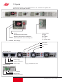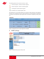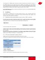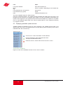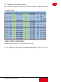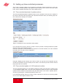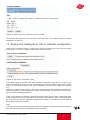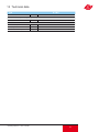
1
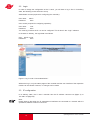
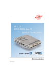
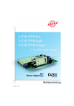
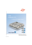
Operating instructions
U 100-C Controller
General
This operating manual was created to provide the relevant instructions for operating the U100-C.
We expressly recommend reading this manual before installing or operating the device.
The ASTRO company confirms the information in this manual to be correct at the time of printing,
but it reserves the right to make changes, without prior notice, to the specifications, the operation of the device and the operating manual. The ASTRO company is not responsible for printing
errors. The contents of this operating manual are confidential and protected by copyright. This
manual may not be reproduced in any form - not even in part - without prior written permission
from the ASTRO company.
Pictograms and safety instructions
Pictograms are visual symbols with specific meanings. You will encounter the following pictograms in this installation and operating manual:
Warning about life-endangering situations due to dangerous electrical voltage or non-adherence
to this manual.
Warning about various dangers to health, the environment and material.
Recycling: all of our packaging material (cardboard boxes, accompanying papers, plastic film and
bags) is completely recyclable.
Used batteries must be disposed of at approved recycling points. Batteries must be completely
discharged before being disposed of.
Electronic devices must not be disposed of with household waste, but rather – according to directive 2002/96/EG OF THE EUROPEAN PARLIAMENT AND OF THE COUNCIL from 27 January
2003, on waste electrical and electronic equipment – must be properly disposed of. When they
are no longer of use, please bring these devices for disposal to one of the public collection points
for this purpose.
Copyright notice
Some of the software for this product is third-party software, which was developed under several
different licensing conditions. Detailed information concerning the licenses can be found via the
Web interface of the device.
The source code of the free parts of the software is distributed on request for an administration
fee.
Please contact:
[email protected]
ASTRO Strobel Kommunikationssysteme
Olefant 1-3
D-51427 Bergisch Gladbach (Germany)
Tel.: +49 2204 405/-0
All other parts of the software of this product are copyrighted by Astro Strobel Kommunikationssysteme GmbH.
© Copyright 2011 by Astro.
2
Operating Manual U 100-C Controller
Table of contents
1 Figures .........................................................................................................................................................4
2
Introduction ........................................................................................................................................5
2.1
Description of functions .....................................................................................................................5
2.2
Safety instructions .............................................................................................................................5
2.3
Mounting instructions ........................................................................................................................5
2.4
Potential equalisation / earthing ........................................................................................................6
2.5
Maintenance and repair ....................................................................................................................6
2.6
Service tasks .....................................................................................................................................6
2.7
Technical data for the mains supply (U 100 SNT - 230 V version) ..................................................6
2.8
Installing and coding the backplane ..................................................................................................7
2.8.1
Coding the backplane .......................................................................................................................7
2.8.2
Installing the backplane .....................................................................................................................8
3
General introduction ..........................................................................................................................9
3.1
Connecting the U 100-C to a PC / laptop .........................................................................................9
3.2
Log in...............................................................................................................................................10
3.3
IP configuration ...............................................................................................................................10
3.4
Time configuration ...........................................................................................................................11
3.5
Setting up a user / Rights management / Log-in timeout ...............................................................12
3.6
Logging the controller in to the U 1xx signal converter...................................................................14
3.7
Assigning system names ................................................................................................................14
3.8
Adding U 1xx signal converters to the configuration.......................................................................15
3.9
Removing U 1xx signal converters from the configuration .............................................................15
4
Overview of the headend ................................................................................................................16
4.1
Status display ..................................................................................................................................16
4.2
Output channel overview / Channel overview .................................................................................17
4.3
Material overview / Inventory report ................................................................................................17
5
Log files ...........................................................................................................................................18
5.1
Setting event filters in the system log file........................................................................................18
5.2
Saving and deleting the system log files .........................................................................................19
6
Headend module settings / Module settings ..................................................................................20
6.1
Active headend module settings / Active settings ..........................................................................20
6.2
Stored headend module settings / Stored settings ........................................................................20
6.3
Uploading locally stored module settings / Upload settings............................................................21
6.4
Monitoring the configuration / Configuration monitoring .................................................................22
7
Switching equivalent head-end module circuits / Replacement ......................................................23
7.1
Manual switching to equivalent circuits ...........................................................................................23
7.2
Removing an equivalent circuit .......................................................................................................24
7.3
Automatic equivalent circuit ............................................................................................................24
7.4
Defining output segments / Output segments .................................................................................25
8
SMNP settings.................................................................................................................................26
9
Updating ..........................................................................................................................................27
9.1
Uploading locally stored update archives to the U 100-C controller ...............................................27
9.2
FTP server download of update archives .......................................................................................27
9.3
Displaying available update archives ..............................................................................................28
9.4
Updating U 1xx headend modules ..................................................................................................29
10
Setting up time-controlled processes ..............................................................................................30
10.1
FTP server download of update archives .......................................................................................30
10.2
11
12
13
Time-controlled update of U 100 headend modules .......................................................30
Storing and loading the U 100-C controller configuration ...............................................31
Controller restart / Reset .................................................................................................32
Technical data .................................................................................................................33
Operating Manual U 110-C Controller
3
1 Figures
The figures show the U 100-C installed in the U 100 - 230 base unit together with
the U 114 IP / PAL signal converters.
Control
and data wheel, menu switch
Display of management IP addresses,
data IP addresses, status messages, etc.
Status display
for slots
L = left
M = middle
R = right
P = power supply
Status display
Data ports
HF outputs
Fan
230 V power unit
Mains supply
Earthing connection
Mains supply
Management ports
48 V power unit:
Cutout switch
Mains supply
Earthing connection
4
Operating Manual U 100-C Controller
2
Introduction
The instructions in chapter 2 mainly apply to the U 100 - 230 base device.
2.1
Description of functions
The U 100 series is used to convert IP data streams into CATV signals. The U 100-230 base
device can accommodate up to three U 1xx signal converters, as well as up to two U 100-SNTs
for supplying the voltage to the U 1xx signal converters. The U 100-C is used for comprehensive
system management for the U 1xx signal converter, and provides many functions for configuring
and servicing the U 100 series.
2.2
Safety instructions
Disconnect both mains plugs before opening the device!
The device must not be opened - for exceptions, see the maintenance and repair, and the service
tasks! Power supply units must not be opened!
The device must be connected to a power supply with an earth contact, and should be positioned
close to the mains socket.
The electrical system supplying current to the device, e.g. a house installation, must incorporate
safety devices against excessive current, short-circuiting and earth leakages in accordance with
EN 60950-1.
Both mains plugs are used to disconnect the device from the mains, therefore they must be
easy to access and use at all times. The device is already in operation when one power unit is
connected to the operating voltage. When the second power unit is also put into operation, one
of the power units runs in idle mode as long as the other unit is supplying power to the device.
The device may only be repaired by sending it to ASTRO along with a precise description of the
error.
Displays indicate the status of the device operation, as well as the existence of DC voltages
separate from the mains that are supplying the components of the device. However, operation
displays that are not lit up in no way indicate that the device is completely disconnected from the
mains or is voltage-free.
Read carefully:
EN 60 728 – Part 11, Safety requirements / No service tasks during electrical storms!
2.3
Mounting instructions
The U 100 base device may only be mounted using guide rails! If the device is only fastened by
means of the screws in the front panel, this will damage the base device!
The outputs of the signal converter must not be operated without connecting a combining network
or terminating impedance!
Protection from environmental factors:
The device must only be connected and operated in dry rooms. It must not be exposed to spraying or dripping water, or to similar phenomena. If condensation appears, wait until the device is
completely dry. Objects containing liquid must not be placed on top of the device.
The permitted ambient temperature range is 0 … 45°C (ETS 300 019-1-3 class 3.1).
Mounting environment:
The device is designed for operation in, preferably, metallically conductive 19" racks with sufficient air convection. It should be operated away from heat radiation and other heat sources. The
device my only be installed in rooms in which the permitted ambient temperature can be adhered
to, even under changing climatic conditions. To avoid trapped heat, it must be freely ventilated
on all sides. You absolutely must avoid mounting the device in a niche or covering the ventilation
openings.
Operating Manual U 110-C Controller
5
2.4
Potential equalisation / earthing
The subscriber network must be earthed correctly in accordance with EN 50083-1, and must
remain earthed even when the device is removed.
The potential equalisation on the U 100 is effected via the fastening plates of the device, or
via the earthing connection on the back of the device. Devices within hand's reached must be
incorporated into the potential equalisation among one another.
It is not permitted to operate the device without an earth conductor, device earthing or device
potential equalisation!
2.5 Maintenance and repair
Disconnect both mains plugs before opening the device!
The device must not be opened other than for repair purposes. In general, power units must
not be opened. Repairs may only be carried out at the plant or at workshops, or by persons,
authorised by ASTRO Strobel Kommunikationssysteme GmbH.
Read carefully: DIN VDE 0701- 0702, Repairs
Note: The device must not be opened by the user!
2.6 Service tasks
The following tasks, in which screw connections have to be opened, can be performed by appropriately instructed service personnel: Removal and installation of signal converters (e.g. U 114)
and power units, also when the U 100 is in operating mode.
Replacing power units
After the screws on the cover of the power unit chamber (ASTRO logo) are removed,
the power units can be pulled out by hand, forwards along the mounting panel.
When power units are being installed, there should be no contact with the ventilator or the fan
grid,
and only the mounting panel attached to the power unit should be used.
When the tasks are complete, the cover of the power unit chamber must be replaced;
continuous operation of the device is not permitted without this cover.
Note: Do not put your hand or any objects into the power unit chamber.
The U 100 must only be operated with the original power unit(s)!
Replacing converter modules:
Converter modules can be pulled outwards after the safety screw on the front panel
has been unscrewed.
2.7 Technical data for the mains supply (U 100 SNT - 230 V version)
Mains voltage:
Mains frequency:
Current consumption:
Protection class according to EN 60529:
Permitted ambient temperature range:
Secondary fuse in U100-230:
Secondary fuses in U114:
6
100 – 240 V
50 / 60 Hz
1.4 – 0.7 A per power unit
IP 20
0 … 45 °C
T3,15A L 250 V IEC 60127-2/3
SMD, various values
Operating Manual U 100-C Controller
2.8
Installing and coding the backplane
The scope of delivery of every U 1xx signal converter includes a backplane to create the physical
connection between the signal converter and the base device. Both the mains HF connections
and the network connections are connected to this backplane. The temperature controlled fan for
cooling the U 1xx signal converter is located on the backplane.
2.8.1 Coding the backplane
To correctly define the position of the backplane, and thus the position of the related signal converter in the U 100 base device, the jumper on the board of the backplane, which is described in
the following section, must be configured.
Left
Jumper position
left!
Middle
No jumper!
Right
Jumper position
right!
Figure 1: Coding the backplane using the jumper
Note:
An incorrectly configured jumper leads to incorrect displays in the front LEDs.
In addition, it is not possible to display a correct position on the Web user interface!
Operating Manual U 110-C Controller
7
2.8.2 Installing the backplane
In its state on delivery, the back of the U 100 base device is covered with blind panels:
Phillips
screws
Figure 2: Position of the blind panel on delivery of U 100
To remove the blind panel, unscrew the two Phillips screws indicated in the above figure and
remove the blind panel. The cables now visible must be connected to the backplane coded
according to chapter 2.8.1, as shown in the following figure:
Figure 3: Connecting the voltage supply and signal lines
The backplane is now carefully inserted into the free slot of the U 100 base device and screwed in
with the Phillips screws of the backplane. When doing so, ensure that the cables are not jammed
and that the backplane can be installed in the housing with only a small amount of pressure.
Figure 4: Correctly installed backplane
8
Operating Manual U 100-C Controller
3
General introduction
3.1 Connecting the U 100-C to a PC / laptop
When the operating voltage is applied, or after insertion in the slot of the base unit,
the U 100-C switches itself on automatically. Following a boot phase (approx. 90 seconds),
the ASTRO logo appears in the display. The page “Network/Rack”, on which the IP addresses
appear, is accessed by turning the control knob. If the device is connected to a PC / laptop via
one of the network ports, and if the PC / laptop is suitably configured via the network settings, you
can start configuring the U 100-C after you enter the IP address in the address line of the web
browser. The IP address is 192.168.1.70 (Mgmt A) or 192.168.5.70 (Mgmt B) in delivery state.
After activating the IP address, a window appears as in the following example:
Title bar
Main window
U 100-C menu
Figure 5: Example view of the web browser interface before configuration
The controller status appears on the left side of the screen, with the so-called rack view appearing
underneath it, which reflects the view of the head end. Clicking on the required module in this rack
view allows the respective module to be configured. The links from “Log in” to “User manual” lead
to overview pages, and to the configuration of the controller explained in the following.
The heading for the sub-item selected appears in the head line. Furthermore, the date, the time
(UTC), the uptime, the software version and the hardware version appear here. There is the
option of entering a name, location and contact address. This is done in the sub-menu “SNMP”.
The display in the main window corresponds to the sub-menu selected. These could be overview
pages (status, channel overview & inventory report), or controller configuration pages, or user
interfaces for the respective signal converter U 1xx which has been selected.
Operating Manual U 110-C Controller
9
3.2 Login
In order to change the configuration of the U 100-C, you will have to log in first. In its delivery
state, the following access has been set up:
Administrator access (required for configuring the controller):
User name:
Password:
admin
astro
User access (required for configuring operation):
User name:
user
Password:
astro
You must log in before the U 114 can be configured. This is done in the “Login” submenu.
In the state on delivery, the login data is as follows:
User: admin or user
Password:
astro
Figure 6: Log in under “User authentication”
Without the log in, only the status pages of the controller and the user interface of the respective
module can be viewed. However, no changes can be made.
3.3 IP configuration
In its delivery state, the U 100-C controller has the IP address 192.168.1.70 (Mgmt A) or
192.168.5.70 (Mgmt B).
Note:
Please observe that when the IP management interfaces are connected to a network which is
operational, address conflicts could occur.
10
Operating Manual U 100-C Controller
Figure 7: Example view of the “Network settings”
After successfully logging in, the network settings can be configured. These settings are:
IP address (address), sub-network mask (netmask) and standard gateway (gateway).
Changes are applied using the “Submit” button. Depending on the new allocation of the IP
addresses, it may be necessary to adapt the IP settings of the PC / laptop to ensure access to
the controller is possible.
3.4 Time configuration
The U 100-C controller provides the option of configuring the system time. Observe that UTC
(Universal Time Coordinated) is always used as a reference.
The date is entered in the column “Day”, the month in the column “Month” and the year in the
column “Year”. The time is entered in the column “Hour”, “Minute” and “Second”.
The settings are applied using “Submit”. An unwanted setting can be reset using the “Reset
form” button. In this case, the previous settings are displayed again.
Along with manual time input, an NTP time server can be entered. If the configuration is valid,
the time is received from this server. To set up this server, enter the IP address and press the
“Add” button (+) in the column “Action”. Any NTP server already set up can be removed using
(-).
Operating Manual U 110-C Controller
11
Figure 8: Setting the system time
3.5 Setting up a user / Rights management / Log-in timeout
The sub-menu “User administration” is used to set up users, assign user rights and set the log-in
timeout.
Figure 9: View of the user administration
In delivery status, one user and one administrator have been set up on the U 100-C (admin: user
name = admin, PW = astro, and user: user name = user, PW = astro, see chapter 3.2, Log in).
12
Operating Manual U 100-C Controller
A new user is set up in the first blank line underneath any users already created (e.g. line 3 in figure 9). The user name is entered in the column “User”, the rights assigned in the column “Access”
and the password is entered in the column “Password”. This password must be entered a second
time in the column “'Retype password”.
In the user administration, the user will encounter the following pictograms:
=Edit user
= Accept changes
= Remove user
= Add user
Without log in:
View of the status pages for the headend (status, channel overview and inventory report as well
as log file and user manual) and view of the respective U 1xx signal converter, however without
the option of changing settings.
User log in:
Operation and reconfiguration of the signal converter (no change to the IP settings), load / save /
copy module settings to “Module settings”, equivalent circuit (replace) and update.
Admin log in:
Access to the configuration (sub-menu “Configuration”) for the headend, or e.g. adding or removing further modules and access to the IP settings of the controller (sub-menu “Network/Rack”).
SNMP settings (sub-menu “SNMP”), creating and removing users in the sub-menu “Users”,
changing the timeout.
Changing all controller settings; access to all sub-menus. Full access to the signal converter U
1xx. The management IP addresses for the signal converter cannot be changed using the controller.
Note:
The management IP addresses for the signal converter can only be changed after this converter
has been removed from the controller configuration (see chapter 3.9) and direct access is made
via the IP address of the signal converter.
The timeout can be configured to between 1 minute and 59 minutes. This value is changed using
the “Submit” button. The input can be reset again using “Reset form”. The previous value set then
reappears.
Operating Manual U 110-C Controller
13
3.6 Controller log in to the U 1xx signal converter
To ensure the controller can log in to the U 1xx signal converter for the headend, the module dialin parameters of the controller configured in the U 100-C must match the dial-in parameters in
the U 1xx signal converter. In default state, two accounts for the module log in have been set up:
User account: user name: controller / password: astro
Admin account: user name: admin / password: astro
Figure 10: Module log in
Each of these two accounts have also been set up as default settings on each U 1xx
signal converter.
Note:
Changes to these account must also be made in the U 1xx signal converters. Otherwise, the U
100-C controller cannot log in to the U 1xx signal converter.
3.7
Assigning system names
In the sub-menu “SNMP” the system names appearing the head line can be entered. These
are “Name” (e.g. name of the network operator), “Location” (e.g. location of the head line) and
“Contact” (e.g. contact person for the respective headend). The values entered here are not only
visible in the table, but are also used as SNMP system information (see chapter 8, “SNMP”).
Figure 11: Entry of the system information
14
Operating Manual U 100-C Controller
3.8 Adding U 1xx signal converters to the configuration
Note:
Before signal converters U 1xx can be incorporated in the configuration for the U 100-C, it must
be ensured that all U 1xx feature different management IP addresses, and all base unit addresses
for the U 100-230 / -48 feature different values (see operating manual for the signal converter U
1xx). If this is not the case, then not all modules will be imported into the configuration.
Figure 12: View of the point “configuration” without modules added
Using the example in figure 11, you can see how the table is structured using the configuration
view without the signal converter U 1xx added:
Column “Base”: display of the base unit address; column “Slot”: display of the slot; column “IP
address”: display of the IP address of the respective module; column “Description”: information on
the module type; column “Action”: button for removing the respective module from the configuration; column “Monitoring”: display of the module status.
A module can be added under “Add modules” (fig. 13) by entering individual IP addresses, several
IP addresses separated by a space, or an automatic search of a sub-network by the controller. If
a search for a sub-network should be made in this form, then the address range must be entered
in CIDR notation.
CIDR notation means:
Entry of the network address separated by a “/” from the suffix entered. The suffix
specified the number of bits set in the network mask. For the example, this means:
192.168.1.0 as the network address and 255.255.255.0 for the sub-network mask
(binary: 11111111 11111111 11111111 00000000) with 24 bits set.
Figure 13: Screen for entering the IP addresses of modules to be added
3.9 Deleting U 1xx signal converters from the configuration
To remove modules form the configuration of the U 100-C, the “Remove module from configuration” button in the column “Action” must be pressed (see figure 13).
Figure 14: Button for removing modules from the configuration
Operating Manual U 110-C Controller
15
4
Overview of the headend
To simplify the overview of the modules connected to the U 100-C, the U 100-C features several
overview pages. These overview pages can be accessed without logging in to the U 100-C controller. Changes to the configuration are not possible here.
4.1 Status display
The status display can be accessed using the link “Status” in the left frame of the web browser
user interface. The following view, an example, opens:
Figure 15: Display of the headend status
The details of the individual modules can be viewed using the plus sign in the column “Base”. The
details on the status of the module concerned are displayed here (see figure 16).
Figure 16: Status details
16
Operating Manual U 100-C Controller
4.2 Output channel overview / Channel overview
In the output channel overview, all output channels and frequencies used are listed, beginning
with the lowest frequency. Using this overview, the output channels can be linked with the services converted and the slot of the U 1xx signal converter.
Figure 17: Example of output channel overview / channel overview
4.3 Material overview / Inventory report
Using the material overview, which is accessed using the link “Inventory report” on the left side of
the web interface screen, an overview can be gained of the modules of which the entire headend
is comprised, and in which base unit – on which slot – which unit – is being used.
In addition to this information, the order number of the respective module is specified in the column “Order no.”.
Operating Manual U 110-C Controller
17
Figure 18: Example of material overview / inventory report
The hardware status of the respective device appears in the line “HW”, and in the line “SW”, the
software status is shown. The “Uptime” is the length of time for which the device has been in
uninterrupted operation. The line “Monitoring” specifies the status.
5
Log files
The log files can be accessed using the link “Log file”. In the system log file, all relevant processes concerning operation are recorded. Further log files can be downloaded:
Download log file:
Replacement log file:
Update log file:
Logs for downloads from update archives
Logs for equivalent circuits
Logs for updates
5.1 Setting event filters in the system log file
To manage the displayed entries in the log file, filters can be used to select which events are displayed. This is set in
the line “Filter”. Activating the check box results in a display of an event with the respective severity level. An entry will
be made in the log file.
Figure 19: Event filter in the log file (delivery state)
18
Operating Manual U 100-C Controller
5.2
Saving and deleting the system log files
The log file can be stored using the “Save” button. The file with the content of the log file is generated as “system.log” as standard and can be viewed e.g. using an editor.
The “Clear” button ensures that the system log file is deleted and that the entry “Log file cleared”
appears in first place.
Figure 20: Example view of the system log file page
Operating Manual U 110-C Controller
19
6
Head end module settings / Module settings
The headend module settings can be accessed using the link “Module settings” on the left side
of the web interface screen. On the U 100-C, a general distinction is made between active and
saved module settings.
6.1 Active head end module settings / Active settings
In the upper section of the sub-menu “Module settings”, the active headend module settings are
displayed. The structure of the overview is similar to the way the headend is structured, by base
unit (column “Base”), slot (column “Slot”) and module type (column “Module”).
Figure 21: Excerpt from the active settings of an example base unit
Furthermore, the IP addresses are displayed, the names of the files (column “Name”) and the
date of the last change to the settings (column “Date”). In the column “Action” the diverse buttons
explained in the following are available.
= “Reload from Module”: re-import of the module data in the controller
= “Upload to Module”: re-writing of the active settings
= “Save to stored settings”: saves the active settings to the
“Stored settings” field.
Figure 22: Buttons in the “Active settings” field
When the “Save to stored settings” button is pressed, an entry is made in the “Stored settings”
field. A name is given according to the IP address management A formula: aaa.bbb.ccc.ddd.zip,
can however be subsequently edited (see chapter 6.2).
6.2 Stored head end module settings / Stored settings
In the “Stored settings” field, the settings saved by the user for the respective headend modules
can be found. In this view, all module configurations which were loaded to the controller manually
are also displayed.
Figure 23: Example view of the “Stored settings” field
20
Operating Manual U 100-C Controller
To write stored module settings into an active headend module, the radio button in the first column
of the saved setting required must be activated as well as the radio button in the first column in
the “Active settings” field on the module required. The settings are written into the module using
the “↑Activate” button.
A graphic example showing a U 114 IP / PAL converter:
Figure 24: Example for writing stored settings in active mode
In the column “Action” the diverse buttons explained in the following are available.
= “Rename Settings”: changes the name of the configuration
= “Download Settings”: downloads the configuration / saves it locally
= “Remove Settings”: deletes the stored settings from the controller
Figure 25: Buttons in the “Stored settings” field
6.3 Uploading locally stored module settings / Upload settings
There is an option of uploading locally stored module settings onto the controller. This is done in
the “Upload settings” field.
Figure 26: Dialogue field “Upload settings”
Using the “Search” button, a file-upload window is opened in which the selection of the configuration for upload is made.
A successfully uploaded file is then displayed in the “Stored settings” field and can then, as
described in chapter 6.2, be loaded to the headend module.
Operating Manual U 110-C Controller
21
6.4
Monitoring the configuration / Configuration monitoring
In ongoing operation, the controller monitors the configuration of the modules. If the configuration
of a module does not match the configuration filed under “Active settings”, then different procedures can be defined:
Figure 27: Procedure when detecting “configuration not in sync”
When the option “Warning” is used, only the warning “config not in sync” is issued, however no
operative action is taken. If the option “restore replaced modules only” is selected, then the configuration is only reloaded to the module for equivalent-circuit modules (default). The third option
is “restore always”, and every time a “configuration not in sync” is detected, the configuration will
be reloaded to the module.
The “Restore” function is equivalent to the same action as a manually-performed “Upload to
module” (see chapter 6.1).
22
Operating Manual U 100-C Controller
7
Switching equivalent head-end module circuits /
Replacement
The U 100-C controller provides an option of manually or automatically switching the replacement
module kept in the headend to an equivalent circuit. The settings for this equivalent circuit can be
accessed using the link “Replacement” in the left screen side of the web interface.
7.1 Manual switching to equivalent circuits
Switching to an equivalent circuit manually is done in the “Replace” field. The options for the
equivalent circuit are displayed here. A headend module is then identified as a replacement mod
module by the U 100-C controller, if the HF outputs are configured to “Off”.
Figure 28: Example view of the “Replace” option
The modules deactivated on the HF are backlit in grey in the column “Status” in the view in figure
27, and their status is “off”. Each of these replacement modules are available for selection in the
column “Replace options”. Prerequisite for this is that the outputs in the same cable network have
been bundled (see chapter 7.3 Output segments). To establish the equivalent circuits, the radio
button in the required equivalent circuit option must be selected, and the “Replace” button must
then be pressed. The U 100-C controller then establishes the equivalent circuit automatically. This
process is documented in the Replacement log file. The module used for the equivalent circuit will
not appear in the column “Replace options” until the equivalent circuit is removed.
Operating Manual U 110-C Controller
23
7.2 Removing an equivalent circuit
An active equivalent circuit can be identified in the “Replace” display, as in the following example:
Figure 29: View of an equivalent circuit
After rectifying a fault or e.g. replacing a module, the equivalent circuit can be reversed. This is
done by activating the radio button “undo replacement” in the column “Replace options” and then
pressing the “Submit” button. This procedure is necessary, regardless of whether the equivalent
circuit was set up manually or automatically. The U 100-C controller undoes the equivalent circuit
if the operating module can be restarted without a fault. This process is also documented in the
Replacement log file.
7.3 Automatic equivalent circuit
Figure 30: Conditions which must be activated for an automatic equivalent circuit
24
Operating Manual U 100-C Controller
The U 100-C controller provides the option, depending on the fault which has occurred, of establishing an equivalent circuit for the U 1xx signal converter. The conditions for this equivalent circuit
are listed in figure 30 and vary depending on which U 1xx signal converter is in use. The selection
is applied by pressing “Submit”.
Note:
Activating the options with *) should be given good consideration, as these fault patterns do not
necessarily correspond to a signal failure, but rather may also indicate that the U 1xx signal converter cannot be reached. It is quite possible that these modules are still sending an HF output
signal, and that in the event of an equivalent circuit a double allocation in the output channel will
occur.
7.4 Defining output segments / Output segments
The individual headend modules can, in theory, be combined in different networks. This means
that the U 100-C controller must know in which network or which output segment the output signal
is distributed. If this were not the case, then an equivalent circuit – without allowing for the output
segments – could cause double channel allocations in the respective networks. In the example
below, the replacement modules no. 6 can only replace module no. 5 as the physical HF wiring
only fits together with module no. 5.
Figure 31: Combining example with restricted equivalent circuit options
Output segments can be created in the sub-menu “Configuration” which is accessed using the link
of the same name in the left frame of the web interface.
Figure 32: Creating different network segments
In the first column in the section “Output segments”, the consecutive number of the output segment is displayed, in the column “Segment name”, the name of the respective network segment
is displayed.
Operating Manual U 110-C Controller
25
The following buttons can be used in the column “Action”:
= “Rename segment”: renames the network segment
= “Remove segment”: removes a network segment
= “Add segment”: adds a network segment
Figure 33: Buttons in the “Output segments” field
After defining one or more output segments, the column(s) “Output segments” will be added to
the table in the “Configuration” field. The output segments can now be selected by activating the
check boxes for the respective output segment used. The selection is applied by pressing “Submit”.
Figure 34: Example view once output segments are defined
8
SMNP settings
Figure 35: SNMP settings page in delivery state
26
Operating Manual U 100-C Controller
The settings in the “SNMP System information” field have already been described in chapter 3.7.
The SNMP settings can be accessed using the link “SNMP on the left side of the web interface
screen. The page which then opens is shown in figure 35. Along with the SNMP system information, SNMP trap receivers can also be set up. To do so, enter the IP address of the trap receiver
and then use the “Add trap sink” button to copy this into the column “Action”.
In the SNMP MIBs field both the ASTRO Strobel MIB as well as the AstroStrobel-Edge-CTRL
MIB can be downloaded.
9
Updating
All information on updating the U 1xx signal converter and the U 100-C controller itself can be
found in the sub-menu “Update”. The sub-menu can be accessed using the link “Update” in the
left frame of the web browser user interface.
9.1 Uploading locally stored update archives to the U 100-C controller
To ensure that the U 100-C controller can update the U 1xx signal converter in use, the update
archive required must first be copied onto the U 100-C controller. This can be done using the
locally-stored archive, or using an FTP server download (see chapter 9.2).
Figure 36: Dialogue field “Add archive”
Using the “Search” button, a file-upload window is opened in which the selection of the archive for
upload is made. A valid archive must be selected, as the controller checks the file and discards
any invalid files.
After successfully uploading, the update archive appears in the “Update archives” field and is
available as an option for an update in the “U 100 headend update” field in the column “Update
options” on the respective matching U 1xx signal converter.
9.2 FTP server download of update archives
Update archives can alternatively be downloaded from an FTP server.
This feature is explained in the following using the ASTRO firmware server as an example:
Figure 37: Input screen for downloading update archives from the server
Operating Manual U 110-C Controller
27
Line:
Input:
FTP Server address
Mode
ting
FTP Username (e.g. anonymous)
FTP Password (e.g. guest)
Path
www.astro-firmware.de
Active or passive, depending on the Firewall setAnonymous
Guest
/Headend-Firmware/u1xx/
The entry is applied using the “Submit” button.
Using the “Download” button, any update archives available are loaded from the server. This
process can also be done to a schedule (see chapter 10). After successfully downloading, the
update archive appears in the “Update archives” field and is available as an option for an update
in the “U 100 headend update” field in the column “Update options” on the respective matching
U 1xx signal converter.
9.3 Displaying available update archives
Available updates are displayed on the U 100-C controller in the “Update archives” field. In its
delivery state, the U 100-C is equipped with an SD card. Memory space remaining on this card is
indicated under “SD card memory”.
= “Archive info”: version information on SW releases
= “Archive download”: archive download and local
Saving this downloaded archive
= “Remove archive”: removes the archive from the U 100-C
Figure 38: View of the available archives on the U 100-C / buttons
28
Operating Manual U 100-C Controller
9.4 Updating U 1xx headend modules
After successfully uploading the update archive, these are available for updating the diverse U
1xx headend modules or the U 100-C. (see fig. 39).
Figure 39: Example view of the “U 100 headend update” field
After selecting the action(s) to carry out, the update can be started by pressing the “Update” button. The “Reset form” button resets the action selected beforehand. This process can also be
done to a schedule using the “Schedule update(s)...” button (also see chapter 10).
Operating Manual U 110-C Controller
29
10 Setting up time-controlled processes
The U 100-C controller is able to run processes to a schedule. These processes are, on the one
hand, a time-controlled update of the update archives found on the U 100-C, and on the other
hand, a time-controlled download of the same update archive.
10.1 Time-controlled download of update archives
The time-controlled download of update archives can be activated in the sub-menu “Update” in
the “Server download” field. By pressing the “Schedule download” button, the following input window, shown as an example, is accessed:
Figure 40: Setting up a time-controlled, weekly update
In the example shown above, after the “Confirm” button is pressed, a weekly download of update
archives occurs, every Monday at 07:55.
If the link “Schedule” is now pressed in the left frame of the web interface, then the scheduled
download which has been set up is displayed:
Figure 41:
Using the “Disable process” button in the column “Action”, the process can be stopped any time
and then be restarted using the “Enable process” button. The “Remove process” button removes
the process from the overview.
10.2 Time-controlled update of U 100 head end modules
The time-controlled update of U 100 headend modules is made in the sub-menu “Update” in the
“U 100 headend update” field. To do this, each respective module for which a time-controlled
update should be made must be marked using the radio button in the column “Update options”,
and then by pressing the “Scheduled update(s)” button on it.
In the following example, after the “Confirm” button is pressed, a one-time, non-recurring update
of a U 114 IP / PAL signal converter occurs:
30
Operating Manual U 100-C Controller
Figure 42: Setting up a time-controlled, one-time update
This process also appears in the sub-menu “Schedule” and can be edited using the buttons
described in chapter 10.1.
11 Storing and loading the U 100-C controller configuration
Using the link “Load/save config” in the left frame of the web interface, the sub-menu for storing
and loading the U 100-C controller configuration can be accessed.
Figure 43: Sub-menu “Load/Save config”
If the “Save” button is pressed in the “Save controller configuration” field, then the U 100-C controller configuration is saved. The file is automatically named according to the formula “Name
(city).conf”. The variables “Name” and “City” are assigned in the sub-menu “SNMP” (see chapter
3.7).
When the “include module log files” check box is activated, both the controller configuration as
well as the log file for the U 1xx headend modules are downloaded. This information can be evaluated at Astro for debugging purposes.
In the “Load controller configuration” field the backed up, locally saved U 100 C configuration data
can be exported into the controller. When securing these files, both the user accounts as well as
the IP settings are secured. When the configuration is loaded, it is possible to choose whether
these data should also be copied.
Note:
If the user accounts and network settings should be overwritten along with the specific configuration, then this may result in the headend being unreachable.
Operating Manual U 110-C Controller
31
12 Controller restart / Reset
To restart the controller or to reset it to the factory default settings, you must switch to the corresponding sub-menu using the link “Restart/reset” on the left edge of the web interface. The
following input mask appears:
Figure 44: Input mask for controller restart/reset
Selecting “Restart” will reboot the device, while retaining all settings.
Selecting “Soft reset” deletes the current configuration of the U 100-C. The network settings and
user accounts will be retained.
Selecting “Hard reset” restores the delivery state, i.e. the U 100-C configuration, the network settings and user accounts will be deleted.
Note:
Selecting “Hard reset” may lead to the headend being unreachable by remote access.
32
Operating Manual U 100-C Controller
13 Technical data
Type
U 100-C
Order number
380 103
Network interfaces (forwarded passively to U 1xx)
Protocol
IEEE802.3 Ethernet, RTP, ARP, IPv4, TCP/UDP, HTTP, SNTP, IGMPv3
General data
Power consumption
[W]
Housing
Permitted ambient temperature
Operating Manual U 110-C Controller
27
19", 1 HE
[°C]
0...+45
33
34
Operating Manual U 100-C Controller
Operating Manual U 110-C Controller
35
82444 400 10/2011
ASTRO Strobel Kommunikationssysteme GmbH
Olefant 1–3, D-51427 Bergisch Gladbach (Bensberg)
Tel.: 02204/405-0, Fax: 02204/405-10
eMail: [email protected], www.astro-kom.de
Operating Manual U 100-C Controller