1
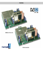
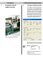
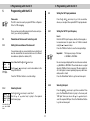
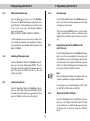
X-QAMtwin 5 S2 / 6S2 / V 502
Operating Instructions
Illustrations
X-QAM twin 5 S2 / twin 6 S2
V 502 with channel filter
Contents
Contents
Illustrations
1
2
3
Pictograms
Programming with the KC 3 . . . . . . . . . . . . . . . . . . . Page11
5.1
. . . . . . . . . . . . . . . . . . . . . . . . . . . . . . . . Page 4
Description . . . . . . . . . . . . . . . . . . . . . . . . . . . . . . . . Page 4
5.2
Pre-configuration / wiring . . . . . . . . . . . . . . . . . . . . . Page 5
Programming with the HE programming software . . Page 5
3.1
Activation of the NIT generation
3.4
Checking the input signal quality . . . . . . . . . . . Page 7
3.5
3.6
3.7
3.8
3.9
5.3
Programming the card parameters . . . . . . . . . . Page 6
5.2.4 Adjusting the DVB search mode . . . . . . Page12
Setting the RF output parameters . . . . . . . . . . Page12
5.3.1 Setting the RF output parameters . . . . . Page12
5.3.5 Inverting the spectrum . . . . . . . . . . . . . . Page13
Error messages . . . . . . . . . . . . . . . . . . . . . . . . Page 8
5.3.6 Error messages . . . . . . . . . . . . . . . . . . . Page13
Inputting the Operator ID . . . . . . . . . . . . . . . . . Page 9
Saving . . . . . . . . . . . . . . . . . . . . . . . . . . . . . . . . Page10
5.2.1 Adjusting the SAT IF input frequency . . . . . Page11
5.3.4 Switching off the output signal . . . . . . . . Page13
PID remapping . . . . . . . . . . . . . . . . . . . . . . . . . Page 8
4.3
Adjusting the SAT input parameters . . . . . . . . . Page11
5.3.3 Setting the modulation type . . . . . . . . . . Page13
Setting the PID filters . . . . . . . . . . . . . . . . . . . . Page 8
5.3.7 Equalizing the levels
of the X-QAM twin 5 S2 /
Fundamentals for programming with the KC 3 . . . Page10
4.2
5.1.2 Selecting a slot . . . . . . . . . . . . . . . . . . . . Page11
5.3.2 Setting the output data rate . . . . . . . . . . Page12
Level equalization . . . . . . . . . . . . . . . . . . . . . . . Page 7
Structure . . . . . . . . . . . . . . . . . . . . . . . . . . . . . . Page10
5.1.1 Setting the bus address . . . . . . . . . . . . . Page11
5.2.3 Setting the symbol rate . . . . . . . . . . . . . . Page12
. . . . . . . . . . . Page 6
4.1
Base unit parameters / selecting a slot . . . . . . Page11
5.2.2 Selecting the input . . . . . . . . . . . . . . . . . Page11
Pre-configuration of the HE programming software . Page 5
3.2
3.3
4
. . . . . . . . . . . . . . . . . . . . . . . . . . . . . . . . Page 2
5
X-QAM twin 6 S2 and V 502 cards . . . . Page13
Programming sequence . . . . . . . . . . . . . . . . . . Page10
6
3
7
5.3.8 Output channel filter (V 502 only)
. . . Page13
Technical data . . . . . . . . . . . . . . . . . . . . . . . . . . . . . . Page14
Summary of programming steps . . . . . . . . . . . . Page15
Pictograms
1
Pictograms and safety information
Pictograms are symbols which have a defined meaning. You will encounter the following pictograms in
these operating and installation instructions:
This symbol is used to warn about situations in which
there is a risk of fatal injury due to dangerous electrical voltages or as a result of failure to comply with
these instructions.
This symbol is used to warn about various risks to
health, equipment/materials or the environment.
Recycling symbol: all of our packaging materials (cardboard packaging, package inserts, plastic film and plastic bags) can be fully recycled.
1 Description
Description
The X-QAM twin x S2 and V 502 cards are used to convert
two DVB-S modulated SAT IF signals into two QAM modulated neighboring channels in the frequency range from 47
to 862 MHz. They can process both HDTV signals and
SDTV signals. The signal conversion of the X-QAM twin x
cards is realized with Direct Digital ® - technology. Both
output channels can be switched on or off independently of
each other. The level equalization of the individual plug-in
cards to the same output level is performed via an electronic
level equalization control either via the HE programming
software or via the KC 3.
The cards are equipped with an option for inputting PID filters, PID remapping and optional NIT generation. The XQAM twin 6 S2 and V 502 also have OP-ID input. The V 502
also has a channel output filter for improved performance of
the output signal.
Electrical waste must not be disposed of as standard
domestic waste. Instead, it must be properly disposed
of in accordance with directive 2002/96EC of the European Parliament and Council dated January 27, 2003
on waste electrical and electronic equipment. At the
end of its service life, please dispose of the unit
through the approved waste disposal channels..
If the programmed output data rate is too low then all cards
will adjust to the minimum required output data rate.
Another feature is the automatic level equalization for the
selection of different QAM modulation processes, irrespective of whether both output channels are set to the same
process or to different processes (see “Level equalization”).
4
3
Please note:
The modules must only be replaced or exchanged by an
authorized specialist who has been certified by the
Chamber of Commerce and Industry (master workshop). The hazard warnings and safety precautions contained in the operating instructions of the base unit and
the relevant safety regulations according to DIN VDE
regulation 0701, part 1 and 200, must be followed.
Programmierung mit HE-Programmiersoftware
2
2 Pre-configuration
3 Programming with the HE programming software
Pre-configuration / wiring of the
X-QAM twin x S2 and V 502
3.1
Pre-configuration of the HE programming software
Once the X-QAM twin x S2 and V 502 cards have been installed in the base unit they can be programmed with the HE programming software. If you wish to activate the NIT processing or
the PID filters then you will need to do this via the programming
software. If it is not possible to select the cards in the HE programming software then check the settings under “Options" ->
"Preferred card types". The checkbox next to the card needs to
be ticked to activate the card type and make it visible in the selection displayed in the overview window of the base unit.
Tuner A and tuner B connected individually to SAT IF
5
After the base unit has been read out the overview window of
the base unit will show the card on the slot in which it is fitted.
Please note:
Recommended software version
X-8 twin base unit:
xx.23
V16:
xx.23
Programming software:
5.00
The Basis X-5 base unit does not support the cards
X-QAM twin x S2 or V 502.
The V 502 can only be used with the V 16 base unit.
3 Programming with the HE programming software
3.2
3 Programming with the HE programming software
Activation of the NIT generation
3.3
The Nit generation can only be activated via the HE programming software. To do this, the option “Generate CABLENIT” needs to be checked in the software under “Planning” ->
“Network (NIT)”.
The output channels of the X-QAM twin x S2 and V 502
cards, i.e. the channels in which the DVB-S bouquets are
fed in as QAM bouquets, are selected under “RF-Parameters” in the overview window of the base unit. The selected channel is always the output channel A. Channel B
is automatically defined as the neighboring channel of
channel A.
With the X-QAM twin 5 S2, X-QAM twin 6 S2 and the V 502,
the process of activating the NIT generation generates the
complete NIT of all QAM channels contained in the network
in every channel fed by this card type.
The parameters belonging to the selected program packet
are displayed under “NIT information” (TS-ID, ONID, output
frequency, data rate and modulation type).
Programming the card parameters
Click on the “Details” button to open up a window with the
card details. All of the settings relevant for operation are
made in this window.
6
3 Programming with the HE programming software
3 Programming with the HE programming software
3.4
3.5
The data saved in the database for the selected transponder are displayed in the “SAT input parameters” field.
If no satisfactory signal is found in DVB-S search mode
then please repeat the search in automatic mode. The
field "RF output parameters” is used to configure all relevant parameters for the output signal. The output signal
is activated or deactivated here, the channel configuration is defined (2, 4, 6 and 8 MHz), the spectrum is inverted and the data rate is adapted (1.725, 3.450, 5.175 and
6.900 MS/s).
If the chosen data rate is too low then the output data rate
is automatically matched to the minimum data rate required for transmission.
The modulation type can be specified in the output.
7
Checking the input signal quality
Click on the button “Check signal quality” in the detail settings
for the plug-in card to display the C/N and the bit error rate of
the card input signal.
Level equalization
Level equalization for the X-QAM twin x S2 and V 502
cards is also performed via the HE programming software. Click on “Level control” in the detail settings of the
plug-in card and then on the button “Read parameters” to
open the level control (equalization) window. The screenshot below shows an example of this window:
The two output channels of the plug-in card can be adjusted in
increments of 0.5 dB in the range from 0 to 15.5 dB.
3 Programming with the HE programming software
3 Programming with the HE programming software
If the levels of the output channels are different then you
can increase or decrease each level individually to the IF
level by ± 1 dB in increments of 0.1 dB. This function is
only supported by the HE programming software and is
not possible with the KC 3.
If other modulation processes are used for output channels A and B, then automatic level equalization is performed separately for each individual channel (based on 90
dBµV for QAM 64).
Examples:
Channel A:
Channel B:
QAM 64: 90 dBµV level → QAM 128: 93 dBµV level
Channel A:
Channel B:
QAM 64: 90 dBµV level → QAM 256: 96 dBµV level
Level equalization is also performed automatically if the
bandwidth of the output channel is modified.
3.6
3.7
Setting the PID filters
Setting the PID filters allows you to block up to four PIDs
in the transport stream which is to be processed. For
example, you can filter the audio (or video) PIDs of programs. If a video PID is blocked then the QAM receiver
will be able to find the program but will not be able to display video content.
3.8
The TS-ID and ON-ID of the selected transponder are
displayed in the field “Transport Stream Information”.
8
PID remapping
The X-QAM twin x S2 and V 502 cards also offer the option
of "remapping” PIDs, i.e. renaming the PIDs. In order to do
this the PIDs need to be entered in hexadecimal. Entering
“0000” deactivates the PID remapping function.
Error messages
If any errors occur during operation of the plug-in card then
they are indicated in the “Card status" field together with a
fault code.
3 Programming with the HE programming software
3 Programming with the HE programming software
If you tick the checkbox next to OP-ID Processing then the
displayed options for the plug-in card change as follows:
You can display the meaning of the error code by clicking on
the “Error info” button. Please contact our customer service
department in the event of any hardware faults.
3.9
Inputting the Operator ID
The X-QAM twin x S2 and V 502 allow you to change the
Operator ID. To do this, go to “Options”, “Preferred card
types” and click on the button “Extended card functions”.
The following window will then open:
9
You can now edit the CAT and input a CA System ID and an
Operator ID.
4
4 Fundamentals for programming with the KC 3
4.1
4 Fundamentals for programming with the KC 3
Fundamentals for programming with the
KC 3
Basic programming can be carried out with the KC 3. However, the extended card functions can only be accessed with
the HE programming software.
Structure
4.2
When you plug in the KC 3 unit, the Start menu is displayed
first. The software number is displayed. Please quote this
number whenever contacting our customer service department. The Start menu can only be accessed again later on
by unplugging and replugging the KC 3.
4.3
Pressing the cursor keys ← or → will initially take you to the
menu for adjusting the base unit parameters, and from there
on to the menu for
Programming the card-specific parameters
which comprises 4 lines. Use the ↑ and ↓ arrow keys to
change between lines.
Line 1:
Line 2:
Card type. Here: X-QAM twin ... A/B status OK
Selection of the input of the input parameters
Line 3/4: RF output data
10
The parameters can be input by entering values directly
using the keypad or by increasing or decreasing the preset
parameter values in steps with the ↑ and ↓ cursor keys.
Important:
The numerical values must be entered in full.
Programming sequence
•
•
•
•
Selection of the plug-in card (line 1)
Entry of the output parameters for the plug-in card (line 3/4)
Entry of the input parameters
Saving
Saving
Once all entries are complete the parameters need to be
saved by pressing the “OK Store” button so that they are
adopted by the card and are protected against data loss in
the event of a power failure.
5
5.1
5.1.1
LNC Power
XY input
OFF
Bus address 241
View of the
KC 3 display
5.1.2
03:Twin 6-A OK
SAT-freq 1102 MHz
Outp.freq 113.0 MHz
Channel C4…S2
View of the KC 3 display with X-QAM
twin 6
5 Programming with the KC 3
Programming with the KC 3
5.2
Please note:
The KC 3 cannot be used to program PID filters or Operator
IDs or for PID remapping.
5.2.1
Once you have selected the plug-in slot in the base unit (section 3), you can start programming.
Parameters of the base unit / selecting a slot
Setting the bus address of the base unit
If several base units are connected by the bus system then it
must be ensured that all connected units are set to different
bus addresses (default on delivery: 241).
Select line 3 with the ↑ and ↓ cursor keys.
Use the ← or → cursor keys to select a bus address in the
range 001-020, 241.
Press the “OK/Store” button to save the settings.
5.2.2
Selecting the slot
Use the ↑ and ↓ cursor keys to select line 1.
Use the ← or → cursor keys to jump to the required
slot/channel group.
11
5 Programming with the KC 3
Setting the SAT input parameters
Press the ↑ and ↓ cursor keys to go to the second line,
where you can adjust the required SAT IF input parameters.
Setting the SAT IF input frequency
Line 2:
Enter the SAT IF input frequency directly via the keypad, or
Increase/decrease the preset value in 1 MHz increments
using the ← or → cursor keys.
Press the “OK/Store” button to save the changed settings.
Important:
The frequency range of the tuner
is 920 MHz to 2150 MHz.
No error message is displayed if incorrect values are entered,
e.g. 5865 MHz or 0010 MHz. The entered value is accepted
when the “OK/Store" button is pressed. The tuner adjusts itself to the highest or lowest operating frequency, which invariably results in a fault.
Press the “Menu/Read” button to go the next menu point.
Selecting the input
Press the ↑ and ↓ cursor keys to go to the second line. Then
press the “Menu/Read” button to jump to the menu point
“SAT input”. Here you can use the ← or → cursor keys to
select the required SAT input. Press the “Menu/Read” button
to go the next menu point.
5.2.3
5 Programming with the KC 3
Setting the symbol rate
Press the ↑ and ↓ cursor keys to go to the second line.
Then press the “Menu/Read” button to jump to the menu
point “Symbol rate”. You can either enter the transponder symbol rate directly via the keypad or change the
preset value in 0.01 MS increments using the ← or →
cursor keys. If the symbol rate is given with 3-digit resolution after the decimal point then the third digit after the
decimal point should be rounded up or down mathematically.
Example:
5.3.1
← or →
↑ and ↓
5,996 MS → 6,00 MS or 5,994 MS → 5,99 MS
The demodulator will correct the slight deviation automatically.
5.2.4
5.3
5.3.2
Adjusting the DVB search mode.
Press the ↑ and ↓ cursor keys to go to the second line.
Then press the “Menu/Read” button to jump to the menu
point “Search mode”. Then use the ← or → cursor keys
to adjust the search mode. When “auto" is selected the
system automatically detects and adjusts to the operating
mode on the transmission side.
5 Programming with the KC 3
Setting the RF output frequency
The RF output frequency can be set in row 3 either by entering a value directly with the keypad or by increasing or
decreasing the preset value in steps using the ← or → cursor keys (in 100 kHz increments).
Please note:
The output frequency should always be adjusted via the
channel selection in line 4. This ensures that the frequency
is automatically set according to the channel configuration.
To do this, use the ← or → cursor keys to change the RF
output frequency in line 4 according to the channel configuration. The entered value is not checked, so any incorrect
inputs are accepted when the “OK Store” button is pressed.
Setting the output data rate
Press the ↑ and ↓ cursor keys to go to the third line. Then
press the “Menu/Read” button to jump to the menu point
“DatRate”. The QAM output data rate is either entered directly,
or pre–set values are adjusted with the ← or → cursor keys.
6.900 MS corresponds to a channel bandwidth of 8 MHz.
5.175 MS corresponds to a channel bandwidth of 6 MHz.
3.450 MS corresponds to a channel bandwidth of 4 MHz.
1.725 MS corresponds to a channel bandwidth of 2 MHz.
Setting the RF output parameters
If the selected data rate is too low then the output data rate is
automatically adjusted to the minimum data rate required for
transmission.
Press the “Menu/Read” button to go the next menu point.
Press the ↑ and ↓ cursor keys to go to the third or
fourth line, where you can adjust the required RF output
parameters.
12
5.3.3
5 Programming with the KC 3
Setting the modulation type
5.3.6
Press the ↑ and ↓ cursor keys to go to the third line.
Then press the “Menu/Read” button to jump to the menu
point “Mod type”. The modulation type is set with the aid
of the ? and ? cursor keys. The following modulation
types can be selected:
QAM 16 / QAM 32 / QAM 64 / QAM 128 / QAM 256.
If other modulation processes are used for output channels A and B, then automatic level equalization is performed separately for each individual channel (based on 90
dBµV for QAM 64).
5.3.4
5.3.5
5.3.7
Switching off the output signal
Press the “Menu/Read” button in the third line of the display to go to the option “Output signal ON/OFF”. The output signal is switched on and off using the ← or → cursor
keys. Then press the “OK/Store” button to save and
activate the settings.
Inverting the spectrum
Press the “Menu/Read” button in the third line of the display to go to the option “Spectrum normal/inverted”. The
spectrum is selected using the ← or → cursor keys. Then
press the “OK/Store” button to save the settings.
5.3.8
13
5 Programming with the KC 3
Error messages
Press the “Menu/Read” button in the third line of the display to go to the error message display, where the status
of the plug-in card is shown.
The error message 00000010 means e.g. that no input
signal is present. Please contact our customer service
department for information about any other error messages.
Equalizing the levels of the X-QAM twin x S2
and V 502 cards
Press the “Menu/Read” button in the third line of the display to go to the level equalization for the plug-in card.
The attenuation can be set with the ← or → cursor keys
for both channels at the same time within the range from
0 dB to 15.5 dB in 0.5 dB increments. All changes must
be saved by clicking the “OK/Store” button.
Note:
Never use different level settings on the plug-in cards to set
a slope for equalization of outgoing cable attenuators.
For this purpose, use Switching Element U-901 (order
ref. 380 190) or VZN 8 (order ref. 380 191).
.
Output channel filter (V 502) only
Press the “Menu/Read” button in the third line of the display to go to the “Output channel filter” option. The filter
can be switched on or off with the ← or → cursor keys.
All changes must be saved by clicking the “OK/Store”
button..
6 Technical data
Type
Order no.
DVB-S(2)-Demodulator:
Input Freq.-range
SAT IF input
Input level
Input symbol rate
[MHz]
[Ω]
[dBµV]
[MS/s]
DVB-S Viterbi
DVB-S 2 LDPC
DVB-S 2 Roll-off-factors
DVB-S 2 Modulation
QAM-Modulator:
Modulation
Signal processing
Spectrum shape cos-roll-off
FEC
Data rate adjust
PCR-Correction
PID-Remapping
NIT-Handling
OP-ID
Output channel filter
Output symbol rate
Bandwidth
Brutto data rate
HF output:
Connections
Frequency range
MER (Equalizer, 64 QAM)
Shoulder attenuation
Spurios frequency distance
[dBµV]
80 … 90, adjustable
[dB]
[dB]
[dB]
V 502
380 504
automatic adjustment (1/2; 2/3; 3/4; 5/6; 6/7; 7/8)
automatic adjustment (1/2; 3/5; 2/3; 3/4; 4/5; 5/6; 8/9; 9/10)
0,20; 0,25; 0,35
QPSK, 8PSK
[MSym]
[MHz]
[MBits]
[Ω]
[MHz]
40–862 MHz
>950 MHz
950 – 2150
F-Jacks, 75
50 – 80
max. 30,0
X-QAM twin 6 S2
330 478
16-, 32-, 64-, 128-, 256-QAM
In accordance with the DVB-Standard
15
Reed-Solomon (204,188)-Code
––
––
––
dependent upon the input data rate, 1,725 – 6,900
Dependent upon the input data rate, 2 – 8
max. 55,2
[%]
Output level
X-QAM twin 5 S2
330 476
IEC-Jacks, 75
47–862 (C2–C69) 1-MHz steps adjustable
≥ 40
≥ 45
≥ 45
≥ 49
≥ 58
≥ 58
> 60 discrete interferers / > 57 noise-like interferers
> 20 in relation to a system level of 100 dBµV and an operating level of 90 dBµV
14
7 Summary of programming steps (KC 3)
Kurzübersicht über Programmierschritte
Overwiew
ofasprogramming
A
nsicht der B
isgerätekonfigursteps
ation variiert je nach Basisgerät;
StePlug-in
ckkartecard
nkonfconfiguration
iguration / Aus/gaOutput
ngsparaparameters
meter (Zeile (line
3 und34and
) 4)
Information displayed depends on the base unit;
03: Twin6 – B
OK
SAT-Freq 1353 MHz
Base unit configuration
X-…Series
Version x.xx
1 = english
(weiter < > )
Out-Freq
Channel
X- .. Setup
Menu / Read
Password
03: Twin6 – B
OK
SAT-Freq 1353 MHz
HF Filt (onlyV 502) on
LNC Power
XY-Input
off
Busadress
241
Menu / Read
03: Twin6 – B
OK
SAT-Freq 1353 MHz
HF-level
0,0dB
SPlug-in
teckkartcard
enkonconfiguration
figuration / Ein/ gInput
angspparameters
arameter (Ze(line
ile 2) 2)
Information
displayed
depends
on
plug-in
card;
Ansicht der Steckkartenkonfiguration variiert je nach Steckkarte;
(example:
X-QAM
(h
ier: X-QAM
twin 6) twin 6)
03: Twin6 – B
S2 … S3
Menu / Read
off
or
X-…Series
Version x.xx
1 = english
(weiter < > )
121,0 MHz
OK
SAT-Freq 1353 MHz
Out-Freq 121,0 MHz
Channel
S2 … S3
Menu / Read
03: Twin6 – B
OK
SymRate 27,50 MS
Out-Freq 121,0 MHz
Channel
S2 … S3
03: Twin6 – B
OK
Input
X
Menü / Read Out-Freq 121,0 MHz
Channel
S2 … S3
Menu / Read
03: Twin6 – B
OK
SAT-Freq 1353 MHz
Error
00000010
Menu / Read
03: Twin6 – B
OK
Search mode
auto
Menü / Read Out-Freq 121,0 MHz
Channel
S2 … S3
Menü / Read
03: Twin6 – B
OK
SAT-Freq 1353 MHz
DatRate
6,900 MS
Menu / Read
03: Twin6 – B
OK
SAT-Freq 1353 MHz
Mod-type
64 QAM
Menu / Read
03: Twin6 – B
OK
SAT-Freq 1353 MHz
OutSignal
on
Menu / Read
03: Twin6 – B
OK
SAT-Freq 1353 MHz
S p ec tr u m
regular
Change values / adjustments by pressing the cursor buttons.
Ä
nderungline
vonby
Wpressing
erten / Einthe
stelcursor
lungen button
über Ta„up“
stenfeor
ld /„down“.
Change
Cursortasten oder . Zeilenwechsel mit Cursortasten „Pfeil
Hoch“ oder „Pfeil Runter“.
15
82 352 501 11.06 GB
ASTRO Strobel
Kommunikationssysteme GmbH
Olefant 1–3
D-51427 Bergisch Gladbach (Bensberg)
Tel.: +49 (0 ) 22 04 / 4 05 - 0
Fax: +49 (0 ) 22 04 / 4 05 - 10
eMail: [email protected]
www.astro-kom.de