1
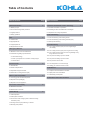
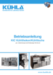
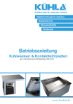
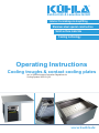
®
Kühltechnik & Ladenbau GmbH
Interior Furnishings & shopfitting
Stainless steel special construction
Solid surface materials
Cooling technology
Operating Instructions
Cooling troughs & contact cooling plates
acc. to German Accident Prevention Regulations for
Cooling Systems VBG 20 § 20
www.kuehla.de
We are very pleased to have the opportunity of
presenting our new KÜHLA cooling device to you
today. Our cooling troughs and contact cooling
plates are items for serving counters for drinks
and packaged food (classification 3M2).
Through purchasing this item of equipment, you
have selected a product which combines the
highest technical demands with practical ease of
operation. Therefore, we would like to ask you
to read the following pages carefully so that you
are able to quickly familiarise yourself with your
new cooling device. Please keep this operating
instruction manual in a safe place for future reference in case maintenance and repair work are
necessary.
The operating instructions only apply to our
ready-to-plug-in models and do not have any
relevance to our units without integrated cooling
technology.
For any further questions and service, please
contact our team by telephone or e-mail. We
would be glad to help.
We wish you a lot of enjoyment with your new
KÜHLA device.
Your Kühla-Team
This service is provided by:
KÜHLA Kühltechnik & Ladenbau GmbH
Nordkämpe 1 a
49377 Vechta-Langförden
Telephone: +49 4447 9633-0
Fax: +49 4447 9633-33
E-mail: [email protected]
Web: www.kuehla.de
®
Table of Contents
Table of Contents
1 General Information
Page
2
Table of Contents
8 Operation and Automatic Control Technology
1.1 Delivery scope
8.1 General Information on operation
1.2 Conventions and general provisions
8.2 Resetting of alarm and maintenance messages
1.3 Legal provisions
8.3 Adjustment of cooling temperature
1.4 Safety guidelines
9 Care and Cleaning
2 Use
2
9.2 Care and cleaning of the cooling machine (unit)
2.2 Appropriate use
9.3 Start-up after cleaning
2.3 Inappropriate use
10 Troubleshooting
2.4 Requirements for staff
10.1 The cooling machine (unit) is not running/Cooling is
not working
3
3.1 Behaviour in the event of malfunctions
7
7
10.2 The cooling machine (unit) is running but is not cooling
10.3 The cooling machine (unit) is not running although everything seems to be in order
3.2 Information regarding special hazards
3.2.1 Electrical energy
10.4 The panel is misting up on the outside
3.2.2 Lift up evaporator for convection cooling troughs
10.5 The panel is misting up on the inside
3.2.3 Noise level
10.6 The products are too cold
4 Technical Data
6
9.1 Care and cleaning of the cooling device
2.1 Intended use
3 Emergency Measures
Page
3
10.7 The refrigeration is not cold enough
4.1 Classification
10.8 Calling your customer service centre
8
4.2 Ambient temperatures
11 Maintenance
8
4.3 Adjustment range thermostat
11.1 Inspection and maintenance schedule
4.4 Performance cooling machine (unit)
11.2 Spare parts and consumables
5 Delivery and Transportation
4
12 Attachments and further information
5.1 Incoming goods and initial inspection
5.2 Disposal of the packaging
5.3 Disposal of the old appliance
6 Connection and Assembly
5
6.1 Electrical connection
6.2 Waste water connection
7 Initial Start-Up
7.1 Initial inspection
7.2 Initial system checkout
7.3 Connection of the cooling system to external cooling
machines (units)
7.4 Cooling machine (unit) switching on and off
7.5 Stocking with products
11.3 Dismantling and disposal
5
8
Operating instructions
Cooling troughs/Contact Cooling Plates
The following notices refer to our ready-to-plug-in (convection) cooling troughs and contact cooling plates from the series:
– Cooling troughs, piped and unpiped (fig. 1)
– Convection cooling troughs for baking trays, with lift up evaporator (fig. 2)
– Convection cooling troughs for containers according to the catering industry standard (Gastro-Norm), with lift up evaporator (fig. 3)
– Contact cooling plates, flat (fig. 4)
– Contact cooling plates, deep-drawn (fig. 5)
+++ Some cooling trough models, ready-to-plug-in, completely assembled
Fig. 1
+++ Some contact cooling plate models, ready-to-plug-in,
completely assembled, flat and deep-drawn
Fig. 4
Fig. 2
Fig. 5
Fig. 3
|1
®
1 General Information
1.1 Delivery scope
Our cooling troughs and contact cooling plates have been optimized to meet the requirements of our customers and are available in different designs. Please
note, therefore, that the description of components in the instructions does not necessarily apply to your particular model. Please refer to your order confirmation
or delivery note for a detailed summary of the scope of your delivery.
1.2 Conventions and general provisions
Please bear in mind ...
– the applicable laws, standards and regulations
– the country-specific regulations
– the state of the technology at the time of initial start-up
– the present operating instructions
–, that the technical design of the units may change without notice
–, that operating instructions only contain general provisions. Please observe these in the context of your system
1.3 Legal provisions
The operating instructions are an integral part of the equipment, guarantee and statutory warranty. It must be passed on to the user. Within the framework of the
statutory warranty, defects in electrical components due to faulty manufacture or material defects will be resolved free of charge within a period of six months.
Furthermore, KÜHLA products are guaranteed for two years. Defects in equipment which are based on faulty manufacture or material defects will be repaired
or exchanged free of charge within the two-year guarantee period.
Please note:
The guarantee or warranty is void if the product has been tampered with or misused in any way.
1.4 Safety guidelines
All generally applicable safety regulations were observed in the manufacture of your cooling equipment. Before leaving the factory your cooling device underwent a final inspection. During the process, all electrical parts were examined to ensure they were fully functional. The test report of in-production testing of
electrical appliances for household use and similar purposes according to EN 60335/VDE 0700 is enclosed with the cooling device. Please ensure that the
touch guard has been correctly installed in accordance with VDE regulations.
2 Use
2.1 Intended use
The cabinet is intended to be used as a serving counter for dispensing food and drink. Our cooling troughs and contact cooling plates are designed exclusively
for temporary storage and sale of pre-cooled products. They are not suitable for cooling down food products and beverages. Beverages or food products can
be stored only in the designated containers and storage compartments of the cooling device. Please avoid storing aggressive foodstuffs which contain acetic or
lactic acid or similar ingredients without the appropriate protective packaging. The cooling device should not be filled with food or beverages whose temperature
is higher than the default temperature (according to EN 441-11, part 4.1). The equipment is not designed to cool food items with closed-cell covering, (this includes e. g. chocolate, chocolate candies, marzipan), as the specific nature of the cooling system may cause these food products to “sweat”. Please make sure
you do not overload the equipment. This will impair its performance and proper functioning. Please only use the cooling device for the intended use indicated.
Please note:
Proper functioning of your cooling device is only guaranteed if assembly, installation and operation have been conducted
in accordance with the operating instruction manual.
2.2 Appropriate use
Appropriate use also includes reading and observing the assembly and operating instructions and compliance with the inspection and servicing conditions. The
cooling device is operationally safe in accordance with the state of the art applicable at the time of delivery and the recognized safety regulations. Nevertheless,
a danger to life and/or limb of the user or third parties and/or damage to the cooling device and other property may arise through its use, if improperly handled
by untrained personnel or if used for any other purpose than that for which it is intended.
Please note:
Please never use your cooling device for any other non-specified purpose!
In order to prevent risks to the user and to avoid damage to the device, the device may only be used when in perfect working order and by observing its intended
purpose as well as having due regard for aspects of safety and hazards! The cooling device is only intended to be used for the purposes listed in Section 2.1!
The manufacturer/supplier is not liable for any damage resulting from inappropriate use. The user bears the risk.
The cooling device is to be so fitted that it provides easy access for maintenance and repairs. Should dismantling of safety devices be necessary owing to
maintenance and repair work, please remember to check all the safety devices immediately following completion. Please always firmly tighten all loosened
screw connections after maintenance and repair work. Please dispose of exchange parts, working- and auxiliary materials safely and in an environmentallyfriendly manner.
Please note:
Modifications are only permitted by the manufacturer. Repairs may only be undertaken by a qualified professional or by our customer
service centre. Only original replacement parts may be used. If interventions or changes have been performed on the cooling device, then
warranty claims are void.
2
|
Operating instructions
Cooling troughs/Contact Cooling Plates
2.3. Inappropriate use
Safety, protection and control systems may not be adjusted or rendered ineffective. Please avoid any intervention with the cooling circuit and the cooling device.
Leak-detection and refilling of cooling fluid are only permitted by the manufacturer or the customer service centre. When refilling with cooling fluid, please only
use the cooling fluid indicated on the label. Ensure that the ventilation stack is not covered or blocked and that the condenser and the cooling machine’s (unit)
air vents are not covered, blocked or otherwise restricted in its transverse section.
2.4 Requirements for staff
– Do not expose the unit to extreme weather influences such as rain, direct sunlight etc.
– Please instruct everybody coming into contact with the cooling device on how it should be correctly handled
– Always pull the power plug out of the socket outlet directly via the plug and not via the cable
– Do not overload the cooling device. The cold must be able to circulate
– On a weekly basis, please remove dust and deposits from the cooling machine (unit) using a hand brush or vacuum cleaner to ensure that cooling capacity remains stable
– Ensure that the air intake areas and air outlet areas on the cooling machine (unit) are not blocked or covered
– Do not allow children to be unattended near the cooling device
– Please keep packaging materials (plastic bags, foil, styrofoam, nails, screws, wooden panels etc.) out of the reach of children
– Please beware that the evaporator is movable for cleaning the ground of a convection cooling trough
3 Emergency Measures
3.1 Behaviour in the event of malfunctions
Regardless of the instructions below, local safety regulations shall continue to apply for operation of the cooling device. In the event of a fault, please immediately switch the cooling device off and unplug the power plug or remove the fuse. The unit may only be put back into operation after the fault has been
successfully dealt with.
Please note: Electrical repairs may only be carried out by authorised professionals! Only original replacement parts which have been obtained
from the manufacturer may be used.
In the event of a fire, containers and systems filled with cooling fluid may violently explode. Cooling fluids themselves are not flammable, however, at high temperatures they can decompose into toxic products. In the event of a fire, please cool the containers and systems with a jet of water.
For your own safety use self-contained breathing apparatus.
3.2 Information regarding special hazards
3.2.1 Electrical energy
Please immediately turn the cooling device off if any disturbance to the supply of electric power occurs! Please note that work on electrical systems or electrical
controls may only be conducted according to the electrotechnical rules by a qualified electrician or instructed persons under the direction and supervision of
a qualified electrician. Appliances and components where inspection, maintenance and repair work is to be conducted must be disconnected from the power
supply and voltage-free. First check the disconnected parts are voltage-free, then earth and short-circuit. Please isolate the neighbouring live parts.
Please note: Electrical equipment is to be checked regularly. Defects such as loose connections or burnt wiring, must be corrected immediately on becoming aware of the issue. Only use voltage-isolated tools.
3.2.2. Lift up evaporator for convection cooling troughs
Please replace immediately if the gas-pressure springs, which keep the evaporator in the upright position during cleaning, lose strength and no longer hold the
evaporator securely in an upright position. Call Customer Service or commission an authorised expert to replace the gas-pressure springs.
3.2.3 Noise level
The workplace-related emission value of the sound level is less than 70 dB (A).
4 Technical Data
The values listed here correspond to the standard designs of equipment. They may vary according to modifications and type. Additionally check the details on
your order confirmation and on the unit label. Please also note that temperatures – as indicated – can be affected by external influences. These includes e. g.
lamps, cooking utensils, a glass top if used, or devices in close vicinity which generate heat. Lamps should be equipped with a cooling system if required. If a
glass top is used, then care should be taken that it is only open towards the service side and that it is not open towards the customer or at the sides.
4.1 Classification
3M2
4.2 Ambient temperatures
Optimized for an ambient temperature of +26 °C at 60 % rel. humidity
Maximum temperature machine room: +38 °C 4.3 Adjustment range thermostat
Default setting: +1 °C to +15 °C, factory setting: +3 °C to +5 °C
|3
®
4.4 Performance cooling machine (unit)
Model-Name
Cooling unit
Danfoss
R134a
Supply voltage
cooling machine (unit)
(volt/hertz)
Cooling performance
cooling machine (unit)
(watt)
at VT -10 °C
Power consumption
cooling machine (unit)
(watt)
at VT -10 °C
Cooling load
(watt)
at VT -10 °C
Convections models
Convection cooling trough, GN 2/1*
Typ FR 8,5 GX T0
230 V/50 Hz
372 Watt
305 Watt
370 Watt
Convection cooling trough, GN 3/1*
Typ SC 10 GX T0
230 V/50 Hz
451 Watt
335 Watt
450 Watt
Convection cooling trough, GN 4/1*
Typ SC 12 GX T0
230 V/50 Hz
605 Watt
440 Watt
610 Watt
Convection cooling trough, GN 5/1*
Typ SC 18 GX T2
230 V/50 Hz
825 Watt
560 Watt
820 Watt
Convection cooling trough for 2 baking trays
Typ FR 10 GX T0
230 V/50 Hz
451 Watt
335 Watt
450 Watt
Convection cooling trough for 3 baking trays
Typ SC 12 GX T0
230 V/50 Hz
605 Watt
440 Watt
600 Watt
Convection cooling trough for 4 baking trays
Typ SC 18 GX T2
230 V/50 Hz
825 Watt
560 Watt
820 Watt
Cooling trough, piped, GN 1/1*
Typ TLS 5 FX NO
230 V/50 Hz
215 Watt
225 Watt
150 Watt
Cooling trough, piped, GN 2/1*
Typ TLS 5 FX NO
230 V/50 Hz
215 Watt
225 Watt
200 Watt
Cooling trough, piped, GN 3/1*
Typ FR 8,5 GX NO
230 V/50 Hz
372 Watt
325 Watt
250 Watt
Cooling trough, piped, GN 4/1*
Typ FR 8,5 GX NO
230 V/50 Hz
372 Watt
325 Watt
300 Watt
Cooling trough, piped, GN 5/1*
Typ SC 10 GX NO
230 V/50 Hz
451 Watt
350 Watt
350 Watt
Contact cooling plate, deep-drawn, GN 1/1*
Typ TLS 5 FX NO
230 V/50 Hz
215 Watt
225 Watt
70 Watt
Contact cooling plate, deep-drawn, GN 2/1*
Typ TLS 5 FX NO
230 V/50 Hz
215 Watt
225 Watt
130 Watt
Contact cooling plate, deep-drawn, GN 3/1*
Typ TLS 5 FX NO
230 V/50 Hz
215 Watt
225 Watt
190 Watt
Contact cooling plate, deep-drawn, GN 4/1*
Typ FR 8,5 GX NO
230 V/50 Hz
372 Watt
325 Watt
240 Watt
Contact cooling plate, flat, GN 1/1*
Typ TLS 5 FX NO
230 V/50 Hz
215 Watt
225 Watt
70 Watt
Contact cooling plate, flat, GN 2/1*
Typ TLS 5 FX NO
230 V/50 Hz
215 Watt
225 Watt
130 Watt
Contact cooling plate, flat, GN 3/1*
Typ TLS 5 FX NO
230 V/50 Hz
215 Watt
225 Watt
190 Watt
Contact cooling plate, flat, GN 4/1*
Typ FR 8,5 GX NO
230 V/50 Hz
372 Watt
325 Watt
240 Watt
Models, piped
* Gastro-Norm standard-container, according to the catering industry standard
5 Delivery and Transportation
5.1 Incoming goods and initial inspection
Please examine your cooling device immediately upon arrival for any damage caused during transit. Failure to notify any damage caused during transit in a
timely or proper manner will result in loss of entitlement to settlement! Should any damage be determined, this is to be confirmed by the carrier. Please unpack
and inspect the delivery item immediately upon receipt and determine its condition and operability. In the event of damage, please notify either us or your
supplier regarding the nature and extent of the defect. Our claims department is responsible for notifying the insurance company regarding cooling devices
delivered by us.
Please note:
Do not assemble cooling devices with obvious defects. In such an event you will lose any claims to your guarantee and warranty.
5.2 Disposal of the packaging
All cooling devices are covered by a protective film of polyethylene to protect the surfaces during despatch. Please remove this film immediately upon receipt
as the film hardens when exposed to sunlight making removal difficult. Please return all recyclable packaging material to the usual local recycling collection
centre so that it can be forwarded for reprocessing.
5.3 Disposal of the old appliance
Please make the old units inoperable before scrapping by cutting through the power cable. Please observe the valid regulations for environmentally-friendly
and proper disposal.
4
|
Operating instructions
Cooling troughs/Contact Cooling Plates
6. Connection and Assembly
The cooling device should be set up and connected by a professionally qualified fitter.
The mounting situation at the point of installation must be in compliance with the general conditions as per EN 441-11, i. e. please ensure that your cooling
device is installed on a solid, dry ground. Extreme weather conditions, e. g. direct sunlight and unnecessary radiant heat, caused for instance by lamps, ovens,
heaters etc. should be avoided. The minimum distance from walls and other surfaces should be at least 100 mm. Select a well-ventilated, dustfree room. Please
ensure in particular that your equipment is in a horizontal position so that the cooling fluid in the device is evenly distributed. Avoid draughts in the immediate
vicinity of the convection area.
6.1 Electrical connection
Before connecting the cabinet, please ensure that the details on the cooling machine (unit) comply with the values from the in-house installation. Safety regulations must be adhered to under all circumstances.
Observe electrical safety. This is only guaranteed if the cooling appliance is properly installed and grounded according to the general provisions of the VDE. In
case the socket outlet does not match the plug with earthing contact, the socket outlet should be replaced with one that is suitable. If necessary, please consult
a qualified expert who will check your in-house installations.
The cooling device is delivered ready-to-plug-in with a connecting lead approximately 1.5 metres long. For operation, please only connect the device using a
plug with earthing contact to an AC mains power supply with a nominal voltage of 230 V and a frequency of 50 Hz. In devices with a power input of less than
2 KW, the electrical supply must be fused with 10 A (time-delayed), in devices with a higher power input with 16 A (time-delayed). It is not permitted to use the
connection with any other voltage, type of current or frequency. Installation of the plug with earthing contact is to be carried out by an electronics expert. National
regulations must be observed.
6.2 Waste water connection
All piped troughs and all convection cooling troughs require a waste water connection. Please consult a qualified professional for installing the waste water
connection.
7 Initial Start-Up
The following notices refer to our ready-to-plug-in cooling devices. If another company’s cooling machine (unit) and control mechanism are installed, please
proceed according to their operating instructions.
7.1 Initial inspection
Inspect the cooling device before initial start-up. Defective units must not be put into operation! When installing ready-to-plug-in cooling devices it is essential
to ensure that the heat generated by the cooling machine (unit) can easily dissipate. Poor heat dissipation, especially at higher ambient temperatures, can
lead to the cooling capacity of the unit being greatly reduced. If heat accumulation is allowed to build-up, this can even lead to the cooling machine (unit) being
damaged.
Please note:
The cooling device is optimised for an ambient temperature of +26°C at a relative humidity of approximately 60 %.
Under no circumstances may the ambient temperature directly at the mechanical cooling machine (unit) exceed +38 °C for longer periods!
(See also Section 4.2)
7.2 Initial system checkout
Before initial start-up, allow a two hour period to pass between installing the cooling device and starting the machine. This settling period is necessary so that
the oil, which may have shifted during transit, can return back into the machine. Remove all protective film and clean the cooling device before initial start-up.
7.3 Connection of the cooling system to external cooling machines (units)
Our cooling units are supplied with pre-installed expansion valves and with outgoing copper pipes. By default, we use an expansion valve for the cooling fluid
R134a. If explicitly requested we can also install other expansion valves. Please check before installation of the cooling system, whether the correct expansion
valve for your cooling device has been fitted.
The evaporator in this device was subjected to a leakage test during production at our site. Before connecting the evaporator, please conduct an additional
leakage test in order to ensure that there are no leakages. For this purpose, we have already pre-filled the evaporator with nitrogen. When opening the cooling
pipes, please check whether the test pressure is still adequate. If there is no test pressure, it is fair to assume that a leak developed during transportation or at
the time of handling. In this case do not install the device, but send it back for replacement after consultation with us.
|5
Please note:
For special designs, see the order confirmation for the cooling capacity required. In the event that longer copper pipes are intended to be
placed between the cabinet and cooling machine (unit), the loss of refrigeration should be correspondingly taken into consideration.
Please note:
We typically use R134a cooling fluid.
®
7.4 Cooling machine (unit) switching on and off
If the cooling device is in order, please press the On-/Off-switch
vary depending upon the features of the model.
.This is usually located directly on the thermostat, however the position of the switch may
Depending on your own operational requirements, you can leave your cooling device to run continuously. Regularly pre-set control and maintenance intervals
guarantee the operation is reliably monitored. If desired, you can also turn off your cooling device if there is no need to keep products cool for several hours. To
do this, simply press the On-/Off-switch
or unplug the power cord.
7.5 Stocking with products
Before stocking the cooling device with chilled goods, please wait until the desired temperature has been reached. Never overfill with products.
8 Operation and Automatic Control Technology
The cooling system has been installed and adjusted by an expert at the factory. Please only allow specially trained personnel to service and repair your cooling
device. Largely restrict your activities to adjusting the temperature on the thermostats, stocking with products, defrosting and cleaning the cooling device. We
recommend contracting a local refrigeration company to service your machines.
8.1 General Information on operation
The regulator for your cooling device has a pre-installed factory setting that ensures optimal operation. The cooling device automatically reports when it is
due for maintenance or when a service outside of normal operation is required. The abbreviations shown in the display provide information on the respective
circumstance. For information regarding the meaning of each abbreviation, please see Table 1 in the grey box below (Page 6). During normal mode, the display
shows the current cold room temperature (actual value).
In order to enter the menu, briefly press the button with the symbol
and immediately release again. By repressing the button
you can scroll through the
menu and view the different pre-set data, please see Table 2 in the grey box below (Page 6). To exit the menu and return to the current cold room temperature
display, press the button with the symbol or wait for 30 seconds. The thermostat will then automatically reset.
8.2 Resetting of alarm and maintenance messages
Resetting the display (RESET): At regular intervals, the regulator shows pending maintenance and service intervals. These are also accompanied by an ausymbol. The
dible signal. In order to reset the display, please select the corresponding menu item (please see Description 8.1) using the button with the
interval values can be displayed using the button with the symbol. If the value is indicated on the display, keep pressing the button with the symbol whilst
simultaneously pressing the button with the symbol. The value will be reset. If no further buttons on the display are pressed, after a short while the cold room
temperature display (actual value) will reappear on the display. The pre-set maintenance and service intervals are not affected by a RESET process.
8.3 Adjustment of cooling temperature
By default, the cooling temperature lies+ between 3 °C and 5 °C. The temperature sensor is located at the hottest point in the recirculating air, i. e. as a general
rule, all products are colder than the temperature displayed.
If you wish to change the pre-set cold room temperature, then proceed as follows: Press the button with the symbol for half a second, in order to display the
setpoint value. Once the target value is displayed, keep pressing the button with the symbol and adjust the value using the button or the button until
the desired value has been reached. Once the button with the symbol is released, the new value is stored. The adjustment setting can take place within the
pre-set temperature limits which lie between the minimum value of +1 °C and the maximum value of +15 °C. Please do not go below or exceed these values.
For further information, please read the enclosed detailed instructions on the related LAE thermostat (Company Berndt Contec; LAE Electronic).
Table 1 Display Normal operation:
In normal operation, the display shows the actual temperature or one of the following abbreviations:
Defrost in progress
Electronics in STAND-BY mode
Condenser clean warning
“Door Open” alarm
Condenser high temperature alarm
Cold room high temperature alarm
UP button/ MANUAL CONTROL button
Cold room low temperature alarm
Generic alarm
Manual defrost button/
DOWN button
EXIT button/
STANDBY button
Probe T2 failure
*
Probe T3 failure
Table 2 Info Menu Available Data:
Alarm
INFO button/
SETPOINT button
Probe T1 failure
*
Cooling/heating output
Instant probe 1 temperature
*
Instant probe 2 temperature
*
Instant probe 3 temperature
Maximum probe 1 temperature recorded
Auxiliary output
Minimum probe 1 temperature recorded
Compressor working weeks
Keypad state lock
* Display will only appear if multiple probes are connected
6
|
Operating instructions
Cooling troughs/Contact Cooling Plates
9 Care and Cleaning
9.1 Care and cleaning of the cooling unit
The cooling system should be cleaned once a week. Approximately one hour before cleaning is due to commence, switch off the system by pressing the
button on the thermostat. You may also disconnect by unplugging the plug with earthing contact. Leave the cooling device to defrost until the evaporation system is free of ice. Never remove ice build-up on the evaporation system using sharp-edged objects in order to avoid damage. Check the condensate drain or
condensate trough (if extant). Remove dirt and waste remnants from the products and clean the cooling section with a damp cloth. Please use lukewarm water
with a dash of washing-up liquid added. Please refrain from using cleaning agents that contain abrasive agents in order to protect the surfaces.
9.2 Care and cleaning of the cooling machine (unit)
In order for each of the air-cooled cooling machines (unit) to operate trouble-free, ensure supply and discharge of fresh air is unhindered. Please ensure that
during operation fresh air is able to flow freely directly in front of the condenser and the exhaust air is able to discharge above the machine. Any obstruction to
the air flow from the fan leads to an overloading of the cooling machine (unit) and can thereby lead to the motors burning out.
Regularly remove dirt from the condenser by suction cleaning with a vacuum cleaner. Dried on encrustations and fat residue should be removed at least every
three months using a degreasing agent because dust and dirt particles which are attracted by the ventilator and drawn through the condenser form a dust carpet
in front of the fin system and impair the performance of the machine.
9.3 Start-up after cleaning
After cleaning, examine the cooling device to ensure that no connections have come loose or damage caused. In the event of a defect or fault, please call in
and, if necessary, replace the main power socket after cleaning to
suitably qualified and competent specialists to deal with it. Press the On-/Off-switch
restart the machine.
Please note:
We can assume no liability for damage caused by failure to comply with these care and cleaning instructions.
10 Troubleshooting
If you notice any system malfunction on your cooling unit, first check whether any of the following examples apply and inform the customer service centre. In
the event of a system malfunction, please immediately disconnect the unit from the power system.
10.1 The cooling machine (unit) is not running/Cooling is not working
– Check whether the On-/Off-switch
for the thermostat has been switched on
– Check whether voltage is present and whether the safety plug sits firmly into the socket outlet
– Check the fuses in the fuse box
– If the fail-safe circuit of the switch cabinet or the protective switch gear trips again, then there is a defect in the electrical installation or
the cooling machine
In such an event, please call a local electrician for his expert opinion. This may help in most cases. Only contact the customer service centre if the electrician
has determined a defect with the cooling machine (unit).
10.2 The cooling machine (unit) is running but is not cooling
– Please check the temperature in the machine room. It should not exceed +38 °C. Supply air should be able to circulate freely
– Remove any possible dirt on the ventilation grilles of the cooling machine (unit)
– Check whether evaporator fins in the cool room are covered in ice. Large amounts of ice prevent sufficient refrigeration (immediately defrost)
– Please determine the cause of this (condensate cannot drain freely, cooling room doors do not seal properly, thermostat has been adjusted etc.)
– Check whether the fans on the evaporator in the cool room are functioning
– Please check the sight glass above the cooling machine. If the sight glass has coloured yellow or air bubbles are visible, either cooling
gas is absent or moisture is in the cooling circuit. Please immediately call the customer service centre
10.3 The cooling machine (unit) is not running although everything seems to be in order
– Check whether the machine is in the process of defrosting (see control light on the thermostat)
– Check the temperature in the outer area of the cooling section or in the cooling room! It is possible that the temperature is so low that the thermostat is
not responding
– If you have carefully examined all the options with no success, please immediately notify the customer service centre
10.4 The panel is misting up on the outside
– Please check if the temperature has been set too cold
– Check whether steam-generating appliances are in the vicinity
– Test to see whether the relative room humidity is higher than 60–70 %
– Please check whether the thermostat is correctly calibrated
– Please check that the minimum distance of 100 mm from walls and other surfaces is maintained
10.5 The panel is misting up on the inside
– Verify that doors or flaps have not been open too long
– Check whether the defrosting time is taking too long
|7
®
10.6 The products are too cold
– Verify that the thermostat is correctly calibrated
– Check if the temperature has been set too cold
– Check whether you have read the instructions for stocking with products attentively (Section 7.5) and followed these correctly
10.7 The refrigeration is not cold enough
– Check whether the condenser has been cleaned
– Check the ambient temperature. It is possible that this is too high
– Check whether you have stocked your cooling device with too many or too warm foods
– Check whether you have read the instructions for stocking with products attentively (Section 7.5) and followed these correctly
– Check whether the evaporator is in the process of defrosting
– Check whether the cooling machine (unit) is sufficiently ventilated on the operator's and the customer's sides
– Verify that the thermostat is correctly calibrated
10.8 Calling your customer service centre
If you are ringing your customer service centre to report a fault, please state your exact and complete address along with your telephone and/or fax number
to the person in charge. Please give the name of the sales vendor to the customer service centre and inform him which cooling device it concerns. Describe
in detail how the fault manifests itself and provide the customer service centre with a brief summary of what steps you have already undertaken yourself. The
customer service centre will best be able to help you with this information.
For further questions please contact your sales vendor.
11 Maintenance
11.1 Inspection and maintenance schedule
The maintenance intervals are pre-set. For all further information please refer to the enclosed operating instructions of Berndt Contec/LAE Electronic.
11.2 Spare parts and consumables
Please contact your respective sales vendor for details when required.
11.3 Dismantling and disposal
First disconnect the cooling device from the power system. Please make the old unit inoperable before scrapping by additionally cutting through the power
cable. Also ensure that the cooling fluid in the device has been properly pumped out and disposed of by an authorised dealer.
Please observe the valid regulations for environmentally-friendly and proper disposal as a basic principle.
12 Attachments and further information
Depending upon your requirements and particular cooling device, there may be further enclosures attached to these operating instructions, these may include: further instructions, general drawings, detail drawings, exploded assembly drawings, documentation etc. Please store all documents in a safe place.
Thank you very much!
8
|