1
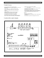
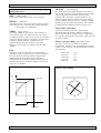
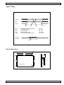
Operating Instructions
5-Phase Stepping Motor Drive
smd553
Revision:
44/99
BAUR Drives and Controls
1
Documentation: smd553
Product Features
- For all common 5-Phase stepping motors
- Powerful power drive: bipolar, chopped, low noise and
little losses
- Very compact size: L:W:H (125:100:35) mm
- Only one operating voltage of 21 Volt to 40 Volt
required
- Motor current setting with scaled potentiometer
(1,0 to 2,5) A
- 4000, 2000, 1000, and 500 steps/revolution
- Automatic current reduction can be enabled
- Active ballast circuit against over voltage
- Integrated fan control at over temperature
- All connection with robust screw terminal technology
- Inputs: Pulse, Direction, Fast Run, Gate/Off, Reset,
Location of the control elements
BAUR Drives and Controls
2
- Outputs: Zero position (Index), Ready,
Fan control
- All signals are galvanically isolated with opto couplers
- Step frequency up to 100 kHz
- LED-display for Power, Ready, Zero position,
Over-temperature, Ballast circuit, Current reduction
- Protection against Over-temperature, Over-current and
Voltage surge (integrated active ballast circuit)
Options:
- 5V or 24V signal interface
- Function Gate(Gate) or Off(Power drive off) selectable
via jumpers
- Fan module for operation with high motor current
Documentation: smd553
Wring Diagram
Function Description
FR:
GDR: (GATE, POWER DRIVE_OFF, RESET)
The function of the input GDR depends on the jumper
setting „OFF“ or „GATE“.
A lower step resolution is selected if the input is activated.
The effect is that the right jumper setting becomes active:
The has the following effect on the step rate:
- 4000 -> 1000
- 2000 -> 500
- 1000/500 -> no effect
Function GATE: (Jumper set to „GATE“)
All pulses are ignored by the power drive is the input GDR
is active. With this function it is possible to operate
multiple power drive with one pulse source.
Function POWER DRIVE_OFF: (Jumper set to „OFF“)
The active signal switches off the motor current, so that the
motor shaft can be easily manually moved. However, the
internal step counter is not deleted with this function.
Function RESET: (Always active)
Switches from the error condition to the operating
condition
BAUR Drives and Controls
3
(Fast Run)
!Attention:
Switching is only possible without offset in the so-called
zero position. This zero position is automatically set at
power drive on and is indicated via LED and output.
PULSE:
With a positive signal a step is moved. The power drive
reacts only on signal edges. With active current reduction
(Jumper „current reduction“ inserted) and pulse
interruptions for more than approx. 100ms, the motor
current is reduced to approx. 60% of the set value.
Documentation: smd553
The current reduction does not work if the pulse signal
remains static active.
DIR:
(DIRECTION)
The direction signal sets the motor sense of rotation.
READY: (Readiness)
This output is active when power drive operates error free.
The following errors switch the output to high impedance:
Over-voltage, Over-temperature
ZERO:
(Zero position)
The output „ZERO“ or zero position can be used for an
exact reference point. This output becomes active in the
so-called zero position, which is set at power-on and which
is always a half step position. The output is switched active
as follows: 4000/80, 2000/40, 1000/20 500/10, on
condition that the movement is always in the same
direction. The zero position is indicated with the LED
„ZERO“.
FAN:
The output „FAN“ becomes active at a heat sink temperature over approx. 60 Grad. This is to be interpreted as
an over-temperature warning. With this output the fan
module (available as an option) can be controlled
automatically. The condition is indicated with an LED. If
the heat sink temperature exceeds 70 degrees Celsius, the
power drive is disabled.
UB,GND:
(Power Supply)
The power drive can be operated within a range of 21 to
max. 40 Volt. It must be guaranteed that the power supply
output voltage does not exceed 40 Volt at no-load
operation and +10% mains voltage and that there is a
sufficient charge capacitor connected of at least 6800yF.
An active ballast circuit prevents over-voltages caused by
generator operation at rapid decelerations. This condition
is indicated with an LED that must only shortly be lit.
Motor cable connection
Under no circumstances the motor cable must be
disconnected during operation. Induction voltages can
destroy the power drive. For this reason it is important to
have a good connection between the motor cable wires and
the screw terminals.
Motors current setting: (approximate values)
The motor current can very easily be set with the
potentiometer. Generally it can be said that only as much
current is set as necessary. The following table of settings
can be helpful.
Fully CCW
9 O’clock
12 O’clock
3 O’clock
Fully CW
1,0 A
1,2 A
1,5 A
2,0 A
2,5 A
Motor current setting
T[°C]
12
70
60
9
Fan
Drive disabled
BAUR Drives and Controls
4
3
Documentation: smd553
The set motor current will be reduced at higher step
frequencies because of the motor inductance. The result is
a reduction of the motor torque (see motor specifications
of the motor manufacturer). A high current motor version
with low impedance is recommend.
Automatic current reduction
The automatic current reduction is activate by setting the
jumper „CURRENT REDUCTION“. The motor current is
reduced to approx. 60% of the set motor current.
The power dissipation of the motor and the power supply
is reduced significantly.
The current reduction is activated if the pulse input is
inactive for more than 100ms.
Current reduction
Pulse
Reduction
At pulse frequencies of less than 10 Hz it is possible that
the current reduction is very shortly activated. To avoid
this, the start/stop-frequency should be step much higher
than this 10 Hz.
The current reduction can be blocked if the pulse input
remains at static high signal level.
Immediately after an active pulse input the nominal current
is set again
BAUR Drives and Controls
5
Error mode
The readiness signal will be switched off. The motor is
switched off. The ready LED is switched off. The error
condition is memorized and can only be reset by activating
the inputs „GDR“. The error mode is initiated if the
temperature exceeds approx. 70°C
Documentation: smd553
Signal Timing
PULSE
DIR
GDIS
tprvt
tprvt:
tpvr:
tpnr:
tprnt:
tpab:
tpvr
tpnr
PULSE/DIR before active GDIS
PULSE before DIR
PULS after DIR
PULS/DIR after GDIS
Current reduction after PULSE
tprnt
min. 5ys
min. 10ys
min. 10ys
min. 50ms
max. 100ms
PULSE
Reduction
tpab:
Board Dimensions
125
32
117
91,5
100
alle holes 3,5mm
BAUR Drives and Controls
6
Documentation: smd553
Technical Data:
Trouble Shooting:
Module supply:
Absolute max. supply voltage:
Min. supply voltage
Recommended supply voltage:
Active ballast circuit:
Supply voltage ripple:
Input current at 35V/Im =max
Starting current:
Fuse:
Charge capacitor:
Supply cable wire cross section:
Distance to the charge capacitor:
42 V max.
21 V
38 V
> 46V
2 Vss max.
1,5 A max.
<3,0 A
4,0 A mt
10000 yF
0,75 mm²
1,0m max.
Motor connection:
Cable cross section:
Cable length:
0,75 mm²
10 m max
Motor has no holding torque moment, although voltage
is connected
Motor voltage is below the min. value
Power drive is switched off via the input „GDR/OFF“
Over-temperature shut off is still active
Motor generated holding torque but does not execute
steps
Input „GDR/GATE“ is active
Pulse level is too low (24V interface)
„TEMP“-LED is lit immediately after power-on
The heat sink was not able to cool down sufficiently
Sudden crackling noises in the motor
The motor is operated at the low voltage limit
Bad contact of the motor connection
Signal input interface:
5V (24V optional)
Input type:
Opto coupler, reverse polarity proof
Input voltage:
min.
4 V (21V)
max.
6 V (28V)
nominal
5 V (24V)
Input current
15 mA (10mA)
Pulse width:
min.
5ys
Pulse rise time:
max.
10ys
The motor starts but does not reach the end velocity
The motor voltage is too low for the required speed
Motor current set too low
Acceleration ramp set too high
Motor wires too long and/or too thin
Power drive is under dimensioned and voltage drop is too
high
Motor looses steps and drifts
Control signal amplitudes are too low
Control signal rise times are too high
Noise on signal wire is too high (Shielding ?)
Wiring concept is not optimal (all ground signals must be
wired in a star configuration to a common ground
potential)
Mechanical shaft coupling slips
Signal output interface:
Output type:
Opto coupler, reverse polarity proof
Switching voltage:
min.
3V
max.
30 V
Switching current:
max.
50 mA
Output resistance:
220 Ohm
Load:
only ohmic
Motor current setting:
Potentiometer CCW position:
1,0 A
CW position:
2,5 A
linear in between
! Forced air cooling is necessary for motor currents
higher than 1,5 A
Temperature monitoring:
Warning, Output „Fan on“:
Shut off:
The motor vibrates at pulse frequency but does not
start
Start/Stop-Frequency too high
Motor windings wrongly connected or broken cable
Automatic current reduction remains active (to little pulse
duration at low pulse frequencies)
Motor current set too low
60 °
Automatic current reduction does not work
Pulse input remains active after the last pulse
Jumper is not set
70 °
Current reduction active at pulse frequency:
Pulse width:
5ys
10ys
50ys
100ys
Current reduction.:50Hz 30Hz 20Hz 15Hz
Ambient conditions:
Temperature:
UL94V-1 all components
IP00
BAUR Drives and Controls
Over-voltage LED is lit often/continuously
! The supply voltage is too high
The motor gets very hot
Up to 85 degrees Celsius should be no problem
40° max
7