1
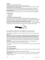
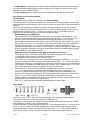
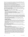
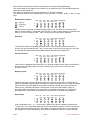
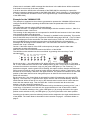
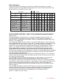
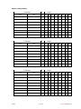
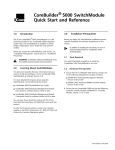
Operating Instructions for the EES MCS8
Table of Contents
General. ............................................................................................................. 2
Scope of Delivery. .............................................................................................. 2
Connections and Operating Conditions. ............................................................. 2
Operating the MCS8. ........................................................................................ 2
The four Operating Modes.................................................................................. 2
Description of the Operating Modes. .................................................................. 3
Standard Mode. ............................................................................................. 3
Manual Operation and MIDI Test.............................................................. 3
Matrix Overview ( Assignment of the MIDI commands to the outputs ). ... 3
Learn Mode.................................................................................................... 3
Running-Learn.......................................................................................... 4
Inverse-Learn. .......................................................................................... 4
Learn Mode - MIDI Channel. .................................................................... 4
Example for a Learn Session. .................................................................. 4
Matrix Mode. .................................................................................................. 5
Assignment: Outputs to a specific command pair..................................... 5
Assignment: Commands to a specific output............................................ 5
Special Mode. ................................................................................................ 5
Bank Select Function................................................................................ 6
Soft-Thru. ................................................................................................. 6
Instruction Filter. ....................................................................................... 6
Running-Learn.......................................................................................... 6
Send Dump. ............................................................................................. 6
Default On. ............................................................................................... 7
Inverse...................................................................................................... 7
How to leave the Special Mode. ............................................................... 7
Standard Tables and Initialization................................................................... 7
Standard Tables................................................................................................ 8
Bank 1 YAMAHA 02R Fader 1, 3, 5, 7 - 15 ....................................................... 8
Notes to the 02R............................................................................................ 8
Bank 2 YAMAHA DMC1000 Fader 1 to 8 .......................................................... 8
Notes to the DMC1000. ................................................................................. 8
Example for the YAMAHA O3D........................................................................ 9
Tips for using Yamaha O2R96....................................................................... 10
Tips for using Yamaha 01v96. ....................................................................... 10
Matrix Managing. ............................................................................................ 11
Matrix ( empty-tables )...................................................................................... 12
Troubleshooting. ............................................................................................ 13
System Exclusive Data Format. .................................................................... 13
EG-Konformitätserklärung - Declaration of Conformity............................. 14
Hard- and softwaredesign of the MCS8 are property of EES Technik für Musik, Mölln, Germany.
All trademarks referred in this instruction belong to their respective owners.
MCS8
Page 1
Op.Instr. Version 1.51
General.
Thank you for purchasing the EES MCS8.
The MCS8 is able to control 8 relay contacts by MIDI messages.
The Matrix Mode enables to switch 1 relay contact with different MIDI commands or different
relay contacts with only 1 MIDI command.
The MCS8 is able to learn different MIDI messages which are storeable in two bank sets.
So it is possible to start and stop for example a connected CD-player by moving a fader.
With the MIDI channel switch the basic MIDI channel can be selected so that several MCS8
can be daisy chained.
Ex works there are two default settings that fit to the YAMAHA mixers 02R and DMC1000.
Scope of Delivery.
• 1 EES MCS8.
• 1 power cable.
• 1 instruction.
Connections and Operating Conditions.
The MIDI Out of the controlling device ( for example the MIDI Out of the 02R ) must be
connected with the MIDI In of the MCS8. At the MIDI Thru of the MCS8 the signal is present to
feed other MIDI devices. The MIDI Out of the MCS8 needs to be connected only if the MIDI
commands of the MCS8 are supposed to be checked or to be stored.
The eight 1/4" stereo jack plugs are wired each with a relay contact: the contact is arranged
between top and ring, the shield ( ground ) can be used - if necessary - as a shield. All contacts
are independent of each other, there are no interconnections between the phone jacks.
Relay
Contact
NC / shield
If the switchchannel is switched Off ( red LED lights up ) the contact is opened.
If the switchchannel is switched On ( green LED lights up ) the contact is closed.
The MCS8 must be supplied with an ac line voltage of 230V / 50Hz by use of the enclosed
power cable.
!Make sure that the main-voltage matches the voltage printed on the backside: 230V∼!
The power consumption is very small. For a troublefree operation of your MIDI devices you
should limit your cables to a total lenght of 3 meters. During the operation of the MCS8 you
have to ensure proper operation conditions and the precautions usual for electronic devices:
Do not operate the device in moist environment, with high temperatures or in extremely dusty
environment. The case may be opened only by technical experts. There are no serviceable
parts inside.
In rare cases static discharge may disturb the EES MCS8. You can reestablish correct
operation by switching the power of the MCS8 of and on again.
For cleaning only use a dry cloth, solvent-containing cleaners can damage the lettered surface
of the device.
Operating the MCS8.
The four Operating Modes.
In the Standard Mode one LED lights up in every switchchannel, therefore 8 LEDs are always
active.
In the Learn Mode one or both LEDs of a switchchannel light up.
The yellow Learn LED lights up when Running-Learn is activated. It starts flashing if valid MIDI
messages arrive.
The yellow Learn LED lights up with every start of the Single Learn until the first valid MIDI
message is received.
MCS8
Page 2
Op.Instr. Version 1.51
The Matrix Mode is displayed by the slow and short flashing yellow Learn LED. According to
the selected kind of Matrix Mode one LED is flashing in the upper or lower line while in the
opposite line up to 8 LEDs can be lit.
The Special Mode attracts attention by its four flashing LEDs S7 and S8 / On and Off.
Description of the Operating Modes.
Standard Mode.
After switching on the MCS8, it is always in the Standard Mode.
The LEDs on the front panel are showing the current state of the relay contacts. A lit red LED
shows that this contact is opened. If the contact is closed, the green LED of this switchchannel
lights up.
The relays can be switched by MIDI according to the MIDI messages stored in the MCS8.
If one or more relay contacts are defined invers, the relevant LEDs are flashing fast ( look at
Special Mode, Inverse on page 7 ). After any key action or when a valid MIDI event for
switching or a valid MIDI dump was received, the flashing stops.
Manual Operation and MIDI Test.
The 8 relays can also be switched manually by the cursor keys on the front panel of the
MCS8. First the switchchannel must be selected by pressing the ← or → cursor key. Now
the active LED of the selected switchchannel is blinking. By pressing the ↑ key the
switchchannel will be switched On, now the green LED is blinking. If the channel is in the onstate during pressing the ↑ key the MIDI event to switch this channel on will be transmitted.
Pressing the cursor keys ↑ or ↓ while the switchchannel is already switched on or off,
transmits the MIDI data, used for this event to happen, as a test to the MIDI Out. Depending
on the assignment of the MIDI commands to the switch outputs ( see Matrix Mode on page
5 ) this could be up to 8 MIDI messages.
Matrix Overview ( Assignment of the MIDI commands to the outputs ).
There are two ways to show the assignment of the MIDI messages to the outputs.
1.) Assignment of the outputs to a specific command pair.
2.) Assignment of the commands to a specific output.
If the cursor key ↓ is pressed and held, by additional pressing the cursor keys ← or → the
first kind of assignment will be displayed. By further pressing the ← or → cursor key without
releasing the cursor key ↓ the assignment of the outputs to the former or next command pair
will be shown. The flashing red LED displays the number of the command pair ( 1 to 8 ), the
green LEDs show which outputs are assigned to this command pair.
If the cursor key ↑ is pressed and held down, by additional pressing the cursor key
← or →, the second kind of assignment will be displayed. By further pressing the ← or →
cursor key, without releasing the cursor key ↑ the assignment of the commands to the
former or next output will be displayed. The flashing green LED displays the number of the
output ( 1 to 8 ), the red LEDs show which commands are assigned to this output.
While the Matrix is displayed the MCS8 keeps on operating normally, only the LEDs are not
displaying the current state of the relay contacts.
If the ↓ or ↑ cursor keys are released the Standard Mode is active again.
Learn Mode.
Bank
Soft
Thru
Instr.
Filter
Run.- Send Default Spezial Mode
Learn Dump On
+
3 5 4
9
1
15
11
13
On
Off
S1
(
S2
S3
= LED off,
S4
S5
S6
S7
S8
Learn
+
Channel
= LED on )
If the cursor keys ↑ and ↓ are pressed simultaneously, the Learn Mode will be started.
The first pair of LEDs ( S1 ) and the yellow Learn LED light up.
This Mode is used to teach in new MIDI events for switching the relays.The teach in must be
done separately for each of the 8 command pairs.
All MIDI controllers, Programchange and Note-On / -Off commands ( Bx cc vv, Cx pp, 8x nn vv,
9x nn vv ) can be used by the MCS8. Additional the system-exclusive data (SysEx) of the
YAMAHA 02R faders will be recognized. By the cursor keys ← or →, the desired command
place can be selected. During the selection both LEDs of the selected place light up.
MCS8
Page 3
Op.Instr. Version 1.51
By the cursor key ↑ the Learn Mode can be entered, only the green LED still lights up. If the
cursor key ↑ is pressed again, the green LED flashes. The switchchannel will be switched on
with all values, equal or higher than the teached in value.
By the cursor key ↓ the Learn Mode for switching off the contact is entered, only the red LED
still lights up. If the cursor key ↓ is pressed again, the red LED flashes. The switchchannel will
be switched off with all values equal or lower than the teached in value.
The higher or lower option can be switched off by pressing the cursor key again. This selection
can be changed any time - even before receiving a new MIDI command -.
The "higher" or "lower" option is valid however only for the 3rd byte of 3-byte MIDI commands.
That means only the controller value or the velocity in Note On and Off events are concerned!
The O2R doesn't use these commands so if the MCS8 is triggered by the O2R the fader
values will be evaluated for this option.
After receiving an assignment-capable MIDI command, the yellow Learn LED switches off. If
the ↑ or ↓ cursor key is pressed again, a new MIDI message can be received. The new MIDI
message replaces the old one- previous received - message.
Running-Learn.
If however in the Special Mode "Running-Learn" is selected , the last received MIDI
message replaces all preceding, the Learn LED does not switch off in this case, but it
receipts every incoming message with a short flashing.
If On and Off or the switchchannel ( S1 - S8 ) is toggled or the Learn Mode is left, the
changes are stored automatically in the current bank of the EEPROM.
Inverse-Learn.
If a smaller MIDI value is learned for switch-on than for switch-off, the assigned outputs act
quasi inversely.
By receiving MIDI values "lower or equal" than the teached in command these outputs will
be turned on, by receiving MIDI values "higher or equal" than the teached in command these
outputs will be turned off. In order to achieve this inverse behavior, the same MIDI command
with the same MIDI channel must be teached in for switching On and Off these outputs. The
"lower or equal" and "higher or equal" function ( red or green LED flashes ) must be
activated also during the learning procedere.
In case using the system-exclusive (SysEx)-Data of the YAMAHA 02R faders the same
procedure must be done.
Learn Mode - MIDI Channel.
The MIDI channel of the teached in MIDI command is retained. Instead of this the MIDI
channel selected with the MIDI channel switch on the front panel of the MCS8 can be used.
For this the MIDI channel switch must be actuated after the selection of the switchchannel
and before the transmitting of the MIDI commands. The flashing of the Learn LED is
showing this state.
During the evaluation of the MIDI messages the received MIDI channel will be replaced by
the MIDI channel selected at the MCS8.
The Learn Mode can be left with the key combinations which lead to the Standard Mode
( ↑ and ↓ ) or the Special Mode ( ← or → ).
If the MCS8 is switched off before the Learn Mode was left, the last teached in command may
be lost!
Example for a Learn Session.
The second switchchannel of the MCS8 shall be set up to switch on by pressing of a
keyboard key and to switch off by releasing this key.
In the Learn Mode the second command place is selected by the cursor key → - both LEDs
of the second place light up. Then the cursor key ↑ is pressed twice ( higher than ), so that
the relay is turned on independently of the value of the velocity. The keyboard key is hit
lightly and held down. The Learn LED switches off. Then the Learn Mode for release is
activated by the cursor key ↓. If the keyboard transmits a release velocity value, also the
cursor key ↓ should be pressed twice so that the relay is switched off independently of the
release velocity value. The Learn LED lights up again and switches of when the key is
released fast. After leaving the Learn Mode or the selection of another switchchannel the
learned events are stored. To be sure that the learned command pair is assigned to the
desired output have a look at the Matrix Overview. If not make the desired changes by
entering the Matrix Mode.
MCS8
Page 4
Op.Instr. Version 1.51
Matrix Mode.
The Matrix Mode enables to assign a MIDI message to the different outputs or to assign the
different MIDI messages to one output. A switch-on command and the corresponding switch-off
command is forming a command pair that can be processed only together.
To get into the Matrix Mode, the Learn Mode must be entered first by simultaneous pressing
the ↑ and ↓ cursor keys. The continuously lit yellow Learn LED displays this operation mode.
Assignment: Outputs to a specific command pair.
If starting from the Learn Mode the cursor key ↓ is pressed and held and additional the ← or
→ cursor key must be pressed to reach the view and editing of the outputs for a specific
command pair. The slow and short flashing yellow Learn LED displays this operation mode.
By pressing the ← or → cursor key, with prepressed ↓ cursor key, the view and editing of the
outputs for the former one or the next command pair is selected. The flashing red LED
displays the number of the command pair ( 1 to 8 ), the green LEDs show which outputs are
assigned to this command pair.
By pressing the ← or → cursor key, without prepressed ↓ cursor key, the cursor is shifted
one position to the left or to the right. The cursor is displayed by a continuously lit red LED. If
cursor and flashing command pair are overlaid, this is displayed by a more slowly and longer
flashing red LED.
The cursor is necessary to point to a specific output. This output can be assigned now by
pressing the cursor key ↑ to the previous chosen command pair ( green LED lights up ) or to
be separated from it ( green LED switches off ).
To get into the other assignment mode (commands to a specific output ) the Matrix Mode
must be left first.
By the key combination of ← and → the MCS8 returns to the Special Mode and by ↓ and ↑ to
the Standard Mode. During the change into the Standard Mode the ↓ should be pressed
before the ↑ cursor key, since otherwise a matrix assignment might be changed
unintentionally.
Assignment: Commands to a specific output.
Starting from the Learn Mode ( continuously lit yellow Learn LED ) the cursor key ↑ must be
pressed and held down and additional the ← or → cursor key must be pressed to reach the
view and editing of the commands for a specific output. The yellow Learn LED is flashing in
turn slowly and shortly to display this operation mode.
By pressing the ← or → cursor key, with prepressed ↑ cursor key, the view and editing of the
commands for the former one or the next output is selected. The flashing green LED
displays the number of the output ( 1 to 8 ), the red LEDs show which commands are
assigned to this output.
By pressing the ← or → cursor key, without prepressed ↑ cursor key, the cursor is shifted
one position to the left or to the right. The cursor is displayed by a continuously lit green
LED. If cursor and flashing output number are overlaid, this is shown by a more slowly and
longer flashing green LED.
The cursor is necessary in order to point to a specific command pair. This command pair can
be assigned now by shifting the cursor key ↓ to the previous chosen output ( red LED lights
up ) or to be separated from it ( red LED switches off ).
In order to get into the other assignment mode ( Outputs to a specific command pair ), first
the Matrix Mode must be left.
By the key combination of ← and→ cursor keys the Special Mode is selected and by ↑ and ↓
the Standard Mode will be entered. During the change into the Standard Mode the ↑ cursor
key should be pressed before the ↓ cursor key, since otherwise a matrix assignment might
be changed unintentionally.
Special Mode.
In the Special Mode there are some additional system settings possible.
The Special Mode is activated by the simultaneous pressing of the ← and → cursor keys. If
Special Mode is active the four LEDs of the switchchannels S7 and S8 are flashing. After
entering the Special Mode the bank selection function is active.
Two banks of MIDI events can be activated in the bank select mode.
It can be selected, whether the MIDI date of the MIDI In will be transmitted to the MIDI Out
( Soft-Thru ) or not. In this case all MIDI events used by the MCS8 can be filtered out.
In the Special Mode you can change between "Single" and "Running-Learn".
MCS8
Page 5
Op.Instr. Version 1.51
The two banks including the switch commands can be transmitted by MIDI dump.
The current state of the outputs can be taken over as a default value. The MCS8 displays this
state always after power on!
The relays can be defined as "normal switching" or "inverse switching".
The different functions of the Special Mode can be selected - as usual - by the ← and → cursor
keys.
Bank Select Function.
= LED off
= LED blink
= LED on
Bank Soft
Thru
Instr. Run.- Send Default Spezial Mode
Filter Learn Dump On
+
On
Off
S1
S2
S3
S4
S5
S6
S7
S8
The Bank Select Function is indicated by the LED S1 Off. The LED S1 On shows which
bank is selected: Bank 1 is selected if the LED On is in the off-state. Bank 2 is selected if the
LED On is in the on-state. By the ↑ and ↓ cursor keys the bank can be selected.
Soft-Thru.
Bank
Soft
Thru
Instr.
Filter
S1
S2
S3
Run.- Send Default Spezial Mode
Learn Dump On
+
On
Off
S4
S5
S6
S7
S8
The Soft-Thru switch is indicated by the S2 LEDs. If this function is selected Soft-Thru
function can be controlled by the ↑ and ↓ cursor keys. If the LED S2 On lights up, Soft-Thru
is activated, that means all incoming MIDI data will be channeled to MIDI Out.
Instruction Filter.
Bank Soft
Thru
Instr. Run.- Send Default Spezial Mode
Filter Learn Dump On
+
On
Off
S1
S2
S3
S4
S5
S6
S7
S8
This function is displayed by the S3 LEDs. It is filtering all MIDI events used by the MCS8. If
the green S3 LED lights up this function is working. Only if Soft-Thru is set to On this
function is active.
Running-Learn.
Bank Soft
Thru
Instr. Run.- Send Default Spezial Mode
Filter Learn Dump On
+
On
Off
S1
S2
S3
S4
S5
S6
S7
S8
The Running-Learn function can be switched on or off if S4 is selected. If the LED S4 On
lights up, the last recognized MIDI command is linked to the learn function. Unlike the Single
Learn function where the first incoming MIDI command is linked, the Learn LED will not
switch off if a valid MIDI command is recognized. In this mode the MCS8 is going on
processing MIDI commands for as long as the Learn Mode is switched on. It only stops
processing if the Learn Mode is switched off or by selection of another switchchannel.
Send Dump.
Bank
Soft
Thru
Instr.
Filter
S1
S2
S3
Run.- Send Default Spezial Mode
Learn Dump On
+
On
Off
S4
S5
S6
S7
S8
If S5 is selected by the ← or → cursor keys a MIDI Dump can be initiated by pressing the
↑ cursor key. The current bank data than will be transmitted in system exclusive format and
can be stored into external memory. Each bank is existing of switch-on or -off commands,
the assignment of the commands to the outputs, the default on and the inverse reminder.
MCS8
Page 6
Op.Instr. Version 1.51
The system exclusive data will be always accepted except the MCS8 is in the Learn Mode
waiting for data. If the checksum is correct the data will be stored into the current bank of the
EEPROM. The outputs will be set to the current positions according to the received MIDI
Dump data.
Default On.
Bank
Soft
Thru
Instr.
Filter
S1
S2
S3
Run.- Send Default Spezial Mode
Learn Dump On
+
On
Off
S4
S5
S6
S7
S8
By the function Default On ( cursor key ↑ in position S6 ) the current state of the outputs is
stored as a new initial value into the EEPROM.
After power on this state will always be displayed.
In order to be able to use these outputs also with exchanged switching conditions, the
function Inverse still must be carried out ( on and off will be exchanged then ! ).
Inverse.
Bank
Soft
Thru
Instr.
Filter
S1
S2
S3
Run.- Send Default Spezial Mode
Learn Dump On
+
On
Off
S4
S5
S6
S7
S8
By the function Inverse the current state of the outputs is used in order to determine which
outputs are supposed to have an exchanged switching condition. The green On LEDs
determine which outputs are supposed to switch inverse.
A command defined for "Off" switches on such an output and a command defined for "On"
switches it off again.
The reminder for the outputs to be controlled inverse is stored into the EEPROM by pressing
the cursor key ↓ at position S6.
How to leave the Special Mode.
To leave the Special Mode there are two ways: back to Standard Mode by pressing the
← and → cursor keys simultaneously or back to Learn Mode by pressing ↑ and ↓ cursor keys
simultaneously.
Standard Tables and Initialization.
The two default tables of the MCS8 fit the Yamaha mixers 02R ( Bank 1 ) and DMC1000
( Bank 2 ), they are listed in the appendix. The odd faders ( 1, 3, 5 ... ) of the 02R or the 8
faders of the DMC1000 are considered.
By the Learn function these tables can be overwritten!
These tables can be set back again by initializing. Attention: Initializing deletes all teached in
MIDI messages in both banks!
For initializing the MCS8 all four cursor keys must be held down during power on. Therefore
the green LEDs flash for approx. 5 seconds. If the cursor keys are released during this safety
time, the MCS8 is not reinitialized. Initializing will be done by holding the keys for more than 5
seconds. In this case the red and green LEDs are flashing.
Now the MCS8 can be used with it's default settings.
MCS8
Page 7
Op.Instr. Version 1.51
Standard Tables.
The MCS8 will be delivered with these two standard tables - bank 1 active -. The same state
can be reproduced by initializing the MCS8.
Numerical data in hexadecimal and decimal ( hex / dec )!
Bank 1 YAMAHA 02R Fader 1, 3, 5, 7 - 15
YAMAHA System Exclusive Data:
hexadecimal
decimal
Header:
F0 43 1c 3D 00 00
240 67
16+c 61
0
0
Data:
ff
vh vl
ff
vh
vl
EOX:
F7
247
c=system channel, ff=MIDI fader number, vh+vl= fader value,
splitted in high and low nibbles: vh=vv/16, vl=vv AND 15 (decimal).
For example:
hexadecimal Value vv=7A: vh=07, vl=0A
decimal
Value vv=122: vh=7, vl=10
Fader Switch On
Switch Off
ff
higher or equal
ff
lower or equal
hex / dec
vv
vv
1
21 / 33
02
21 / 33
01
3
23 / 35
02
23 / 35
01
5
25 / 37
02
25 / 37
01
7
27 / 39
02
27 / 39
01
9
29 / 41
02
29 / 41
01
11
2B / 43
02
2B / 43
01
13
2D / 45
02
2D / 45
01
15
2F / 47
02
2F / 47
01
Notes to the 02R.
The constant c means the system channel of the 02R. Like the MIDI channel the system
channel of transmitter and receiver have to meet! The channel must be selected in the MIDI
Setup of the 02R: Transmit channel for example is channel 1. This channel must be also
selected at the MCS8! To make the 02R transmit the required MIDI data, at the MIDI Setup
page for Transmit "Edit Parameter Chng" must be selected.
Bank 2 YAMAHA DMC1000 Fader 1 to 8
9c / 144+c = Note On with MIDI channel,
MIDI channel c is the channel selected at the MCS8.
Fader Switch On
Switch Off
Command
Data
Data
Command
Byte 1
Byte 2
1
9k / 144+c
25 / 37
7F / 127 9k / 144+c
2
9k / 144+c
26 / 38
7F / 127 9k / 144+c
3
9k / 144+c
27 / 39
7F / 127 9k / 144+c
4
9k / 144+c
28 / 40
7F / 127 9k / 144+c
5
9k / 144+c
29 / 41
7F / 127 9k / 144+c
6
9k / 144+c
2A / 42 7F / 127 9k / 144+c
7
9k / 144+c
2B / 43 7F / 127 9k / 144+c
8
9k / 144+c
2C / 44 7F / 127 9k / 144+c
Data
Byte 1
25 / 37
26 / 38
27 / 39
28 / 40
29 / 41
2A / 42
2B / 43
2C / 44
Data
Byte 2
00 / 00
00 / 00
00 / 00
00 / 00
00 / 00
00 / 00
00 / 00
00 / 00
Notes to the DMC1000.
In the default setting of the MCS8 the DMC1000 commands are available in bank 2.
Special Mode selected ( ← and → cursor keys pressed simultaneous ) at the first position
( Bank ) the second bank will be turned on by pressing the ↑ cursor key ( green LED lights up ).
To activate the fader start option at the DMC1000, the DMC1000 must be initiated. Hidden
commands are used for this purpose. At the DMC1000 the following sequence must be carried
out: First call Memory Control 16, then Memory 0 ( Display: Initial Data ) and Store.
The display of the DMC1000 shows the current state of the faderstart option: on or off. By the
same sequence this state can be toggled. The option MIDI Touch should be deactivated.
MCS8
Page 8
Op.Instr. Version 1.51
If fader start is activated a MIDI message like that shown in the table above will be transmitted
if the fader is moved out of the zero position.
In order to teach the MCS8 other commands of the DMC1000 for switching its outputs the
following selections should be made at the DMC1000: MIDI Touch ( Memory 9 - recall, Memory
0 - store ) switched Off and MIDI Control- and Programchange Transmit disabled ( MIDI page
of the DMC1000 ).
Example for the YAMAHA O3D.
This example is supposed to show how to get started to operate the YAMAHA O3D and how to
configure the MCS8. Both, operating the MCS8 and also the parameters of the O3D are
described.
The O3D faders transmit simple MIDI Controlchanges.
As default the fader 1 is assigned to the Controlchange with the controller number 1, fader 2 to
the controller number 2 and so on.
The knowing of this assignment is not important for the MCS8 user because in the Learn Mode
only the desired fader must be moved.
It is important that at the O3D MIDI set up "Transmit" is enabled for the controllers. This can be
done at the MIDI setup of the O3D ( instruction O3D MIDI setup page 245/246 ). The Tx-Switch
for Controlchange must be turned On. The fader start function ( Note On ) of the O3D should
be turned Off because the switching instructions of the MCS8 with the Controlchange
messages can be assigned more flexible then. The O3D fader start function ( Note On ) is
limited to the "even" channels.
Caution: If the MIDI channel of the O3D is subsequently changed, also the fader start
commands must be defined again.
MIDI Out of the O3D must be connected to the MIDI In of the MCS8.
The MCS8 must be switched into the Learn Mode: by pressing the cursor keys ↑ and ↓
simultaneously.
Bank
Soft
Thru
Instr.
Filter
Run.- Send Default Spezial Mode
Learn Dump On
+
3 5 4
9
1
15
11
13
On
Off
S1
S2
S3
S4
S5
S6
S7
S8
Learn
+
Channel
By the cursor key → the switchchannel S3 will be selected, S3 LED pair lights up. The fader
No. 4 of the O3D should be moved to the -60dB position. By the↑ cursor key the Learn Mode is
activated for switch-on commands, now only the green LED lights up. The cursor key ↑ is
pressed once again, now the green LED is flashing; this option causes, that the switchchannel
will be turned on with all values equal or higher than the teached in values ( Fader open ). After
the fader is moved slowly a little bit in the upper direction, the yellow LED switches off. Now the
position of the fader should not be changed anymore to achieve the correct values for the
switch-off command.
By the cursor key ↓ the Learn Mode is activated for switch-off commands, only the red LED
lights up. The cursor key ↓ is pressed once again, then the red LED starts flashing. Now the
switchchannel will be turned off not only by the learned value but also with all values that are
lower than the learned value. Then the fader No. 4 will be moved a little bit to the lower
position, until the yellow LED switches off.
To test the learned commands, the Learn Mode is left by simultaneous pressing of the ↑ and ↓
cursor keys. If the fader 4 is moved now, the output switches on and off around the -60dB
position: The MCS8 switches to On ( green LED lights up ) by moving the fader to the upper
position and it switches to Off ( red LED lights up ) by moving the fader to the lower position.
According to the same procedure arbitrary faders can be assigned to the eight switchchannels
of the MCS8. The Learn Mode is described in the instruction on page 3 - the Matrix Mode on
page 5.
MCS8
Page 9
Op.Instr. Version 1.51
Tips for using Yamaha O2R96.
As described in the manual please call the "MIDI Setup"-side.
Select the same MIDI channel ( e.g. "1" ) for "RECEIVE" und "TRANSMIT".
At "Enable" "PARAMETER CHG" has not to be selected for "TRANSMIT".
"CONTROL CHANGE" has to be selected for "RECEIVE" and "TRANSMIT".
In "CONTROL CHANGE ASSIGN TABLE" in "MODE" "TABLE" and not "NRPN" has to be
selected.
Tips for using Yamaha 01v96.
As described in the manual please call the "MIDI Setup"-side.
Select the same MIDI channel ( e.g. "1" ) for "RECEIVE" und "TRANSMIT".
"CONTROL CHANGE" has to be selected for "RECEIVE" and "TRANSMIT".
"PARAMETER CHG" has not to be selected for "TRANSMIT".
The fader resolution can be set to "LOW".
In "CONTROL CHANGE ASSIGN TABLE" in "MODE" "TABLE" and not "NRPN" has to be
selected.
In fact of that both Yamaha mixers send their fader values by using two controllers the MCS8
has to be put into the right mode.
"Running Learn" has to be switched off in the Special Mode ( <- and -> Key ). In Learn Mode
the MCS8 reacts then only to the first incoming MIDI message. This represents the most
significant part of the fader value.
In Learn Mode the "higher" or "lower" option has to be switched on ( LED "On" or "Off" is
flashing ) for including values which are "higher" or "lower" than the learned one.
After moving the fader to the position which has to be learned the Learn Mode has to be
activated. By moving the fader again the value of the first incoming MIDI message is learned
( yellow LED is going out ) ( page 4 ).
MCS8
Page 10
Op.Instr. Version 1.51
Matrix Managing.
In order not to lose control during the connection of the MIDI commands to the outputs,
subsequently there are empty Matrix tables printed to fill in, these absolutely should be used.
But first however an example for bank 1 ( B 1 ).
Command
B1
Output
On
Off
No.
S1
O2R Fader1 02 ↑
O2R Fader1 01 ↓
1
X
90 25 7f
90 25 00
2
B0 01 0b
↑
B0 01 0a
↓
3
B1 01 0b
↑
B1 01 0a
↓
4
97 24 01
↑
87 24 7f
↓
5
C1 01
B9 07 07
C1 00
↓
B9 07 08
6
↑
7
S2
S3
S4
S5
S6
S7
S8
X
X
X
Xi
X
X
Xi
X
X
X
X
X
8
( i=inverse, ↑=higher or equal, ↓=lower or equal )
Command pair No.1 ( O2R fader 1 ) switches on the output S1 with values that are higher or
equal 2 and off with values lower or equal 1. The arrows behind the commands explain the
switching area.
Command pair No.2 ( on MIDI channel 1 ) switches output S2 on with the note 25h = C#
( 37 decimal ) and the maximum value of the velocity = 7f (127 decimal ), and with the
minimum value = 0 ( alike Note Off ) off again. This also corresponds to the MIDI value of the
fader No. 1 of the DMC1000.
The command pairs No.3 and 4 ( Controller 1= modulation, MIDI channel 1 and 2 ) switch the
outputs S4 and S5. By values higher or equal than 11 ( 0b hex ) S4 will be switched off and S5
will be switched on. By values lower or similar 10 ( 0a hex ) S4 is switched on and S5 is
switched off. In this example the output S4 is defined inverse ( see Special Mode, Inverse on
page 7 ). For a better overview all connections in column S4 are marked with an "i". The
outputs S4 and S5 are assigned to more than only one command pair, so an OR-function is
formed respective with the shared command pairs 3 and 4. If incoming MIDI data can be
detected as one of these two command pairs for a switch-on command, S4 switches off and S5
on. Only if incoming MIDI data can be detected as a switch-off command for both command
pairs, S4 switches on and S5 off again.
Command pair No.5 (MIDI channel 8 ) switches on output S3 with note 24h = C ( 36 decimal )
and all velocity values. With the Note Off command of this note and all release velocity values
the output is switched off again.
The output S6 is turned on with the Programchange 1 on MIDI channel 2 ( command pair
No.6 ) and will be switched off with the Programchange 0 on the same channel.
The output S7 is switched on with a MIDI volume event on channel 10 ( command pair No.7 ).
Values lower or equal 7 switch the output on. Values higher or equal 8 switch the output off. An
inverse switching performance happens.The reason for that is, that in this example the
switch-on value is smaller than the value for the switch-off event ( see Learn Mode, InverseLearn on page 4 ).
The output S8 is assigned to several command pairs. It is turned on if at least one shared
switch-on command is received. The output is switched off again if for all involved already
received switch-on commands also a fitting switch-off command was recognized too.
The table can be filled in with your own explanations e.g. for a switch-on event:
Fader 3 >= -40dB, or: Key C3 strong.
MCS8
Page 11
Op.Instr. Version 1.51
Matrix ( empty-tables ).
B
Command
On
Off
No.
Output
S1
S2
S3
S4
S5
S6
S7
S8
S3
S4
S5
S6
S7
S8
S3
S4
S5
S6
S7
S8
1
2
3
4
5
6
7
8
Command
On
B
Off
No.
Output
S1
S2
1
2
3
4
5
6
7
8
Command
On
B
Off
No.
Output
S1
S2
1
2
3
4
5
6
7
8
MCS8
Page 12
Op.Instr. Version 1.51
Troubleshooting.
If some commands do not work, it is possible
that the option MIDI channel was selected.
The selected front panel MIDI channel has to
meet the received MIDI channel.
3 5 4
9
1
15
11
13
Channel
If any switchchannel will not work sometimes, it may be, that the options "higher as" or "lower
as" was not selected during Learn Mode. If this fader is moved more quickly the MIDI values
will be transmitted nonlinear that means in intervals with value holes. So the learned value may
be skipped. With the "higher as" or "lower as" option activated it doesn't matter, because all
higher or lower values are accepted.
If there is no function by operating the DMC1000 check the DMC faderstart option! ( see hints
to the DMC1000 ).
If there is no function by operating the O2R check the O2R MIDI Setup: Parameter Change
Enable has to be selected.
System Exclusive Data Format.
The MCS8 data format for the MCS8 memory content - respective for the current bank:
Header:
F0
63 14 01 dc Hexadecimal
240 99 20 01 dc Decimal
dc=device channel, during transmit the MIDI channel selected at the front panel is
used. On reception the same MIDI channel must be selected. By that several
MCS8 using the same MIDI Out ( perhaps by a MIDI Thru chain ) can receive
MIDI dump data independent of each other.
Data:
( 48 + 8 + 2 ) * high / low bytes in the lower nibble = 116 bytes of data
Check sum: Summed up all data, then complement, then AND 7F (in 128).
EOX:
F7
Hexadecimal
247
Decimal
EES Technik für Musik Dipl. Ing. Thomas Wieschiolek - Kolberger Straße 2 Tel: +49 (0) 4542-4212
Fax: +49 (0) 4542-86418
EMail: [email protected]
Internet: http://www.ees-musik.de
MCS8
Page 13
D 23879 Mölln
Op.Instr. Version 1.51
EG-Konformitätserklärung - Declaration of Conformity
EG-Konformitätserklärung
DECLARATION OF CONFORMITY
Wir bestätigen, daß das Produkt / We confirm that the product
EES MCS8
den Schutzanforderungen entspricht, die in der EG - Richtlinie 89/336/EWG zur Angleichung
der Rechtsvorschriften der Mitgliedstaaten über die Elektromagnetische Verträglichkeit
festgelegt sind. / is in conformity with the E.C. directive 89/336/E.E.C. relating to the
Electromagnetic Compatibility.
Diese Erklärung gilt für alle Exemplare, die nach den anliegenden technischen Unterlagen die Bestandteil dieser Erklärung sind - hergestellt werden. / This declaration is valid for all
products which are produced in accordance with the technical documentation which is a part of
this declaration.
Zur Beurteilung des Erzeugnisses hinsichtlich der Elektromagnetischen Verträglichkeit wurden
die folgenden harmonisierten Vorschriften angewendet: / For verification of conformity with
regard to Electromagnetic Compatibility the following harmonized standards are applied:
♦ EN 50081 - 1 / 03.93
Fachgrundnorm Störaussendung (Wohnbereich)
Generic emission standard, residential environment
♦ EN 50082 - 1 / 03.93
Fachgrundnorm Störfestigkeit (Wohnbereich)
Generic immunity standard, residential environment
Diese Erklärung wird verantwortlich für den Hersteller:
This declaration is given under the sole responsibility of:
EES Technik für Musik
Dipl. Ing. Thomas Wieschiolek
Kolberger Straße 2
D - 23879 Mölln
abgegeben durch: / from:
Herrn Thomas Wieschiolek
Technical Manager
D -23879 Mölln
8. 11. 1996
Dipl. Ing. Thomas Wieschiolek
MCS8
Page 14
Op.Instr. Version 1.51