1
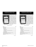
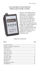
354 PRECISION AIRSPEED TESTER
OPERATING INSTRUCTIONS
354 PRECISION AIRSPEED TESTER
OPERATING INSTRUCTIONS
Meriam’s new Model 354 provides accurate Airspeed Indication and
Pitot System Leak Testing at the stroke of a key. The 354 is microprocessor based and has ± 0.05% of full scale accuracy including all effects of linearity, repeatability, hysteresis and temperature over the
range of 23ºF to 122°F. Airspeed can be displayed in knots, mph, or
km/h. Resolution of airspeed units is to the nearest tenth.Other display options include user selectable pressure units in inches of H2O,
inches of Hg, PSI or millibars. A leak test feature is included in the
354 to allow trouble shooting aircraft pitot systems. For convenient rezeroing of the unit, a “ZERO” key is included. The combination of
Airspeed Indication, Leak Testing and Accuracy makes the 354 a
great instrument for maintaining airspeed indicators and pitot systems.
TABLE OF CONTENTS
TABLE OF CONTENTS
Subject
Page
Keypad functions -----------------------------------------------------1
Measure Mode --------------------------------------------------------2
Program Mode --------------------------------------------------------2
Units Select ---------------------------------------------------------2
Damp Rate Select--------------------------------------------------4
Auto Shut Off ------------------------------------------------------5
User Info Select / Start-up Header information ---------------6
Contrast Select -----------------------------------------------------8
Battery change-out / PITOT and STATIC connections ---------9
Accuracy Verification / Re-calibration-------------------------- 10
Specifications ------------------------------------Inside Back Cover
F/N 354:440-2
04/24/2000
354oper 2 cover Apr 24 2...
page 1
Subject
Page
Keypad functions -----------------------------------------------------1
Measure Mode --------------------------------------------------------2
Program Mode --------------------------------------------------------2
Units Select---------------------------------------------------------2
Damp Rate Select--------------------------------------------------4
Auto Shut Off ------------------------------------------------------5
User Info Select / Start-up Header information ---------------6
Contrast Select -----------------------------------------------------8
Battery change-out / PITOT and STATIC connections ---------9
Accuracy Verification / Re-calibration-------------------------- 10
Specifications ------------------------------------Inside Back Cover
F/N 354:440-2
04/24/2000
Thursday, June 14, 2001 09:03
KEYPAD FUNCTIONS
KEYPAD FUNCTIONS
ON/OFF & BACKSPACE KEY
Turns the tester on and then turns it off from the Measure
Mode. Also serves as a backspace key when editing in the
Program Mode. The backspace function takes the user out
of a programmable register without changing the previous
setting. Pressing this key repeatedly will return the user to the
Measure Mode and then shut off the tester.
LEAK & UP ARROW KEY
In the Measure Mode activates and deactivates the LEAK
function per established guidelines. After an aircraft’s pitot
system is pressurized to a desired level, LEAK starts a 60
second settling time countdown. A 60 second leak test
follows displaying starting airspeed in upper right and current airspeed
in upper left. Leak in KNOTS /minute or MPH/minute is displayed
after test period. Up arrow
key is used to scroll through the
programmable registers menu when the unit is in the Program Mode.
Once a programmable register is selected the up arrow can be used
to edit that register.
ZERO & DOWN ARROW KEY
In the Measure Mode activates the ZERO function. A
“ZERO IN PROGRESS” message is displayed with a
countdown from 9 to 0 to indicate proper performance.
Down arrow
key is used to scroll through the program
registers menu when the unit is in the Program Mode. Once a
programmable register is selected the down arrow
can be used to
edit that register.
PRGM & ENTER KEY
Puts the tester into Program Mode from Measure Mode.
When in the Program Mode, pressing this key selects the
programmable register to be edited. After the register has
been edited, pressing the PRGM key enters the new setting into the
tester’s non-volatile memory. This key also acts as a forward space
key when editing user input such as the header name.
1
354oper 2 Apr 24 2000.pu...
page 1
1
Thursday, June 14, 2001 09:05
MEASURE MODE
MEASURE MODE
The Measure Mode is the tester’s start up mode. Measured airspeed
or pressure is displayed in user selected units.
The Measure Mode is the tester’s start up mode. Measured airspeed
or pressure is displayed in user selected units.
PROGRAM MODE
PROGRAM MODE
The Program Mode is used to configure the tester for Measure
Mode operation. The configurable registers that are found in the
Program Mode are Units Select, Damp Rate Select, User Info Select,
Contrast Select and Exit. The tester can be put into the Program
Mode at any time during Measure Mode operation by pressing the
PRGM key. The top line of the display will read “PROGRAM
MODE”. The bottom line will read “UNITS SELECT”. Press the up
or down arrow keys to scroll through the Program Mode to the
desired register.
UNITS SELECT
UNITS SELECT
The standard engineering units available on the Precision Airspeed
Tester are the following:
The standard engineering units available on the Precision Airspeed
Tester are the following:
1. KNOTS
2. MPH
3. KM / H
4. INCHES OF H2O
5. INCHES OF Hg
6. PSI
7. MILLIBARS
To change the engineering unit of measure the tester should be “ON”
and in the Measure Mode. Then use the following steps:
Keystroke
Display
1. KNOTS
2. MPH
3. KM / H
4. INCHES OF H2O
5. INCHES OF Hg
6. PSI
7. MILLIBARS
To change the engineering unit of measure the tester should be “ON”
and in the Measure Mode. Then use the following steps:
Keystroke
Display
1. Press PRGM key.
Top line reads “PROGRAM
MODE” and bottom line reads
“UNITS SELECT”.
1. Press PRGM key.
Top line reads “PROGRAM
MODE” and bottom line reads
“UNITS SELECT”.
2. Press ENTER key (right
arrow).
Top line reads “UNITS SELECT”
and bottom shows current
engineering unit.
2. Press ENTER key (right
arrow).
Top line reads “UNITS SELECT”
and bottom shows current
engineering unit.
2
354oper 2 Apr 24 2000.pu...
page 2
2
Thursday, June 14, 2001 09:05
3. Press up or down
arrow key until desired
engineering unit is displayed.
Engineering units on bottom line
of display change.
3. Press up or down
arrow key until desired
engineering unit is displayed.
Engineering units on bottom line
of display change.
4. Press ENTER key (right
arrow) to select desired
engineering unit.
Top line reads “PROGRAM
MODE” and bottom line reads
“UNITS SELECT”.
4. Press ENTER key (right
arrow) to select desired
engineering unit.
Top line reads “PROGRAM
MODE” and bottom line reads
“UNITS SELECT”.
5. Press the backspace
key.
Display returns to Measure Mode
in new engineering unit.
5. Press the backspace
key.
Display returns to Measure Mode
in new engineering unit.
arrow
3
354oper 2 Apr 24 2000.pu...
page 3
arrow
3
Thursday, June 14, 2001 09:05
DAMP RATE SELECT
DAMP RATE SELECT
Adjustable damping is available to steady the display when measuring
pulsating airspeed or pressure. The Precision Airspeed Tester has
damping rates of 0.1, 0.2, 0.5, 1, 2, and 5 seconds. Damping is done
by averaging new data from the pressure sensor against previously
collected data. The microprocessor collects data from the sensor every
0.1 seconds. When set at 0.1 seconds, the display updates every 0.5
seconds showing the current 0.1 second pressure reading. When set at
5 seconds, the display updates every 0.5 seconds showing the average
of the previous 5 seconds’ readings. Therefore, at this setting it takes 5
seconds from the time pressure is changed until the tester displays the
actual applied pressure. To set the damp rate follow these keystrokes:
Keystroke
Display
Keystroke
Display
1. From the Measure Mode,
press the PRGM key.
Top line reads “PROGRAM
MODE” bottom line reads
“UNITS SELECT”.
1. From the Measure Mode,
press the PRGM key.
Top line reads “PROGRAM
MODE” bottom line reads
“UNITS SELECT”.
2. Press the up
key.
Bottom line reads “DAMP RATE
SELECT”.
2. Press the up
key.
Bottom line reads “DAMP RATE
SELECT”.
3. Press ENTER key (right
arrow).
Top line reads “DAMP RATE
SELECT”, bottom line reads the
current damp rate.
3. Press ENTER key (right
arrow).
Top line reads “DAMP RATE
SELECT”, bottom line reads the
current damp rate.
4. Press the up or down
arrow keys to change to
desired rate.
Bottom line shows new damp rate
in seconds.
4. Press the up or down
arrow keys to change to
desired rate.
Bottom line shows new damp rate
in seconds.
5. Press ENTER key (right
arrow).
Selects damp rate, top line reads
“PROGRAM MODE”, bottom
line reads “UNITS SELECT”.
5. Press ENTER key (right
arrow).
Selects damp rate, top line reads
“PROGRAM MODE”, bottom
line reads “UNITS SELECT”.
6. Press the backspace
Returns to Measure Mode.
6. Press the backspace
Returns to Measure Mode.
arrow
arrow.
4
354oper 2 Apr 24 2000.pu...
page 4
arrow
arrow.
4
Thursday, June 14, 2001 09:05
AUTO SHUT-OFF
AUTO SHUT-OFF
Enabling the Auto Shut-Off feature allows the tester to turn itself off
after a user selected period of keypad inactivity. Selectable options
include DISABLED, 10 Minutes, 20 Minutes, 30 Minutes, 60 Minutes
and 90 Minutes. Disabling this feature limits the Pitot Display to
being turned off by using the ON/OFF key only. Units are shipped
from the factory with the Auto Shut-Off set for 10 Minutes. To change
the auto shut-off setting, follow the steps below.
Keystroke
Display
Keystroke
Display
1. From the Measure Mode,
press the PRGM key.
Top line reads “PROGRAM
MODE”, bottom line reads
“UNITS SELECT”.
1. From the Measure Mode,
press the PRGM key.
Top line reads “PROGRAM
MODE”, bottom line reads
“UNITS SELECT”.
2. Press up
Top line reads “PROGRAM
MODE”, bottom line reads
“USER INFO SELECT”.
2. Press up
Top line reads “PROGRAM
MODE”, bottom line reads
“USER INFO SELECT”.
3. Press ENTER key (right
arrow), then up arrow key
three times.
Top line reads “AUTO SHUTOFF”, bottom reads “ENTER TO
SELECT”.
3. Press ENTER key (right
arrow), then up arrow key
three times.
Top line reads “AUTO SHUTOFF”, bottom reads “ENTER TO
SELECT”.
4. Press ENTER key (right
arrow), then the up or
down arrow keys until
desired shut-off time is shown.
Top line reads “AUTO SHUTOFF”, bottom line toggles to
“DISABLED”, “10 Minutes”, “20
Minutes”, “30 Minutes”, “60
Minutes” and “90 Minutes”.
4. Press ENTER key (right
arrow), then the up or
down arrow keys until
desired shut-off time is shown.
Top line reads “AUTO SHUTOFF”, bottom line toggles to
“DISABLED”, “10 Minutes”, “20
Minutes”, “30 Minutes”, “60
Minutes” and “90 Minutes”.
5. Press ENTER key (right
arrow).
Desired Auto Shut-Off time is
selected, top line reads “AUTO
SHUT-OFF”, bottom reads
“ENTER TO SELECT”.
5. Press ENTER key (right
arrow).
Desired Auto Shut-Off time is
selected, top line reads “AUTO
SHUT-OFF”, bottom reads
“ENTER TO SELECT”.
6. Press the backspace
key twice.
Returns to Measure Mode.
6. Press the backspace
key twice.
Returns to Measure Mode.
arrow key twice.
arrow
5
354oper 2 Apr 24 2000.pu...
page 5
arrow key twice.
arrow
5
Thursday, June 14, 2001 09:05
USER INFO SELECT
USER INFO SELECT
The User Info Select register is designed to provide the user with
information on the hardware and software in the tester. This register
stores information on the sensor’s serial number, software version, date
of last calibration, Auto Shut-Off status and the instrument Start-Up
Header. This Header appears on the top display line when the tester is
turned on. The factory setting of the Header is “MERIAM INSTR.”
but can be edited to show a custom alpha-numeric string as desired by
the user. To view or configure any Unit Info Select register, follow the
keystrokes listed below.
Display
Keystroke
Display
Keystroke
1. From the Measure Mode,
press the PRGM key.
Top line reads “PROGRAM
MODE”. Bottom line reads
“UNITS SELECT”
1. From the Measure Mode,
press the PRGM key.
Top line reads “PROGRAM
MODE”. Bottom line reads
“UNITS SELECT”
2. Press the up
two times.
Bottom line changes to “USER
INFO SELECT”
2. Press the up
two times.
Bottom line changes to “USER
INFO SELECT”
3. Press the ENTER key ( ).
Bottom line shows serial number.
3. Press the ENTER key ( ).
Bottom line shows serial number.
4. Press the up
arrow key.
Software version number shown.
4. Press the up
arrow key.
Software version number shown.
5. Press the up
arrow key.
Calibration date shown.
5. Press the up
arrow key.
Calibration date shown.
6. Press the up
arrow key.
Top line reads “AUTO SHUT
OFF”, bottom line reads “ENTER
TO SELECT”.
6. Press the up
arrow key.
Top line reads “AUTO SHUT
OFF”, bottom line reads “ENTER
TO SELECT”.
7. To set the AUTO SHUT-OFF
see steps 4 - 6 on page 5.
7. To set the AUTO SHUT-OFF
see steps 4 - 6 on page 5.
8. To edit the Header, press the
up arrow key .
Top line reads “HEADER
NAME”, bottom line reads
“MERIAM INSTR.”, cursor
flashes at bottom left.
8. To edit the Header, press the
up arrow key .
Top line reads “HEADER
NAME”, bottom line reads
“MERIAM INSTR.”, cursor
flashes at bottom left.
arrow key
6
354oper 2 Apr 24 2000.pu...
page 6
arrow key
6
Thursday, June 14, 2001 09:05
9. Press the up or down
arrow keys to set the
alpha-numeric value.
Displays a number between 0 and
9, a letter from A to Z, / or a
blank space.
9. Press the up or down
arrow keys to set the
alpha-numeric value.
Displays a number between 0 and
9, a letter from A to Z, / or a
blank space.
10. Press ENTER key (right
arrow) to accept the selected
value.
Cursor advances one space to
right.
10. Press ENTER key (right
arrow) to accept the selected
value.
Cursor advances one space to
right.
11. Repeat steps 11 and 12
until the desired Header
is shown.
11. Repeat steps 11 and 12
until the desired Header
is shown.
12. If an error is made, press
the back arrow key until
cursor is over the incorrect
value. Follow step 9 - 11 to
correct. Press the right
arrow to advance the cursor
without changing values.
Corrected value is displayed.
12. If an error is made, press
the back arrow key until
cursor is over the incorrect
value. Follow step 9 - 11 to
correct. Press the right
arrow to advance the cursor
without changing values.
Corrected value is displayed.
13. When Header is complete
press the PRGM key to
advance cursor to line end.
Cursor flashes at bottom right.
13. When Header is complete
press the PRGM key to
advance cursor to line end.
Cursor flashes at bottom right.
14. Press ENTER key (right
arrow).
Top line reads “PROGRAM
MODE” bottom reads “UNITS
SELECT”.
14. Press ENTER key (right
arrow).
Top line reads “PROGRAM
MODE” bottom reads “UNITS
SELECT”.
15. Press the backspace
key.
Returns to Measure Mode.
15. Press the backspace
key.
Returns to Measure Mode.
arrow
7
354oper 2 Apr 24 2000.pu...
page 7
arrow
7
Thursday, June 14, 2001 09:05
CONTRAST SELECT
CONTRAST SELECT
The Contrast Select register allows the user to adjust the character
contrast of the LCD display to provide the best visibility for the
ambient conditions. If during the contrast adjustment an error is made,
pressing the backspace
key returns the display to the previous
contrast setting. To adjust the contrast follow the keystrokes below:
Keystroke
Display
Keystroke
Display
1. From the Measure Mode
press the PRGM key.
Top line reads “PROGRAM
MODE” bottom reads “UNITS
SELECT”.
1. From the Measure Mode
press the PRGM key.
Top line reads “PROGRAM
MODE” bottom reads “UNITS
SELECT”.
2. Press the up
three times.
Bottom line reads “CONTRAST
SELECT”.
2. Press the up
three times.
Bottom line reads “CONTRAST
SELECT”.
3. Press ENTER key (right
arrow).
Top line reads “CONTRAST
ADJUST”, bottom line shows a
numeric value.
3. Press ENTER key (right
arrow).
Top line reads “CONTRAST
ADJUST”, bottom line shows a
numeric value.
4. Press up arrow to decrease
contrast or down arrow to
increase the contrast.
LCD lightens or darkens
depending on value set.
4. Press up arrow to decrease
contrast or down arrow to
increase the contrast.
LCD lightens or darkens
depending on value set.
5. Press the PRGM key.
Accepts selected setting, top line
reads “PROGRAM MODE”,
bottom reads “UNITS SELECT”.
5. Press the PRGM key.
Accepts selected setting, top line
reads “PROGRAM MODE”,
bottom reads “UNITS SELECT”.
6. Press backspace
Returns to Measure Mode.
6. Press backspace
Returns to Measure Mode.
arrow key
arrow key.
8
354oper 2 Apr 24 2000.pu...
page 8
arrow key
arrow key.
8
Thursday, June 14, 2001 09:05
CHANGING THE BATTERY
CHANGING THE BATTERY
The tester is powered by a 9 volt alkaline (or lithium) battery. When
the output of the battery under load drops below 6.5 volts the display
flashes “LOW POWER DETECT” and “REPLACE BATTERY”. To
replace the battery, locate the battery compartment in the bottom rear
of the tester. Push down on the small rectangular area on the battery
cover and slide the cover out the bottom of the unit. Pull the battery
connector off the battery terminals. Plug the new battery into the
connector and install in the compartment. Slide the battery cover on
until the locking clip locks into the tester housing.
PITOT AND STATIC CONNECTIONS
PITOT AND STATIC CONNECTIONS
1/8” FNPT bulkhead connections are provided on the upper end of the
Precision Airspeed Tester. The left hand connection is the high
pressure side of the differential pressure sensor and is labeled
“PITOT”. The right hand connection is labeled “STATIC” and is the
low pressure side. The connections will allow the user to check
airspeed indicators under conditions of simulated altitude if desired.
To do this, apply a vacuum pressure to each connection and then
isolate the “PITOT” side from the vacuum source. Then increase the
pressure applied to the “PITOT” side with a pressure source. The
resulting difference between “PITOT” and “STATIC” pressures will be
displayed as airspeed under simulated altitude conditions.
When using the 354 Precision Airspeed Tester for other pressure
measurements, be sure to use the “PITOT” connection for the high
pressure. If measuring gauge pressure for example, simply vent the
“STATIC” side to atmosphere and apply up to 200” H2O gauge (7.22
PSIG) to the high side labeled “PITOT”. If measuring vacuum
pressures down to -200” H2O gauge (-7.22 PSIG), vent the “PITOT”
side to atmosphere and apply the vacuum to the “STATIC” side.
9
354oper 2 Apr 24 2000.pu...
page 9
9
Thursday, June 14, 2001 09:05
ACCURACY VERIFICATION / RE-CALIBRATION
ACCURACY VERIFICATION / RE-CALIBRATION
The Precision Airspeed Tester’s accuracy can be verified using a
±0.01% of reading deadweight tester. The tester should be checked at
a minimum of four test points: 25%, 50%, 75% and 100% of the units
range (200” H20). Before performing the evaluation, consider the
following information.
The Precision Airspeed Tester’s accuracy can be verified using a
±0.01% of reading deadweight tester. The tester should be checked at
a minimum of four test points: 25%, 50%, 75% and 100% of the units
range (200” H20). Before performing the evaluation, consider the
following information.
1. Use the User Unit Select option in Program Mode to match the
Precision Airspeed Tester units to the deadweight tester units. Be sure
to match the temperature reference of the deadweight tester to the
Precision Airspeed Tester temperature reference (60° F for inches H20
and 0° C for inches Hg; PSI and Millibars have no reference).
2. Correct the deadweight tester readings for ambient temperature
when it is different from the reference temperature. The Precision
Airspeed Tester does this automatically.
2. Correct the deadweight tester readings for ambient temperature
when it is different from the reference temperature. The Precision
Airspeed Tester does this automatically.
3. The local gravity where the evaluation is being performed must be
corrected for on the deadweight tester. Standard gravity reference is
980.665 cm/sec/sec (45° north latitude at sea level).
3. The local gravity where the evaluation is being performed must be
corrected for on the deadweight tester. Standard gravity reference is
980.665 cm/sec/sec (45° north latitude at sea level).
4. Make sure there are no leaks in the system.
4. Make sure there are no leaks in the system.
This evaluation will confirm whether the tester is operating within its
accuracy specification throughout the operating temperature range. If
found to be out of specification, the tester must be returned to the
factory for NIST traceable re-calibration. The Smart Manometer
cannot be re-calibrated in the field. Contact the Meriam Instrument
distributor in your area or call the factory at the number listed below
for a Return Material Authorization (RMA) number.
Meriam Instrument
10920 Madison Ave.
Cleveland, OH 44102
Ph. (216) 281-1100
Fax (216) 281-0228
10
354oper 2 Apr 24 2000.pu...
page 10
Meriam Instrument
10920 Madison Ave.
Cleveland, OH 44102
Ph. (216) 281-1100
Fax (216) 281-0228
10
Thursday, June 14, 2001 09:05
PRODUCT SPECIFICATIONS
MODEL NUMBER AND RANGE:
354-DN0200
0-200 inches H2O
10-514 knots
PRODUCT SPECIFICATIONS
MODEL NUMBER AND RANGE:
354-DN0200
0-200 inches H2O
10-514 knots
NIST TRACEABLE ACCURACY:
± 0.05% of F.S. (F.S. = 200 inches H2O)
NIST TRACEABLE ACCURACY:
± 0.05% of F.S. (F.S. = 200 inches H2O)
RECOMMENDED RECERTIFICATION PERIOD: 1 Year
RECOMMENDED RECERTIFICATION PERIOD: 1 Year
LEAK: Test function per the following guidelines:
(1) 60 second settling time countdown.
(2) during the next 60 seconds, the display holds the initial
altitude and displays the current altitude, yielding leak
information.
(3) the final display shows the 60 second leak rate in knots per
minute, MPH per minute or km / h per minute.
TEMPERATURE :
Storage:
Operating:
TEMPERATURE :
Storage:
Operating:
-40 °F to 140 °F (-40 °C to 60 °C)
23 °F to 122 °F (-5 °C to 50 °C)
-40 °F to 140 °F (-40 °C to 60 °C)
23 °F to 122 °F (-5 °C to 50 °C)
PRESSURE LIMITS: 400 inches H2O (15 PSI)
PRESSURE LIMITS: 400 inches H2O (15 PSI)
POWER: 9 volt Alkaline battery. 9 volt Lithium batteries can
also be used and are recommended below 32 ºF (0 °C).
POWER: 9 volt Alkaline battery. 9 volt Lithium batteries can
also be used and are recommended below 32 ºF (0 °C).
MEDIA COMPATIBILITY: Clean, dry, non-corrosive gases.
MEDIA COMPATIBILITY: Clean, dry, non-corrosive gases.
DISPLAY: 5 significant digit LCD (0.25" high).
2 line x 16 alphanumeric characters
DISPLAY: 5 significant digit LCD (0.25" high).
2 line x 16 alphanumeric characters
CONNECTIONS: 1/8" female NPT, 316ss. WEIGHT: 14 ounces
CONNECTIONS: 1/8" female NPT, 316ss. WEIGHT: 14 ounces
ENCLOSURE: (6.5" x 3.6" x 2.25") ABS plastic case.
ENCLOSURE: (6.5" x 3.6" x 2.25") ABS plastic case.
11
354oper 2 Apr 24 2000.pu...
page 11
11
Thursday, June 14, 2001 09:05