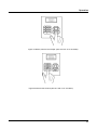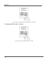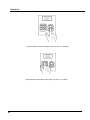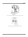
1
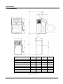
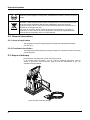
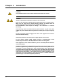
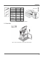
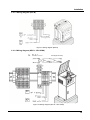
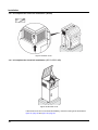
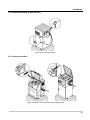
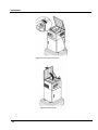
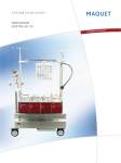
Operating instructions
Water sampler
MAXX
SP5 S /-B /-M /-F /-A /-MS
SP5 S-B-M-F-A-MS
0250031E
© MAXX GmbH, 2011. All rights reserved. Printed in Germany
May 2012
Remark:
Access code for program changes or changes of system settings:
Password:
Your password:
2
6299
Contents
Chapter 1 Specifications........................................................................................................................................ 5
1.1 Dimensions ................................................................................................................................................. 6
Chapter 2 General information ...................................................................................................................... 7
2.1 Safety information........................................................................................................................................ 7
2.1.1 Hazard information in this manual ................................................................................................. 7
2.1.2 Warning labels ........................................................................................................................................... 7
2.2 General information ..................................................................................................................................... 8
2.2.1 Areas of application ........................................................................................................................... 8
2.2.2 Functional description ........................................................................................................................ 8
2.3 Scope of delivery ................................................................................................................................................. 8
Chapter 3 Installation ........................................................................................................................ 10
3.1 Mechanical installation .............................................................................................................................. 11
3.1.1 Required tools .................................................................................................................................. 11
3.1.2 Select place of installation ............................................................................................................... 12
3.1.3 Unpacking................................................................................................................................................13
3.1.4 Setup .................................................................................................................................... 14
3.2 Electrical connections .......................................................................................................................... 16
3.2.1 Electrical installation .............................................................................................................. 17
3.2.1.1 Prepare the electrical installation (SP5 B) ..................................................................... 17
3.2.1.2 Prepare the electrical installation (SP5 S – SP5 S-MS) .................................................... 18
3.2.1.3 Wiring diagram (SP5 B) .................................................................................................... 19
3.2.1.4 Wiring diagram (SP5 S – SP5 S-MS)................................................................................. 19
3.2.1.5 Complete the electrical installation (SP5 B) ................................................................... ..20
3.2.1.6 Complete the electrical installation (SP5 S – SP5 S-MS) ................................................. 20
3.3 Commissioning of device .......................................................................................................................... 21
3.3.1 Hose connection .............................................................................................................................. 21
3.3.2 Set the single sample volume ...................................................................................................... 24
3.3.2.1 Plastic dosing vessel .......................................................................................................... 24
3.3.2.2 Glass dosing vessel .......................................................................................................... 26
3.3.2.3 Dosing vessel for flow-proportional sampling .................................................................... 26
3.3.2.4 Bypass dosing vessel ............................................................................................................. 27
3.3.2.5 Rinsing water connection and drain (SP5 S-F/SP5 S-A) ................................................... 28
3.3.2.6 Water circuit diagram (SP5 S-MS)...................................................................................... 29
3.3.3 Prepare sample containers (SP5 B, SP5 S, SP5 S-M, SP5 S-F, SP5 S-MS)............................. 29
3.3.4 Connect the device to the mains ....................................................................................................... 30
3
Chapter 4 Operation ............................................................................................................................................ 32
4.1 Control unit operation ................................................................................................................................ 32
4.1.1 Programming................................................................................................................................................. 32
4.1.1.1 Keyboard layout/function ........................................................................................................ 32
4.2 Normal operation ...................................................................................................................................... 34
4.2.1 Replace sample bottles (SP5 B, SP5 S, SP5 S-M, SP5 S-F)...................................................... 34
4.2.2 Sampling (SP5 S-A with 12 or 24 bottles) ...................................................................................... 36
4.2.3 Sampling (SP5 S-A with 2 or 4 bottles).......................................................................................... 40
Chapter 5 Maintenance and cleaning.......................................................................................................... 44
5.1 Maintenance tasks.................................................................................................................................................. 44
5.2 Cleaning..................................................................................................................................................... 44
5.2.1 Clean housing and distributor unit .................................................................................................. 44
5.2.2 Clean dosing vessel ......................................................................................................................... 46
5.3 Troubleshooting......................................................................................................................................... 48
5.3.1 Open the housing to change the fuse (SP5 B) ........................................................................ 48
5.3.2 Open the housing to change the fuse (SP5 S – SP5 S-MS)......................................................... 49
5.3.3 Change the fuse......................................................................................................................................49
5.3.4 Reassemble the housing (SP5 B)................................................................................................... 50
5.3.5 Reassemble the housing (SP5 S – SP5 S-MS) ............................................................................. 51
5.4 Decommissioning and storage of device ................................................................................................. 51
Chapter 6 Spare parts and accessories ............................................................................................... 52
6.1 Spare parts ...................................................................................................................................................... 52
Chapter 7 Warranty and liability............................................................................................................. 56
4
Chapter 1
Specifications
Electrics
Power supply
230 V/50 Hz., 16 A fuse
Power consumption
Approx. 350 VA
Environment
Medium temperature
0 to +40 °C
Ambient temperature
–20 to +40 °C
Suction height
<8m
General specifications
Maintenance requirements
Maintenance-free
Weight
See figure 10, page 15 and figure 11, page 15
Dimensions (h x w x d)
See figure 1
Certification
Certification
CE,
Sampling in accordance with ISO 5667 - 2/3-10
Subject to change without prior notice
5
Specifications
1.1 Dimensions
Z
X
2
l5
k14
6ghi
3
jdef
m
n
o
•
7
8t
9
p
q
rs 0
w
xzy
Y2
Y1
X
mm
Y1
mm
Y2
mm
Z
mm
SP5 B
760
1100
1640
725
SP5 S
605
1325
1895
645
SP5 S-M
605
1475
2030
645
SP5 S-F
605
1325
1895
645
SP5 S-F (23 bottles)
715
1415
2120
810
SP5 S-A (2–12 bottles)
605
1325
1895
645
SP5 S-A (24 bottles)
715
1415
2120
810
SP5 S-MS
1200
1690
2260
645
Figure 1 Dimensions
6
Chapter 2
General information
2.1 Safety information
Please read the entire manual before the equipment is unpacked, set up or operated. Pay
attention to all danger and caution statements. Personal injury or damage to the
equipment could occur if they are not observed.
To ensure that the protection provided by this equipment is not impaired, do not use or
install this equipment in any manner other than that specified in this manual.
2.1.1 Hazard information in this manual
DANGER
Indicates a potentially or imminently hazardous situation which, if not avoided,
will result in death or serious injury.
WARNING
Indicates a potentially or imminently hazardous situation which, if not
avoided, could result in death or serious injury.
CAUTION
Indicates a potentially or imminently hazardous situation that could result in
minor or moderate injury.
Important note: information that requires special emphasis.
Remark: information that supplements points in the main text.
2.1.2 Warning labels
Read all labels and notices attached to the equipment. Personal injury or damage to the
equipment could occur if they are not observed. Any symbol on the equipment will appear
along with a caution statement in the manual.
This symbol, if noted on the instrument, references the user manual for operation
and/or safety information.
This symbol, when noted on a product enclosure or barrier, indicates that a risk of
electrical shock and/or electrocution exists.
This symbol may appear on the product and indicates the need for protective goggles.
This symbol may appear on the product and identifies the connection point for the
protective ground.
7
General information
When this symbol appears on the product, it identifies the location of a fuse or a current
limiter.
Electrical equipment marked with this symbol may not be disposed of in European
domestic or public disposal systems after 12 August 2005. In conformity with European
local and national regulations (EU Directive 2002/96/EC), European electrical
equipment users must now return old or end-of-life equipment to the manufacturer for
disposal at no charge to the user.
For return for recycling, please contact the equipment manufacturer or supplier for
instructions on how to return end-of-life equipment, manufacturer-supplied electrical
accessories and all auxiliary items for proper disposal.
2.2 General information
2.2.1 Areas of application
The equipment is used for sampling aqueous liquids with a temperature between
0°C and 40°C.
2.2.2 Functional description
The equipment provides temporary storage for liquids of a specified volume so that they
can be analyzed.
2.3 Scope of delivery
The equipment is supplied with a tube and a short manual.
If you require further information, you can order the operating instructions (refer to
chapter 6 Spare parts and accessories, page 52) from the manufacturer or you can
download it from the Internet.
Figure 2 Scope of delivery (SP5 B)
8
General information
Figure 3 Scope of delivery (SP5 S – SP5 S-MS)
9
Chapter 3
Installation
DANGER
Only qualified experts should conduct the tasks described in this section.
DANGER
Select an appropriate installation location for the instrument.
Plan out the mechanical mount before positioning poles or drilling holes.
Make sure the mount has a sufficient bearing capacity. The dowels must be
selected and authorized according to the condition of the wall.
The manufacturer shall accept no liability if the instrument is installed
incorrectly.
Plan how to lay cables and tubes and their path in advance. Lay the hoses, data
cables and power cables without any bends so that they do not pose a tripping
risk.
Do not connect the electrical supply to the mains if the equipment has not been
wired and fused correctly.
Sufficiently protect the electrical power supply against short circuits.
For the external power supply, always connect a residual-current circuit
breaker·(trip current max.: 30 mA) between the mains and the system.
If the equipment is to be installed outdoors, place an overload protection between
mains and system.
Products intended by the manufacturer for outdoor use offer a higher level of
protection against the penetration of liquids and dust. If these products are
connected to a mains outlet with a cable and plug·rather than a permanently
connected cable, the plug and outlet are much more susceptible to liquid and dust
penetration. The operator must sufficiently protect the plug and outlet against
liquid and dust penetration in accordance with local safety regulations. If the
instrument is to be used outdoors, it must be connected to a suitable outlet with a
protection type of at least IP44 (splash protection).
10
Installation
3.1
Mechanical installation
DANGER
Select an appropriate installation location for the instrument.
Plan out the mechanical mount·before positioning poles or drilling holes. Make
sure the mount has a sufficient bearing capacity. The dowels must be selected
and authorized according to the condition of the wall.
The manufacturer shall accept no liability if the instrument is installed incorrectly.
Plan how to lay cables and tubes and their path in advance. Lay the hoses, data
cables and power cables without any bends so that they do not pose a tripping
risk.
.
Remark: For information on installation with optional accessories, refer to the relevant installation
instructions.
3.1.1 Required tools
Figure 4 Required tools
11
Installation
3.1.2 Select place of installation
≥ 50 mm
≥ 500 mm
X
Z
≥ 500 mm
1ab
3
c
def2
45
g
h
i6jkl
n
o
7m
Y2
2500 mm
Y1
X
mm
Y1
mm
Y2
mm
Z
mm
SP5 B
760
1100
1640
725
SP5 S
605
1325
1895
645
SP5 S-M
605
1475
2030
645
SP5 S-F
605
1325
1895
645
SP5 S-F
(23 Bottles)
715
1415
2120
810
SP5 S-A
(2–12 Bottles)
SP5 S-A
(24 Bottles)
605
1325
1895
645
715
1415
2120
810
1200
1690
2260
645
SP5 S-MS
Figure 5 Select place of installation
12
Ex
Installation
A
mm
B
mm
SP5 B
730
384
SP5 S
660
383
SP5 S-M
660
383
SP5 S-F
660
383
SP5 S-F
(23 bottles)
770
500
SP5 S-A
(2-12 bottles)
660
383
SP5 S-A
(24 bottles)
770
500
SP5 S-MS
1260
383
≥ Ø12 × 60 mm
Figure 6 Prepare place of installation
3.1.3 Unpacking
Figure 7 Move the equipment from the transport pallet (SP5 B)
13
Installation
Figure 8 Move the equipment from the transport pallet (SP5 S-SP5 S-MS)
3.1.4 Setup
kg
SP5 B
75
Figure 9 Set up the equipment (SP5 B)
14
Installation
Figure 10 Set up the equipment (SP5 Sxx)
SP5 S-MS
Figure 11 Set up the equipment (SP5 S-MS)
15
Installation
≥ 17mm
mm
> 80 Nm
≥ Ø12 x 60 mm
Figure 12 Align and secure the equipment
3.2 Electrical connections
DANGER
Only qualified experts should conduct the tasks described in this section.
DANGER
Do not connect the electrical supply to the mains if the equipment has not been
wired and fused correctly.
Sufficiently protect the electrical power supply against short circuits.
For the external power supply, always connect a residual-current circuit
breaker·(trip current max.: 30 mA) between the mains and the system.
If the equipment is to be installed outdoors, place an overload protection between
mains and system.
If the mains plug·of the power supply cable·is removed, a suitable double-pole oneway switch must be installed immediately next to the display unit·with clear labeling
for the power supply.
Products intended by the manufacturer for outdoor use offer a higher level of
protection against the penetration of liquids and dust. If these products are
connected to a mains socket with a cable and plug·rather than a permanently
.
16
Installation
Products intended by the manufacturer for outdoor use offer a higher level of
protection against the penetration of liquids and dust. If these products are
connected to a mains socket with a cable and plug·rather than a permanently
connected cable, the plug and socket are much more susceptible to liquid and
dust penetration. The operator must sufficiently protect the plug and outlet against
liquid and dust penetration in accordance with local safety regulations. If the
instrument is to be used outdoors, it must be connected to a suitable outlet with a
protection type of at least IP44 (splash protection).
.
3.2.1 Electrical installation
3.2.1.1 Prepare the electrical installation (SP5 B)
Figure 13 Loosen the screws and remove the cover (SB4 B)
Figure 14 Feed cable through (SB4 B)
17
Installation
3.2.1.2 Prepare electrical installation (SP5 S-SP5 S-MS)
Figure 15 Loosen the lid screws and open the lid (SP5 S-SP5 S-MS)
Figure 16 Lift up the cover (SP5 S-SP5 S-MS)
18
Installation
3.2.1.3 Wiring diagram (SP5 B)
Figure 17 Wiring diagram (SP5 B)
3.2.1.4 Wiring diagram (SP5 S - SP5 S-MS)
In:
Out:
DC 12 V
AC 250 V / 2 x 8 A
Pin assignment: relay
Figure 18 Wiring diagram (SP5 S – SP5 S-MS)
19
Installation
3.2.1.5 Complete the electrical installation (SP5 B)
Figure 19 Attach cover
3.2.1.6 Complete the electrical installation (SP5 S-SP5 S-MS)
Figure 20 Shut the cover
If the suction hose is not connected immediately, close the housing lid as described in
figure 24, page 22 and figure 25, page 23.
20
Installation
3.3 Commissioning of the device
Figure 21 Key storage location
3.3.1 Hose connection
Figure 22 Feed the suction hose through housing opening
21
Installation
Figure 23 Screw in the union nut
Figure 24 Close the lid
22
Installation
Figure 25 Screw down the lid tightly
Position the hoses in accordance with the following installation diagram.
H2S
Ex
8000 mm
1000 mm
>
]
–20–+40 °C
≤ 30.000 mm
<
0–+40 °C
> 50 µs
Figure 26 Installation diagram
23
Installation
3.3.2 Set the individual sample volume
3.3.2.1 Plastic dosing vessel
Figure 27 Release the plastic dosing vessel
Figure 28 Remove the plastic dosing vessel
24
Installation
V-Probe [mL]
= 150 mL
Figure 29 Cut the dosing tube to set the sample volume
Figure 30 Reinstall the plastic dosing vessel
25
Installation
3.3.2.2. Glass dosing vessel
100 ml = 100 ml
Figure 31 Displace the dosing tube vertically to set the sample volume
3.3.2.3 Dosing vessel for flow-proportional sampling
100 ml = 100 ml
Figure 32 Calibrate the flow-proportional dosing vessel via the service menu
26
Installation
,
Figure 33 The flow-proportional dosing vessel may only be used if there is NO counter pressure!
3.3.2.4 Bypass dosing vessel
Emergency overflow
4–20 L/Min.
+ mL
– mL
∆P = 0 [hPa, bar]
Figure 34 Set the sample volume of the bypass dosing vessel
27
Installation
3.3.2.5 Rinsing water connection and drain (SP5 S-F/SP5 S-A)
Hose nozzle: ¾“
Hose: Ø (internal) 25 mm
Figure 35 Rinsing water connection and drain (SP5 S-F)
Hose: Ø (internal) 25 mm
Hose nozzle: ¾“
Figure 36 Rinsing water connection and drain (SP5 S-A)
28
Installation
3.3.2.6 Water circuit diagram (SP5 S-MS)
Hose:
Ø (internal) 12 mm
Hose:
Ø (internal) 40 mm
∆P = 0 [hPa, bar ]
Figure 37 Water circuit diagram (SP5 S-MS)
3.3.3 Preparing sample containers (SP5 B, SP5 S, SP5 S-M, SP5 S-F, SP5 S-MS)
Figure 38 Put the empty bottles in the housing
29
Installation
Figure 39 Close the door
3.3.4 Connect the equipment to the mains
Make sure that:
30
·
the equipment has been fully prepared for commissioning
·
the values on the rating label correspond with those of the mains supply
·
the correct plug has been attached or the direct wire has been implemented correctly
·
the equipment can be put into operation without any risks.
Installation
Figure 40 Rating label
3m
3m
Figure 41 Possible connection configurations
31
Chapter 4 Operation
4.1 Control unit operation
All the equipment functions are software
software-controlled.
4.1.1 Programming
The menu structure is similar to the directory structure of a computer hard drive and is
divided into main menus and sub menus.
4.1.1.1 Keyboard layout/function
The equipment is programmed by the operator.
Figure 42 Control panel
The key functions are configured as follows to enable highly intuitive operation:
operation
Table 1 Key functions
Display help text
(in
in the case of selection fields, the cursor must be placed
on the left-hand side
Arrow key
Move from one menu item to the next menu selection
Arrow keys
Select the desired menu
Enter key
Move within a menu
Arrow keys
Selection within the menu
Arrow keys
Confirm the selection
(automatically marked with a ü)
Enter key
32
Operation
Table 1 Key functions (continued)
Enter/change values
Arrow keys
Confirm the entered values
Enter key
Return to the next superordinate menu level
Back key
Enter values
Numeric keypad
Initialise (Reset) of Display - Press together
Back-key
key + Enter
+
Wakeup sleepmode (press 5 sec. at least)
least
Back key
Back-
Restore factory settings (Display = „load
load factorysettings“)
factorysettings
Hold Back-key until boott process is finished
Back key
Back-
Example: A setting needs to be changed.
1. Press Enter.
Enter
The cursor flashes.
2. Use the arrow keys to move the cursor on the desired position.
3. Press the Enter key.
The selection is now confirmed and the program can be started.
Figure 43 Start the program
33
Operation
Depending on the program section
·
an activity is started
·
the next menu item is automatically selected.
or
Remark: General rule:
If you press the Back key
– the action is cancelled or
– the navigation takes one step back in the menu.
4.2 Normal operation
The described normal operation applies to several models
(e. g. SP5 B, SP5 S, SP5 S-M, SP5 S-F, SP5 S-A).
The SP5 B, SP5 S and SP5 S-A models are displayed as examples in the figures.
4.2.1 Replace the sample bottles (SP5 B, SP5 S, SP5 S-M, SP5 S-F)
Figure 44 Open the door
34
Operation
Figure 45 Remove full bottles
entnehmen
Figure 46 Replace with empty bottles
Flaschen hineinstellen
35
Operation
Figure 47 Close the door
4.2.2 Sampling (SP5 S-A with 12 or 24 bottles)
Figure 48 Press PAUSE to interrupt the running program (SP5 S-A with 12 or 24 bottles)
36
Operation
Figure 49 Select „Remove the sample“ (SP5 S-A with 12 or 24 bottles)
Figure 50 Select bottle number (SP5 S-A with 12 or 24 bottles)
37
Operation
Figure 51 Swivel out the sample faucet (SP5 S-A with 12 or 24 bottles)
Figure 52 Press the lever to open the sample faucet
(SP5 S-A with 12 or 24 bottles)
38
Operation
Figure 53 Swivel the lever back to close the sample faucet (SP5 S-A with 12 or 24 bottles)
Figure 54 Swivel in the sample faucet (SP5 S-A with 12 or 24 bottles)
39
Operation
Figure 55 Select “Continue program” (SP5 S-A with 12 or 24 bottles)
4.2.3 Sampling (SP5 S-A with 2 or 4 bottles)
Figure 56 Select “Pause” (SP5 S-A with 2 or 4 bottles)
40
Operation
Figure 57 Release the bottle holder (SP5 S-A with 2 or 4 bottles)
Figure 58 Pull out the bottle holder and take out sample (SP5 S-A with 2 or 4 bottles)
41
Operation
Figure 59 Select “Take out sample” (SP5 S-A with 2 or 4 bottles)
Figure 60 Select the bottle number (SP5 S-A with 2 or 4 bottles)
42
Operation
Figure 61 Push the bottle holder back in and secure (SP5 S-A with 2 or 4 bottles)
Figure 62 Select “Continue program” (SP5 S-A with 2 or 4 bottles)
43
Chapter 5
Maintenance and cleaning
DANGER
Only qualified experts should conduct the tasks described in this section.
WARNING
Please observe the following points for the use of chemicals and/or waste water:
Wear protective clothing:
– Laboratory coat
– Protective eyewear
– Rubber gloves
5.1 Maintenance work
The sampler is maintenance-free. Thus the operator does not need to carry out any
maintenance work.
5.2 Cleaning
5.2.1 Clean the housing and distributor
ATTENTION!
Manual rotation of the distributor can damage the drive.
Never rotate the distributor manually!
Clean the interior and exterior of the housing with a damp, lint-free cloth. Add commercial
household cleaner to the cleaning water as required.
44
Maintenance and cleaning
Figure 63 NEVER rotate the distributor unit manually
Figure 64 Clean the distributor unit
45
Maintenance and cleaning
5.2.2 Clean the dosing vessel
Figure 65 Release the dosing vessel
Figure 66 Remove the dosing vessel
46
Maintenance and cleaning
Figure 67 Clean the dosing vessel
Figure 68 Install the dosing vessel
47
Maintenance and cleaning
5.3 Troubleshooting
If the equipment does not function as required, check the fuse and replace if necessary.
5.3.1 Open the housing to change the fuse (SP5 B)
Figure 69 Open the lid and detach the cover (SP5 B)
Figure 70 Remove the safety cover (SP5 B)
48
Maintenance and cleaning
5.3.2 Open the housing to change the fuse (SP5 S – SP5 S-MS)
Open the housing lid as described in figure 15, page 18 and figure 16, page 18.
5.3.3 Change the fuse
5 x 20 mm
8 A (träge)
Figure 71 Fuse support
If the problem is not fixed after having checked or changed the fuse, please contact
the customer service.
49
Maintenance and cleaning
5.3.4 Reassemble the housing (SP5 B)
Figure 72 Install the safety cover (SP5 B)
Figure 73 Close the housing (SP5 B)
50
Maintenance and cleaning
5.3.5 Reassemble the housing (SP5 S – SP5 S-MS)
Close the housing lid as described in figure 20, page 20, figure 24, page 23 and figure 25,
page 23.
5.4 Decommissioning and storage of device
1.
Remove all liquids and, if necessary, solid matter from the feed and drain lines and
sample containers and clean as required.
2.
Close all active programs.
3.
Switch off the equipment.
51
Chapter 6 Spare parts and accessories
6.1 Spare parts
Description
Cat. No.
Short manual
0250029E
Detailed manual
0250028E
0080070
0069452
0080044
350 ml
Plastic dosing vessel
0900715
0069301
12 x 2
0069302
4 x 1,5
Figure 74 Plastic dosing vessel
52
Spare parts and accessories
0900053
0069401
0069402
0030004
350 ml
Glass dosing vessel (350 ml)
0900674
0069301
12 × 2 L
0069302
4 × 1,5
Figure 75 Glass dosing vessel (350 ml)
53
Spare parts and accessories
0900053
0069401
0069402
0030005
500 ml
Glass dosing vessel (500 ml)
0900243
0069301
12 x 2
0069302
4 x 1,5
Figure 76 Glass dosing vessel (500 ml)
54
Spare parts and accessories
0069402
0030027
250 ml
Bypass dosing vessel (glass)
0900239
0069301
12 x 2
0069317
20 x 2
Figure 77 Glass dosing vessel (flow-through)
55
Chapter 7
Warranty and liability
The manufacturer warrants that the product supplied is free of material and manufacturing
defects and undertakes the obligation to repair or replace any defective parts at zero cost.
The warranty period is 12 months from delivery resp. invoice date. Consumables and
damage caused by improper handling, poor installation or incorrect use are excluded from
this clause
With the exclusion of the further claims, the supplier is liable for defects including the lack
of assured properties as follows: all those parts that, within the warranty period calculated
from the day of the transfer of risk, can be demonstrated to have become unusable or that
can only be used with significant limitations due to a situation present prior to the transfer
of risk, in particular due to incorrect design, poor materials or inadequate finish will be
improved or replaced, at the supplier's discretion. The identification of such defects must
be notified to the supplier in writing without delay, however at the latest 7 days after the
identification of the fault. If the customer fails to notify the supplier, the product is
considered approved despite the defect. Further liability for any direct or indirect damages
is not accepted.
If instrument-specific maintenance and servicing work defined by the supplier is to be
performed within the warranty period by the customer (maintenance) or by the supplier
(servicing) and these requirements are not met, claims for damages due to the failure to
comply with the requirements are rendered void.
Any further claims, in particular claims for consequential damages cannot be made.
Consumables and damage caused by improper handling, poor installation or incorrect use
are excluded from this clause.
56
MAXX Mess- u. Probenahmetechnik GmbH
Hechinger Str. 41, D-72414 Rangendingen
Tel. +49(0)7471-98481 0 Fax +49(0)7471-98481 44
www.maxx-gmbh.com
email: [email protected]