1
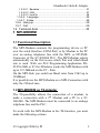
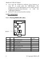
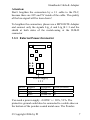
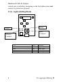
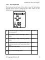
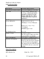
Operating instructions
english
for
MPI-Modem
Version 1.2
© Copyright 2006 by PI
Handbook Cable & Adapter
Contents
1 MPI-MODEM.............................................................. 3
1.1 Functional Description ..................................................3
1.2 MPI-MODEM as TS-Adapter ........................................3
1.3 Pin assignment .............................................................4
1.3.1
1.3.2
1.3.3
1.3.4
1.3.5
Pinning RS232 (PC-side) ............................................. 4
Pinning MPI (PLC-side)................................................ 6
External Power-Connector ........................................... 7
Light emitting Diods...................................................... 8
analogue Phone-Connector ......................................... 9
1.4 Connecting the MPI-Modem .......................................10
1.5 Display and Keyboard of the MPI-MODEM Cable......11
1.5.1 The Keyboard............................................................. 15
1.5.2 Main Menu.................................................................. 16
1.5.3 Info ............................................................................. 16
1.5.3.1 Version ........................................................................17
1.5.3.2 Signalquality................................................................17
1.5.3.3 Signallevel...................................................................17
1.5.4 Bus ............................................................................. 18
1.5.4.1 Adressen .....................................................................18
1.5.5 Config ......................................................................... 19
1.5.5.1 PG/PC .........................................................................19
1.5.5.2 MPI Accs .....................................................................20
1.5.5.2.1 Serial .............................................................................20
1.5.5.2.2 MODEM ........................................................................21
1.5.5.3 PPI-Accs .....................................................................21
1.5.5.3.1 Serial .............................................................................21
1.5.5.3.2 MODEM ........................................................................22
1.5.5.4 Modem ........................................................................22
1.5.5.4.1
1.5.5.4.2
1.5.5.4.3
1.5.5.4.4
1.5.5.4.5
1.5.5.4.6
1.5.5.4.7
1.5.5.4.8
1.5.5.4.9
Dial mode ......................................................................23
phonebook ....................................................................23
Baudrate .......................................................................24
Modemtype ...................................................................24
Speaker.........................................................................24
busy identification .........................................................25
ring counter ...................................................................25
extension.......................................................................26
outline code...................................................................26
1.5.5.5 MPI-BUS .....................................................................26
2
© Copyright 2006 by PI
Handbook Cable & Adapter
1.5.5.5.1 Baudrate .......................................................................27
1.5.5.5.2 HSA...............................................................................27
1.5.5.5.3 local Nr ..........................................................................28
1.5.5.6 Language ....................................................................28
1.5.5.7 Erase ...........................................................................28
1.5.6 Hang up...................................................................... 29
1.5.7 Call ............................................................................. 29
1.6 Technical data ............................................................30
1 MPI-MODEM
1.1 Functional Description
The MPI-Modem connects the programming device or PC
over the serial Interface (COM-Port) or by Modem to the PC
over an analog telephone line with the MPI- or DP/FMSConnector of the S7-300/400 PLC. The MPI-Modem selects
automatically on the first access which Port and which Baud
rate is used. With our PLC-Programming-Application PG95/PG-2000 or S7-for-Windows works the MPI-Modem with
up to 115.2kBaud on the PC - Side.
On the MPI-Side you could use Baud rates from 19k2 up to
12MBaud.
It is possible use the MPI-Modem on a MPI-Connection with
only the 2 Data-Lines.
1.2 MPI-MODEM as TS-Adapter
The TS-possibility allows the connection of a modem, to
make a connection with a 2nd Modem and a PC to a S7300/400. The MPI-Modem must be connected to an analoge
telephone line and the PLC .
To work with the MPI-Modem in his TS-function, you must
make the following actions:
© Copyright 2006 by PI
3
Handbook Cable & Adapter
1)
2)
You need the TeleService-software from Siemens in
your PC to work with the MPI-Modem. The
configuration of the MPI-Modem can be made with the
TeleService-software from Siemens
or with the
“MPI-Kabel Manager”.
On the PC side you need another modem.
1.3 Pin assignment
1.3.1 Pinning RS232 (PC-side)
RS232
Pin No. Notation Description
1
2
3
4
5
6
7
8
9
Shield
4
DCD
TXD
RXD
DSR
GND
DTR
CTS
RTS
RI
Data Carrier Detect
Transmitted Data
Received Data
Data Set Ready
Signal Ground
Data Terminal Ready
Clear to Send
Request to Send
Ring Indicator
On connector casing
Direction
(of cable)
Out
Out
In
In
Out
In
Out
In
© Copyright 2006 by PI
Handbook Cable & Adapter
The shield is connected with the RS232 connector via the
shield of the adapter casing. This MPI-Modem is designed to
be connected directly on a COM interface of a PC. The cable
can be lengthened by a 1:1-cable to the PC up to 15m
maximum. The cable should have a good quality and the
shield should be connected at both sides at the SUB-D case.
© Copyright 2006 by PI
5
Handbook Cable & Adapter
1.3.2 Pinning MPI (PLC-side)
MPI
Pin No. Notation
Description
1
2
3
4
5
6
7
8
9
Shield
Not Connected
Not Connected
Data line B
Request to Send from the PLC
Ground of the 5V
5V output
Not Connected
Data line A
Request to Send to the PLC
On connector casing
NC
NC
Ltg_B
RTS-AS
M5V
P5V
NC
Ltg_A
RTS-PG
Direction
(of cable)
BiDir.
In
In
Out
BiDir.
Out
The shield is attached with the MPI connector via the shield
of the adapter casing. To find directly attended PLC´s , RTSAS and M5V must be connected in the cable. P5V means a
output of the cable and works only as an output for a bustermination with resistors. This 5V output doesn’t drive any
load and have a 100R resistor inside his direction.
6
© Copyright 2006 by PI
Handbook Cable & Adapter
Attention:
Don’t lengthen the connection by a 1:1 cable to the PLC,
because there are 24V and 5V inside of the cable. The quality
of the bus-signal will be risen down!
To lengthen the connection, please use a MPI-NETZ-Adapter
and connect only the signals Ltg_A and Ltg_B 1:1 and the
shield at both sides of the metal-casing at the SUB-D
connector
1.3.3 External Power-Connector
Power-supply
123
Pin No.
1
2
3
Notation
P24V
GND
M24V
Description
24V Power
Ground
Ground 24V
In/Out (of Cable)
In
In
In
You need a power-supply +24VDC +/- 20%, 5VA. The
protective ground could also be connected to a cable-shoe on
the bottom of the powder-coated metal-case. The Powder© Copyright 2006 by PI
7
Handbook Cable & Adapter
coated case is isolating, mounting to the back-plane does not
connect to protective ground !
1.3.4 Light emitting Diods
Error
Power
MPI
Connect
Modem
Connect
LED
Power
Error
Phone connection established
MPI-Connection
8
Color
Green
Red
Yellow
Yellow
Position
upper left
upper right
lower left
lower right
© Copyright 2006 by PI
Handbook Cable & Adapter
1.3.5 analogue Phone-Connector
RJ-11/12
Pin No
1
2
3
4
5
6
Notation
NC
A’
A
B
B’
NC
Description
Not connected
Pass-through line A
Line A
Line B
Pass-through line B
Not connected
In/Out (of cable)
Out
In
In
Out
Analogue female Phone-Connector RJ-11/12, in China use
the DDE-Net (recommended).
© Copyright 2006 by PI
9
Handbook Cable & Adapter
1.4 Connecting the MPI-Modem
This MPI-Modem will be connected with the right connector
to the MPI- or the DP/FMS-Interface of the PLC. The MPIModem is power supplied with an external 24V voltage.
The left connector could connected to the programmingdevice or with an PC to the COM-Port.
When the MPI-Modem gets the power it shows the softwareversion in the display and begins with the test of its internal
components. On the display all relevant data is displayed.
The cable will find at a MPI-Connection the active baud rate
to the programming-device or to the PC in the first time of
communication and set his baud rate himself.
If you want to connect the cable to the 25-pin connector of
the PC, you can use an adapter (9 pin to 25 pin sub miniature
D-connector) to work with this port.
In the PC-Software you must adjust some parameters like the
baud rate (19,2 or 38,4 kbaud) and the connected COMPORT (COM1 or COM2) and the used adapter as ´TSAdapter´.
10
© Copyright 2006 by PI
Handbook Cable & Adapter
1.5 Display and Keyboard of the MPI-MODEM Cable
After Reset the Display shows all relevant Data of the PLCConnection.
Example for Display:
#02TD00▀|MODEM BE
!02AG04 |
In the first line there are displayed from left to right the
following Information:
1.) A Sharp „#“ with the number of connected active stations
on the MPI-Bus (in this example 2)
2.) The PC-Baud rate
MD
TD
115,2k or automatic Baudrate-Selection active
(Modem)
115,2k or automatic Baudrate-Selection active
(serial line)
MS
TS
19,2k (Modem)
19,2k (serial line)
Ms
Ts
38,4k (Modem)
38,4k (serial line)
mS
tS
57,6k (Modem)
57,6k (serial line)
© Copyright 2006 by PI
11
Handbook Cable & Adapter
3.) The station-number of MPI – II Cable (In S7-Manager
under „Extras / PG/PC-Interface“ with “Properties/Net/locale
station number“). The default is 0.
4.) When communicating a tiled bar (top is to PLC, bottom to
PG)
In the second line there are display from left to right the
following information:
1.) The first Char defines which type of PLC and which
connection is used
!
?
!
?
Active Station in MPI-Bus, directly connected
Active Station in MPI-Bus, far distance
Passive Station in MPI-Bus, directly connected
Passive Station in MPI-Bus, far distance
2.) The station-numbers of all active and connected stations
in the MPI-Bus. Every ¾ second another station is displayed.
3.) static Text „AG“ (means PLC)
4.) The PLC which is momentarily is connected to the PCSoftware (in our example is the Station 4 connected).
On the right side of the display, separated by “|”, is the
modem-state displayed.
In the first line the following messages could appear:
12
© Copyright 2006 by PI
Handbook Cable & Adapter
Message
MODEM READY
MODEM ERROR
NO ANSWER
RING
CON.END
CONNECT <Bd>
Description
The modem is booted and ready
The modem reports an error
The modem don’t send an answer
The modem is called
The connection is terminated
The modem is connected to a line with
the displayed Baudrate
NO CARRIER
The carrier is lost.
LINE BUSY
The phone-line or number is busy
BLACKLISTED
The called number is not allowed in
the modem
NR.DELAYED
The number called is too often or fast
redialed. The dialing is not allowed for
a minute
FAX
Fax-call detected
DATA
Data-call detected
UNKNOWN MESS. The modem generates an unknown
message
DIALING
The phone-number which is dialed is
shown in the bottom line
ENTRY EMPTY
The Fast-Access Entry is Empty
wrong PIN
The PIN-number configured is wrong
SIMCard wrong
The SIM-Card is not inserted, or not
correctly placed.
© Copyright 2006 by PI
13
Handbook Cable & Adapter
In the GSM-Version the display shows in the bottom line
additional information about the GSM-Network:
Display
SIM/PIN
RegDend
Unknown
ROAM:<xx>
GSM:<xx>
Srch:<xx>
Description
SIM Card not inserted or PIN-Number wrong
Registration denied in the GSM-network
Unknown state
Connection established to a provider which is
roaming. This could produce higher costs
Connection established to a provider.
Searching provider in GSM-network,
not yet found
At „ROAM“,“GSM“ and „Srch“ additionally the RecieveQuality is duisplayed (greater values are better).
-01
31
14
no recieve (antenna not connected?)
very bad
best and optimal
© Copyright 2006 by PI
Handbook Cable & Adapter
1.5.1 The Keyboard
The keyboard on the back of the cable is used for navigating
through menus and for configuring the cable. There are the
following keys sensing and colored:
↵
Es
⇑
⇐
⇒
⇓
↵
Confirm the input, change into a menu
or menu-point
ENTER
⇑
Increasing a value, selecting a menupoint
UP
⇓
Decreasing a value, selecting a menupoint
DOWN
⇐
Cancellation of a input/selection, the
selection is not saved, one menu-level
back
Go into a sub-menu
LEFT
⇒
Esc Go to state-message area
© Copyright 2006 by PI
RIGHT
ESC
15
Handbook Cable & Adapter
1.5.2 Main Menu
You select the main-menu with ENTER, with ENTER again
you reactivate the default-display
↵
MENU
Message
#02PD00▀
!02AG04
With UP/DOWN you could choose the following menupoints:
Message
Info
Bus
Config
Hang up
Call
activate default-display
Information over the MPI-MODEM cable
MPI-Bus information’s
Configuration of the cable
tells the modem to hang up
establishes a connection
1.5.3 Info
With RIGHT or ENTER you select the following sub-menu:
Info
Version
Info
Signal quality
Info
Signal level
16
© Copyright 2006 by PI
Handbook Cable & Adapter
1.5.3.1 Version
With RIGHT or ENTER you will enter the following display,
which will display the actual operation system version of the
cable:
Version
1.01
With LEFT or ENTER you will leave this sub-menu-point to
the menu info.
1.5.3.2 Signalquality
With RIGHT or ENTER you will enter the following display,
which will display the actual signal qullity of the connection:
Signalquality
With LEFT or ENTER you will leave this sub-menu-point to
the menu info.
1.5.3.3 Signallevel
With RIGHT or ENTER you will enter the following display,
which will display the actual signal quality of the connection:
Signallevel
With LEFT or ENTER you will leave this sub-menu-point to
the menu info.
© Copyright 2006 by PI
17
Handbook Cable & Adapter
1.5.4 Bus
With RIGHT or ENTER you enter the following sub-menu
which has only one element:
Bus
Address
With LEFT you leave this sub-menu to the main-menu. With
ENTER you enter the sub-menu.
1.5.4.1 Adressen
With RIGHT or ENTER you enter the following display,
which shows the connected stations on the MPI-Bus:
Adressen
D 018
With UP or DOWN you browse the addresses, where in the
second line the following chars are possible:
D
The MPI-MODEM Cable is connected directly to
this station
A
This station is active in the BUS
P
This station is passive like for example some
OP’s,FM or Profibus-Slaves.
18
© Copyright 2006 by PI
Handbook Cable & Adapter
With LEFT or ENTER you leave this sub-menu to the menu
info.
1.5.5 Config
With RIGHT or ENTER a Password request is displayed.
The Standard Password is “0”.With ENTER you enter the
following sub-menu where you could select the following
sub-menus:
Config
PG/PC
With UP/DOWN you could choose the following sub-menus:
PG/PC
Modem
MPI-BUS
Language
Set.Def
Password
For selecting the function of the Cable.
configure the Modem
Configuration of the MPI-Parameter
Selection of the Menu-Language
erases the Configuration, the DefaultProperties are loaded
Define a new Password
With LEFT you leave this sub-menu to the main-menu. With
ENTER you enter the sub-menu.
1.5.5.1 PG/PC
With RIGHT or ENTER you enter the following sub-menu
where you could select following menu-points::
PG/PC
MPI Accs
With UP/DOWN you select the following menu-points:
MPI Accs
The cable acts in a MPI-Bus
© Copyright 2006 by PI
19
Handbook Cable & Adapter
PPI Accs
The cable is connected to a S7-200
With LEFT you will leave this sub-menu to the menu mode.
1.5.5.2 MPI Accs
With RIGHT or ENTER you enter the following sub-menu
where you could select following menu-points::
MPI Accs
Serial
With UP/DOWN you select the following menu-points:
Serial
MODEM
Connect the PC over the serial line RS232
Connect the PC over Telephone-line with the
internal MODEM.
With LEFT you leave this sub-menu to the main-menu. With
ENTER you enter the sub-menu.
1.5.5.2.1
Serial
With RIGHT or ENTER you enter the following sub-menu
where you could select following menu-points::
Ser.Baud
19.2k
With UP/DOWN you select the following menu-points, with
ENTER the selection is used:
19.2k
38.4k
57.6k
115.2k
Auto
20
Baudrate 19200
Baudrate 38400
Baudrate 57600
Baudrate 115200
The MPI-Modem selects automatically the baudrate
© Copyright 2006 by PI
Handbook Cable & Adapter
With LEFT (Cancel) or ENTER (Select) you will leave this
Menu and go to PG/PC.
1.5.5.2.2
MODEM
With ENTER the Modem is the Accespoint.
1.5.5.3 PPI-Accs
With RIGHT or ENTER you enter the following sub-menu
where you could select following menu-points::
MPI-Accs
Serial
With UP/DOWN you select the following menu-points:
Serial
MODEM
Connect the PC over the serial line RS232
Connect the PC over Telephone-line with the
internal MODEM.
With LEFT you leave this sub-menu to the main-menu. With
ENTER you enter the sub-menu.
1.5.5.3.1
Serial
With RIGHT or ENTER you enter the following sub-menu
where you could select following menu-points::
Ser.Baud
9.6k
With UP/DOWN you select the following menu-points, with
ENTER the selection is used:
9.6k
19.2k
Baudrate 9600
Baudrate 19200
© Copyright 2006 by PI
21
Handbook Cable & Adapter
With LEFT you leave this sub-menu to the main-menu.
1.5.5.3.2
MODEM
With RIGHT or ENTER you enter the following sub-menu
where you could select following menu-points::
ModmBaud
9.6k
With UP/DOWN you select the following menu-points, with
ENTER the selection is used:
9.6k
19.2k
Baudrate 9600
Baudrate 19200
With LEFT you leave this sub-menu to the main-menu.
1.5.5.4 Modem
With RIGHT or ENTER you enter the following sub-menu
where you could select following menu-points::
Modem
dial mode
With UP/DOWN you select the following menu-points:
Dial mode
Phonebook
Baudrate
Modemtype
Speaker
Busy identify
Ring counter
Extension
Outline code
22
dial by tone or pulse
edit entries in the phonebook
Modem-baudrate over telephone line
select modemtype
Speaker loudness
select busy identify
autmatic connection
use extension
if extension then define the outline code
© Copyright 2006 by PI
Handbook Cable & Adapter
With LEFT you leave this sub-menu to the main-menu. With
ENTER you enter the sub-menu.
1.5.5.4.1
Dial mode
With RIGHT or ENTER you enter the following sub-menu
where you could select following menu-points::
Dial mode
Tone
With UP/DOWN you select the following menu-points, with
ENTER your selection is used:
tone
pulse
dialing with tones
dialing with pulses
1.5.5.4.2
phonebook
With RIGHT or ENTER you enter the following sub-menu
where you can choose the phonebook entry to edit.
phonebook entry:
1
Use UP und DOWN to select the phonebook entry. By
pressing ENTER you can edit the entry.
phonebook entry:
> <
© Copyright 2006 by PI
23
Handbook Cable & Adapter
With UP/DOWN/RIGHT/LEFT you can edit the phonebook
entry. ENTER saves your changes, ESC will cancel the
action.
1.5.5.4.3
Baudrate
With RIGHT or ENTER you enter the following sub-menu
where you could select following menu-points::
Baudrate
300 Bd
With UP/DOWN you select the following menu-points, with
ENTER your selection is used:
300
12000
26400
1200
14400
28000
automatic
1.5.5.4.4
2400
16800
31200
4800
19200
33600
7200
21600
9600
24000
The Modem selects the appropriate
baudrate by self.
Modemtype
With RIGHT or ENTER you enter the following sub-menu
where you could select following menu-points::
Modemtyp
D
With UP/DOWN you select the following menu-points, with
ENTER your selection is used:
D
USA
Auto
1.5.5.4.5
24
Germany
USA
Automatic Selection wich telephone type
is used.
Speaker
© Copyright 2006 by PI
Handbook Cable & Adapter
With RIGHT or ENTER you enter the following sub-menu
where you could select following menu-points::
Lautsprecher
Aus
With UP/DOWN you select the following menu-points, with
ENTER your selection is used:
Off
Silent
Middle
Loud
1.5.5.4.6
Speaker is off
Speaker is silent
Speaker is on normal Loudness
Speaker is at maximum Loudness
busy identification
With RIGHT or ENTER you enter the following sub-menu
where you could select following menu-points::
Busy identify
YES
With UP/DOWN you select the following menu-points, with
ENTER your selection is used:
YES
NO
1.5.5.4.7
busy identify is used
busy identiy is NOT used
ring counter
With RIGHT or ENTER you enter the following sub-menu
where you could select following menu-points::
Ring counter
1
With UP/DOWN you select the ring counter, the value can be
between 0 (no answer on call) to 9.
© Copyright 2006 by PI
25
Handbook Cable & Adapter
1.5.5.4.8
extension
With RIGHT or ENTER you enter the following sub-menu
where you could select following menu-points::
Extension
YES
With UP/DOWN you select the following menu-points, with
ENTER your selection is used:
YES
NO
1.5.5.4.9
extension is used
extension is NOT used
outline code
With RIGHT or ENTER you enter the following sub-menu
where you could select following menu-points:
Outline code
With UP/DOWN/RIGHT/LEFT you can select the extension
which is preceded before all outgoing calls. With ENTER the
selection is used.
1.5.5.5 MPI-BUS
With RIGHT or ENTER you enter the following sub-menu,
in which you could choose following sub-menus:
MPI-BUS
Baudrate
With UP/DOWN you could enter the following sub-menus:
Baudrate
HSA
26
MPI-Baud rate configuration, the baud rate
selected here is used, even when another is
selected over the PG/PC on connection to
PLC.
select highest station address
© Copyright 2006 by PI
Handbook Cable & Adapter
local Nr
select local stations address for the cable
with LEFT you leave this sub-menu to the menu config. With
ENTER you enter the sub-menu.
1.5.5.5.1
Baudrate
With RIGHT or ENTER you enter the following sub-menu:
MPI-Baud
187.5k
With UP/DOWN you could choose between the following
baud rates. With ENTER the baud rate is selected:
12M
6M
3M
1.5M
500k
187.5k
93.75k 45.45k 19.2k
from PC
the baudrate which is transfered from PC
is used
With LEFT (Cancel) or ENTER (Select) you leave the submenu to the menu MPI.
1.5.5.5.2
HSA
With RIGHT or ENTER you enter the sub-menu:
HSA
31
With UP/DOWN you could choose between the following
values, with ENTER you select the value:
126
63
31
© Copyright 2006 by PI
15
27
Handbook Cable & Adapter
With LEFT or ENTER you leave this sub-menu to the menu
MPI.
1.5.5.5.3
local Nr
With RIGHT or ENTER you enter the following Sub-Menu:
lokaleNr
0A
With UP/DOWN the local station number is
increased/decreased with one. With RIGTH/LEFT the station
number is increased/decreased by 16. The local station
number is displayed in hexadecimal.
With ENTER you leave this sub-menu to the menu MPI.
1.5.5.6 Language
With RIGHT or ENTER you enter the following sub-menu:
Language
German
With UP/DOWN you could select the following languages:
German
English
Language of menu is German
Language of menu is English
With LEFT you leave this Sub-Menu to the Menu config.
With ENTER you choose the language and the sub-menu is
leaved to config.
1.5.5.7 Erase
The default-configuration is saved to OnBoard-Flash with the
correct password.
28
© Copyright 2006 by PI
Handbook Cable & Adapter
1.5.6
Hang up
With RIGHT or ENTER you tell the modem to close an
active connection and to hang up.
1.5.7 Call
With RIGHT or ENTER you select the following sub-menu:
phonebook entry:
1
UP and DOWN selects the phonebook entry, with ENTER
the modem dials the number stored in the entry.
© Copyright 2006 by PI
29
Handbook Cable & Adapter
1.6 Technical data
Description
Technical specifications
Dimensions without cables 165 x 90 x 50mm (L x W x H)
Case type
Powder-coated, metallic case
(Isolating, connect protective
ground to connector on the
bottom of the Device with a
6.3mm cable-shoe or powerconnector)
Interfaces
To the MPI-BUS
RS485(19,2/93,5/187,5/
500kBaud, 1.5/3/6/12Mbaud)
To the PG/PC
RS232 19,2 / 38,4 / 57,6 /
115,2kBaud
MODEM upto 33.6k
To Telephone-line
Supply voltage
RJ-11/12
DC 24V +/- 20%
The 24V will be taken out of the
connected PLC or external.
5VA (Typ. I = 200mA at 24V)
The internal electronic (and
RS232) to the bus driver and also
to the 24V input are decoupled.
The shield from the MPI/PPI side
to the RS232 side are connected
through
Power disurpation
Galvanic decoupling
Order Description
MPI-Modem 3m
30
Order.No. 9352
© Copyright 2006 by PI