1
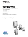
TURBOVAC
Turbomolecular pumps with grease-lubricated bearings
TURBOVAC 35 LS, 35 LS2
TURBOVAC 50
TURBOVAC 151, 151 C
TURBOVAC 361, 361 C
TURBOVAC 600 C
TURBOVAC 1000 C
and pumps modified by Oerlikon Leybold Vacuum
Operating Instructions GA05118_1502
idealvac.com
(505)872-0037
idealvac.com
Contents
Page
2
Important Safety Information
3
1
Description
6
1.1
Design and Operation
6
1.2
Supplied Equipment
6
1.3
Technical Data
7
1.4
Ordering Information
12
1.5
Operating environment and cooling
13
2
Transport and Storing
14
3
Installation
15
3.1
Conforming Utilisation
15
3.2
Ambient Conditions
15
3.3
Connecting the pump to the vacuum chamber
16
3.4
Forevacuum connection
20
3.5
Connecting the cooling
20
3.6
Connecting the purge gas and airing device
22
3.7
Connecting the TURBOTRONIK
23
4
Operation
24
4.1
Media Compatibility / Purge Gases
24
4.2
Start-up
25
4.3
Bakeout
26
4.4
Operation
26
4.5
Switching Off
26
4.6
Venting
27
5
Maintenance
29
5.1
Maintenance Intervals
29
5.2
Oerlikon Leybold Vacuum Service
29
5.3
Cleaning
30
5.4
Removing the pump from the system
30
6
Troubleshooting
31
7
Waste Disposal
33
EC Manufacturer’s Declaration
34
GA05118_1502 - 12/2006 - © Oerlikon Leybold Vacuum
Safety Information
Important Safety Information
Indicates procedures that must be strictly observed to prevent hazards to
persons.
Warning
Indicates procedures that must be strictly observed to prevent damage to, or
destruction of the product.
Caution
The Oerlikon Leybold Vacuum TURBOVAC have been designed for safe
and efficient operation when used properly and in accordance with these
Operating Instructions. It is the responsibility of the user to carefully read
and strictly observe all safety precautions described in this section and
throughout the Operating Instructions. The TURBOVAC must only be
operated in the proper condition and under the conditions described
in the Operating Instructions. It must be operated and maintained by
trained personnel only. Consult local, state, and national agencies regarding specific requirements and regulations. Address any further safety,
operation and/or maintenance questions to our nearest office.
Failure to observe the following precautions could result in serious
personal injury!
Mechanical hazards
Risk of injury!
Avoid exposing any part of the human body to the vacuum. Only handle
the pump when it is vented.
Warning
Turbopumps as described in the following operation manual contains a
high portion of kinetic energy due to their high rotational speed in combination with the specific rotor mass.
In case of a malfunction of the system for example rotor/stator contact or
even a rotor crash the rotational energy is released.
To avoid the destruction of the equipment and to prevent injuries of the
operating staff the leading European manufacturers of vacuum pumps
strictly recommend to follow the installation instructions as given in this
manual!
Never operate the pump (in bench tests, for instance) without its being
flanged to the vacuum chamber.
The small-flange connector for the high-vacuum flange at the TURBOVAC
50 is not strong enough to keep the pump from rotating if it should suddenly seize. Rotation of the pump can cause leaks in the forevacuum
line. Secure the pump additionally to prevent rotation in case it should
suddenly seize.
GA05118_1502 - 12/2006 - © Oerlikon Leybold Vacuum
3
Safety Information
Electrical hazards
Warning
Risk of injury!
Dangerous voltages are present at the mains connections. Before beginning with any maintenance or service work on the pump, disconnect the
pump from all power supplies.
Operate the pump only with the matching frequency converter and
connector line.
Voltages of up to 400 V will be present at the connection cable between
the frequency converter and the pump; mains voltage will be present at
the fan, the flange heater, the valves and their supply leads.
Route the conductors and cables so as to protect them from damage.
When the connector cable to the TURBOVAC is attached, the outputs of
the TURBOTRONIK frequency converter are not free of voltage.
Thermal hazards
Warning
Risk of injury!
The pump can become so hot during operation (> 70°C, 158 °F) as to
represent a burn hazard. Shield the hot components against contact.
Note the symbols on the pump pointing to the hazards, and in the case of
a hot pump wear the required protective clothing.
Hazards caused by materials and substances
Warning
The forevacuum line must be tight.
Hazardous gases could escape from leaks or the gases being pumped
could react with air or humidity.
Take the appropriate precautionary measures prior to opening the intake
or discharge connection if the pump has previously handled hazardous
gases.
If necessary, use gloves, a respirator and/or protective clothing and work
under an exhaust hood.
Risk of explosion!
The standard version of the pump is not suited for operation in
explosion hazard areas. Contact us before planning to use the pump
under such circumstances.
Contaminated parts can be detrimental to health and environment. Before
beginning with any work , first find out whether any parts are contaminated. Adhere to the relevant regulations and take the necessary precautions when handling contaminated parts.
4
GA05118_1502 - 12/2006 - © Oerlikon Leybold Vacuum
Safety Information
Failure to observe the following precautions could result in damage
to the pump!
Unauthorized opening of the pump or modifications of the mechanical or
electrical components of the pump void the warranty.
Caution
The pump must only be opened by such persons who have been authorised by Oerlikon Oerlikon Leybold Vacuum Vacuum to do so.
The rotor is precision balanced; any change whatsoever, such as loosening or bending any rotor component, will make re-balancing necessary.
Unless appropriate accessories and attachments are used, the TURBOVAC is not suitable for aggressive or corrosive media, or those containing
dust. When handling corrosive media the C version pump must be
operated with purge gas; when handling media containing dust, a finemesh filter must be installed.
Observe the information on media compatibility, to be found in Section
4.1.
Take care not to damage the plugs and coolant connections during movement.
Exposure of the pump to accelerating forces must be avoided or reduced
to such an extent that the rotor unit will not be excited by vibrations. In
the case of critical applications you must consult our Applications Dept.
first.
The references to diagrams, e. g. (1/2) consist of the Fig. No. and the Item
No. in that order.
Figures
We reserve the right to alter the design or any data given in these Operating
Instructions. The illustrations are not binding.
Retain the Operating Instructions for further use.
GA05118_1502 - 12/2006 - © Oerlikon Leybold Vacuum
5
Description
1
Description
1.1 Design and Operation
The TURBOVAC models 35 LS to 1000 are turbomolecular pumps featuring
grease-lubricated bearings. These units are engineered to pump vacuum
chambers down to pressures in the high-vacuum range. A TURBOTRONIK
frequency converter and a forevacuum pump are required for the operation of
the TURBOVAC.
1.2 Supplied Equipment
The TURBOVAC is shipped in a sealed PE bag which also contains a desiccant. The maximum effective life of the desiccant is one year.
TURBOVAC 35 LS / 35 LS2
The pumps are shipped without splinter guard or connection accessories.
TURBOVAC 50 to 1000
For high-vacuum port with ISO-K flange:
Splinter guard, centering ring with FPM sealing ring; outer ring.
For high-vacuum port with CF flange: Splinter guard.
For high-vacuum port with KF flange: Splinter guard, centering ring with FPM
O-ring and clamping ring.
For high-vacuum port with ANSI flange: Splinter guard.
Forevacuum port: Centering ring with O-ring and clamping ring.
Both the purge gas port and the airing port are blanked off for shipping.
In addition the pivoted threaded fittings used to make the coolant connection
are included as standard equipment for the TURBOVAC 151, 361 and 600; if
needed, they can be used to replace the hose nipples installed at the factory.
The electronic frequency converter and the connector cables required for
operation are not included as standard equipment with the pump.
——————————
PE = Polyethylene
FPM = Fluoroelastomer, resistant to temperatures of up to 150°C (300 °F)
6
GA05118_1502 - 12/2006 - © Oerlikon Leybold Vacuum
Description
1.3
Technical Data
Special Versions for Leak Detectors
TURBOVAC
35 LS
35 LS2
40 KF
40 KF
I · s-1
I · s-1
25
4.5
32
5.5
Max. gas throughput in permanent operation
with water cooling at 10-2 mbar,
He
mbar · I · s-1
0.25
0.25
1.5 · 103
70
2 · 104
600
1
6
16 KF
16 KF
TRIVAC D 2,5 E
Diaphragm pump
High-vacuum port
DN
Pumping speed
He, high vacuum
He, interstage vacuum
Max. idle compression
He, high vacuum
He, interstage vacuum
Max. forevacuum pressure for He
mbar
Forevacuum port
DN
Recommended forevacuum pump
Run-up time to 95% nominal speed
Weight, approx.
min
2
kg
2
Max. power consumption / at ultimate pressure W
Max. ambient temperature at operation
45 / 15
°C
45
High-vacuum port
Interstage vacuum
port
Forevacuum port
Electrical connection
TURBOVAC 35 LS and 35 LS2
GA05118_1502 - 12/2006 - © Oerlikon Leybold Vacuum
7
Description
TURBOVAC 50
High-vacuum port
DN
O-Ring sealed
40 KF
O-Ring sealed
63 ISO-K
Metal sealed
63 CF
Aluminium
Aluminium
Stainless steel
33
36
28
55
48
30
55
48
30
0.30
0.25
0.20
0.40
0.35
0.25
0.40
0.35
0.25
2 · 106
2 · 106
2 · 108
< 5 · 10-8
< 5 · 10-8
< 5 · 10-8
Pump housing
Pumping speed at
N2
He
H2
10-3
mbar
I · s-1
I · s-1
I · s-1
Max. gas throughput in permanent operation
with water cooling at 10-2 mbar
N2
mbar · I · s-1
He
mbar · I · s-1
H2
mbar · I · s-1
Max. idle compression N2
Ultimate pressure with TRIVAC D 2,5 E
mbar
Max. forevacuum pressure for N2
mbar
Forevacuum port
1 · 10-1
DN
16 KF
Recommended forevacuum pump
TRIVAC D 2,5 E
Run-up time to 95% nominal speed
min
2
Cooling water connection (hose nozzle)
(for Part No. 854 08)
mm
10
kg
2
Weight, approx.
Max. power consumption / at ultimate pressure W
45 / 15
Max. ambient temperature at operation
°C
55
Max. bakeout temperature at CF flange
°C
80
High-vacuum port
Forevacuum port
Electrical connection
TURBOVAC 50
8
GA05118_1502 - 12/2006 - © Oerlikon Leybold Vacuum
Description
TURBOVAC 151
TURBOVAC 361 / 361 C
High-vacuum port
DN
100 ISO-K / 100 CF
Pumping speed
s-1
·
· s-1
· s-1
· s-1
145
150
135
115
345
350
340
340
400
–
380
370
mbar · I · s-1
mbar · I · s-1
mbar · I · s-1
3
3
1.7
7.5
7.5
–
–
I
I
I
I
N2
Ar
He
H2
Max. gas throughput N2
Ar
H2
Compression
N2
He
H2
100 ISO-K • 100 CF 160 ISO-K • 160 CF
1 · 109
2 · 104
8 · 102
1 · 109
6 · 104
3 · 103
Ultimate pressure
mbar
< 1 · 10-10
< 1 · 10-10
Max. Inlet pressure (permanent)
with water cooling
mbar
5 · 10-2
5 · 10-2
Max. forevacuum pressure for N2
mbar
5 · 10-1
5 · 10-1
D 4 B to D 16 B
D 16 B to D 25 B
Recommended forevacuum pump
TRIVAC
Run-up time to 95% nominal speed
min
≈2
≈2
Forevacuum port
DN
25 KF
25 KF
Purge gas / vent port
DN
10 KF
10 KF
Cooling water connection (hose nozzle)
mm
10
10
kg
8
12
680 / 480
680 / 480
Weight, approx.
Max. power consumption / at ultimate pressure VA
Max. ambient temperature at operation
°C
55
55
Max. bakeout temperature at CF flange
°C
100
100
High-vacuum port
Electrical connection
Vent port
Connection
for water
cooling
Purge gas
port
Forevacuum port
TURBOVAC 151 C; TURBOVAC 361 C similar
GA05118_1502 - 12/2006 - © Oerlikon Leybold Vacuum
9
Description
TURBOVAC 600 C
160 ISO-K / CF 200 CF / 6“ ANSI 250 ISO-K
High-vacuum port
DN
Pumping speed
N2
He
H2
I · s-1
I · s-1
I · s-1
560
600
570
Max. gas throughput N2
Ar
mbar · I · s-1
mbar · I · s-1
<4
<4
-
> 109
2 · 104
1.1 · 103
-
mbar
< 10-10
< 10-10
Speed
rpm
36 ,000
36,000
Run-up time (freq. converter), approx.
min
4
9
Compression
160 ISO-K • 160 CF
TURBOVAC 1000 C
N2
He
H2
Ultimate pressure
850
-
1100
-
Max. Inlet pressure (permanent)
with water cooling
mbar
1 · 10-2
-
Max. forevacuum pressure for N2
mbar
5 · 10-2
5 · 10-2
Recommended forevacuum pump
at standard operation
at purge gas operation
TRIVAC
TRIVAC
D 25 B / 40 B
40 B
1150
-
TRIVAC D 40 B
Run-up time to 95% nominal speed
min
3
Forevacuum port
DN
40 KF
40 KF / 63 ISO-K
40 KF
40 KF / 63 ISO-K
Purge gas / vent port
DN
10 KF
10 KF1)
10 KF1)
10 KF1)
Cooling water connection (hose nozzle)
mm
10
11 / 102)
11
11 / 102)
Weight, approx.
kg
12
Max. power consumption /
at ultimate pressure
VA
680 / 480
Max. ambient temperature at operation
°C
55
55
Max. bakeout temperature at CF flange
°C
100
100
1) As of 1995 in some cases 16 mm KF
2) 11 mm with 40 mm type KF forevacuum port
10 mm with 63 mm type ISO-K forevacuum port
10
GA05118_1502 - 12/2006 - © Oerlikon Leybold Vacuum
-
25
-
Description
A
A
C
B
C
D
D
B
E
F
E
F
TURBOVAC 600 C
TURBOVAC 1000 C
A
B
C
D
E
F
High-vacuum port
Forevacuum port
Vent port
Purge gas port
Connection for water cooling
Electrical connection
Fig. 2
GA05118_1502 - 12/2006 - © Oerlikon Leybold Vacuum
11
Description
1.4 Ordering Information
TURBOVAC
35 LS 35 LS 2
50
151
151 C
361
361 C
DN 100 ISO-K
856 31
856 35
856 70
800150V00053)
856 75
800150V00184)
DN 100 CF
856 32
103 41
856 71
600 C
1000 C
800150V0015
855 351)
855 382)
800150V0017
854 911)
High-vacuum
port
DN 40 KF
856 64
856 66
DN 40 CF
DN 63 ISO-K
DN 63 CF
854 00
853 99
854 01
800150V0010
854 02
DN 160 ISO-K
856 72
DN 160 CF
856 73
856 77
DN 200 CF
117 641)
DN 200 ISO-K
153 001)
6“ ANSI
894 891)
DN 250 ISO-K
855 361)
855 392)
Cooling water unit for
TURBOVAC 35 LS, 35 LS2, 50
1)
2)
3)
4)
854 08
With forevacuum flange DN 40 KF
With forevacuum flange DN 63 ISO-K
Venting flange, turned by 180°
Clean room packaging
12
GA05118_1502 - 12/2006 - © Oerlikon Leybold Vacuum
Description
1.5
Operating environment and cooling
TURBOVAC
No additional cooling
required if all these conditions are satisfied
Air or water cooling required
Water cooling required if any one
of these conditions prevails
35 LS
Ambient temperature < 30° C
No bakeout operations
High-vacuum pressure
< 10-3 mbar
Forevacuum pressure
< 5·10-1 mbar
Ambient temperature 30 - 40 °C
Bakeout operations
High-vacuum pressure 10-3 to
5·10-2 mbar
Forevacuum pressure 5·10-1 to
2 mbar
Ambient temperature 40 - 45 °C
Bakeout operations
High-vacuum pressure > 5·10-2
mbar
Forevacuum pressure > 2 mbar
Continuous operation at highvacuum pressure < 10-4 mbar
Bakeout at ambient temperature
< 40 °C
Continuous operation at highvacuum pressure > 10-4 mbar
Rapid-cycling operation
Ambient temperature 45 - 55 °C
Bakeout at ambient temperature
< 35 °C or
High-vacuum pressure < 10-3
mbar and ambient temperature
< 45 °C
Bakeout at ambient temperature
> 35 °C
35 LS2
50
Ambient temperature < 45 °C
151, 151 C,
361, 361 C
—
600 C
1000 C
°C
30
35
40
45
50
55
—
Bakeout at ambient temperature
< 35 °C o
high-vacuum pressure < 10-3
mbar and ambient temperature
< 45 °C
Bakeout at ambient temperature
< 35° C or
high-vacuum pressure < 10-4
mbar and ambient temperature <
45 °C
—
°F
86
95
104
113
122
131
mbar
10-4
10-3
10-2
5·10-2
5·10-1
2
Bakeout at ambient temperature >
40° C
High-vacuum pressure > 10-3 mbar
Ambient temperature 45 - 55 °C
Bakeout at ambient temperature
> 35 °C
High-vacuum pressure > 10-3 mbar
Ambient temperature 45 - 55 °C
Bakeout at ambient temperature
> 35 °C
High-vacuum pressure > 10-4 mbar
Ambient temperature 45 - 55 °C
Torr
8·10-5
8·10-4
8·10-3
4·10-2
4·10-1
1.5
GA05118_1502 - 12/2006 - © Oerlikon Leybold Vacuum
13
Transport and Storing
Fig. 3 Transportation
2
Transport and Storing
When moving the heavier pumps, the lower surfaces on the base flange are
suitable for accepting a lifting fork; see Fig. 3.
Caution
Take care not to damage the plugs and coolant connections during movement.
The TURBOVAC is shipped in a sealed PE bag which also contains a desiccant. The maximum effective life of the desiccant is one year.
Do not open the packaging until immediately prior to installation.
14
GA05118_1502 - 12/2006 - © Oerlikon Leybold Vacuum
Installation
3
Installation
3.1 Conforming Utilisation
The TURBOVAC models are engineered to pump vacuum chambers down to
pressures in the high-vacuum range. A TURBOTRONIK frequency converter
and a forevacuum pump are required for the operation of the TURBOVAC.
The TURBOVAC 35 LS and 35 LS2 are only intended for integration into a
Helium leak detector.
These units are not suitable for operation without a forevacuum pump.
Turbomolecular pumps are not suitable for pumping either gases which contain dust particles or liquids.
Turbomolecular pumps without a purge gas feature are suitable only for
moving air or inert gases. They are not suitable for pumping aggressive or
reactive gases.
TURBOVAC versions identified with a “C” in the model number are equipped
with this purge gas feature, it protects only the bearing area and the motor in
the TURBOVAC.
3.2 Ambient Conditions
When using the TURBOVAC inside a magnetic field, the magnetic induction at
the pump housing surface may not exceed the following values:
Magnetic field
TURBOVAC 50: B = 7 mT
TURBOVAC 151 – 1000:
B = 5 mT in case of radial impingement
B = 15 mT in case of axial impingement
Provide suitable shielding measures if these values are exceeded.
The standard version is resistant to radiation at levels up to 103 Gy.
——————————————1 mT (milliTesla) = 10 G (Gauss)
1 Gy (Gray) = 100 rad
GA05118_1502 - 12/2006 - © Oerlikon Leybold Vacuum
15
Installation
3.3 Connecting the pump to the vacuum chamber
Remove the covers and the blank flanges at the turbomolecular pump only
just before installing, to ensure that the TURBOVAC is installed under the cleanest possible conditions.
Do not stand below the TURBOVAC pump while it is being connected to or
detached from the system.
Turbopumps as described in the following operation manual contains a
high portion of kinetic energy due to their high rotational speed in combination with the specific rotor mass. In case of a malfunction of the system
for example rotor/stator contact or even a rotor crash the rotational energy is released.
Warning
To avoid the destruction of the equipment and to prevent injuries of the
operating staff the leading European manufacturers of vacuum pumps
strictly recommend to follow the installation instructions as given in this
manual!
The high-vacuum flange must be securely attached to the vacuum chamber. If the pump were to become blocked, insufficient attachment could
cause the pump to break away from its mount or allow internal pump
parts to be discharged. Never operate the pump (in bench tests, for
instance) without its being flanged to the vacuum chamber.
If the pump should suddenly seize, the ensuing deceleration torque will have
to be absorbed by the system. To accomplish this, the following are required
when securing an ISO-K type high-vacuum flange:
Braking
torque [Nm]
Clamping
bolts
35 LS / LS2
150
4
50
63
4
151/151 C
283
4
361/361 C
580
6
600 C
1486
10
1500
1500
16
10
TURBOVAC
1000 C
DN 160
DN 250
Clamping bolts made of steel must be torqued down to 35 Nm, those of
quality 12.9 to 50 Nm.
When installing CF flanges, use only the bolts specified (tightening torque is
15 Nm for DN 40 CF, 30 Nm for DN 63 CF and larger).
You will find the order numbers for the (clamping) bolts in the Oerlikon
Oerlikon Leybold Vacuum Catalog.
The clamping bolts are not included as standard equipment with the pump.
16
Nm
15
30
35
50
ft-lb
11
22
26
37
GA05118_1502 - 12/2006 - © Oerlikon Leybold Vacuum
Installation
max. 100 mm
max.
100 mm
max.
100 mm
Incorrect
Fig. 4 Fixed flanging of the TURBOVAC to the vacuum chamber
The small-flange connector for the high-vacuum flange at the TURBOVAC
50 is not strong enough to keep the pump from rotating if it should suddenly seize. Rotation of the pump can cause leaks in the forevacuum
line. Secure the pump additionally to prevent rotation in case it should
suddenly seize.
Warning
In most applications the TURBOVAC will be flanged direct to the high-vacuum
flange for the system. The design of the lubricating system makes it possible
to mount and run the TURBOVAC in any desired attitude. It is not necessary
to support the pump.
If there is a danger that dust could pass from the vacuum chamber into the
TURBOVAC, install a fine-mesh filter between the vacuum chamber and the
TURBOVAC.
The TURBOVAC is precision balanced and is generally operated without a
vibration damper. A special-design vibration damper is available for mounting
at the TURBOVAC high-vacuum flange to decouple extremely sensitive equipment and to prevent external vibrations from being transferred to the TURBOVAC. If the TURBOVAC 1000 C are flanged via a vibration damper secure it in
addition at the base flange.
Fine-mesh filter
Vibration damper
GA05118_1502 - 12/2006 - © Oerlikon Leybold Vacuum
17
Installation
Install outer
centering ring
Fig. 5 Using ISO-K flanges
Design with ISO-K clamp flange
Fit the O-ring at the centering ring.
The O-ring should be flat and even; it must not be twisted. Then add the
outer ring.
A collar flange with retaining ring and suitable sealing washer can also be
used to connect the TURBOVAC.
A collar flange is required when using ultra-high-vacuum sealing washers.
Splinter guard
A splinter guard is installed in the high-vacuum flange to protect the TURBOVAC.
Operate the pump only with this splinter guard in place as foreign objects
passing through the intake port and into the pump can cause serious
damage to the rotor. Damage caused by foreign objects in the rotor section
is excluded from the guarantee.
18
GA05118_1502 - 12/2006 - © Oerlikon Leybold Vacuum
Installation
1
2
3
4
5
6
7
8
9
10
11
Turbomolecular pump
Forevacuum test point
Forevacuum pump
Anti-vibration bellows
Adsorption trap
Forevacuum valve
Airing valve
High-vacuum valve
Purge gas connection
Valve in the roughing pump line
Electronic frequency converter
— — — — Roughing pump line; recommended
to achieve the shortest possible cycling times
— · — · — · — · Drive and control line
Fig. 6 Schematic of a turbomolecular pump system
Flange heating
(only for pumps with the CF flange)
The flange heater is used to bake out, under automatic control, the highvacuum connection port at the TURBOVAC and the mating flange on the
vacuum chamber.
The bakeout jacket or flange heater is mounted directly to the TURBOVAC
intake flange. This can be done even with the pump flanged to the vacuum
chamber.
Risk of injury!
The pump can become so hot during operation (> 70°C, 158 °F) as to
represent a burn hazard. Shield the hot components against contact.
Warning
The pump running noise is below 70 dB(A); no noise-insulating measures are
required.
GA05118_1502 - 12/2006 - © Oerlikon Leybold Vacuum
19
Installation
Forevacuum pump
3.4 Forevacuum connection
A suitable forevacuum pump is to be connected to the forevacuum connection flange.
Fig. 6 shows schematically the design of a pump system incorporating a
TURBOVAC turbomolecular pump and a TRIVAC forevacuum pump with antisuckback valve.
Anti-suckback valve
Sorption trap
When using a forevacuum pump not having an anti-suckback valve, a separate safety valve should be provided. The safety valve keeps oil from backstreaming from the forevacuum pump and into the TURBOVAC when the
system is not running.
We recommend installing a sorption trap in the forevacuum line to insure that
the forevacuum chamber in the TURBOVAC remains largely free of oil vapors
during operation, as well.
Install a roughing pump line to achieve the shortest possible cycling times.
Be sure that there is sufficient vibration decoupling between the TURBOVAC
and the forevacuum pump.
Warning
The forevacuum line must be tight.
Hazardous gases could escape from leaks or the gases being pumped
could react with air or humidity.
3.5
Connecting the cooling
Air cooling
The air cooling unit is available as a supplementary kit for retrofitting.
When installing the air-cooled TURBOVAC, ensure that there is an unrestricted
flow of air to the fan.
Always maintain a minimum distance of 20 cm (8 inch) to the nearest object.
Ensure that no heated air from neighboring equipment will be drawn in by the
fan.
Connect the fan in the air ventilation unit to the AC mains.
Make the electrical connection for the ventilation unit in such a way that it will
be started and stopped together with the pump itself.
Observe the information given in the operating instructions for the air ventilation unit (GA 05.199).
20
GA05118_1502 - 12/2006 - © Oerlikon Leybold Vacuum
Installation
TURBOVAC 600, 1000
50
l/h
40
80
l/h
70
30
60
20
10
0
5
10
15
20
25
30 °C 35
Cooling water temperature
Cooling water flow
Cooling water flow
TURBOVAC 35 LS, 35 LS2, 50
50
40
30
20
10
Cooling water flow
TURBOVAC 151, 361
0
50
l/h
40
5
10
15
20
25
30 °C 35
Cooling water temperature
30
20
10
0
5
10
15
20
25
30 °C 35
Cooling water temperature
Fig. 7 Cooling water consumption
Water cooling
When attaching the water cooling unit to the TURBOVAC 35 LS, 35 LS2 and
50, remove the pump foot and then bolt the cooling unit to the bottom of the
pump. The mounting bolts are provided with the water cooling unit.
Connect the coolant hoses to the hose nipples and secure with hose clamps.
If the coolant flow is turned on and off by means of a solenoid valve, make
the electrical connection in such a way that coolant flow will be started and
stopped together with the pump itself.
Cooling water specifications
Inlet pressure
3 to 7 bar absolute
Cooling water requirement, inlet temperature
See Fig. 7
Appearance
Colorless, clear, free of oils and greases
Sediments
< 250 mg/l
Particle size
< 150 µm
pH value
7 to 8.5
Overall hardness (total alkaline earths)
max. 20 ° German hardness scale
(= 3.57 mmol/l)
GA05118_1502 - 12/2006 - © Oerlikon Leybold Vacuum
21
Installation
3.6 Connecting the purge gas and airing device
See Section 4.1 for suited gases, see Section 4.6 for different venting
methods.
TURBOVAC 35 LS, 35 LS2 and 50 with KF or ISO-K connectors
The TURBOVAC is aired through the system.
TURBOVAC 50 with CF connector and 151, 361
If the pump cannot be aired through the system, then a power failure airing
valve shall be attached to the airing connection flange. This power failure
airing valve prevents oil vapor from the forevacuum line from diffusing back
into the system.
TURBOVAC 151 C, 361 C, 600 C and 1000 C
Either attach a power failure airing valve to the airing connection flange or a
purge gas and airing valve at the purge gas connection flange.
Which of the two flanges is used will depend on the process.
When pumping clean, non-corrosive gases, a power failure airing valve is
to be attached.
When pumping reactive media, connect a purge gas and airing valve.
Please contact Oerlikon Leybold Vacuum for assistance in making the decision as to which media can be pumped with or without purge gas.
In processes which require purge gas the pump will have to be aired, when it
is switched off, through the purge gas valve.
Observe the operating instructions for the purge gas and airing valve.
22
GA05118_1502 - 12/2006 - © Oerlikon Leybold Vacuum
Installation
3.7 Connecting the TURBOTRONIK
Use the connector cable to attach the TURBOVAC and the TURBOTRONIK;
see the operating instructions on the TURBOTRONIK for details.
Risk of injury!
Dangerous voltages are present at the mains connections. Before beginning with any maintenance or service work on the pump, disconnect the
pump from all power supplies.
Warning
Operate the pump only with the matching frequency converter and
connector line.
Voltages of up to 400 V will be present at the connection cable between
the frequency converter and the pump; mains voltage will be present at
the fan, the flange heater, the valves and their supply leads.
Route the conductors and cables so as to protect them from damage.
The connections are of the IP 40 safety classification. Do not expose the
pump, frequency converter or connectors to dripping water.
The TURBOVAC 35 LS and 35 LS2 are special pumps designed specifically
for leak detectors. These pumps must not be operated in connection with
the standard frequency converters NT 10, NT 12 or NT 13 (P/N 859 00 /01
/04 /05 /06 /07) or the standard cables for the TURBOVAC 50. For the TURBOVAC 35 LS and 35 LS2 exclusively the modified frequency converter SONT 12 (Ref. No. 200 99 042) and the corresponding cable (Ref. No. 200 61
626) must be used.
GA05118_1502 - 12/2006 - © Oerlikon Leybold Vacuum
23
Operation
Caution
4
Operation
4.1
Media Compatibility / Purge Gases
Unless appropriate accessories and attachments are used, the TURBOVAC is not suitable for aggressive or corrosive media, or those containing
dust. When handling corrosive media the C version pump must be
operated with purge gas; when handling media containing dust, a finemesh filter must be installed.
Some media (such as aluminum trichloride) can sublime inside the pump and
form deposits. Thick deposits reduce the play between moving parts to the
point that the pump could seize. In some processes deposits can be prevented by heating the pump. Please consult with us in case such problems
arise.
Corrosive gases (such as chlorine) can destroy the rotors.
Danger of ignition
During operation the pressure inside the TURBOVAC is so low that there is no
danger of ignition (at pressures below about 100 mbar, 75 Torr). A hazardous condition will be created if flammable mixtures enter the hot pump at
pressures above 100 mbar (75 Torr). During operation the pump can reach
temperatures as high as 120°C (248 °F). Sparks could occur in case of
damage to the pump and these could ignite explosive mixtures.
We would be glad to consult with you as regards the media which can safely
be handled with this unit.
Suited gases
Purge gas
Suited are all gases,
■ which will not cause corrosion or pitting in aluminium and steel and
■ which in connection with process deposits in the pump will not cause corrosion or sticking.
For venting and as the purge gas we recommend inert gases like nitrogen or
argon. The temperature of these gases should be between 5 °C and 80 °C ,
max. relative humidity should not exceed 10 ppm.
In individual cases and after consultation also dry, filtered, oil-free air or filtered ambient air may be used (filter mesh < 1µm).
Filters
24
Change the filters after some time, at least annually.
GA05118_1502 - 12/2006 - © Oerlikon Leybold Vacuum
Operation
103
TURBOVAC
35 LS(2), 50
mbar
Starting pressure
TURBOVAC
151 to 1000
102
101
Sf = Pumping speed at the
forevacuum pump (m3/h)
V = Chamber volume (m3)
100
0
25
50
75
Sv / V
100
h
-1
125
Fig. 8 Determining the starting pressure for a TURBOVAC when evacuating larger volumes
4.2 Start-up
The starting pressure for the TURBOVAC can be read from the chart reproduced in Fig. 8.
Starting pressure
Where Sf / V > 100[h-1], the forevacuum pump and the TURBOVAC can be
switched on simultaneously.
In such a situation the TURBOVAC serves from the very outset as an effective
baffle.
When dealing with larger volumes, the vacuum chamber will first have to be
pumped down with the forevacuum pump.
Then switch on the cooling and the TURBOVAC (at the TURBOTRONIK).
Kindly refer to the TURBOTRONIK operating instructions for details.
Avoid impact and vibration while the pump is running.
Vibrations
GA05118_1502 - 12/2006 - © Oerlikon Leybold Vacuum
25
Operation
4.3 Bakeout
If pressures in the range of 10-8 mbar are to be developed within a short period of time, the vacuum chamber and the components installed therein will
have to be baked out. In addition, the TURBOVAC can be baked out using
the flange heater provided for this purpose.
Protect the rotor against intensive, direct heat radiation. When baking out at
the forevacuum side – at a sorption trap, for example – ensure that the components attached direct are not heated to more than 80 °C (176 °F).
The forevacuum pump must be in operation so as to eliminate the vapors
liberated at the sorption trap.
4.4
Operation
Warning
Risk of injury!
The pump can become so hot during operation (> 70°C, 158 °F) as to
represent a burn hazard. Note the symbols on the pump pointing to the
hazards, and in the case of a hot pump wear the required protective
clothing.
Caution
Exposure of the pump to accelerating forces must be avoided or reduced
to such an extent that the rotor unit will not be excited by vibrations. In
the case of critical applications you must consult our Applications Dept.
first.
4.5 Switching Off
Switch off the TURBOVAC at the TURBOTRONIK.
Refer to the TURBOTRONIK operating instructions for details.
Switch off the forevacuum pump.
Venting
Vent the TURBOVAC before it has come to a full standstill; refer to Section
4.6.
In TRIVAC pumps the built-in anti-suckback valve will close automatically and
shut off the forevacuum line. When using forevacuum pumps without an
anti-suckback valve, close the valve in the forevacuum line.
Close off the cooling water supply or switch off the ventilation immediately
after switching off the TURBOVAC in order to avoid condensate formation in
the pump.
If the pump previously handled corrosive gases, it will be necessary to purge
the pump with dry nitrogen for one hour prior to shut-down. When the
system is not in operation, ensure that neither ambient air nor cleaning
agents can enter the TURBOVAC.
26
GA05118_1502 - 12/2006 - © Oerlikon Leybold Vacuum
Operation
103
mbar
Forevacuum pressure
102
10
TURBOVAC 35 LS(2), 50
1
TURBOVAC 151, 361
TURBOVAC 600, 1000
10-1
10-2
0
5
10
15
20
25
30
35
s
40
Time
Fig. 9 Curves showing the pressure rise
4.6 Venting
As to suitable gases, see Section 4.1.
Venting Methods
There are three different methods of venting the turbomolecular pump.
In the case processes requiring a purge gas, the pump must be vented via
the purge gas and venting valve when shutting the pump down.
Purge gas and venting valve
When additionally venting the vacuum chamber, the venting function of the
purge gas and venting valve must be opened before opening the chamber
valve. This will ensure the presence of a higher pressure in the area of the ball
bearings compared to the remaining vacuum area. This will prevent particles,
dust or aggressive gases from being forced through the bearings into the not
yet vented motor chamber of the pump.
Cautious venting of the pump is possible from the high vacuum side, since
here the bearing forces will be lowest. When doing so, no free jet of gas must
be allowed to form on the rotor so as to avoid exposing the rotor to additional forces.
High vacuum side
When venting the pump through its foreline connection, neither oil nor particles may be entrained in the gas flow from the forevacuum side into the
pump.
Foreline connection
GA05118_1502 - 12/2006 - © Oerlikon Leybold Vacuum
27
Operation
Speed
Pressure rise curve
Particles
Speed of the Pressure Rise
All turbomolecular pumps may be vented at full speed. However, the pressure must not increase faster than specified through the pressure rise curve.
The pump must be vented significantly slower when there is the risk of particles entering into the pump from the process. During venting, the flow must
be of the laminar type in both the vacuum chamber and the turbomolecular
pump.
The speed of the pressure rise during venting of the running pump will greatly
influence the load on the rotor/stator pack and the bearings. The slower the
pump is vented, the longer the service life of the bearings will be.
The pump must not be vented to pressures above atmospheric pressure.
28
GA05118_1502 - 12/2006 - © Oerlikon Leybold Vacuum
Maintenance
5
Maintenance
The pump must only be opened by such persons who have been
authorised by Oerlikon Leybold Vacuum to do so.
5.1 Maintenance Intervals
After 15,000 operating hours at the latest a standard bearing exchange will
be recommended for the TURBOVAC 35 to 361 C. For the TURBOVAC 600 C
and 1000 C a standard bearing exchange will be required after 10,000 operating hours at the latest.
Caution
Standard bearing exchange
Moreover we recommend to have the rotor assy. exchanged , depending on
the thermal stress on the rotor, after 45,000 to 100,000 operating hours. This
can only be done by Oerlikon Leybold Vacuum Service. For this ask for a
quotation.
When using purge gas valves
Depending on the degree of contamination of the purge gas used the filter
will clog and will have to be exchanged (our experience indicates that this will
become necessary after 1 to 6 months).
When using an adsorption trap
Regenerate or renew the adsorption agent regularly; refer to the operating
instructions provided with the trap.
5.2 Oerlikon Leybold Vacuum Service
Whenever you send us in equipment, indicate whether the equipment is contaminated or is free of substances which could pose a health hazard. If it is
contaminated, specify exactly which substances are involved. You must use
the form we have prepared for this purpose.
A copy of the form has been reproduced at the end of these Operating
Instructions: “Declaration of Contamination for Compressors, Vacuum Pumps
and Components”. Another suitable form is available from www.oerlikon.com
→ Oerlikon Leybold Vacuum Systems → Documentation → Download
Documents.
Contamination
Form
Attach the form to the equipment or enclose it with the equipment.
This statement detailing the type of contamination is required to satisfy legal
requirements and for the protection of our employees.
We must return to the sender any equipment which is not accompanied by a
contamination statement.
GA05118_1502 - 12/2006 - © Oerlikon Leybold Vacuum
29
Maintenance
5.3 Cleaning
Contamination inside the TURBOVAC is indicated by a deterioration in performance, i.e. an increasing decline in working pressure.
If there is only slight contamination, such as a coating on the TURBOVAC interior surfaces due to exposure to the atmosphere over an extended period of
time, for the CF version the flange heater can be used for cleaning.
The ultimate pressure must be monitored while baking out under vacuum.
When making the initial examination of the pump, mount blank flanges to eliminate any possibility of leaks and desorption in the vacuum chamber.
The pump will have to be disassembled if there is more extensive contamination. The Oerlikon Leybold Vacuum Customer Service Department will have
to be consulted here in all cases.
Caution
The rotor is precision balanced; any change whatsoever, such as loosening or bending any rotor component, will make re-balancing necessary.
5.4 Removing the pump from the system
Switch off the pump and vent it as per the instructions in Sections 4.5 and
4.6.
Warning
Take the appropriate precautionary measures prior to opening the intake
or discharge connection if the pump has previously handled hazardous
gases.
If necessary, use gloves, a respirator and/or protective clothing and work
under an exhaust hood.
If the pump previously handled corrosive gases, then allow the purge gas to
flow for as long as possible before detaching the pump from the system.
Remove the TURBOVAC from the system.
TURBOVAC pumps which are used in semiconductor processes, for example,
Hazardous gases
Deposits
Desiccant
Close the pump
30
will be contaminated with process gases. These gases may be toxic and
hazardous to health. In addition, deposits with similarly dangerous properties
may have formed. Many of these gases and deposits form acids when they
come into contact with humid air. This will result in serious corrosion damage
to the pump.
To avoid health hazards and corrosion damage when the pumps are detached from the system, lay a container of desiccant on the splinter guard
and then close the pump immediately at all flange connections. Store the
pump, with a desiccant, in a PE bag.
GA05118_1502 - 12/2006 - © Oerlikon Leybold Vacuum
Maintenance / Troubleshooting
A packing set is included with TURBOVAC models with a “C” in the type designation. Use this packing set after detaching the pump from the system.
Faulty (leaky) packing of a TURBOVAC will nullify the guarantee.
Ordering data
Packing set for high-vacuum connection flange
Order No.
DN 100/160
200 91 240
DN 200
200 91 295
DN 250, 6” ANSI
200 91 262
Pack the pump so that it cannot be damaged during shipping and so that no
contaminants can escape from the packaging. Protect in particular the flanges, the coolant connection nipples and the cable grommets.
If you return a pump to Oerlikon Leybold Vacuum, be absolutely sure to
observe the instructions given in Section 5.2.
6
Troubleshooting
When the connector cable to the TURBOVAC is attached, the outputs of
the TURBOTRONIK frequency converter are not free of voltage.
Warning
Before commencing troubleshooting procedures, make the following simple
checks:
■ Is the TURBOVAC being supplied with electrical energy?
■ Are the connections . . .
- from the mains power cord to the frequency converter
- at the connector cable from the frequency converter to the mains network in good working order?
■ If a water flow monitoring device is connected, is it functioning properly?
Check the water flow monitoring device by jumping its terminals and starting the TURBOVAC.
■ Is the forevacuum pressure sufficient?
■ Is the vacuum chamber free of leaks?
Observe also the troubleshooting instructions for the TURBOTRONIK.
GA05118_1502 - 12/2006 - © Oerlikon Leybold Vacuum
31
Troubleshooting
Malfunction
Possible cause
Corrective action
TURBOVAC does not
start.
Motor connection cable not attached, is
loose or is defective.
Check the motor connection cable and connect correctly; replace if necessary.
Pump has seized.
Replace the pump.
Rotor is out of balance.
Balance the rotor (only by the OLV Service
Department).
Bearing is defective.
Bearings will have to be replaced (only by the OLV
Service Department).
Pump running within the natural frequency
range of the system, causing resonance.
Change the masses of the system or install vibration
damper to isolate oscillations.
Measurement device is defective.
Check the measurement device.
Measurement gauges are soiled.
Clean or replace the measurement gauges.
Leak at the system, lines or pump.
Locate the leaks.
Minor grime collection at the pump.
Bake out the pump; see Section 5.3.
The pump is oily.
Have the pump cleaned (only by the OLV Service
Department).
Forevacuum pump with insufficient pumping speed or ultimate pressure which is
too high.
Check ultimate pressure of the forevacuum pump or
install a more powerful forevacuum pump.
Leak at the power cord passage port.
Locate and repair leaks (only by the OLV Service
Department).
TURBOVAC is rotating in the wrong direction.
Check the connector lines; interchange poles if
necessary.
TURBOVAC overheats
Forevacuum pressure too high.
(malfunction indication at
the TURBOTRONIK).
Check the forevacuum pump; install a more powerful
forevacuum pump if necessary.
Gas volume too great / leak in the system.
Seal leak; install a more powerful forevacuum pump if
necessary.
Ventilation unit blocked.
Ensure sufficient supply of cooling air.
Ambient temperature is too high.
Route cooler air to the fan or employ water
cooling option.
Cooling water is lacking or insufficient.
Ensure sufficient supply of cooling water.
Bearings are defective.
Have the pump repaired (only by the OLV Service
Department).
Anti-suckback valve at the forevacuum
pump is defective.
Repair or replace the forevacuum pump.
The TURBOVAC was not aired or improperly aired when shut down.
Check the airing valve and replace if indicated. Air the
TURBOVAC correctly; see Section 4.6.
System configured incorrectly: oil vapor
streams back during forepump operation.
Install a roughing line or pre-pump for a shorter period
of time or install a sorption trap.
Sorption trap is saturated.
Regenerate or replace the sorption trap.
TURBOVAC generates
loud running noises and
vibrations.
The TURBOVAC does
not achieve ultimate
pressure.
The TURBOVAC or the
vacuum chamber is contaminated with oil.
32
GA05118_1502 - 12/2006 - © Oerlikon Leybold Vacuum
Disposal
7
Waste Disposal
The equipment may have been contaminated by the process or by environmental influences. In this case the equipment must be decontaminated in
accordance with the relevant regulations. We offer this service at fixed prices.
Further details are available on request.
Contamination
Warning
Contaminated parts can be detrimental to health and environment. Before
beginning with any work , first find out whether any parts are contaminated. Adhere to the relevant regulations and take the necessary precautions when handling contaminated parts.
Separate clean components according to their materials, and dispose of
these accordingly. We offer this service. Further details are available on
request.
When sending us any equipment, observe the regulations given in Section
“5.2 Oerlikon Leybold Vacuum service”.
GA05118_1502 - 12/2006 - © Oerlikon Leybold Vacuum
33
EC Manufacturer’s Declaration
in the spirit of Appendix IIb to the 98/37/EG Machinery Guidelines
We - Oerlikon Leybold Vacuum GmbH - herewith declare that operation of the incomplete machine defined below, is
not permissible until it has been determined that the machine into which this incomplete machine is to be installed,
meets the regulations of the EC Directive on Machinery.
When using the appropriate Oerlikon Leybold Vacuum accessories, e.g. connectors, lines, flange heaters and fans
and when powering the pump with the specified frequency converters, the protection level prescribed in the EMC
Guidelines will be attained.
Designation of the products
Turbomolecular pump
Models
TURBOVAC 35 LS, 35 LS2
Part Nos.
856 64, 856 66
TURBOVAC 50
853 99, 854 00, 854 01, 854 02, 800150V0010
TURBOVAC 151, 151 C
103 41, 856 31, 856 32, 856 33, 856 35
TURBOVAC 361, 361 C
856 70, 856 71, 856 72, 856 73, 856 74, 856 75, 856 77, 800150V0005,
800150V0018
TURBOVAC 600 C
800150V0005, 800150V0015, 800150V0017
TURBOVAC 1000 C
117 64, 15300, 854 91, 855 35, 855 36, 855 38, 855 39, 894 89
Related, harmonized standards
■ EN 1012 - 2: 1996 Compressors and vacuum pumps. Safety requirements. Part 2: Vacuum pumps
Cologne, Dec. 13, 2006
—————————————————————
Dr. Ulrich Jung
Vice-President
Head of Product Development
Cologne, Dec. 12, 2006
—————————————————————
Ralf Adamietz
Head of Design Department
Oerlikon Leybold Vacuum GmbH
Bonner Strasse 498
D-50968 Cologne
Phone:+49-221-347 0
Fax: +49-221-347 1250
[email protected]
34
GA05118_1502 - 12/2006 - © Oerlikon Leybold Vacuum
Declaration of Contamination of Compressors, Vacuum Pumps and Components
The repair and / or servicing of compressors, vacuum pumps and components will be carried out only if a correctly completed declaration has been submitted. Non-completion will result in delay. The manufacturer can refuse to accept any equipment without a declaration.
A separate declaration has to be completed for each single component.
This declaration may be completed and signed only by authorised and qualified staff.
applicable please mark
Customer/Dep./Institute: ________________________________
Reason for return
___________________________________________________
Repair chargeable warranty
Address
___________________________________________
Exchange chargeable warranty
___________________________________________
exchange already arranged / received
Person to contact:
Return only: rent loan for credit
___________________________________
Phone:
__________________ Fax: __________________
Calibration: DKD Factory calibration
End user:
__________________________________________
Quality test certificate DIN 55350-18-4.2.1
A. Description of the Leybold product
Failure description:
Material description: _____________________________________
___________________________________________________
Catalog number:
_______________________________________
Additional parts:
_____________________________________
Serial number:
_______________________________________
Application Tool:
_____________________________________
Type of oil (Forevacuum pumps): ____________________________
___________________________________
Application Process:
__________________________________
B. Condition of the equipment
1.
2.
3.
4.
used1)
Has the equipment been
Drained (Product/service fluid)
All openings sealed airtight
Purged
If yes which cleaning agent:
and which method of cleaning:
1) if answered with “No” go to D.
No1)
Yes
No
_______________________________________
_______________________________________
Contamination:
toxic
corrosive
flammable
explosive2)
radioactive2)
microbiological2)
other harmful substances
No1)
Yes
C. Description of processed substances (Please fill in absolutely)
1. What substances have come into contact with the equipment:
Trade name and / or chemical term of service fluids and substances processed, properties of the substances; According to safety data sheet
(e.g. toxic, inflammable, corrosive, radioactive)
Tradename:
Chemical name:
a) ______________________________________________________________________________________________________
b) ______________________________________________________________________________________________________
c) ______________________________________________________________________________________________________
d) ______________________________________________________________________________________________________
No
Yes
2. Are these substances harmful?
3. Dangerous decomposition products when heated?
If yes, which? ___________________________________________________________________________________________
2) Components
contaminated by microbiological, explosive or radioactive products/substances will not be accepted
without written evidence of decontamination.
D. Legally binding declaration
I / we hereby declare that the information supplied on this form is accurate and sufficient to judge any contamination level.
Name of authorised person (block letters):
____________________________
Date _____________ Signatur of authorised person ___________________________
firm stamp
17200001_002_00 © Oerlikon Leybold Vacuum
GA05118_1502 - 12/2006 - © Oerlikon Leybold Vacuum
35
Sales and Service
Germany
Europe
Oerlikon
Leybold Vacuum GmbH
Bonner Strasse 498
D-50968 Cologne
Phone: +49-(0)221-347 1234
Fax: +49-(0)221-347 1245
[email protected]
Belgium
Netherlands
P.R. China
Japan
Oerlikon
Leybold Vacuum Nederland B.V.
Belgisch bijkantoor
Leuvensesteenweg 542-9A
B-1930 Zaventem
Sales:
Phone: +32-2-711 00 83
Fax: +32-2-720 83 38
[email protected]
Service:
Phone: +32-2-711 00 82
Fax: +32-2-720 83 38
[email protected]
Oerlikon
Leybold Vacuum Nederland B.V.
Computerweg 7
NL-3542 DP Utrecht
Sales and Service:
Phone: +31-346-58 39 99
Fax: +31-346-58 39 90
[email protected]
[email protected]
Oerlikon
Leybold Vacuum (Tianjin)
International Trade Co., Ltd.
Beichen Economic
Development Area (BEDA),
Shanghai Road
Tianjin 300400
China
Sales and Service:
Phone: +86-22-2697 0808
Fax: +86-22-2697 4061
Fax: +86-22-2697 2017
[email protected]
Oerlikon
Leybold Vacuum
Japan Co., Ltd.
Head Office
Tobu A.K. Bldg. 4th Floor
23-3, Shin-Yokohama
3-chome
Kohoku-ku, Yokohama-shi
Kanagawa-ken 222-0033
Sales:
Phone: +81-45-471-3330
Fax: +81-45-471-3323
Oerlikon
Leybold Vacuum GmbH
Sales Area North/East
Branch Office Berlin
Buschkrugallee 33
1. Obergeschoss
D-12359 Berlin
Phone: +49-(0)30-435 609 0
Fax: +49-(0)30-435 609 10
[email protected]
Oerlikon
Leybold Vacuum GmbH
Sales Area South/Southwest
Branch Office Munic
Sendlinger Strasse 7
D-80331 Munic
Phone: +49-(0)89-357 33 9-10
Fax: +49-(0)89-357 33 9-33
[email protected]
service.vacuum.mn
@oerlikon.com
Oerlikon
Leybold Vacuum GmbH
Sales Area West & Benelux
Bonner Strasse 498
D-50968 Cologne
Phone: +49-(0)221-347 1270
Fax: +49-(0)221-347 1291
[email protected]
Oerlikon
Leybold Vacuum GmbH
Service Competence Center
Emil-Hoffmann-Strasse 43
D-50996 Cologne-Suerth
Phone: +49-(0)221-347 1439
Fax: +49-(0)221-347 1945
[email protected]
Oerlikon
Leybold Vacuum GmbH
Mobil Customer Service
Emil-Hoffmann-Strasse 43
D-50996 Cologne-Suerth
Phone: +49-(0)221-347 1765
Fax: +49-(0)221-347 1944
[email protected]
Oerlikon
Leybold Vacuum GmbH,
Dresden
Zur Wetterwarte 50, Haus 304
D-01109 Dresden
Service:
Phone: +49-(0)351-88 55 00
Fax: +49-(0)351-88 55 041
[email protected]
France
Oerlikon
Leybold Vacuum France S.A.
7, Avenue du Québec
Z.A. Courtaboeuf 1 - B.P. 42
F-91942 Courtaboeuf Cedex
Sales and Service:
Phone: +33-1-69 82 48 00
Fax: +33-1-69 07 57 38
[email protected]
Asia
Spain
Oerlikon
Leybold Vacuum Spain, S.A.
C/ Huelva, 7
E-08940 Cornellà de Llobregat
(Barcelona)
Sales:
Phone: +34-93-666 46 16
Fax: +34-93-666 43 70
[email protected]
Service:
Phone: +34-93-666 49 51
Fax: +34-93-685 40 10
Sweden
Oerlikon
Leybold Vacuum France S.A.
Valence Factory
640, Rue A. Bergès - B.P. 107
F-26501 Bourg-lès-Valence Cedex
Phone: +33-4-75 82 33 00
Fax: +33-4-75 82 92 69
[email protected]
Great Britain
Oerlikon
Leybold Vacuum UK LTD.
Unit 2
Silverglade Business Park
Leatherhead Road
UK-Chessington, Surrey KT9 2QL
Sales:
Phone: +44-13-7273 7300
Fax: +44-13-7273 7301
[email protected]
Service:
Phone: +44-20-8971 7030
Fax: +44-20-8971 7003
[email protected]
Oerlikon
Leybold Vacuum Scandinavia AB
Box 9084
SE-40092 Göteborg
Sales and Service:
Phone: +46-31-68 84 70
Fax: +46-31-68 39 39
[email protected]
Visiting/delivery address:
Datavägen 57B
SE-43632 Askim
Switzerland
Oerlikon
Leybold Vacuum Schweiz AG
Leutschenbachstrasse 55
CH-8050 Zürich
Sales:
Phone: +41-044-308 40 50
Fax: +41-044-302 43 73
[email protected]
Service:
Phone: +41-044-308 40 62
Fax: +41-044-308 40 60
Italy
Oerlikon
Leybold Vacuum Italia S.p.A.
8, Via Trasimeno
I-20128 Milano
Sales:
Phone: +39-02-27 22 31
Fax: +39-02-27 20 96 41
[email protected]
Service:
Phone: +39-02-27 22 31
Fax: +39-02-27 22 32 17
[email protected]
USA
Oerlikon
Leybold Vacuum USA Inc.
5700 Mellon Road
Export, PA 15632
Phone: +1-724-327-5700
Fax: +1-724-325-3577
[email protected]
Sales:
Eastern & Central time zones
Phone: +1-724-327-5700
Fax: +1-724-733-1217
Pacific, Mountain, Alaskan &
Hawaiian time zones
Phone: +1-480-752-9191
Fax: +1-480-752-9494
Service:
Phone: +1-724-327-5700
Fax: +1-724-733-3799
LV_08882_2006
12.06
Oerlikon
Leybold Vacuum Italia S.p.A.
Field Service Base
Z.I. Le Capanne
I-05021 Acquasparta (TR)
Phone: +39-0744-93 03 93
Fax: +39-0744-94 42 87
[email protected]
America
Oerlikon
Leybold Vacuum USA Inc.
5700 Mellon Road
Export, PA 15632
Phone: +1-724-327-5700
Fax:
+1-724-325-3577
[email protected]
Oerlikon
Leybold Vacuum GmbH
Bonner Strasse 498
D-50968 Cologne
Phone: +49-(0)221-347 0
Fax:
+49-(0)221-347 1250
[email protected]
Oerlikon
Leybold Vacuum
(Tianjin) Co., Ltd.
Beichen Economic
Development Area (BEDA),
Shanghai Road
Tianjin 300400
China
Sales and Service:
Phone: +86-22-2697 0808
Fax: +86-22-2697 4061
Fax: +86-22-2697 2017
[email protected]
Oerlikon
Leybold Vacuum (Tianjin)
International Trade Co., Ltd.
Shanghai Branch:
Add: No. 33
76 Futedong San Rd.
Waigaoqiao FTZ
Shanghai 200131
China
Sales and Service:
Phone: +86-21-5064-4666
Fax: +86-21-5064-4668
[email protected]
Oerlikon
Leybold Vacuum (Tianjin)
International Trade Co., Ltd.
Guangzhou Office and
Service Center
1st F, Main Building,
Science City Plaza,
No.111 Science Revenue,
Guangzhou Science City
(GZSC) 510663, Guangzhou,
China
Sales:
Phone: +86-20-22323980
Fax: +86-20-22323990
[email protected]
Oerlikon
Leybold Vacuum (Tianjin)
International Trade Co., Ltd.
Beijing Branch:
1-908, Beijing Landmark Towers
8 North Dongsanhuan Road
Chaoyang District
Beijing 100004
China
Sales:
Phone: +86-10-6590-7622
Fax: +86-10-6590-7607
India
Oerlikon
Leybold Vacuum India Pvt Ltd.
EL-22, J Block
MIDC Bhosari
Pune 411026
India
Sales:
Phone: +91-20-3061 60000
Fax: +91-20-2712 1571
[email protected]
Oerlikon
Leybold Vacuum
Japan Co., Ltd.
Osaka Sales Office
5-13, Kawagishi-cho
Suita-chi
Osaka-fu
Phone: +81-6-4860-2212
Fax: +81-45-471-3323
Oerlikon
Leybold Vacuum
Japan Co., Ltd.
Tsukuba Technical S.C.
Tsukuba Minami Daiichi
Kogyo Danchi
21, Kasumi-no-Sato,
Ami-machi, Inashiki-gun
Ibaraki-ken, 300-0315
Service:
Phone: +81-29-889-2841
Fax: +81-29-889-2838
Korea
Oerlikon
Leybold Vacuum Korea Ltd.
#761-4, Yulkeum-ri
SungHwan-eup, Cheonan-City
Choongchung-Namdo
330-807 Korea
Sales:
Phone: +82-41-580-4420
Fax: +82-41-588-3737
Service:
Phone: +82-41-580-4415
Fax: +82-41-588-3737
Singapore
Oerlikon
Leybold Vacuum
Singapore Pte Ltd.
1 Science Park Road
Singapore Science Park 2
#02-12 Capricorn Building
Singapore 117528
Sales and Service:
Phone: +65-6303 7000
Fax: +65-67730 039
[email protected]
Taiwan
Oerlikon
Leybold Vacuum Taiwan Ltd.
No 416-1, Sec. 3
Chung-Hsin Rd., Chu-Tung
Hsin-Chu, Taiwan, R.O.C.
Sales and Service:
Phone: +886-3-500 1688
Fax: +886-3-583 3999
[email protected]
www.oerlikon.com