1
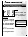
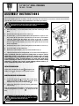
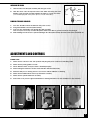
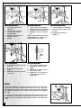
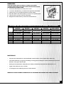
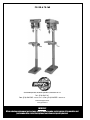
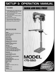
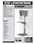
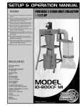
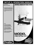
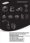
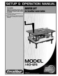
Rotating, 45° tilting, crank-operated
work-table with quick release clamp.
Large front mounted stop switch with
lock-out safety feature to prevent
unwanted or unintentional start-up.
Adjustable spindle tension return spring.
Built-in lamp illuminates the drilling area.
Spindle is supported by high quality ball
bearings.
Cast iron pulleys reduce vibration.
Industrial 1/2 HP motor.
Heavy-duty positive depth stop for quick
adjustment.
5/8” drill chuck.
SWING
13 3⁄8’’ (340 mm) - #75-150
16’’ (406 mm) - #75-160
DRILLING CAPACITY
5⁄ ” (16 mm)
8
CHUCK SIZE
5⁄ ” (16 mm)
8
SPINDLE TRAVEL
3 1⁄8” (80 mm)
SPINDLE DISTANCE TO TABLE
30 3⁄4” (781 mm) - #75-150
30 5⁄16” (770 mm) - #75-160
SPINDLE DISTANCE TO BASE
48” (1219 mm) - #75-150
47 11⁄16” (1212mm) - #75-160
TABLE SIZE
11 3⁄8” (289 mm) - #75-150
10 1⁄2” (268 mm) - #75-160
COLUMN DIAMETER
2 7⁄8” (73 mm)
NUMBER OF SPEEDS
12
SPINDLE SPEEDS
280-3000 RPM
SPINDLE TAPER
MT 2
OVERALL HEIGHT
62” (1575 mm)
BASE SIZE
10 1⁄4” x 17
10 7⁄8” x 19
1⁄ ” - #75-150
4
3⁄ ” - #75-160
16
MOTOR
1⁄ HP, 110 V, 8 A
2
WEIGHT
121 LBS (55 kg) - #75-150
134 LBS (61 kg) - #75-160
VERSION 2 - AUGUST 07/12
© Copyright General® International 08/2012
GENERAL® INTERNATIONAL
8360 Champ-d’Eau, Montreal (Quebec) Canada H1P 1Y3
Telephone (514) 326-1161 • Fax (514) 326-5555 • www.general.ca
THANK YOU for choosing this General
International model 75-150/75-160 drill
press. This drill has been carefully tested and inspected before shipment and if properly used
and maintained, will provide you with years of reliable service. To ensure optimum performance and trouble-free operation, and to get the most from your investment, please take the
time to read this manual before assembling, installing and operating the unit.
®
The manual’s purpose is to familiarize you with the safe operation, basic function, and features
of this drill as well as the set-up, maintenance and identification of its parts and components.
This manual is not intended as a substitute for formal woodworking instruction, nor to offer the
user instruction in the craft of woodworking. If you are not sure about the safety of performing
a certain operation or procedure, do not proceed until you can confirm, from knowledgeable
and qualified sources, that it is safe to do so.
Once you’ve read through these instructions, keep this manual handy for future reference.
Disclaimer: The information and specifications in this
manual pertain to the unit as it was supplied from the
factory at the time of printing. Because we are committed to making constant improvements, General®
International reserves the right to make changes to
components, parts or features of this unit as deemed
necessary, without prior notice and without obligation to
install any such changes on previously delivered units.
Reasonable care is taken at the factory to ensure that
the specifications and information in this manual corres-
ponds with that of the unit with which it was supplied.
However, special orders and “after factory” modifications may render some or all information in this manual
inapplicable to your machine. Further, as several generations of this model of drill and several versions of this
manual may be in circulation, if you own an earlier or
later version of this unit, this manual may not depict your
tool exactly. If you have any doubts or questions
contact your retailer or our support line with the model
number of your unit for clarification.
GENERAL® & GENERAL® INTERNATIONAL WARRANTY
All component parts of General®, General® International and Excalibur by General
International ® products are carefully inspected during all stages of production and each unit
is thoroughly inspected upon completion of assembly.
Limited Lifetime Warranty
Because of our commitment to quality and customer satisfaction, General® and General®
International agree to repair or replace any part or component which upon examination,
proves to be defective in either workmanship or material to the original purchaser for the life
of the tool. However, the Limited Lifetime Warranty does not cover any product used for professionnal or commercial production purposes nor for industrial or educational applications.
Such cases are covered by our Standard 2-year Limited Warranty only. The Limited Lifetime
Warranty is also subject to the “Conditions and Exceptions” as listed below.
Standard 2-Year Limited Warranty
All products not covered by our lifetime warranty including products used in commercial,
industrial and educational applications are warranted for a period of 2 years (24 months) from
the date of purchase. General® and General® International agree to repair or replace any
part or component which upon examination, proves to be defective in either workmanship or
material to the original purchaser during this 2-year warranty period, subject to the “conditions
and exceptions” as listed below.
To file a Claim
To file a claim under our Standard 2-year Limited Warranty or under our Limited Lifetime
Warranty, all defective parts, components or machinery must be returned freight or postage
prepaid to General® International, or to a nearby distributor, repair center or other location
designated by General® International. For further details call our service department at 1-888949-1161 or your local distributor for assistance when filing your claim.
Along with the return of the product being claimed for warranty, a copy of the original proof
of purchase and a “letter of claim” must be included (a warranty claim form can also be used
and can be obtained, upon request, from General® International or an authorized distributor)
clearly stating the model and serial number of the unit (if applicable) and including an explanation of the complaint or presumed defect in material or workmanship.
CONDITIONS AND EXCEPTIONS:
This coverage is extended to the original purchaser only. Prior warranty registration is not
required but documented proof of purchase i.e. a copy of original sales invoice or receipt
showing the date and location of the purchase as well as the purchase price paid, must be
provided at the time of claim.
Warranty does not include failures, breakage or defects deemed after inspection by General®
or General® International to have been directly or indirectly caused by or resulting from;
improper use, or lack of or improper maintenance, misuse or abuse, negligence, accidents,
damage in handling or transport, or normal wear and tear of any generally considered consumable parts or components.
Repairs made without the written consent of General® Internationallwill void all warranty.
RULES FOR SAFE OPERATION
To help ensure safe operation, please take a moment to learn the machine’s applications and limitations, as well as potential hazards. General® International disclaims any real or implied warranty and holds itself harmless for any injury that
may result from improper use of its equipment.
1. Do not operate the drill press when tired, distracted, or
under the effects of drugs, alcohol or any medication
that impairs reflexes or alertness.
2. The working area should be well lit, clean and free of
debris.
3. Keep children and visitors at a safe distance when the
drill press is in operation; do not permit them to operate the drill press.
4. Childproof and tamper proof your shop and all
machinery with locks, master electrical switches and
switch keys, to prevent unauthorized or unsupervised
use.
5. Stay alert! Give your work your undivided attention.
Even a momentary distraction can lead to serious
injury.
6. Fine particulate dust is a carcinogen that can be hazardous to health. Work in a well-ventilated area and
whenever possible use a dust collector and wear eye,
ear and respiratory protection devices.
7. Do not wear loose clothing, gloves, bracelets, necklaces or other jewelry while the drill press is in operation.
8. Be sure that adjusting wrenches, tools, drinks and
other clutter are removed from the machine and/or
the table surface before operating.
9. Keep hands well away from the drill bit and all moving
parts. Use a hold-down or clamp to secure the stock,
and use a brush, not hands, to clear away chips and
dust.
10. Be sure that the drill bit is securely installed in the
chuck before operation.
11. Be sure the drill bit has gained full operating speed
before beginning to drill.
12. Always use a clean, properly sharpened bit. Dirty or
dull bits are unsafe and can lead to accidents.
13. Use suitable work piece support if the work piece does
not have a flat surface.
14. Do not push or force the bit into the stock. The drill will
perform better and more safely when working at the
rate feed for which it was designed.
15. Avoid working from awkward or off balance positions.
Do not overreach and keep both feet on floor.
16. Keep guards in place and in working order. If a guard
must be removed for maintenance or cleaning be
sure it is properly re-attached before using the tool
again.
17. Never leave the machine unattended while it is running or with the power on.
18. Use of parts and accessories NOT recommended by
GENERAL® INTERNATIONAL may result in equipment
malfunction or risk of injury.
19. Never stand on machinery. Serious injury could result
if the tool is tipped over or if the drill bit is unintentionally contacted.
20. Always disconnect the tool from the power source
before servicing or changing accessories such as bits,
or before performing any maintenance, cleaning, or if
the machine will be left unattended.
21. Make sure that the switch is in the “OFF” position before
plugging in the power cord.
22. Make sure the tool is properly grounded. If equipped
with a 3-prong plug, it should be used with a threepole receptacle. Never remove the third prong.
23. Do not use this drill press for other than its intended
use. If used for other purposes, GENERAL® INTERNATIONAL disclaims any real implied warranty and holds
itself harmless for any injury, which may result from
that use.
ELECTRICAL REQUIREMENTS
BEFORE CONNECTING THE MACHINE TO THE POWER SOURCE, VERIFY THAT THE VOLTAGE OF YOUR POWER SUPPLY CORRESPONDS
WITH THE VOLTAGE SPECIFIED ON THE MOTOR I.D. NAMEPLATE. A POWER SOURCE WITH GREATER VOLTAGE THAN NEEDED CAN
RESULT IN SERIOUS INJURY TO THE USER AS WELL AS DAMAGE TO THE MACHINE. IF IN DOUBT, CONTACT A QUALIFIED ELECTRICIAN
BEFORE CONNECTING TO THE POWER SOURCE.
THIS TOOL IS FOR INDOOR USE ONLY. DO NOT EXPOSE TO RAIN OR USE IN WET OR DAMP LOCATIONS.
EXTENSION CORDS
If you find it necessary to use an extension cord with your
machine, use only 3-wire extension cords that have 3prong grounding plug and a matching 3-pole receptacle that accepts the tool’s plug. Repair or replace a
damaged extension cord or plug immediately.
Make sure the cord rating is suitable for the amperage
listed on the motor I.D. plate. An undersized cord will
cause a drop in line voltage resulting in loss of power
and overheating. The accompanying chart shows the
correct size extension cord to be used based on cord
length and motor I.D. plate amp rating. If in doubt, use
the next heavier gauge. The smaller the number, the
heavier the gauge.
GROUNDING INSTRUCTIONS
In the event of an electrical malfunction or short circuit,
grounding reduces the risk of electric shock. The motor
of this machine is wired for 110V single phase operation
and is equipped with a 3-conductor cord and a 3prong grounding plug
to fit a grounded type receptacle . Do not remove the 3rd prong (grounding pin)
to make it fit into an old 2-hole wall socket or extension
cord. If an adaptor plug is used , it must be attached
to the metal screw of the receptacle.
Note: The use of an adaptor plug is illegal in some
areas. Check your local codes. If you have any doubts
or if the supplied plug does not correspond to your electrical outlet, consult a qualified eletrician before proceeding.
TABLE - MINIMUM GAUGE FOR CORD
TOTAL LENGTH OF CORD IN FEET
110
VOLTS
25
FEET
50 FEET 100 FEET
AMPERE
RATING 220 VOLTS 50 FEET 100 FEET 200 FEET
150 FEET
300 FEET
AWG
------->
6 TO 10 ------->
10 TO 12 ------->
12 TO 16 ------->
<5
18
16
16
14
18
16
14
12
16
16
14
12
14
12
* NR
* NR
* NR = Not Recommended
CIRCUIT CAPACITY
Make sure that the wires in your circuit are capable of
handling the amperage draw from your machine, as
well as any other machines that could be operating on
the same circuit. If you are unsure, consult a qualified
electrician. If the circuit breaker trips or the fuse blows
regularly, your machine may be operating on a circuit
that is close to its amperage draw capacity. However, if
an unusual amperage draw does not exist and a
power failure still occurs, contact a qualified technician
or our service department.
5
14” OR 16” DRILL PRESSES
75-150 • 75-160
A S S E M B LY I N S T R U C T I O N S
Before proceeding with the assembly, read the operating and maintenance instructions manual and familiarize
yourself with correct assembly, setup, maintenance and safety procedures.
TO AVOID RISK OF SERIOUS INJURY, MAKE SURE THE DRILL PRESS IS
INSTALLED ON A FLAT, SOLID AND STABLE SURFACE.
1.
Place the base (1) on a flat surface and screw the column (8), to the
base.
2.
Remove the rack ring (9) from the column (8).
3.
Insert the rack (11) into the table bracket and position the 2 pieces onto
the column at the same time. The bottom lip of the rack is pressed between the column and the flange. The top lip of the rack is similarly
secured with the replacement of the rack ring (9). Tighten the set screw in
the rack ring. Place the handle (10) on the worm gear and secure it with
the hex head bolt.
4.
Attach the head (2) to the column and tighten the head with the set screws (3).
5.
Secure the table onto the table arm.
6.
Attach the 3 feed handles, (4, 5 & 6), to the handle body (7).
7.
If desired, install a max. 60 watt light bulb (not included) for the worklight (12).
Once assembled, clean the protective coating from all surfaces (where
applicable) using a rag dipped in kerosene, mineral spirits or paint
thinner. (Dispose of potentially flammable solvent-soaked rags according
to manufacturer’s safety recommendations.) A putty knife, held flat to
avoid scratching the surface, may also be used to scrape off the coating
followed by clean-up with solvent. Avoid rubbing painted surfaces, as
many solvent-based products will remove paint.
INSTALL THE CHUCK GUARD
Fit the chuck guard onto the quill
and tighten the
Phillips screw
to secure the chuck guard in place.
ADJUSTING AND USING THE CHUCK GUARD
1.
Loosen the wing nuts
on both sides of the chuck
guard and slide the chuck guard extension down
along the two slots to the desired height .
2.
Tighten the wing nuts to lock the chuck guard exten
sion in place.
Note: To facilitate drill bit installation / removal, flip the spring
loaded chuck guard up as shown in
to keep it out of the
way.
TO PREVENT THE RISK OF SERIOUS INJURIES, ALWAYS
COVER THE CHUCK AND DRILL BIT WITH THE CHUCK
GUARD WHEN USING THE DRILL PRESS.
6
REAR VIEW
INSTALLING THE CHUCK
1.
Slide the arbor into the quill assembly, flat end goes in first.
2.
Slide the chuck onto the tapered end of the arbor and using the feed
handle, lower the quill assembly against the table to secure the chuck.
(To avoid damaging the chuck place a piece of wood on the table.)
Quill
Assembly
Tool
Arbor
Chuck
REMOVING THE CHUCK AND ARBOR
1.
Turn “OFF” and disconnect the drill from the power source.
2.
Using feed handle, lower the quill assembly.
3.
Insert tool into, and all the way through the quill assembly.
Note: It may be necessary to rotate the quill in order to be able to get the tool all the way through.
4.
While holding onto the chuck to prevent damage, raise the quill assembly. The arbor and chuck should fall out.
ADJUSTMENTS AND CONTROLS
POWER “ON”
1.
Make sure the switch is in the “OFF” position and plug the power cord into a matching outlet.
2.
Make sure the pulley guard is closed.
3.
Check that the chuck or keyless chuck is installed properly.
4.
When turning the machine “ON” be aware that the shaft will rotate freely.
5.
When the drill press is running check to see if it runs without vibration or shaking.
6.
Make sure the table bracket moves up and down smoothly.
7.
Make sure the spindle shaft turns smoothly.
8.
Unlock the cover, press the green start button for starting machine. Press the red button to stop machine.
WORK-LIGHT SWITCH
POWER ON
POWER OFF
7
ADJUSTING TABLE HEIGHT
TABLE SWING ADJUSTMENT
TABLE ROTATION ADJUSTMENT
1.
1.
Loosen column lock handle (1).
1.
Loosen the table lock handle (3).
2.
2.
Turn the crank handle (2)
until the table is at the
desired height.
Swing the table arm bracket and
the table to the desired position.
Rotate the table to the desired
position.
3.
Retighten column lock handle
(1).
3.
Retighten the table lock
handle (3).
Retighten the column lock
handle (1) before
starting.
When working with taller work pieces
swing the table 180° out of the way
and use the base as a table.
2.
3.
Loosen the column lock
handle (1).
TABLE TILT ADJUSTMENT
DEPTH STOP ADJUSTMENT
1.
Loosen the pivot bolt (4) and set
screw (5).
1.
2.
Tilt the table to the desired
angle.
Set the bottom edge of nut #1
even with the desired depth
setting.
2.
3.
Retighten the pivot bolt (4) and
set screw (5).
Tighten nut #2 against nut #1 to
secure it in position.
3.
Depth stop is now set and will
provide repetitive holes of
equal depth.
DRILLING
Always use hold-downs or clamps to secure the workpiece. The workpiece
should never be held only by hand. Take care to use clean, sharp bits.
Damaged or broken bits could result in serious injury. When drilling flat
work, place the worpiece on a wooden base and clamp it down against
the table.
For working in wood, machine spur bits are generally preferred. Do not
use hand bits, which have a screw tip. At drill press speeds these bits rotate
into the workpiece so rapidly that they lift the workpiece off the table and
swirl it.
8
CHANGING SPEEDS
MAKE SURE THE DRILL PRESS HAS COME TO A COMPLETE STOP BEFORE
CHANGING SPEEDS. REFER TO THE SPINDLE SPEED SELECTION CHART LOCATED
ON THE INSIDE OF THE SPINDLE COVER.
1.
Disconnect the drill press from the power source.
2.
Loosen the slide bar bolt (1) located on the right side of the head.
3.
Pull the motor (2) in towards the head to loosen the belts.
4.
Relocates belts to the desired pulleys to select a new spindle speed.
5.
Push the motor (2) back, away from the head.
6.
Retighten the slide bar bolt (1) and check the belt tension.
THE FOLLOWING TABLE CAN BE USED AS A GUIDLINE FOR SELECTING SPEEDS BASED ON BIT SIZE & BIT MATERIAL.
BIT SIZE
CAST STEEL
BIT MATERIAL
CAST IRON
TOOL STEEL
MILD STEEL
ALUM. & COPPER
100 FT/MIN (30 M/MIN)
200 FT/MIN (60 M/MIN)
CUTTING SPEED
40 FT/MIN (12 M/MIN)
60 FT/MIN (18 M/MIN)
1/16” (2 mm)
1910 - 2445 RPM
2865 - 3665 RPM
3820 - 4890 RPM
4775 - 6110 RPM
9550 - 12225 RPM
1/8” (3 mm)
1220 -1275 RPM
1835 -1910 RPM
2445 - 2545 RPM
3055 - 3185 RPM
6110 - 6365 RPM
3/16” (5 mm)
765 - 815 RPM
1145 - 1220 RPM
1530 - 1630 RPM
1910 - 2035 RPM
3820 - 4075 RPM
1/4” (6 mm)
610 RPM
915 - 955 RPM
1220 - 1275 RPM
1530 - 1590 RPM
3055 - 3180 RPM
5/16” (8 mm)
480 - 490 RPM
715 - 735 RPM
955 - 980 RPM
1195 - 1220 RPM
2390 - 2445 RPM
3/8” (10 mm)
380 - 405 RPM
570 - 610 RPM
765 - 815 RPM
955 - 1020 RPM
1910 - 2035 RPM
7/16” (11 mm)
350 RPM
520 - 525 RPM
700 RPM M/MIN)
870 RPM
1740 - 1745 RPM
1/2” (13 mm)
300 - 305 RPM
440- 460 RPM
590 - 610 RPM
735 - 765 RPM
1470 - 1530 RPM
DIAMETER
80 FT/MIN (24 M/MIN)
REVOLUTIONS PER MINUTE
MAINTENANCE
•
Keep the unit clean and free of dust and debris. Painted surfaces can be wiped with a damp rag.
•
Periodically lubricate (oil or grease) all sliding or moving parts including the column and table tilt mechanisms,
brackets, worm gears and the quill.
•
Bearings in the quill and the V-belt pulley are sealed, permanently lubricated and maintenance free.
•
Lightly oil the slide bars every 2 months.
•
If cranking becomes difficult, grease the column bracket.
IMPORTANT: USE ONLY GENERAL INTERNATIONAL OR AUTHORIZED REPLACEMENT PARTS AND ACCESSORIES.
9
RECOMMENDED OPTIONAL ACCESSORIES
We offer a large variety of products to help you increase convenience, productivity, accuracy and safety when
using your drill press Here’s a small sampling of optional accessories available from your local General
International dealer.
For more information about our products, please visit our website at www.general.ca
25 PIECE - RUBBER DRUM
SANDING SET
#75-025
Turn your drill press into a mini
drum sander. Ideal for small
sanding jobs on curved or
odd shaped pieces. Kit
includes 5 different sized
drums: 1/2”, 3/4”, 1”, 1-1/2” &
2” plus 2 sets of 80 grit and 2
sets of 120 grit sanding sleeves
for each.
ABRASIVE SLEEVES
#70-030
10 piece replacement
abrasive sleeve set for
70-025. Includes 5 (one of
each size) 80 & 120 grit
sanding sleeves.
9” AUGER DRILL BIT SET
#70-105
DRILL PRESS TOOL TRAY
#70-125
Heavy duty carbon steel. Heattreated and precision sharpened for quick, accurate and
effortless cuts. Includes 6 bits sizes: 1/4”, 5/16”, 3/8”, 1/2”,
5/8”, 3/4” with 3/8” shank, in a
conve-nient carrying case.
Can be installed on
most drill press columns.
Made from durable plastic
with a metal swivel rod.
12” X 24” (305 X 610 MM)
UNIVERSAL DRILL PRESS TABLE
#70-135
17” X 32” (432 X 813 MM)
UNIVERSAL DRILL PRESS TABLE
#70-140
Adds versatility to your drill press
and repeatable accuracy to
your work. Includes: 3” tall 2-pc.
Full length fence with t-slot and
stop, 2-1/2” dust port connection,
parallel t-slots in table and 2
workpiece holdowns. Mounts to
all drill tables with mounting
holes.
DRILL PRESS CHUCK • Prevents unintentional user con
tact with the chuck and bit dur
GUARD - 70-155
ing operations.
• Contains wood chips, shavings
or other debris for safer
drilling.
• Designed to meet the most strin
gent industrial and educa
tional safety requirements.
• Sturdy cast aluminum body and
pact resistant windows.
• Spring loaded flip-up design,
allows for quick drill bit
changes without interference.
9” VISE-CLAMP
#70-130
DRILL PRESS VISES
#95-140/95-150/95-160
Adjustable lock-in clamping
pressure and 360 degree rotation; a must for all safety conscious woodworkers. Includes
two 1/2” t-bolts to mount to
any drill table with 9/16” (or
wider)mounting holes.
Hold down slots along both
sides. High tensile iron casting construction for maximum durability. One-piece
cast-iron axial sleeve and
movable jaws. Fast action,
“Acme” type screw threads.
95-140 (4”) / 95-150 (5”) / 95160 (6”)
10
PARTS LIST
75-150
PART N0.
DESCRIPTION
QTY
75150-01
75150-02
75150-03
75150-04
75150-05
75150-06
75150-07
75150-07-1
75150-08
75150-09
75150-10
75150-11
75150-12
75150-12-1
75150-13
75150-14
75150-15
75150-16
75150-17
75150-18N
75150-19
75150-20
75150-21
75150-22N
75150-23
75150-24N
75150-25
75150-26
75150-26-1
75150-26-2
75150-27
75150-28
75150-28-1
75150-29
75150-30
75150-31
75150-32
75150-32-1
75150-33
75150-34
75150-35N
75150-36
75150-37
75150-38N
75150-39
75150-40
75150-40-1
BASE
WASHER
BOLT
BASE FLANGE
SCREW
CRANK SLEEVE HANDLE
TABLE BRACKET
TILT SCALE
GEAR SHAFT
HELICAL GEAR
ELEVATING WORM
CLAMP BOLT
TABLE ARM BRACKET
POINTER
SET SCREW
CLAMP BOLT
WASHER
BOLT
TABLE
RACK
COLUMN 73 X 1160
SCREW
RACK COLLAR
FEED HANDLE
HANDLE KNOB
PINION SHAFT
SLEEVE
HEAD
SET SCREW
RUBBER BUSHING
SET SCREW
BELT TENSION ADJUSTMENT ROD
SPRING
SCREW
SCREW
LAMP FRAME
LAMP HOLDER
NUT
NUT
SPRING & CAP
SWITCH BOX
SCREW
LIGHT SWITCH
ON/OFF SWITCH
SCREW
ELECTRICAL CORD
MOTOR CORD
1
4
4
1
1
1
1
1
1
1
1
1
1
1
1
1
1
1
1
1
1
1
1
3
3
1
1
1
1
2
1
1
1
1
4
2
1
1
1
1
1
3
1
1
1
1
1
11
PARTS LIST 75-150
12
PART N0.
DESCRIPTION
QTY
75150-41
75150-42
75150-43
75150-44
75150-45
75150-46
75150-47
75150-48
75150-49
75150-49-1
75150-50
75150-51
75150-52
75150-53
75150-54
75150-55
75150-56
75150-57
75150-58
75150-59
75150-60
75150-61
75150-62
75150-63
75150-64
75150-65
75150-66
75150-67
75150-68
75150-69
75150-70
75150-71
75150-72
75150-73
75150-74
75150-75
75150-76
75150-77
75150-78
75150-79
75150-80
75150-81
75150-82
75150-83
75150-84
75150-85
75150-86
75150-87
75150-88
75150-89
75150-90
75150-91
75150-92
SNAP RING
DRIVER INSERT
BEARING
SNAP RING
BEARING
QUILL GASKET
QUILL
BEARING
SUPPORT / CLAMP SEAT DEPTH STOP
NUT
SCREW
SPINDLE
DRIFT KEY
ARBOR
CHUCK
KEY
BOLT
MOTOR
SCREW
CAPACITOR COVER
CAPACITOR
PULLEY GUARD
MOTOR PULLEY
SET SCREW
SNAP RING
SNAP RING
BEARING
MIDDLE PULLEY
V-BELT
V-BELT
KNOB (SEE ITEM #75200-03)
SCREW
SHAFT ASSEMBLY
NUT
SPINDLE PULLEY
SCREW
CORD CLAMP
ELECTRICAL CORD / LAMP
SCREW
SCREW
KEY HOLDER
WASHER
NUT
SCREW
DEPTH STOP ROD
NUT
DEPTH STOP SUPPORT
CHUCK GUARD - ITEM #70-115A
COLUMN PLATE
WASHER
SPRING
WASHER
CAP SCREW
1
1
1
1
1
1
1
1
1
1
1
1
1
1
1
1
2
1
2
1
1
1
1
1
1
1
1
1
1
1
1
1
1
1
1
1
1
1
1
1
1
1
1
1
1
2
1
1
1
1
1
1
1
DIAGRAM 75-150
64
65
66
EA
40
68
67
SID
69
62
63
80
85(2)
78
77(2) 79 81
75
76 40-1
61
72
84
60
83
86
82
71
59
32-1
73
33
34
74
40-1
30(2)
31
32
EA
SID
58(2)
57
29(4)
56(2)
28-1
28
27
40
36(3)
26-1
35N26-2
26
41
39(3)
37
25
23(3)
24N
42
44
45
38N
43
22N(3)
21
46
43
92
20
47
89
41
90 91
48
51
19
50
18N
52
49
53
10
49-1
11
87
54
7-1
9
12-1
55
8
12
88
17
7
6
4
16
5
13
15
14
3(4)
2(4)
1
13
PARTS LIST
75-160
14
PART N0.
DESCRIPTION
75160-01
75160-02
75160-03
75160-04
75160-05
75160-06
75160-07
75160-07-1
75160-08
75160-09
75160-10
75160-11
75160-12
75160-13
75160-14
75160-15
75160-16
75160-17
75160-18N
75160-19
75160-20
75160-21
75160-22N
75160-23
75160-24N
75160-25
75160-26
75160-26-1
75160-26-2
75160-27
75160-28
75160-28-1
75160-29
75160-30
75160-31
75160-32-1
75160-33
75160-34
75160-35N
75160-36
75160-37
75160-38N
75160-39
75160-40
75160-40-1
75160-41
75160-42
BASE
WASHER
BOLT
BASE FLANGE
SCREW
CRANK SLEEVE HANDLE
TABLE BRACKET
TILT SCALE
GEAR SHAFT
HELICAL GEAR
ELEVATING WORM
CLAMP BOLT
TABLE ARM BRACKET
SET SCREW
CLAMP BOLT
WASHER
BOLT
TABLE
RACK
COLUMN 73 X 1160
SCREW
RACK COLLAR
FEED HANDLE
HANDLE KNOB
PINION SHAFT
SLEEVE
HEAD
SET SCREW
RUBBER BUSHING
SET SCREW
BELT TENSION ADJUSTMENT ROD
SPRING
SCREW
SCREW
LAMP HOLDER
NUT
NUT
SPRING & CAP
SWITCH BOX
SCREW
LIGHT SWTICH
ON/OFF SWITCH
SCREW
ELECTRICAL CORD
MOTOR CORD
SNAP RING
DRIVER INSERT
QTY
1
4
4
1
1
1
1
1
1
1
1
1
1
1
1
1
1
1
1
1
1
1
3
3
1
1
1
2
1
1
1
1
4
2
1
1
1
1
1
3
1
1
1
1
1
1
1
PARTS LIST
75-160
PART N0.
DESCRIPTION
QTY
75160-43
75160-44
75160-45
75160-46
75160-47
75160-48
75160-49
75160-49-1
75160-50
75160-51
75160-52
75160-53
75160-54
75160-55
75160-56
75160-57
75160-58
75160-59
75160-60
75160-61
75160-62
75160-63
75160-64
75160-65
75160-66
75160-67
75160-68
75160-69
75160-70
75160-71
75160-72
75160-73
75160-74
75160-75
75160-76
75160-77
75160-78
75160-79
75160-80
75160-81
75160-82
75160-83
75160-84
75160-85
75160-86
75160-87
75160-88
75160-89
75160-90
75160-91
75160-92
BEARING
SNAP RING
BEARING
QUILL GASKET
QUILL
BEARING
SUPPORT / CLAMP SEAT DEPTH STOP
NUT
SCREW
SPINDLE
DRIFT KEY
ARBOR
CHUCK
KEY
BOLT
MOTOR
SCREW
CAPACITOR COVER
CAPACITOR
PULLEY GUARD
MOTOR PULLEY
SET SCREW
SNAP RING
SNAP RING
BEARING
MIDDLE PULLEY
V-BELT
V-BELT
KNOB (SEE ITEM #75200-03)
SCREW
SHAFT ASSEMBLY
NUT
SPINDLE PULLEY
SCREW
CORD CLAMP
ELECTRICAL CORD / LAMP
SCREW
SCREW
KEY HOLDER
WASHER
NUT
SET SCREW
DEPTH STOP ROD
NUT
DEPTH STOP SUPPORT
CHUCK GUARD - ITEM #70-115A
COLUMN PLATE
WASHER
SPRING
WASHER
CAP SCREW
1
1
1
1
1
1
1
1
1
1
1
1
1
1
2
1
2
1
1
1
1
1
1
1
1
1
1
1
1
1
1
1
1
1
1
1
1
1
1
1
1
1
1
2
1
1
1
1
1
1
1
15
DIAGRAM 75-160
64
65
66
68
67
69
62
63
40
80
85(2)
61
72
75
76 40-1
78
81
77(2) 79
82
60
84
83
86
71
32-1
73
33
74
40
41
34
36(3)
E
SID
31
32
A
58(2)
30(2)
29(4)
28-1
35N
26-2
28
26-1
26
25
44
45
38N
43
43
24N
22N(3)
92
20
47
89
90 91
41
48
19
50
52
87
23(3)
21
46
51
53
18 N
49
49-1
10
11
54
7-1
55
9
12-1
12
88
17
16
13
15
4
8
7
6
5
14
3(4)
2(4)
1
16
57
56(2)
27
39(3)
37
42
59
40-1
NOTES:
17
75-150 & 75-160
8360 Champ-d’Eau, Montreal (Quebec) Canada H1P 1Y3
Fax: (514) 326-5565 -
Tel.: (514) 326-1161
Fax: (514) 326-5555 -
Parts & Service /
Order Desk
[email protected]
www.general.ca
IMPORTANT
When ordering replacement parts, always give the model number, serial number of the machine and
part number. Also a brief description of each item and quantity desired.