1
OPERATOR’S MANUAL
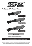
14" Band Saw
Model # 3914
2
Table of Contents
Technical data ..................................................................................................................................2
General safety rules..........................................................................................................................4
Specific safety rules for band saws ..................................................................................................6
Electrical information ......................................................................................................................7
Know your band saw .......................................................................................................................9
Assembly and adjustments .............................................................................................................10
Operation........................................................................................................................................20
Maintenance ...................................................................................................................................21
Exploded view and parts list ..........................................................................................................22
Warranty ........................................................................................................................................27
Technical Data
14inch Band Saw
Model:
Motor:
Motor speed:
Blade speed:
Blade length:
Blade width range:
Depth of throat at 90°:
Maximum depth of cut at 90°:
Maximum depth of cut at 45°:
Table size:
Table tilt:
Wheel diameter:
Overall dimensions:
3914
120 V, 60 Hz, 9.5 A
1725 RPM (no load)
1445/3150 FPM
100-3/4"
1/8" to 3/4"
13-1/2"
9"
6"
15-3/4" x 21-1/2"
0° to 45°
13-3/4"
33" x 20" x 68"
3
General safety rules
Safety is a combination of common sense, staying alert and knowing how your band saw works.
SAVE THESE SAFETY INSTRUCTIONS.
WARNING: To avoid mistakes that could cause serious injury, do not plug in the
band saw until the following steps have been read and understood.
1. READ and become familiar with this entire instruction manual. LEARN the tool’s
applications, limitations, and possible hazards.
2. AVOID DANGEROUS CONDITIONS. Do not use power tools in wet/damp areas or expose
them to rain. Keep work areas well lit.
3. DO NOT use power tools in the presence of flammable liquids or gases.
4. ALWAYS keep your work area clean, uncluttered, and well lit. DO NOT work on floor
surfaces that are slippery with sawdust or wax.
5. KEEP BYSTANDERS AT A SAFE DISTANCE from the work area, especially when the
tool is operating. NEVER allow children or pets near the tool.
6. DO NOT FORCE THE TOOL to do a job for which it was not designed.
7. DRESS FOR SAFETY. Do not wear loose clothing, gloves, neckties, or jewelry (rings,
watches, etc.) when operating the tool. Inappropriate clothing and items can get caught in
moving parts and draw you in. ALWAYS wear non-slip footwear and tie back long hair.
8. WEAR A FACE MASK OR DUST MASK as the sawing operation produces dust.
WARNING: Dust generated from certain materials can be hazardous to your health.
Always operate the band saw in a well-ventilated area and provide for proper dust
removal. Use dust collection systems whenever possible.
9. ALpower cord plug from the electrical outlet whaking adjustments,
changing parts, cleaning, or working on the tool.
10. KEEP GUARDS IN PLACE AND IN WORKING ORDER.
11. AVOID ACCIDENTAL START-UPS. Make sure the power switch is in the OFF position
before plugging in the power cord.
12. REMOVE ADJUSTMENT TOOLS. Always make sure all adjustment tools are removed
from the saw before turning it on.
4
13. NEVER LEAVE A RUNNING TOOL UNATTENDED. Turn the power switch to OFF. Do
not leave the tool until it has come to a complete stop.
14. NEVER STAND ON A TOOL. Serious injury could result if the tool tips or is accidentally
hit. DO NOT store anything above or near the tool.
15. DO NOT OVERREACH. Keep proper footing and balance at all times. Wear oilresistantrubber-soled footwear. Keep the floor clear of oil, scrap, and other debris.
16. MAINTAIN TOOLS PROPERLY. ALWAYS keep tools clean and in good working order.
Follow instructions for lubricating and changing accessories.
17. CHECK FOR DAMAGED PARTS. Check for alignment of moving parts, jamming,
breakage, improper mounting, or any other conditions that may affect the tool’s operation.
Any part that is damaged should be properly repaired or replaced before use.
18. MAKE THE WORKSHOP CHILDPROOF. Use padlocks and master switches and
ALWAYS remove starter keys.
19. DO NOT operate the tool if you are under the influence of drugs, alcohol, or medication that
could affect your ability to use the tool properly.
20. USE SAFETY GOGGLES AT ALL TIMES that comply with ANSI Z87.1. Normal safety
glasses only have impact resistant lenses and are not designed for safety. Wear a face or dust
mask when working in a dusty environment. Use ear protection such as plugs or muffs during
extended periods of operation.
5
Specific safety rules for band saws
1. To avoid injury from unexpected movement, make sure the saw is on a firm, level surfaceand
secured properly to prevent rocking. Make sure there is adequate space for operations. Bolt
the saw to a support surface to prevent slipping or sliding during operation.
2. Turn off and unplug the saw before moving it.
3. Use the correct size and style of blade.
4. Make sure the blade teeth point down and toward the table.
5. Blade guide, supports, bearings, and blade tension must be properly adjusted to avoid
accidental blade contact and to minimize blade breakage. To maximize blade support, always
adjust the upper blade guide and blade guard so that it barely clears the workpiece.
6. Table TILT lock handle should be tight.
7. Use extra caution with very large, very small, or awkwardly shapedworkpieces.
8. Use extra supports to prevent workpieces from sliding off the tabletop.
9. Workpieces should be secured so they don’t twist, rock, or slip while being cut.
10. Plan intricate or small work carefully to avoid pinching the blade. Avoid awkward operations
and hand positions to prevent accidental contact with the blade.
11. Small pieces should be secured with clamps or fixtures. Do not hold small pieces with your
hand since your fingers may go under the blade guard.
12. Support round work properly (use a V block or press it against the miter gauge) to prevent
the piece from rolling and the blade from biting.
13. Cut only one workpiece at a time. Make sure the table is clear of everything except the
workpiece and its guides before turning on the saw.
14. Always watch the saw run before each use. If there is excessive vibration or unusual noise,
stop immediately. Turn the saw off. Unplug it immediately. Do not start the saw again until
the problem has been located and corrected.
15. To free any jammed material, turn the switch off. Remove the switch key and unplug the saw.
Wait for all moving parts to stop before removing the jammed material.
6
16. Don’t leave the work area until all moving parts have stopped. Shut off the power to master
switches. Remove the switch key from the band saw and store it in a safe place away from
children. Childproof the workshop!
Electrical information
Grounding Instructions
IN THE EVENT OF A MALFUNCTION OR BREAKDOWN, grounding provides the path of
least resistance for electric current and reduces the risk of electric shock. This tool is equipped
with an electric cord that has an equipment-grounding conductor and a grounding plug. The plug
MUST be plugged into a matching outlet that is properly installed and grounded in accordance
with ALL local codes and ordinances.
DO NOT MODIFY THE PLUG PROVIDED. If it does not fit the outlet, have the proper outlet
installed by an electrician.
IMPROPER CONNECTION of the equipment grounding conductor can result in electric shock.
The conductor with the green insulation (with or without yellow stripes) is the equipmentgrounding conductor. DO NOT connect the equipment-grounding conductor to a live terminal if
repair/replacement of the electric cord/plug is necessary.
CHECK with a licensed electrician or service personnel if you do not completely understand the
grounding instructions or if the tool is properly grounded.
USE ONLY THREE-WIRE EXTENSION CORDS with three-prong plugs and three-prong
outlets as shown in Fig. A. Repair or replace a damaged or worn cord immediately.
CAUTION: In all cases, make certain the outlet in question is properly grounded. If you are not
sure, have a licensed electrician check the outlet.
WARNING: This saw is for indoor use only. Do not expose to rain or use in damp
locations.
7
Guidelines for Using Extension Cords
Make sure your extension cord is in good condition. When using an extension cord, be sure to
use one heavy enough to carry the current your product will draw. An undersized cord will cause
a drop in line voltage resulting in loss of power and overheating. The table below shows the
correct size to be used according to cord length and nameplate ampere rating. When in doubt, use
a smaller-numbered gauge (the smaller the gauge number, the heavier the cord).
Minimum Gauge for Extension Cords (AWG)
(when using 120 V only)
25 Feet
18 Gauge
Total Length of Cord in feet
50 Feet
100 Feet
16 Gauge
14 Gauge
150 Feet
12 Gauge
Be sure your extension cord is properly wired and in good condition. Always replace a damaged
extension cord or have it repaired by a qualified person before using it.
Protect your extension cords from sharp objects, excessive heat and damp or wet areas.
Use a separate electrical circuit for your tools. This circuit must not be less than a #12 wire and
should be protected with a 15 A time-delayed fuse. Before connecting the motor to the power
line, make sure the switch is in the OFF position and the electric current is rated the same as the
current stamped on the motor nameplate. Running at a lower voltage will damage the motor.
WARNING: This tool must be grounded while in use to protect the operator from
electrical shock.
8
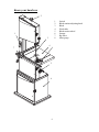
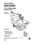
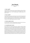
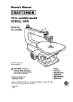
Know your band saw
2
1
2
3
4
5
6
7
8
1
3
7
4
8
5
6
9
Switch
Blade-tension-adjusting knob
Blade
Work table
Blade tension wheel
Storage
Rip fence
Miter gauge
WARNING: For your own safety, read the instruction manual before operating the
band saw.
1.
2.
3.
4.
5.
6.
Wear eye protection.
Do not wear gloves, neckties, jewelry, or loose clothing.
Make sure the saw is properly secured on a firm, level surface.
Use only the recommended accessories.
Use extra caution with very large, very small, or awkwardly shapedworkpieces.
Keep hands away from the blade at all times to prevent accidental injury.
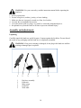
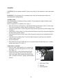
Assembly and adjustments
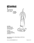
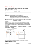
Unpacking
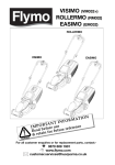
Carefully unpack the band saw and all its parts. Compare against the list below. Do not discard
the carton or any packaging until the band saw is completely assembled.
WARNING: If any part is missing or damaged, do not plug in the band saw until the
missing or damaged part is replaced.
1
2
3
1
2
3
4
5
Rip fence assembly
Push stick
Miter gauge
Guide rail
Work table
4
5
10
6
7
10
6
7
8
9
10
11
12
8
11
9
12
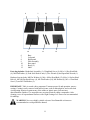
Base
Left panel
Right panel
Door assembly
Rear panel
Brace (2)
Shelf
Parts bag includes: Handwheel Assembly (1), WingKnob Screw (4), M6 x 16 Hex Head Bolt
(4), M6 FlatWasher (4), Push Stick Hook w/nut (1), Hex Wrench (1)and Open End Wrench (1).
Hardware bag includes: M8 Flat Washer (4), M6 x 16Hex Head Bolt (12), M6 x 16 Socket Head
Bolt (4), M6 x40 Flat Head Screw (4), M6 Flat Washer (24), M6 HexNut (8), M5 x 6 Pan Head
Screw (2) and M5 FlatWasher (2).
IMPORTANT: Table is coated with a protectant. Toensure proper fit and operation, remove
coating. Coatingis easily removed with mild solvents, such as mineralspirits, and a soft cloth.
Avoid getting solution on paint orany of the rubber or plastic parts. Solvents may
deterioratethese finishes. Use soap and water on paint, plasticor rubber components. After
cleaning, cover all exposedmetal surfaces with a light coating of oil. Paste wax isrecommended
for tabletop.
WARNING: Never use highly volatile solvents. Non-flammable solvents are
recommended to avoid possiblefire hazard.
11
Assembly
CAUTION: Do not attempt assembly if parts are missing.Use this manual to order replacement
parts.
WARNING: To avoid injury, do not attempt to run oruse this machine until all parts are
assembled and workingproperly.
Assembly stand
Note: Hand-tighten all hardware during assembly. Do notcompletely tighten hardware until
assembly is complete.
Refer to Exploded View and Parts List, Page 26.
1. Place base (Item 6) on flat surface. Attach right and left panels (Item 1 and 5) to base using
four socket head bolts, washers and hex nuts (Item 14, 10 and 13).
2. Attach rear panel (Item 3) to the side panels using four hex head bolts and flat washers (Item
10 and 11).
3. Attach the two braces (Item 2) to the top front and bottom front of the side panels using four
hex head bolts and flat washers.
4. Attach the shelf (Item 4) to the center of the side panels using four hex head bolts and flat
washers.
5. Attach the door assembly (Item 7) to the left panel using two pan head screws and flat
washers (Item 8 and 9).
6. Secure all hardware.
7. Place band saw on top of stand and secure in position using four flat head screws, washers,
and hex nuts (Item 12, 10 and 13).
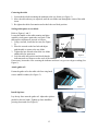
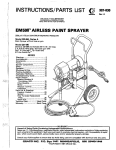
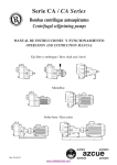
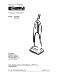
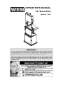
Attach table to trunnion
1. Place the table on the trunnion. Use caution when
passing the saw blade through the slot of the table
(See Figure 1).
2. Locate four M6 x 16 hex bolts and four M6 flat
washers from the bag of loose parts. Mount the
table to the upper table trunnion and install a bolt
with a washer in each hole. Tighten with adjustable
wrench.
1
2
3
Figure 1
1- Bolt Attach Table
2- Indicator
3- Adjusting Bolts
12
Centering the table
1. Loosen the hex bolts mounting the trunnion to the saw frame (see Figure 1).
2. Move the table sideways as required, until the saw blade runs through the center of the table
insert.
3. Re-tighten hex bolts for trunnion and recheck the saw blade position.
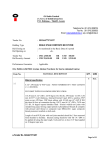
Setting table square to saw blade
Refer to Figures 1 and 2.
Loosen the handle on the table trunnion and place
asuitably sized square against the saw blade. If the
tablerequires adjustment, proceed as follows:
1. Using a wrench, loosen the hex nut (See Figure
Bolt
2).
2. Place the wrench on the hex bolt and adjust
until thetable is square to the saw blade.
3. Tighten the hex nut and recheck the saw blade
andthe table for squareness.
Figure 2
4. Lock the table into position and check that the
Nut
indicatorreads zero degrees on the scale of the trunnion.
If necessary, loosen the screw securing the indicator and reset it to give zero degree reading (See
Figure 1).
Attach guide rail
Fasten the guide rail to the table with four wing knob
screws andM8 washers (See Figure 3).
Wing knob screws
Figure 3
Install rip fence
Lay the rip fence onto the guide rail. Adjust the ripfence
parallel to the saw blade. Tighten rip fence handleby
pressing downward (See Figure 4).
Figure 4
13
Figure 5
Attach pushstick
p
sto
orage hook
Hook
Refer to Figure
F
5.
1. Threaad hex nut co
ompletely upp to unthreadded portion
of hoook.
2. Threaad the hook into the saw
w’s frame sevveral turns.
3. Tightten hex nut against
a
saw frame.
f
4. Storee pushstick on
o hook whenn not in use..
Pushstick
Attach drive
d
belt ten
nsion handw
wheel
Refer to figure 6.
1. Placee handwheel assembly onnto shaft.
2. Securre in position
n with setscrrew.
Figure 6
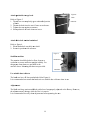
Stabilizee machine
The machhine should be bolted to floor, benchh, or
worktablle to ensure sufficient
s
uppright stabilitty. For
thispurpoose 8mm holles are proviided in the
machine’’sbase. Moun
nting hardw
ware not provvided.
Handwheel
Dust Poort
Use suitaable dust co
ollector
The bandd saw has a 4"
4 dust port included
i
(Seee Figure 6)..
It is recom
mmended to
o connect thee band saw to
t a suitable dust collectoor when in use.
Adjustm
ments
The bladde tracking, tension
t
and blade
b
guidess have beenpproperly adjuusted at the factory. How
wever,
the adjusstmentsmay change
c
while the saw is in transit.
It is recom
mmended to
o verify thesee adjustmentts beforeopeerating the saaw.
14
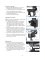
Changing and adjusting the saw blade
This band saw is factory-equipped with a general-purpose,woodcutting blade; the saw blade is
set prior to delivery.
To change the saw blade, follow the procedure below:
WARNING: To avoid injury from unexpected starting,whenever changing the saw
blade or carrying outadjustments, switch the band saw off and remove thepower cord
from the main outlet. To avoid injury tohands when handling the saw blade, wear
gloveswhenever necessary.
Blade
Figure 7
1. Remove the rip fence and the guide rail from the
Tension
table.
Knob
2. Open the upper and lower doors by turning the
door locking knobs.
3. Loosen the tracking Lock Nut (See figure 7).
Tracking
4. Loosen the blade tension by turning the bladeKnob
tension knob on the top of the upper-wheel
Tracking
housing counterclockwise until the saw blade has
Lock
slackened (viewedfrom above) or turn quick
release lever to the right.See Figure 7.
5. Remove the saw blade from the upper and lower wheels.
6. When fitting the new saw blade ensure the blade teeth are pointing downwards and towards
you at the position where the saw blade passes through the table.
7. Re-tension the new saw blade and check the saw blade tracking by turning the upper wheel
by hand.The saw blade should run in the center of the band saw wheels.
8. Tighten the tracking lock nut.
9. If you need to adjust the tracking of the saw blade, follow the procedures for TRACKING
THE SAW BLADE.
10. Replace the rip fence and the guide rail onto the table.
11. Close the upper and lower doors by turning the door locking knobs before reconnecting the
power supply.
Tracking the saw blade
Set the tracking of the saw blade before setting theblade guides.
Once the saw blade is installed and tensioned, track thesaw blade by adjusting the tracking knob
by hand (SeeFigure 7). The saw blade should run in the center ofthe band saw wheels. When the
correct adjustment isachieved lock the tracking knob with the locking nut.
15
Setting the cutting height
1. The upper blade guide should be set as close as is
practically necessary against the workpiece.
2. To adjust this height, loosen the locking knob in the
center of the adjusting knob (See Figure 8).
3. Set the blade guide to the required height by turning
the guidepost-adjusting knob.
4. Tighten locking knob after setting.
GuidepostAdjusting Knob
Locking
Knob
Figure 8
Adjusting the blade guides
NOTE: Upper and lower blade guides are adjusted inthe
same manner.See Figures 9 and 10.
1. To adjust the upper blade guides, first position the
right and left roller guides relative to the blade by
loosening set screw (A) and moving the guide
carrier until both roller guides are approximately
1⁄16" behind the gullets of the saw blade. Tighten set
screw (A).
2. Set both roller guides to within 1⁄32" of the saw
blade by loosening the thumb screw (B) and turning
the shaft (C) at rear of guide carrier. Do not set the
roller guides too close as this will adversely affect
the life of the saw blade. Tighten thumb screws.
3. Adjust the rear roller guide to be just clear of the
back of the saw blade by unlocking the set screw (D)
located on rear of guide carrier. Adjust shaft (E) and
then lock the set screw (D).
A
Figure 9
C
B
Guide Carrier
Figure 10
D
Rear Guide
E
B
Guide Carrier
Tilting the table
For bevel cuts, the table tilts 0 through 45 degrees.
1. To tilt the table, loosen the locking handle on the
table trunnion. Set the table to the required angle by
turning adjustment knob (See Figure 11). Secure
table in position by tightening locking handle.
2. It is recommended to verify the correct angle setting
using an angle guide or by making trial cuts in scrap
wood. Adjust the indicator accordingly by using a
screwdriver.
16
Indicator
Locking
Handle
Adjusting Knob
Figure 11
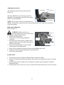
Adjusting the rip fence
Fence Body
The locking pressure of the rip fence has been
factory-set.
Figure 12
The fence handle has a cam action, press down
thehandle to clamp tightly to the table after setting
ripfence to desired position.
Fence Extrusion
NOTE: The rip fence can be used on both sides of
theblade. The rip fence extrusion needs to be positioned onthe side of the fence body that is
closest to the blade.
Blade speed adjustment
Refer to Figure 13
WARNING: Make surethe saw is
Figure 13
disconnectedfrom the power source before
attempting to change theblade speed.
1. Open lower housing door.
Handwheel
2. Loosen drive belt by turning handwheel
Brush
clockwise.
3. Position belt on desired pulley of blade wheel
andmotor. Belt must run on either both front or
Drive Belt
both rear pulleysonly.
4. Drive belt on front pulleys (nearest to blade
wheel)results in low blade speed.
5. Drive belt on rear pulleys (nearest to frame) results inhigh blade speed.
6. Tighten drive belt by turning handwheel counterclockwise.
7. Close lower housing door.
PUSH STICK
1. The push stick protects against accidental contact with the saw blade.
2. Always use the push stick when the distance between the saw blade and rip fence is less than
5 inches.
3. Hold the push stick at an angle of 25-30 degrees to the table surface and guide workpiece
through the blade.
4. When the push stick is not in use, store it on the hook located at the top rear of the saw frame.
17
BLADE SELECTION
1. Blades vary depending on type of material, size of workpiece and type of cut that is being
performed.
2. Characteristics which make blades different are width, thickness and pitch.
BLADE WIDTH
1. Width of blade describes distance from tip of a tooth to back of blade.
2. Width of blade affects rigidity of blade. A wider blade wanders less and produces a straighter
cut.
3. Width of blade also limits the smallest radius which can be cut. A 1⁄4″ wide blade can cut
about a 1⁄2″ radius.
BLADE THICKNESS
1. Blade thickness describes the distance between the sides of a blade. A thicker blade has more
rigidity and stronger teeth.
2. A narrow thick blade is used to cut curves while a wide thin blade is used to make long,
straight cuts.
BLADE PITCH
1. Pitch describes number of teeth per inch or tooth size. A blade with more teeth per inch
produces a smoother cut.
2. The type of material being cut determines the number of teeth that should be in contact with
the work piece.
3. For soft materials, the proper blade has between 6 to 8 teeth per inch.
4. When cutting hard materials where shocking is more detrimental, use a blade with 8 to 12
teeth per inch.
5. There should always be at least three teeth in contact with cut to avoid shocking the blade.
6. Blade shocking occurs when pitch is too large and blade tooth encounters too much material.
This can strip teeth from blade.
7. Blade manufacturers are prepared to supply information about blades for specific
applications.
TYPE OF CUT
1. Contour cutting is done by guiding workpiece freehanded to produce curved shapes.
2. Beveled cutting is done by tilting saw table and using proper work guide method.
3. Regardless of which work guiding method is used, a workpiece which overhangs table by
more than 5" needs proper support.
18
CONTOUR SAWING
1. When contour sawing, use both hands to keep workpiece flat against table and guided along
desired path.
2. Avoid positioning hands in line with the blade. If hands slip, they may contact blade.
3. Try to stand in front of the saw. Place hands over the portion of the table to the right of the
blade before cutting.
4. Cut small corners by sawing around them. Saw to remove scrap until desired shape is
obtained.
BEVEL CUTTING
1.
2.
3.
4.
Perform bevel cutting by tilting table to desired degree.
Unlock table by loosening the locking handle located on the backside of the unit
Tilt table to desired position.
Lock table in position by tightening locking handle.
MITER GAUGE
Use miter gauge for securing and holding workpiece at desired angle to produce angled cuts. Use
scale to adjust gauge to desired angle. Insert gauge bar into table slot at table's front edge.
WARNING: Never use miter gauge and rip fence at thesame time. The blade might
bind in the workpiece.
Operator could be injured and/or workpiece could bedamaged.
BLADE CLEANING BRUSH
Refer to Figure 13.
Make sure that brush is in contact with blade to properlyremove foreign particles from drive
wheel.
19
Operation
ON/OFF Switch(Figure 14)
1. To turn the saw ON, move the switch to the up (ON)
position.
2. To turn the saw OFF, move the switch to the down
(OFF) position.
3. To lock the switch in the OFF position:
Figure 14
a) Wait until the band saw has come to a complete
stop.
b) Remove the switch key from the switch housing. Store the switch key in a safe place.
4. To unlock the switch and turn the saw ON, insert the switch key into the switch, and move
the switch to the ON position.
General Cutting
WARNING: Operating a band saw involves a certain amount of hazard. Read the
instructions and plan your work before cutting a workpiece.
Use scrap lumber to check the settings and to get the feel of operating the band saw before
attempting regular work.
Do not turn the power on before all adjustments have been made. Check to make sure the upper
guard is in place. Always keep the upper blade guard close to your work, approximately 1/8" (3.2
mm) above the workpiece.
Do not force the workpiece against the blade. Light contact permits easier cutting and prevents
unwanted friction and heating of the blade.
Sharp saw blades need limited pressure for cutting. Steadily move the workpiece against the
blade without forcing it.
Use the band saw for straight-line operations such as crosscutting, ripping, miter cutting,
beveling, compound cutting, and resawing.
To avoid twisting the blade, do not turn sharp corners; instead, saw around corners.
A band saw is basically a “curve-cutting” saw. It is not capable of doing intricate inside cutting
as can be done with a scroll saw.
WARNING: Do not use this band saw to cut ferrous metals.
20
Cutting Curves
When cutting curves, carefully turn the work piece so the blade follows without twisting. If the
curve is so sharp that you repeatedly back up and cut new kerf, use either a narrower blade or a
blade with more set (teeth further apart). When a blade has more set, the work piece turns easier
with a rougher cut.
When changing a cut, do not withdraw the work piece from the blade. The blade may get drawn
off the wheels. To change a cut, turn the work piece and saw out through the scrap material area.
When cutting long curves, make relief cuts as you go along.
Maintenance
WARNING: For your own safety, turn the switch OFF and remove the plug from the
electrical outlet before performing maintenance or lubricating the band saw.
Remove the sawdust from the inside of the housing and blow out the sawdust from the motor.
Clean off pitch that accumulates on the table, blade guides, and bearings.
Remove pitch and dust from the upper and lower wheels using a stiff brush. Do not use solvents.
Apply a thin coat of automotive polish to the tabletop for a slick surface.
Replace the wheel tires when worn.
WARNING: Replace the power cord immediately if it is worn, cut, or damaged in any
way.
21
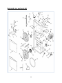
Exploded view and parts list
22
Item #
1
2
3
4
5
6
7
8
9
10
11
12
13
14
15
16
17
18
19
20
21
22
23
24
25
26
27
Stock #
3914-101
3914-102
3914-103
3914-104
3914-105
3914-106
3914-107
3914-108
3914-109
3914-110
3914-111
3914-112
3914-113
3914-114
3914-115
3914-116
3914-117
3914-118
3914-119
3914-120
3914-121
3914-122
3914-123
3914-124
3914-125
3914-126
3914-127
Description
Lower Door Assembly
Upper Door Assembly
Retaining Ring
Upper Wheel Shaft
Tension Block
Flange Nut
Guide Plate
Nut
Spring
Shaft
Retaining Ring
Tension Bracket Frame
Push Stick
Hook
Hex Nut
Cap
Tension Knob
Jam Nut
Threaded Rod
Bushing
Tension Release Handle
Hex Nut
Spacer
Cam
Hex Head Bolt
Flat Washer
Tracking Knob
Item #
28
29
30
31
32
33
34
35
36
37
38
39
40
41
42
43
44
45
46
47
48
49
50
51
52
53
54
23
Stock #
3914-128
3914-129
3914-130
3914-131
3914-132
3914-133
3914-134
3914-135
3914-136
3914-137
3914-138
3914-139
3914-140
3914-141
3914-142
3914-143
3914-144
3914-145
3914-146
3914-147
3914-148
3914-149
3914-150
3914-151
3914-152
3914-153
3914-154
Description
Wing Nut
Flat Washer
Hex Head Bolt
Locking Knob
Socket Head Bolt
Motor
Set Screw
Motor Pulley
Lower Wheel Shaft
Dust Port
Shaft
Collar
Handwheel Assembly
Hex Head Bolt
Switch Assembly
Bearing 6202zz
Upper Wheel
Brush Assembly
Belt Tension Drum Assembly
Lock Washer
Drive Pulley
Lower Wheel
Socket Head Bolt
Tire
Drive Belt
Blade
Capacitor
24
Item #
1
2
3
4
5
6
7
8
9
10
11
12
13
14
15
16
17
18
19
20
21
22
23
24
25
26
27
28
29
30
31
32
33
Stock #
3914-201
3914-202
3914-203
3914-204
3914-205
3914-206
3914-207
3914-208
3914-209
3914-210
3914-211
3914-212
3914-213
3914-214
3914-215
3914-216
3914-217
3914-218
3914-219
3914-220
3914-221
3914-222
3914-223
3914-224
3914-225
3914-226
3914-227
3914-228
3914-229
3914-230
3914-231
3914-232
3914-233
Description
Tap Screw
Plate
Rack
Guide Post
Pressure Plate
Pin
Rack Gear and Shaft
Guide Block Pin
Guide Carrier
Tap Screw
Sliding Guard
Spacer
Threaded Rod
Guide Shaft
Adjusting Nut
Bearing 627zz
Guide Block
Shaft
Thumb Screw
Guide Adjusting Knob
Table
Table Insert
Flat Washer
Wing Bolt
Fence Rail Left Cap
Fence Rail
Fence Rail Right Cap
Scale
Hex Nut
Knob
Nut
Shaft
Gear
Item #
34
35
36
37
38
39
40
41
42
43
44
45
46
47
48
49
50
51
52
53
54
55
56
57
58
59
60
61
62
63
64
65
25
Stock #
3914-234
3914-235
3914-236
3914-237
3914-238
3914-239
3914-240
3914-241
3914-242
3914-243
3914-244
3914-245
3914-246
3914-247
3914-248
3914-249
3914-250
3914-251
3914-252
3914-253
3914-254
3914-255
3914-256
3914-257
3914-258
3914-259
3914-260
3914-261
3914-262
3914-263
3914-264
3914-265
Description
Locking Handle
Spacer
Lower Blade Guard
Trunnion
Angle Scale
Spacer
Trunnion Bracket
Bolt
Indicator
Screw
Bolt
Bolt
Locking Pin
Lower Guide Seat
Handle Assembly
Cam
Tap Screw
Pressure Plate
Fence Carrier
Shaft
Lens
Plate
Cap
Bolt
Wing Nut
Washer
Fence Bracket
Bolt
Plate
Fence
Rip Fence Assy
Miter Gauge
Item #
1
2
3
4
5
6
7
Stock #
3914-301
3914-302
3914-303
3914-304
3914-305
3914-306
3914-307
Description
Left Panel
Brace
Rear Panel
Shelf
Right Panel
Base
Door Assembly
Item #
8
9
10
11
12
13
14
Stock #
3914-308
3914-309
3914-310
3914-311
3914-312
3914-313
3914-314
26
Description
Screw
Flat Washer
Flat Washer
Bolt
Screw
Nut
Bolt
Limited two years warranty
WEN Products is committed to build tools that are dependable for years. Our warranties are consistent with this commitment and
our dedication to quality.
LIMITED WARRANTY OF WEN CONSUMER POWER TOOLS PRODUCTS FOR HOME USE
GREAT LAKES TECHNOLOGIES, LLC ("Seller") warrants to the original purchaser only, that all WEN consumer power tools
will be free from defects in material or workmanship for a period of two (2) years from date of purchase. Ninety days for all
WEN products, if the tool is used for professional use.
SELLER'S SOLE OBLIGATION AND YOUR EXCLUSIVE REMEDY under this Limited Warranty and, to the extent
permitted by law, any warranty or condition implied by law, shall be the repair or replacement of parts, without charge, which are
defective in material or workmanship and which have not been misused, carelessly handled, or misrepaired by persons other than
Seller or Authorized Service Center. To make a claim under this Limited Warranty, please contact us at 1-800-232-1195.. To
acquire service, you will have to provide proof of purchase and may be asked to ship the tool back to us freight prepaid.
THIS LIMITED WARRANTY DOES NOT APPLY TO ACCESSORY ITEMS SUCH AS CIRCULAR SAW BLADES, DRILL
BITS, ROUTER BITS, JIGSAW BLADES, SANDING BELTS, GRINDING WHEELS AND OTHER RELATED ITEMS.
ANY IMPLIED WARRANTIES SHALL BE LIMITED IN DURATION TO ONE (1) YEAR FROM DATE OF PURCHASE.
SOME STATES IN THE U.S., SOME CANADIAN PROVINCES DO NOT ALLOW LIMITATIONS ON HOW LONG AN
IMPLIED WARRANTY LASTS, SO THE ABOVE LIMITATION MAY NOT APPLY TO YOU.
IN NO EVENT SHALL SELLER BE LIABLE FOR ANY INCIDENTAL OR CONSEQUENTIAL DAMAGES (INCLUDING
BUT NOT LIMITED TO LIABILITY FOR LOSS OF PROFITS) ARISING FROM THE SALE OR USE OF THIS PRODUCT.
SOME STATES IN THE U.S. AND SOME CANADIAN PROVINCES DO NOT ALLOW THE EXCLUSION OR
LIMITATION OF INCIDENTAL OR CONSEQUENTIAL DAMAGES, SO THE ABOVE LIMITATION OR EXCLUSION
MAY NOT APPLY TO YOU.
THIS LIMITED WARRANTY GIVES YOU SPECIFIC LEGAL RIGHTS, AND YOU MAY ALSO HAVE OTHER RIGHTS
WHICH VARY FROM STATE TO STATE IN THE U.S., PROVINCE TO PROVINCE IN CANADA AND FROM
COUNTRY TO COUNTRY.
THIS LIMITED WARRANTY APPLIES ONLY TO PORTABLE ELECTRIC TOOLS, BENCH POWER TOOLS, OUTDOOR POWER EQUIPMENT
AND PNUMATIC TOOLS SOLD WITHIN THE UNITED STATES OF AMERICA, CANADA AND THE COMMONWEALTH OF PUERTO
RICO. FOR WARRANTY COVERAGE WITHIN OTHER COUNTRIES, CONTACT THE WEN CUSTOMER
SUPPORT.
27