1
2
Table of contents
Technical data………………………………………………………..
General safety rules…………………………………………………..
Specific safety rules for band saws…………………………………..
Electrical information………………………………………………...
Know your band saw…………………………………………………
Assembly and adjustments……………………………………………
Operation……………………………………………………………..
Maintenance………………………………………………………….
Exploded view and parts list………………………………………….
Warranty………………………………………………………………
Technical data
10 inch Band Saw with Stand
Model:
3912
Motor:
Motor speed:
Blade speed:
Blade length:
Blade width range:
Depth of throat at 90°:
Maximum depth of cut at 90°:
Maximum depth of cut at 45°:
Table size:
Table tilt:
Weight:
120 V, 60 Hz, 3.4 A
1720 RPM (no load)
2920 FPM
67-3/8"
1/8" to 1/2"
9-1/2"
4"
2"
13-1/9"x13-3/8"
0° to 45°
94.5 lbs
3
3
4
6
7
9
10
17
18
19
24
General safety rules
Safety is a combination of common sense, staying alert and knowing how your band saw works.
SAVE THESE SAFETY INSTRUCTIONS.
WARNING: To avoid mistakes that could cause serious injury, do not plug in the
band saw until the following steps have been read and understood.
1. READ and become familiar with this entire instruction manual. LEARN the tool’s
applications, limitations, and possible hazards.
2. AVOID DANGEROUS CONDITIONS. Do not use power tools in wet or damp areas or
expose them to rain. Keep work areas well lit.
3. DO NOT use power tools in the presence of flammable liquids or gases.
4. ALWAYS keep your work area clean, uncluttered, and well lit. DO NOT work on floor
surfaces that are slippery with sawdust or wax.
5. KEEP BYSTANDERS AT A SAFE DISTANCE from the work area, especially when the
tool is operating. NEVER allow children or pets near the tool.
6. DO NOT FORCE THE TOOL to do a job for which it was not designed.
7. DRESS FOR SAFETY. Do not wear loose clothing, gloves, neckties, or jewelry (rings,
watches, etc.) when operating the tool. Inappropriate clothing and items can get caught in
moving parts and draw you in. ALWAYS wear non-slip footwear and tie back long hair.
8. WEAR A FACE MASK OR DUST MASK to fight the dust produced by sawing operations.
WARNING: Dust generated from certain materials can be hazardous to your health.
Always operate the band saw in a well-ventilated area and provide for proper dust
removal. Use dust collection systems whenever possible.
9. ALWAYS remove the power cord plug from the electrical outlet when making adjustments,
changing parts, cleaning, or working on the tool.
10. KEEP GUARDS IN PLACE AND IN WORKING ORDER.
11. AVOID ACCIDENTAL START-UPS. Make sure the power switch is in the OFF position
before plugging in the power cord.
12. REMOVE ADJUSTMENT TOOLS. Always make sure all adjustment tools are removed
from the saw before turning it on.
4
General safety rules (continued)
13. NEVER LEAVE A RUNNING TOOL UNATTENDED. Turn the power switch to OFF.
Do not leave the tool until it has come to a complete stop.
14. NEVER STAND ON A TOOL. Serious injury could result if the tool tips or is accidentally
hit. DO NOT store anything above or near the tool.
15. DO NOT OVERREACH. Keep proper footing and balance at all times. Wear oilresistantrubber-soled footwear. Keep the floor clear of oil, scrap, and other debris.
16. MAINTAIN TOOLS PROPERLY. ALWAYS keep tools clean and in good working order.
Follow instructions for lubricating and changing accessories.
17. CHECK FOR DAMAGED PARTS. Check for alignment of moving parts, jamming,
breakage, improper mounting, or any other conditions that may affect the tool’s operation.
Any part that is damaged should be properly repaired or replaced before use.
18. MAKE THE WORKSHOP CHILDPROOF. Use padlocks and master switches and
ALWAYS remove starter keys.
19. DO NOT operate the tool if you are under the influence of drugs, alcohol, or medication
that may affect your ability to properly use the tool.
20. USE SAFETY GOGGLES AT ALL TIMES that comply with ANSI Z87.1. Normal safety
glasses only have impact resistant lenses and are not designed for safety. Wear a face or
dust mask when working in a dusty environment. Use ear protection such as plugs or muffs
during extended periods of operation.
5
Specific safety rules for band saws
1. To avoid injury from unexpected movement, make sure the saw is on a firm, level surface
and properly secured to prevent rocking. Make sure there is adequate space for operations.
Bolt the saw to a support surface to prevent slipping or sliding during operation.
2. Turn off and unplug the saw before moving it.
3. Use the correct size and style of blade.
4. Make sure the blade teeth point down and toward the table.
5. Blade guide, supports, bearings, and blade tension must be properly adjusted to avoid
accidental blade contact and to minimize blade breakage. To maximize blade support,
always adjust the upper blade guide and blade guard so that it barely clears the workpiece.
6. Table TILT lock handle should be tight.
7. Use extra caution with very large, very small, or awkward workpieces.
8. Use extra supports to prevent workpieces from sliding off the tabletop.
9. Workpieces should be secured so they don’t twist, rock, or slip while being cut.
10. Plan intricate or small work carefully to avoid pinching the blade. Avoid awkward
operations and hand positions to prevent accidental contact with the blade.
11. Small pieces should be secured with clamps or fixtures. Do not hold small pieces with your
hand because your fingers might go under the blade guard.
12. Support round work properly (use a V block or press it against the miter gauge) to prevent
the piece from rolling and the blade from biting.
13. Only cut one workpiece at a time. Make sure the table is clear of everything except the
workpiece and its guides before you turn the saw on.
14. Always WATCH the saw run before each use. If there is excessive vibration or unusual
noise, stop immediately. Turn the saw off. Unplug it immediately. Do not start the saw
again until the problem has been located and corrected.
15. To free any jammed material, turn the switch off. Remove the switch key and unplug the
saw. Wait for all moving parts to stop before removing the jammed material.
16. Don’t leave the work area until all moving parts have stopped. Shut off the power to master
switches. Remove the switch key from the band saw and store it in a safe place, away from
children. Childproof the workshop!
6
Electrical information
Grounding Instructions
IN THE EVENT OF A MALFUNCTION OR BREAKDOWN, grounding provides the path of
least resistance for electric current and reduces the risk of electric shock. This tool is equipped
with an electric cord that has an equipment-grounding conductor and a grounding plug. The
plug MUST be plugged into a matching outlet that is properly installed and grounded in
accordance with ALL local codes and ordinances.
DO NOT MODIFY THE PLUG PROVIDED. If it does not fit the outlet, have the proper outlet
installed by an electrician.
IMPROPER CONNECTION of the equipment-grounding conductor can result in electric shock.
The conductor with the green insulation (with or without yellow stripes) is the equipmentgrounding conductor. If repair/replacement of the electric cord or plug is necessary, DO NOT
connect the equipment-grounding conductor to a live terminal.
CHECK with a licensed electrician or service personnel if you do not completely understand
the grounding instructions or if the tool is properly grounded.
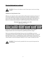
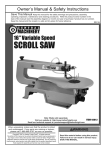
USE ONLY THREE-WIRE EXTENSION CORDS with 3-prong plugs and 3-prong outlets that
accept the tool's plug as shown in Fig. A. Repair or replace a damaged or worn cord
immediately.
CAUTION: In all cases, make certain the outlet in question is properly grounded. If you are
not sure if it is, have a licensed electrician check the outlet.
7
Electrical information (continued)
WARNING: This saw is for indoor use only. Do not expose to rain or use in damp
locations.
Guidelines for Using Extension Cords
Make sure your extension cord is in good condition. When using an extension cord, be sure to
use one heavy enough to carry the current your product will draw. An undersized cord will
cause a drop in line voltage resulting in loss of power and overheating. The table below shows
the correct size to be used according to cord length and nameplate ampere rating. When in
doubt, use a smaller-numbered gauge (the smaller the gauge number, the heavier the cord)
Minimum Gauge for Extension Cords (AWG)
(when using 120 V only)
Ampere Rating
More Than
Not More Than
0 Amp
6 Amp
Total Length of Cord in feet
50 Feet
100 Feet
16 Gauge
16 Gauge
25 Feet
18 Gauge
150 Feet
14 Gauge
Be sure your extension cord is properly wired and in good condition. Always replace a
damaged extension cord or have it repaired by a qualified person before using it.
Protect your extension cords from sharp objects, excessive heat and damp or wet areas.
Use a separate electrical circuit for your tools. This circuit must not be less than a #12 wire and
should be protected with a 15 A time-delayed fuse. Before connecting the motor to the power
line, make sure the switch is in the OFF position and the electric current is rated the same as the
current stamped on the motor nameplate. Running at a lower voltage will damage the motor.
WARNING: This tool must be grounded while in use to protect the operator from
electrical shock.
8
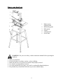
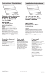
Know your band saw
1
2
3
4
1
5
2
3
4
5
6
6
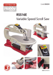
Blade tension
adjusting knob
Ball bearing guide
Miter gauge
Switch
Locking fence
Metal stand
WARNING: For your own safety, read the instruction manual before operating the
band saw.
1.
2.
3.
4.
5.
6.
Wear eye protection.
Do not wear gloves, neckties, jewelry, or loose clothing.
Make sure the saw is on a firm, level surface and properly secured.
Use only the recommended accessories.
Use extra caution with very large, very small, or awkwardly-shapedworkpieces.
Keep hands away from blade at all times to prevent accidental injury.
9
Assembly and adjustments
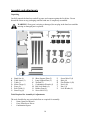
Unpacking
Carefully unpack the band saw and all its parts, and compare against the list below. Do not
discard the carton or any packaging until the band saw is completely assembled.
WARNING: If any part is missing or damaged, do not plug in the band saw until the
missing or damaged part is replaced.
A
B
C
D
E
F
G
Band Saw (1)
Table Insert (1)
Table (1)
Miter Gauge (1)
Fence (1)
Rail Guide (1)
Stand Leg (4)
H
J
K
L
M
N
O
Short Support Plate (2)
Long Support Plate (2)
Wrench (1)
Combination Wrench (1)
Rail Lock Knob (4)
Rubber Foot (4)
Screw M6x32 (1)
P
Q
R
S
T
U
Tools Required for Assembly & Adjustments
The tools listed below are not included but are required for assembly.
2
14mm Open End Wrench
1
Cross Point Screw Driver
1
Combination Square
10
Screw M6x12 (4)
Bolt (16)
Flat Washer 8 (20)
Nut 8 (16)
Nut 6 (1)
Lock Washer (4)
Assembly and adjustments (continued)
WARNING:Unplug the machine from the power source before assembling or
adjusting anything. Failure to comply may cause serious injury.
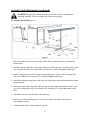
To Assemble the Stand(Figure 1)
1. Place the band saw (A) on its back either on the floor or (preferably) on a workbenchas
shown above.
2. Assemble the four legs (G) to the inside of the base of the band saw, securing each leg with
two carriage bolts (Q1), flat washers (R1) and nuts (S1). Only hand-tighten at this time.
3. Attach a long plate (J) to the rear legs as shown in Figure 1. Secure with 2 carriage bolts
(Q2), flat washers (R2), and nuts (S2). Only hand-tighten at this time.
4. Attach the remaining long plate to the front legs in the same manner described above, handtightening only.
5. Attach two short plates (H) to the right legs and left legs in the same manner. Secure each
leg with 2 carriage bolts (Q3), flat washers (R3), and nuts (S3). Only hand-tighten at this
time.
6. Slip rubber feet (N) onto the ends of the stand legs.
7. Place the saw and stand upright on a level surface. Make sure that all four legs are
contacting the surface.
8. Tighten all nuts with a 13mm socket or wrench.
11
Assembly and adjustments (continued)
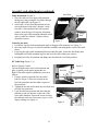
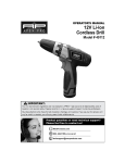
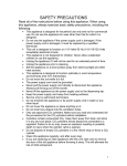
Table Installation (Figure 2)
1. Place the table on to the upper table trunnion,
takingcare when passing the saw blade through
the slot ofthe table (see Figure 2).
2. Attach M6 x 30 hex head bolt and nut to hole
next to theinsert in the table’s bottom. Locate
four M6 x 16 hex boltsand four M6 serrated
washers from the bag of looseparts. Mount the
table to the upper table trunnion andinstall a bolt
with a washer in each hole. Tighten with an
adjustable wrench.
Hex Bolts
Stop Bolt
Trunnion
Flange
Bolt
Figure 2
Centering the table
1. Loosen the four hex bolts mounting the table to theupper table trunnion (see Figure 2).
2. Move the table sideways as required, until the sawblade runs through the center of the table
insert.
3. If moving the upper-table trunnionstill doesn’tcenter the table, loosen the four flange nuts
holdingthe lower-table trunnion in place and move the table sidewaysto center it.
4. Retighten hex bolts for trunnion and flange nuts. Recheck the saw blade position.
90° Table Stop (Figure 3, 4)
Refer to Figures 3 and 4.
Loosen the knob on the lower table trunnion and
place a suitably sized square against the saw
blade. If the table requires adjustment, proceed as
follows:
1. Using a wrench, release the hex nut on the
bolt (see Figure 3).Place the wrench on the
hex bolt and adjust until the table is square to
the saw blade.
2. Tighten the hex nut and recheck the saw blade and
the table for squareness.
3. Lock the table into position and check that the
indicator reads zero degrees on the side of the
lower table trunnion. Loosen the screw securing
the indicator and reset if necessary to give a zerodegree reading (see Figure 4).
Figure 3
Hex Nut
Hex Bolt
Figure 4
12
Square
Assembly and adjustments (continued)
Rail Guide and Fence Installation (Figure 4 & 5)
Figure 4
Rail Guide
Attach the rail guide (Fig. 4) to the front of the table.
Secure with four lock knobs.
Figure 5
Place fence assembly (Fig. 5) onto the table at the
miter slot.
The rear hook should engage the rear of the table. The
fence body should engage the rail guide.
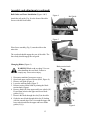
Changing Blades (Figure 6)
Blade tension knob
WARNING!Blade teeth are sharp! Use care
when handling the saw blade. Failure to
comply may cause serious injury.
1.
2.
3.
4.
5.
Disconnect machine from power source.
Open both upper and lower doors (K&L, Figure 8).
Remove rail guide (Figure 4).
Loose the tracking knob (Figure 7).
Release tension on the blade by turning the blade
tension knob (Figure).
6. Remove blade (H) from upper and lower wheels (M,
R) and from between the upper and lower blade
guides (N, Q).
7. Remove the blade through the slot (P) in the table.
8. Guide the new blade through table slot (P) leading
with the smooth edge. Place it around the upper and
lower wheels and into the upper and lower blade
guides (N, Q).
13
Figure 6
Assembly and adjustments (continued)
Note: The blade teeth should face the operator and should point down towards the table.
9. Position the blade to track in the middle of the
rubber tires on the wheels (M, R).
10. Engage tension on the blade by turning the blade
tension knob (Figure 6).
11. Tighten the tracking knob (Figure7).
12. Replace rail guide (Figure 4).
Before operating the saw, check that the blade is
tracking and has proper tension as described in
“Adjusting Blade Tension” and “Adjusting Blade
Tracking”
Figure 7
Tracking knob
Lock Knob
Adjusting Blade Tension (Figure 6)
1. Disconnect machine from power source. The blade tension knob (Figure 6) is used to adjust
blade tension.
Note: All bearings on upper and lower guides must be clear of blade (see Blade Guide and
Guide Bearing adjustments on following page).
2. Apply just enough tension to take the slack out of the blade.
3. Turn one wheel (R, Figure 6) a few times to allow the blade to position itself in the center
of the tire.
Note: If blade does not center see Adjusting Blade Tracking section.
Note: A meter is recommended to precisely set tension for the size of blade used.
Note: As you become more experienced with the saw, you may find it necessary to change the
blade tension from the initial setting. Changes in blade width and the type of material being cut
will have an effect on blade tension.
Note: Keep in mind that too little or too much blade tension can cause blade breakage.
Adjusting Blade Tracking (Figure 7)
WARNING:Disconnect machine from the power source! Never adjust blade tracking
with the machine running! Failure to comply may cause serious injury!
Tracking refers to how the blade is situated upon the wheels while in motion. The blade should
track in the center of both wheels.
The blade must be slightly tensioned (see previous section) before adjusting blade tracking.
Make sure blade guides and bearings (N&Q, Figure 6) do not interfere with the blade. If blade
tracking is required, blade guide adjustment is described on the following page.
14
Assembly and adjustments (continued)
1. Open the upper and lower doors. Rotate the wheel forward by hand, and observe the
position of the blade on the wheel. It should be in the center of the wheel.
2. Loosen the lock knob (Figure 7) and make adjustment with tracking knob (Figure 7) while
rotating wheel by hand.
3. Tightening the tracking knob slightly will move the blade so it tracks towards the rear of
machine. Loosening the tracking knob slightly will cause the blade to track toward the front
of the machine.
4. After blade is tracking in the center of the wheel, tighten the lock knob (Figure 7).
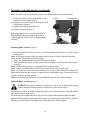
Blade guide adjustment(Figure 8,9& 10)
Figure 8
The upper blade guide assembly (3, Figure 8) should be
adjusted to just above the material being cut. To adjust:
loosenthe lock knob (2, Figure 8) and raise or lower the
upper blade guide assembly (3, Figure 8) by turning the
height adjustment knob (1, Figure 8).
1
2
The blade guide assembly consists of two roller guides
3
(bearings) positioned on each side of the blade to provide
blade stability. A third guide (thrust bearing) is positioned
behind the blade to provide blade support.
There are two blade guide assemblies - an upper assembly and a lower assembly (see Figure 11).
Adjustments are performed in the same manner for each assembly. Each assembly must be
adjusted in turn using the adjustment procedures outlined below.
Figure 9
Thrust Bearing Adjustment (Figure 9)
WARNING:Disconnect machine from the
power source! Never make adjustments with
the machine running! Failure to comply may
cause serious injury!
1. Disconnect machine from power source.
Note: Blade must already be tensioned and tracking
properly.
2. For the upper thrust bearing, loosen thumbscrew (B).
For the lower blade guide, loosen setscrew (B) with
the 3mm hex wrench provided.
3. Slide the adjustment shaft (C) so the blade is
positioned in the middle of the thrust bearing (A).
The thrust bearing (A) is mounted on a concentric shaft
(C). When the shaft is rotated, the relative position of
the bearing to the back of the blade can be changed.
4. Rotate the adjustment shaft (C) so the thrust bearing
(A) just clears the back of the saw blade.
5. Tighten thumbscrew/setscrew (B).
15
Upper blade guide assembly
Lower blade guide assembly
Assembly and adjustments (continued)
If a blade is being replaced with a new one of a different size, the adjustment described above
may fall out of range and further adjustment may be required as follows:
Loosen the hex cap screw (G, not visible) with a 10mm wrench and adjust the entire assembly
backwards or forwards to clear the back of the saw blade. Tighten screw (G), and then fine-tune
the adjustment by repeating the first part of this step.
6. Secure the roller guide (A) by tightening the thumbscrew (B, upper guide) or setscrew (B,
lower guide).
Figure 10
Guide Bearing Adjustment(Figure 10)
WARNING:Disconnect machine from the
power source! Never make adjustments with
the machine running! Failure to comply may
cause serious injury!
Disconnect machine from power source.
Note: Blade must already be tensioned and tracking
properly.
Upper blade guide
assembly
For the upper-blade guide, loosen two thumbscrews (E).
For the lower blade guide, loosen two setscrews (E) with
the 3mm hex wrench provided.
Slide the adjustment shaft (F) to position each roller
guide (D) approximately 1/16" behind the gullets of the
saw blade.
Lower blade guide assembly
The roller guide (D) is mounted on a concentric shaft (F). When the shaft is rotated, the relative
position of the guide to the blade can be changed.
Rotate each adjustment shaft (F) to position the guides (D) within 1/32" of the saw blade.
Secure the roller guides (D) by tightening thumbscrews (E, upper guide) or setscrews (E, lower
guide).
16
Operation
ON/OFF Switch(Figure 11)
1. To turn the saw ON, move the switch to the up (ON)
position.
2. To turn the saw OFF, move the switch to the down
(OFF) position.
3. To lock the switch in the OFF position:
Figure 11
a) Wait until the band saw has come to a complete
stop.
b) Remove the safety key from the switch housing. Store the safety key in a safe place.
4. To unlock the switch and turn the saw ON, insert the safety key into the switch, and move
the switch to the ON position.
General Cutting
WARNING: Operating a band saw involves a certain amount of hazard. Read the
instructions and plan your work before cutting a workpiece.
Use scrap lumber to check the settings and to get the feel of operating the band saw before
attempting regular work.
Do not turn the power on before all adjustments have been made. Check to make sure the upper
guard is in place. Always keep the upper blade guard close to your work; approximately 1/8"
(3.2 mm) above the workpiece.
Do not force the workpiece against the blade. Light contact permits easier cutting and prevents
unwanted friction and heating of the blade.
Sharp saw blades need minimal pressure for cutting. Steadily move the workpiece against the
blade without forcing it.
Use the band saw for straight-line operations such as crosscutting, ripping, miter cutting,
beveling, compound cutting, and resawing.
To avoid twisting the blade, do not turn sharp corners; instead, saw around corners.
A band saw is basically a “curve-cutting” saw. It is not capable of doing intricate inside cutting
as can be done with a scroll saw.
WARNING: Do not use this band saw to cut ferrous metals.
17
Operation (cont.)
Cutting Curves
When cutting curves, carefully turn the work piece so the blade follows without twisting. If the
curve is so sharp that you repeatedly back up and cut new kerf, use a narrower blade, or a blade
with more set (teeth further apart). When a blade has more set, the work piece turns easier but
cuts rougher.
When changing a cut, do not withdraw the work piece from the blade. The blade may get drawn
offthe wheels. To change a cut, turn the work piece and saw out through the scrap material area.
When cutting long curves, make relief cuts as you go along.
Maintenance
WARNING: For your own safety, turn the switch OFF and remove the plug from the
electrical outlet before performing maintenance or lubricating the band saw.
Remove the sawdust from the inside of the housing and blow out the sawdust from the motor.
Clean off pitch that accumulates on the table, blade guides, and bearings.
Remove pitch and dust from the upper and lower wheels using a stiff brush. Do not use solvents.
Apply a thin coat of automotive polish to the tabletop for a slick surface.
Replace the wheel tires when worn.
WARNING: Replace the power cord immediately if it is worn, cut, or damaged in
any way.
18
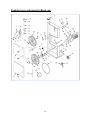
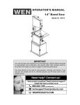
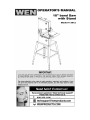
Exploded view and parts list (Band saw)
19
Exploded view and parts list (Band saw)
Item#
1
2
3
4
5
6
7
8
9
10
11
12
13
14
15
16
17
18
19
20
21
22
23
24
25
26
Stock#
3912-101
3912-102
3912-103
3912-104
3912-105
3912-106
3912-107
3912-108
3912-109
3912-110
3912-111
3912-112
3912-113
3912-114
3912-115
3912-116
3912-117
3912-118
3912-119
3912-120
3912-121
3912-122
3912-123
3912-124
3912-125
3912-126
Description
Door Locking Knob
Lower Door Assembly
Upper Door Assembly
Retaining Ring
Upper Wheel Shaft
Tension Block
Flange Nut
Tension Bracket Frame
E-Ring
Shaft
Spring
Shaft
Nut
Threaded Rod
Jam Nut
Tension Knob
Cap
Flat Washer
Hex Head Bolt
Tracking Knob
Wing Nut
Flat Washer
Motor
Carriage Bolt
Motor Mount Plate
Lock Washer
Item#
27
28
29
30
31
32
33
34
35
36
37
38
39
40
41
42
43
44
45
46
47
48
49
50
51
20
Stock#
3912-127
3912-128
3912-129
3912-130
3912-131
3912-132
3912-133
3912-134
3912-135
3912-136
3912-137
3912-138
3912-139
3912-140
3912-141
3912-142
3912-143
3912-144
3912-145
3912-146
3912-147
3912-148
3912-149
3912-150
3912-151
Description
Hex Head Bolt
Lower Wheel Shaft
Hex Head Bolt
Jam Nut
Hex Nut
Hex Head Bolt
Dust Port
Line Cord
Strain Relief
Switch Plate
Switch
Bearing 6000zz
Upper Wheel
Brush Assembly
Motor Pulley
Key
Set Screw
Lock Washer
Hex Nut
Drive Pulley
Lower Wheel
Screw
Blade
Drive Belt
Tire
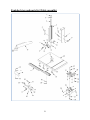
Exploded view and parts list (Table assembly)
21
Exploded view and parts list (Table assembly)
Item#
1
2
3
4
5
6
7
8
9
10
11
12
13
14
15
16
17
18
19
20
21
22
Stock#
3912-201
3912-202
3912-203
3912-204
3912-205
3912-206
3912-207
3912-208
3912-209
3912-210
3912-211
3912-212
3912-213
3912-214
3912-215
3912-216
3912-217
3912-218
3912-219
3912-220
3912-221
3912-222
Description
Tap Screw
Cover
Rack
Plate
Guide Post
Guide Pin
Rack Gear and Shaft
Knob
Shaft
Upper Guide Seat
Tap Screw
Set Screw
Upper Guide Housing
Set Screw
Set Screw
Thrust Bearing Shaft
Ball Bearing 625zz
Lower Blade Guard
Rip Fence Assembly
Table
Table Insert
Flat Washer
Item#
23
24
25
26
27
28
29
30
31
32
33
34
35
36
37
38
39
40
41
42
43
44
22
Stock#
3912-223
3912-224
3912-225
3912-226
3912-227
3912-228
3912-229
3912-230
3912-231
3912-232
3912-233
3912-234
3912-235
3912-236
3912-237
3912-238
3912-239
3912-240
3912-241
3912-242
3912-243
3912-244
Description
Bolt
Fence Rail
Nut
Bolt
Carriage Bolt
Guide Piece
Screw
Indicator
Trunnion
Washer
Bolt
Trunnion Bracket
Bolt
Nut
Flat Washer
Wing Knob
Bearing
Nut
Washer
Roller Guide
Pilot Pin
Bolt
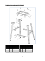
Exploded view and parts list (Stand)
Item#
1
2
3
4
5
Stock#
3912-301
3912-302
3912-303
3912-304
3912-305
Description
Bolt M8x40
Base
Wahser 8
Nut 8
Bolt M8x16
Item#
6
7
8
9
Stock#
3912-306
3912-307
3912-308
3912-309
23
Description
Stand Leg
Short Support Plate
Long Support Plate
Rubber Foot
Limited two years warranty
WEN Products is committed to build tools that are dependable for years. Our warranties are consistent with this commitment
and our dedication to quality.
LIMITED WARRANTY OF WEN CONSUMER POWER TOOLS PRODUCTS FOR HOME USE
GREAT LAKES TECHNOLOGIES, LLC ("Seller") warrants to the original purchaser only, that all WEN consumer power
tools will be free from defects in material or workmanship for a period of two (2) years from date of purchase. Ninety days for
all WEN products, if the tool is used for professional use.
SELLER'S SOLE OBLIGATION AND YOUR EXCLUSIVE REMEDY under this Limited Warranty and, to the extent
permitted by law, any warranty or condition implied by law, shall be the repair or replacement of parts, without charge, which
are defective in material or workmanship and which have not been misused, carelessly handled, or misrepaired by persons other
than Seller or Authorized Service Center. To make a claim under this Limited Warranty, please contact us at 1-800-232-1195..
To acquire service, you will have to provide proof of purchase and may be asked to ship the tool back to us freight prepaid.
THIS LIMITED WARRANTY DOES NOT APPLY TO ACCESSORY ITEMS SUCH AS CIRCULAR SAW BLADES,
DRILL BITS, ROUTER BITS, JIGSAW BLADES, SANDING BELTS, GRINDING WHEELS AND OTHER RELATED
ITEMS.
ANY IMPLIED WARRANTIES SHALL BE LIMITED IN DURATION TO ONE (1) YEAR FROM DATE OF PURCHASE.
SOME STATES IN THE U.S., SOME CANADIAN PROVINCES DO NOT ALLOW LIMITATIONS ON HOW LONG AN
IMPLIED WARRANTY LASTS, SO THE ABOVE LIMITATION MAY NOT APPLY TO YOU.
IN NO EVENT SHALL SELLER BE LIABLE FOR ANY INCIDENTAL OR CONSEQUENTIAL DAMAGES
(INCLUDING BUT NOT LIMITED TO LIABILITY FOR LOSS OF PROFITS) ARISING FROM THE SALE OR USE OF
THIS PRODUCT. SOME STATES IN THE U.S. AND SOME CANADIAN PROVINCES DO NOT ALLOW THE
EXCLUSION OR LIMITATION OF INCIDENTAL OR CONSEQUENTIAL DAMAGES, SO THE ABOVE LIMITATION
OR EXCLUSION MAY NOT APPLY TO YOU.
THIS LIMITED WARRANTY GIVES YOU SPECIFIC LEGAL RIGHTS, AND YOU MAY ALSO HAVE OTHER RIGHTS
WHICH VARY FROM STATE TO STATE IN THE U.S., PROVINCE TO PROVINCE IN CANADA AND FROM
COUNTRY TO COUNTRY.
THIS LIMITED WARRANTY APPLIES ONLY TO PORTABLE ELECTRIC TOOLS, BENCH POWER TOOLS,
OUTDOOR POWER EQUIPMENT AND PNUMATIC TOOLS SOLD WITHIN THE UNITED STATES OF AMERICA,
CANADA AND THE COMMONWEALTH OF PUERTO RICO. FOR WARRANTY COVERAGE WITHIN OTHER
COUNTRIES, CONTACT THE WEN CUSTOMER SUPPORT.
24