1
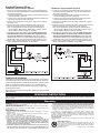
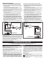
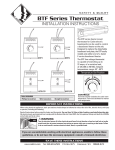
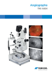
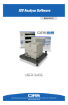
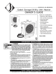
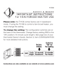
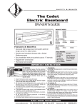
SMArT-BASeTM Thermostat
InstallatIon InstructIons
SBFT2
PLEASE READ THROUGH THESE INSTRUCTIONS BEFORE PROCEEDING
WITH INSTALLATION OF THE “SBFT2” THERMOSTAT INTO A CADET
SERIES “F” BASEBOARD
Tools Required: Phillips Screwdriver, Insulated Wire Connectors (Wire Nuts®),
Wire Strippers, Wire Cutters
IMPOrTAnT InSTrucTIOnS
When using electrical appliances, basic precautions should always be followed to reduce the risk of fire, electric shock, and
injury to persons, including the following:
Read all instructions before using this heater and thermostat.
All electrical work and materials must comply with the National Electric Code (NEC), the Occupational Safety and Health Act
(OSHA), and all state and local codes.
WARNING
Turn the electrical power off at the electrical panel board (circuit breaker or fuse box) and lock or tag the
panel board door to prevent someone from turning on power while you are working on the heater. Failure
to do so could result in serious electrical shock, burns, or possible death. If you are uncomfortable working with electrical appliances, unable to follow these guidelines, or do not have the necessary equipment, consult a licensed electrician.
InSTAllATIOn InSTrucTIOnS
For All Applications
The thermostat needs to be mounted into the same junction
box (wiring compartment) as the supplied electrical power.
Both junction boxes are equipped with a ground screw.
The installation of the SMART-BASE thermostat may require
a slight adjustment of the panel across the front of the heater,
to allow the thermostat to fit into the junction box unobstructed.
To do so, remove both junction box covers and unlatch the
bottom of the panel from its hangers. (Use a rubber-coated
tool, or hammer handle to remove the panel. Carefully pry
upward to remove.) Next, slide it back out of the junction box
opening to be used for the thermostat until its edge is just
hanging over the partition. Hold the panel and snap it back
on to its hangers. The thermostat will now have enough room
to fit into the junction box opening.
Replacing Existing BTF Thermostat Control
1. Remove screw attaching the existing BTF assembly
(thermostat and plate) to the baseboard case and carefully
pull it back to expose the wiring and connections. (Test with
meter or circuit tester to verify that no electrical power is
present before proceeding.)
2. If the power supply has been brought into the baseboard
at this junction box, undo the wiring connections and
remove the old thermostat assembly. Follow the appropriate
wiring diagram (“FIGURE A” for left end attachment,
“FIGURE B” for right end attachment) and the following
instructions “Baseboard/Thermostat Wiring” below to
connect the SBFT2 to the baseboard and power supply.
3. If the power supply has not been brought into the baseboard
at this junction box, remove the old thermostat assembly by
removing the wiring connections. The new thermostat
(SBFT2) must be located in the same junction box as the
supplied electrical power; therefore, strip 1/2” of insulation
from the two loose leads (created when the thermostat was
removed) and join the two wires back together using a wire
connector. Remove the end plate from the other junction
box and apply it to the junction box where the thermostat
was removed. Follow the appropriate wiring diagram
(“FIGURE A” for left end attachment, “FIGURE B” for right
end attachment) and the following further instructions
“Baseboard/Thermostat Wiring” to connect the SBFT2 to
the baseboard and power supply.
As Part of New Installation
Install the Cadet “F” series baseboard heater according to
the installation instructions supplied with the product. Keep
in mind the SBFT2 thermostat needs to be mounted into the
same junction box (wiring compartment) as the supplied
electrical power. Both junction boxes are equipped with a
ground screw.
SAVe TheSe InSTrucTIOnS
www.cadetco.com
Tel: 360-693-2505
P.O. Box 1675
Vancouver, WA
98668-1675
Baseboard/Thermostat Wiring
Thermostat in left junction box: (Figure A)
Thermostat in right junction box: (Figure B)
1. Locate and cut closed end splice of wires containing limit lead wire
and return wire (wire behind deflector). Strip 1/2” of insulation from
these two cut lead wires.
a. Join the lead wire from the limit with the lead wire from thermostat
terminal J5L2 with a connector.
b. Join the return wire (wire behind deflector) with the lead wire from
thermostat terminal J1T1 with a connector.
2. Connect the grounding lead of the power supply to the supplied
grounding screw.
3. Connect each of the remaining two power supply leads to each
lead from the thermostat rocker switch with a wire connector.
a. Be sure the panel does not interfere with the mounting of the
thermostat plate. Move panel if needed. (Using a rubber-coated
tool, or hammer handle; carefully pry upwards.)
4. Carefully push wiring back into junction box. Keep all wires away
from the Smart-Base circuit board. These wires may interfere with
the clock and thermostat’s performance. Hook upper edge of
faceplate under lip of case. Lower bottom edge of faceplate to
junction box surface and secure thermostat with mounting screw.
5. Rocker switch should be placed in the “O” (OFF) position. To finish
see the “Completion of Installation” section below.
1. Cut closed end splice from connection of element lead wire and
return wire (wire behind deflector). Strip 1/2” of insulation from
these two cut lead wires.
a. Join the lead wire from the element with the lead wire from
thermostat terminal J5L2 with a connector.
b. Join the return wire (wire behind deflector) with the lead wire
from thermostat terminal J1T1 with a connector.
2. Connect the grounding lead of the power supply to the supplied
grounding screw.
3. Connect each of the remaining two power supply leads to each lead
from the thermostat rocker switch with a wire connector.
a. Be sure the panel does not interfere with the mounting of the
thermostat plate. Move panel if needed. (Using a rubber-coated
tool, or hammer handle; carefully pry upwards.)
4. Carefully push wiring back into junction box. Keep all wires away
from the Smart-Base circuit board. These wires may interfere
with the clock and thermostat’s performance. Hook upper edge
of faceplate under lip of case. Lower bottom edge of faceplate to
junction box surface and secure thermostat with mounting screw.
5. Rocker switch should be placed in the “O” (OFF) position. To finish
see the “Completion of Installation” section below.
FIGURE “A” (Left Junction Box Wiring)
Completion of Installation
At this point, the baseboard should be securely mounted, and the SBFT2
thermostat wired and secured to the baseboard junction box. The other
junction box should have the baseboard end plate/cover secured in place.
Verify that the thermostat rocker switch is in the “O” (OFF) position
before reestablishing the electrical power at the panel for power flow
to the baseboard heater.
Refer to the General Programming Operation Guide for the operation of the
SBFT2 thermostat.
FIGURE “B” (Right Junction Box Wiring)
OPerATInG InSTrucTIOnS
See the “General Programming Operation” guide for complete operating instructions. The heater and thermostat must be properly installed before
they are used.
Warranty
WARRANTY: Warranties are non-transferable and apply to original consumer
only. Warranty terms are set out below.
LIMITED ONE-YEAR WARRANTY: Cadet will repair or replace any Cadet product,
including thermostats, found to be defective within one year after the date
of purchase.
THESE WARRANTIES DO NOT APPLY:
1. Damage occurs to the product through improper installation or incorrect
supply voltage;
2. Damage occurs to the product through improper maintenance, misuse,
abuse, accident, or alteration;
3. The product is serviced by anyone other than Cadet;
4. If the date of manufacture of the product cannot be determined;
5. If the product is damaged during shipping through no fault of Cadet.
6. CADET’S WARRANTY IS LIMITED TO REPAIR OR REPLACEMENT AS SET OUT
HEREIN. CADET SHALL NOT BE LIABLE FOR DAMAGES SUCH AS PROPERTY
DAMAGE OR FOR CONSEQUENTIAL DAMAGES AND/OR INCIDENTAL
EXPENSES RESULTING FROM BREACH OF THESE WRITTEN WARRANTIES
OR ANY EXPRESS OR IMPLIED WARRANTY.
7. IN THE EVENT CADET ELECTS TO REPLACE ANY PART OF YOUR CADET PRODUCT,
THE REPLACEMENT PARTS ARE SUBJECT TO THE SAME WARRANTIES AS
THE PRODUCT. THE INSTALLATION OF REPLACEMENT PARTS DOES NOT
MODIFY OR EXTEND THE UNDERLYING WARRANTIES. REPLACEMENT OR REPAIR
OF ANY CADET PRODUCT OR PART DOES NOT CREATE ANY NEW WARRANTIES.
8. These warranties give you specific legal rights, and you may also have other
rights which vary from state to state. Cadet neither assumes, nor authorizes
anyone to assume for it, any other obligation or liability in connection with its
products other than as set out herein.
If you believe your Cadet product is defective, please contact Cadet
Manufacturing Co. at 360-693-2505, during the warranty period, for instructions
on how to have the repair or replacement processed. Warranty claims made
after the warranty period has expired will be denied. Products returned
without authorization will be refused.
Parts and Service
Visit http://support.cadetco.com for information on where to obtain parts and
service.
Reduce-Reuse-Recycle
This product is made primarily of recyclable materials. You can
reduce your carbon footprint by recycling this product at the end of
its useful life. Contact your local recycling support center for further
recycling instructions.
©2009 Cadet Manufacturing Co.
Printed in U.S.A. 10/11 #720004
SMArT-BASeTM Thermostat
InstruccIones para la InstalacIón
SBFT2
LEA COMPLETAMENTE ESTAS INSTRUCCIONES ANTES DE PROCEDER
A INSTALAR EL TERMOSTATO “SBFT2” EN UN CALENTADOR DE
ZÓCALO CADET SERIE “F”
Herramientas Necesarias: Destornillador Phillips, Conectores de alambre
aislados (Wire Nuts®), Pelacables, Cortaalambres
InSTruccIOneS IMPOrTAnTe
Al utilizar artefactos eléctricos, siempre se deben adoptar precauciones básicas para reducir el riesgo de incendios,
electrocución y lesiones personales, incluyendo lo siguiente:
Lea todas las instrucciones antes de usar este calentador y termostato.
Todo trabajo y materiales eléctricos deben cumplir con el Código Eléctrico Nacional (“NEC”, por su sigla en inglés), con la Ley de
Seguridad y Salud Ocupacional (“OSHA”, por su sigla en inglés) y con todos los códigos estatales y locales.
ADVERTENCIA
Desconecte la electricidad en el tablero del panel eléctrico (caja de cortacircuitos
o fusibles) y trabe o coloque un cartel en la puerta del tablero del panel para evitar que alguien vuelva
a conectar la energía mientras se esté trabajando en el calentador. De lo contrario podrían
producirse graves golpes eléctricos, quemaduras e incluso la muerte. Si no se siente cómodo al
trabajar con artefactos eléctricos, no está en condiciones de acatar estas pautas o no cuenta con
los equipos necesarios, solicite los servicios de un técnico electricista calificado.
InSTruccIOneS PArA lA InSTAlAcIón
Para todas las aplicaciones
Se debe montar el termostato en la misma caja de empalmes
(compartimiento de cables) que la fuente de alimentación
eléctrica. Ambas cajas de empalmes vienen equipadas con
un tornillo de puesta a tierra.
Puede que la instalación del termostato SMART-BASE
requiera un ligero ajuste del panel en la parte delantera del
calentador, para que el termostato calce holgadamente en
la caja de empalmes. Para ello, retire ambas cubiertas de la
caja de empalmes y destrabe la parte inferior del panel de
sus colgadores. (Utilice una herramienta o el mango de un
martillo revestido con caucho para retirar el panel. Haga
palanca cuidadosamente hacia arriba para retirarlo.) Luego
deslícelo hacia atrás por la abertura de la caja de empalmes
que se usará para el termostato hasta que el borde quede
apenas colgando sobre la separación. Sostenga el panel y
encájelo nuevamente en sus colgadores. Ahora habrá
espacio suficiente para que el termostato quepa en la
abertura de la caja de empalmes.
Reemplazo del control actual del
termostato BTF
Siga el diagrama de cableado correspondiente (“FIGURA
A” para el accesorio del extremo izquierdo, “FIGURA B”
para el del extremo derecho) y las siguientes instrucciones
para el “Cableado del zócalo/termostato” a fin de
conectar el SBFT2 al zócalo y la fuente de alimentación.
3. Si no se ha instalado la fuente de alimentación del zócalo
en esta caja de empalmes, quite el conjunto del termostato
antiguo retirando las conexiones de cables. El nuevo
termostato (SBFT2) se debe colocar en la misma caja de
empalmes de la fuente eléctrica suministrada; por lo
tanto, pele 1/2” de aislamiento de los dos conductores
sueltos (que quedaron al haber retirado el termostato) y
vuelva a unir los dos alambres utilizando un conector.
Retire la placa extrema de la otra caja de empalmes y
aplíquela a la caja de empalmes donde se retiró el
termostato. Siga el diagrama de cableado correspondiente
(“FIGURA A” para el accesorio del extremo izquierdo,
“FIGURA B” para el del extremo derecho) y las
instrucciones que aparecen a continuación para el
“Cableado del zócalo/termostato” a fin de conectar el
SBFT2 al zócalo y la fuente de alimentación.
Como parte de la nueva instalación
1. Retire el tornillo que empalma el conjunto del BRF
existente (termostato y placa) con el compartimiento del
zócalo y tire de él cuidadosamente para dejar a la vista
el cableado y las conexiones. (Con un medidor o probador
de circuitos, verifique que no haya alimentación eléctrica
antes de proceder.)
2. Si se ha instalado la fuente de alimentación del zócalo en
esta caja de empalmes, deshaga las conexiones
de cableado y quite el conjunto del termostato antiguo.
Instale el calentador de zócalo Cadet serie “F” según las
instrucciones de instalación que vienen con el producto.
Recuerde que el termostato SBFT2 se debe instalar en la
misma caja de empalmes (compartimiento de cables) que
la fuente de alimentación eléctrica. Ambas cajas de
empalmes vienen equipadas con un tornillo de puesta a
tierra.
cOnSerVe eSTAS InSTruccIOneS
www.cadetco.com
Tel: 360-693-2505
P.O. Box 1675
Vancouver, WA
98668-1675
Cableado del zócalo/termostato
El termostato en la caja de empalmes izquierda: (Figura A)
El termostato en la caja de empales derecha: (Figura B)
1. Localice y corte el empalme del extremo cerrado de alambres
que contiene el alambre conductor de límite y el de retorno (situado
detrás del deflector). Pele 1/2” de aislamiento de estos dos alambres
conductores cortados.
a. Una el alambre conductor del interruptor de límite y el alambre
conductor del terminal J5L2 mediante un conector.
b. Una el alambre de retorno (situado detrás del deflector) con el alambre
conductor del terminal J1T1 del termostato mediante un conector.
2. Conecte el conductor a tierra de la fuente de alimentación al tornillo
de puesta a tierra proporcionado.
3. Conecte los dos conductores restantes del suministro de alimentación
a cada conductor del interruptor basculante del termostato mediante
un conector de alambres.
a. Cerciórese de que el panel no interfiera con el montaje de la
placa del termostato. Mueva el panel si es necesario. (Utilice
una herramienta o el mango de un martillo revestido con caucho
para hacer palanca cuidadosamente hacia afuera.)
4. Presione cuidadosamente el cableado al interior de la caja de
empalmes. Mantenga todos los alambres alejados de la tarjeta
de circuitos del Smart-Base. Estos alambres pueden interferir con
el funcionamiento del reloj y del termostato. Enganche el borde
superior de la placa delantera bajo el reborde de la caja. Baje el borde
inferior de la placa delantera a la superficie de la caja de empalmes
y fije el termostato con el tornillo de montaje.
5. El interruptor basculante se debe poner en la posición de apagado
“O” (OFF). Para terminar, consulte la sección “Completar la instalación”
a continuación.
1. Corte el empalme del extremo cerrado proveniente de la conexión
del alambre conductor del elemento y el de retorno (situado detrás
del deflector). Pele 1/2” de aislamiento de estos dos alambres
conductores cortados.
a. Una el alambre conductor del elemento con el alambre conductor
del terminal J5L2 mediante un conector.
b. Una el alambre de retorno (situado detrás del deflector) con el alambre
conductor del terminal J1T1 del termostato mediante un conector.
2. Conecte el conductor a tierra de la fuente de alimentación al
tornillo de puesta a tierra proporcionado.
3. Conecte los dos conductores restantes del suministro de alimentación
a cada conductor del interruptor basculante del termostato
mediante un conector de alambres.
a. Cerciórese de que el panel no interfiera con el montaje de la
placa del termostato. Mueva el panel si es necesario. (Utilice
una herramienta o el mango de un martillo revestido con caucho
para hacer palanca cuidadosamente hacia afuera.)
4. Presione cuidadosamente el cableado al interior de la caja de
empalmes. Mantenga todos los alambres alejados de la tarjeta
de circuitos del Smart-Base. Estos alambres pueden interferir con
el funcionamiento del reloj y del termostato. Enganche el borde
superior de la placa delantera bajo el reborde de la caja. Baje
el borde inferior de la placa delantera a la superficie de la caja
de empalmes y fije el termostato con el tornillo de montaje.
5. El interruptor basculante se debe poner en la posición de apagado
“O” (OFF). Para terminar, consulte la sección “Completar la instalación”
a continuación.
ALAMBRE DE RETORNO DEL ZÓCALO
ALAMBRE DE RETORNO DEL ZÓCALO
LÍMITE
DE ALTA
TEMPERATURA
LÍMITE
DE ALTA
TEMPERATURA
ELEMENTO
ELEMENTO
EMPALME
EMPALME
DE FÁBRICA
EMPALME
DE FÁBRICA
TERMOSTATO
INTERRUPTOR
DE ENC./APAG.
TERMOSTATO
TERMOSTATO INSTALADO EN LA
CAJA DE EMPALMES IZQUIERDA
FIGURA “A” (cableado de la caja de empalmes izquierda)
Completar la instalación
En este momento, se debe montar firmemente el zócalo y cablear y afianzar
el termostato SBFT2 a la caja de empalmes del zócalo. También se debe
asegurar bien la caja de empalmes en la placa extrema/cubierta del zócalo.
Verifique que el interruptor basculante del termostato esté en la posición
“O” (OFF) antes de restablecer la alimentación eléctrica en el panel para
que fluya alimentación hacia el calentador de zócalo.
Consulte la Guía general de operación de la programación para el
funcionamiento del termostato SBFT2.
INTERRUPTOR
DE ENC./APAG.
TERMOSTATO INSTALADO EN LA
CAJA DE EMPALMES IZQUIERDA
FIGURA “B” (cableado de la caja de empalmes derecha)
InSTruccIOneS De OPerAcIón
En la guía “Operación de programación general” encontrará instrucciones de operación completas.
El calentador y el termostato deben instalarse correctamente antes de usarse.
Garantía
GARANTÍA: Las garantías no son transferibles y rigen sólo para el comprador
original. Los términos de la garantía se indican a continuación.
GARANTÍA LIMITADA DE UN AÑO: Cadet reparará o reemplazará todo elemento
o motor de un calentador Cadet multiuso/para garaje (CGH) que presente
averías en un plazo de un año a partir de la fecha de compra.
ESTAS GARANTÍAS NO SON PERTINENTES PARA:
1. Daños que sufra el producto por instalación o voltaje de suministro incorrectos;
2. Daños que sufra el producto por mantenimiento incorrecto, uso indebido,
abuso, accidente o alteraciones;
3. Servicio que se le haya dado al producto por parte de personas o entidades
ajenas a Cadet;
4. Casos en que no se pueda determinar la fecha de fabricación del producto;
5. Casos en que el producto resulte dañado durante el embarque por causas
ajenas a Cadet.
6. LA GARANTÍA DE CADET SE LIMITA A LA REPARACIÓN O REEMPLAZO, TAL
COMO SE ESTABLECE EN ESTE DOCUMENTO. CADET NO SE HARÁ RESPONSABLE
POR DAÑOS A LA PROPIEDAD O DAÑOS CONSECUENTES, COMO TAMPOCO
POR GASTOS ACCIDENTALES DEBIDO AL INCUMPLIMIENTO DE ESTAS
GARANTÍAS ESCRITAS O DE CUALQUIER GARANTÍA EXPRESA O IMPLÍCITA.
7. EN CASO DE QUE CADET DECIDA REEMPLAZAR ALGUNA PIEZA DEL PRODUCTO
CADET, LOS REPUESTOS SE REGIRÁN POR LAS MISMAS GARANTÍAS DEL
PRODUCTO. LA INSTALACIÓN O REEMPLAZO DE LOS REPUESTOS NO MODIFICA
NI PROLONGA LAS GARANTÍAS VIGENTES. EL REEMPLAZO O REPARACIÓN DE
TODO PRODUCTO O PIEZA CADET NO ORIGINA NINGÚN TIPO DE NUEVA GARANTÍA.
8. Estas garantías le otorgan derechos legales específicos y es posible que usted
tenga otros derechos que varíen de un estado a otro. Cadet no asume ni autoriza
a nadie que lo haga en su nombre, ninguna otra obligación o responsabilidad en
relación con sus productos que no sean las que se establecen en este documento.
Si durante el período de garantía usted considera que su producto Cadet
presenta defectos, comuníquese con Cadet Manufacturing Co. llamando al
360-693-2505 para obtener instrucciones sobre cómo tramitar la reparación o
el reemplazo del producto. Los reclamos de garantía presentados después de
la finalización del período no serán acogidos. Los productos que se devuelvan
sin autorización serán rechazados.
Repuestos y servicio
En http://support.cadetco.com encontrará información sobre dónde obtener
repuestos y servicio.
Reduzca-reutilice-recicle
Este producto está hecho principalmente de materiales reciclables.
Puede reducir la cantidad de carbono que contribuye al medio
ambiente reciclando este producto al término de su vida útil.
Comuníquese con su centro local de reciclaje para obtener mayores
instrucciones al respecto.
©2009 Cadet Manufacturing Co.
Impreso en EE.UU. 10/11 #720004