1
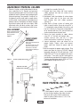
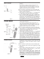
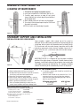
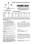
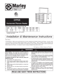
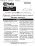
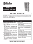
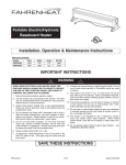
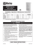
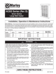
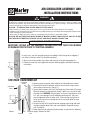
AIR CIRCULATOR ASSEMBLY AND
INSTALLATION INSTRUCTIONS
!
WARNING
Read Carefully – This instruction sheet contains vital information for the proper installation, use, and efficient operation of the
fan described. Carefully read this manual before installation, cleaning, or operation of the fan. Failure to adhere to the
instructions could result in fire, electrical shock, death, serious personal injury, or property damage. Save these instructions
and review frequently for continuing safe operation and instructing future users.
CAUTION – TO REDUCE RISK OF FIRE AND ELECTRIC SHOCK:
1. Before servicing or cleaning unit, unplug power to fan to prevent power from being switched on accidentally.
2. Installation work and electrical wiring must be done by qualified person(s) in accordance with all applicable codes and standards, including fire-rated construction.
3. When cutting or drilling into wall or ceiling, do not damage electrical wiring or other hidden utilities.
CAUTION: DO NOT MOVE FAN WHILE BLADE IS MOVING. ALWAYS TURN FAN OFF AND LET BLADE
STOP BEFORE ATTEMPTING TO MOVE. DO NOT USE BLADE GUARD TO MOVE FAN.
SAVE THESE INSTRUCTIONS
IMPORTANT: REVIEW ALL THE ASSEMBLY INSTRUCTIONS AND CHECK FOR MISSING
OR DAMAGED PARTS PRIOR TO STARTING ASSEMBLY.
In most cases, your fan head will come pre-assembled at the factory prior to shipping, if
not, follow instructions titled “Fan Head Unassembled”.
1. Remove fan head assembly from carton and check for missing or damaged parts.
2. Choose the mount for your application from the following pages, and follow mounting
instructions.
FAN HEAD UNASSEMBLED
FAN GUARD
FRONT
FAN GUARD
BACK
FLAT WASHERS
Figure 1
NUT
LOCK WASHER
1. Remove motor, fan guard (front and back) and fan blade from cartons.
2. Secure back half of fan guard to studs on face of motor using washers,
lock washers and hex nuts. (See fig. 1)
3. Secure blade to motor shaft, with hub facing away from motor (Discharge
Side) for commercial and industrial models. Tighten set screw to flat side
of motor shaft. WARNING: Do not tighten set screw to round side of shaft
as it will cause damage to shaft and blade could come off. Set screw
must be tightened to flat of motor shaft. Failure to align and tighten to
flat on shaft may result in damage to shaft or may allow blade to come
loose.(See fig. 1).
4. Secure front half of fan guard to back by hanging guard at top and working hooks together down sides and across bottom. Snap hook in place
with screwdriver.
5. Follow directions for mounting head assembly on mount on the following
pages (Pedestal or Wall).
FAN BLADE
HUB
ADJUSTABLE PEDESTAL COLUMN
1. Remove 2 sections of adjustable pedestal column
from carton(See fig. 2). Remove oval grommet
from parts package and install in oval slot near top
of pedestal column, Remove large round grommet
from parts package. Turn grommet “inside out” so
that groove is on the inside and the smooth side is
on the outside. Install grommet over bottom lip of
pedestal column. Feed power cord down through
top of black section (end with screw holes). Slide
adjustment collar into black section, align screw
holes and secure. Secure adjustment collar to low-
est height for assembly (See fig. 3).
2. Remove base from carton and insert medium
rubber grommet into hole on surface of fan
base.(See fig. 3)
3. Feed power cord from bottom of column down
through center hole of fan base and then
back through hole with rubber grommet.
(See fig. 3).
4. Align holes in flange at base of column with
holes in top of fan base. Secure by using 5/16” x
1” carriage bolts, external tooth star washers, and
hex nuts. (See fig. 3). One of the carriage bolts is
to be attached with the 5/16” internal tooth star
washer mounted under the bolt head.
5. Secure fan head assembly to upper column
using 1/2” x 1” hex bolt, star washers, lock
washers and hex nuts; and 1/4” x 1” bolt,
washer, lock washers, and hex nut. (See fig. 4).
6. Loosen adjustment collar and extend fan to
proper height. Tighten collar and connect
power cord from column to power cord on
motor.
7. Refer to nameplate for proper supply voltage. Plug
power cord from fan into any 120 VAC 3-prong
grounded outlet for all 120 volt rated units. Units
rated 220V or 277V are not supplied with attachment plugs. These units may be hard wired to a
junction box or provided with the required 15 amp,
3 prong grounded plug rated at 250V or 277V as
per nameplate rating of the fan unit.
OVAL GROMMET
Remove oval grommet from parts
package and install in oval slot
near top of pedestal
Figure 2
LARGE ROUND
GROMMET
Remove large round grommet from
parts package.
Turn grommet “inside out” so that
groove is on the inside and the
smooth side is on the outside.
Install grommet over bottom lip of
pedestal column.
Figure 3
Remove 2 phillips head screws.
RUBBER
GROMMET
Align and secure with
2 phillips head screws.
Figure 4
FIXED PEDESTAL COLUMN
1. If fixed pedestal column comes un-assembled,
put two sections together, align holes at union,
and secure with screws. Power cord for this
model is external. Follow items 2, 4, 5 & 7 for
balance of installation.
Figure 5
2
1. Securely attach wall mount to either a wood or concrete wall.
(See fig. 7)
WALL MOUNT
For installation on wood construction (minimum of 2” x 4”
stud), secure bracket with heavy duty lag bolts or screws (not
included). For concrete or masonry installation use heavy duty
expansion shields and lag screws (not included).
NOTE: All installations should be done to meet local building code.
2. Attach swivel mounting plate to end of bracket using 1/2” bolt, lock
washers, and hex nut. (See fig. 7)
3. Secure motor to wall mount using 1/2” x 1” hex bolt and 1/4”
x 1” bolt, washers, lock washers, and hex nuts. (See fig. 8)
4. Refer to nameplate for proper supply voltage. Plug power cord
from fan into any 120 VAC 3-prong grounded outlet for all 120
volt rated units. Units rated 220V or 277V are not supplied with
attachment plugs. These units may be hard wired to a junction
box or provided with the required 15 amp, 3 prong grounded plug
rated at 250V or 277V as per nameplate rating of the fan unit.
Figure 7
Figure 8
1. Securely attach ceiling mounting plate to either a wood or
concrete ceiling. (See fig. 9)
CEILING MOUNT
For installation on wood construction (minimum of 2” x 4”
stud), secure bracket with heavy duty lag bolts or screws (not
included). For concrete or masonry installation use heavy duty
expansion shields and lag screws (not included).
(Not Included)
NOTE: All installations should be done to meet local building code.
2. Screw section of 1 1/2” pipe (Installer furnished, and threaded
on both ends) into mounting plate. Then screw fan head
mounting section onto pipe. (See fig. 10)
3. Secure motor to ceiling mount using 1/2” x 1“ hex bolt and
1/4” x 1” bolt, washers, lock washers & hex nuts. (See fig. 11)
4. Refer to nameplate for proper supply voltage. Plug power cord
from fan into any 120 VAC 3-prong grounded outlet for all 120
volt rated units. Units rated 220V or 277V are not supplied with
attachment plugs. These units may be hard wired to a junction
box or provided with the required 15 amp, 3 prong grounded
plug rated at 250V or 277V as per nameplate rating of the fan unit.
Figure 9
Figure 10
Figure 11
1. Place two U-bolt I-beam clamps on threaded pipe - Position
threaded pipe on either horizontal or vertical I-beam and slide
U-bolt firmly on I-beam and tighten securely to beam.
(See fig. 12)
I-BEAM MOUNT
NOTE:All installations should be done to meet local building codes.
Figure 12
Figure 13
2. Screw mounting section securely onto threaded end of pipe
(See fig. 12)
3. Secure motor to I-beam mount using 1/2” x 1” hex bolt,
washers, lock washers, and hex nuts; and 1/4” x 1” bolt, washer,
lock washers and hex nut. (See fig. 13)
4. Refer to nameplate for proper supply voltage. Plug power cord
from fan into any 120 VAC 3-prong grounded outlet for all 120
volt rated units. Units rated 220V or 277V are not supplied with
attachment plugs. These units may be hard wired to a junction
box or provided with the required 15 amp, 3 prong grounded plug
rated at 250V or 277V as per nameplate rating of the fan unit.
3
REMOVAL OF FRONT GUARD FOR
CLEANING OR MAINTENANCE
1. Turn off fan and unplug from power source!
2. Insert two screwdrivers as illustrated. (See fig. 14)
3. Carefully apply pressure on edge of rear guard
inward and pressure to front edge of guard outward
to disengage hook.
4. Work around guard until all hooks are disengaged.
5. To re-attach front of guard repeat step 3 of Fan Guard
Assembly instructions.
NOTE: Be careful not to bend edge of guards.
Figure 14
SECONDARY SUPPORT CABLE INSTALLATION
FOR WALL/CEILING AND I-BEAM MOUNTS
Loop secondary support cable around top of fan guard as
indicated. Secure cable making sure both front and back guards are
inside loop, but that cable is not allowed to touch fan blade (See fig.
15). Secure ends with two cable clamps, loop other end of cable
around any permanent sturdy structural member close to fan (Ibeam, rafter, joist, etc...) and secure ends with two cable clamps.
Figure 16
IMPORTANT NOTICE: It is important to note the proper installation
position of the cable clamps as illustrated. To obtain maximum holding power, install U-bolt section of clip on dead or short end of cable
and saddle on long end of cable(See fig. 16). Improper installation
reduces the efficiency of the connection by as much as 40 percent.
Figure 15
GENERAL SAFETY INFORMATION
8. A secondary support cable should be used with any
overhead installation.
9. Extension cords should not be used with fans. If it is
necessary to use one, use only three wire extension
cords with three prong grounded type plugs. Refer to
table for correct wire size.
1. Always unplug power cord when servicing fan.
2. To reduce the risk of fire or electric shock do not use this
fan with any solid state motor speed control.
3. Never allow fan to become wet or damp.
4. Never move or adjust fan height while fan is running.
5. Never put fingers or foreign objects through fan guard.
6. Motor is permanently lubricated - do not oil.
7. Check all hardware periodically to make sure all is
secure. Loose hardware could cause damage to fan.
EXTENSION CORD LENGTH
UP TO 25 FEET
25-50 FEET
WIRE SIZE AWG
14
12
HOW TO OBTAIN WARRANTY SERVICE AND
WARRANTY PARTS PLUS GENERAL INFORMATION
1. Warranty Service or Parts
2. Purchase Replacement Parts
3. General Product Information
1-800-642-4328
1-800-654-3545
www.marleymep.com
470 Beauty Spot Rd. East
Bennettsville, SC 29512 USA
Note: When obtaining service always have the following:
1. Model number of the product
2. Date of manufacture
3. Part number or description
ECR 37011
Part No. 5200-2391-003
02/07
4