1
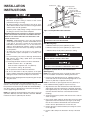
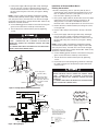
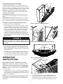
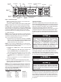
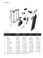
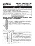
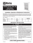
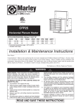
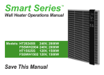
ARWH Series
Smart Series
Architectural Wall Heater
Installation, Operation & Maintenance Instructions
Table 1. Specifications
MODEL
ARWH1802
ARWH4808
ARWH4804
ARWH4807
VOLTS
PHASE
WATTS
AMPS
MIN. SUPPLY
WIRE GAUGE
120
208
240
277
1
1
1
1
540-1800
1440-4800
1440-4800
1440-4800
15
23.1
20.0
17.3
12
10
10
12
NOTE: The model numbers shown are Northern White color. Add suffix to the model number for the following colors:
AL = Aluminum, BZ = Bronze, W = Navajo White.
IMPORTANT INSTRUCTIONS
WARNING
WHEN USING ELECTRIC APPLIANCES, BASIC PRECAUTIONS SHOULD ALWAYS BE FOLLOWED TO REDUCE THE
RISK OF FIRE, ELECTRIC SHOCK, AND INJURY TO PERSONS, INCLUDING THE FOLLOWING:
1. Read all instructions before installing or using this heater.
2. This heater is hot when in use. To avoid burns, do not let
bare skin touch hot surfaces. Keep combustible materials,
such as furniture, pillows, bedding, papers, clothes, etc. and
curtains at least 3 feet (0.9 m) from the front of the heater.
3. Extreme caution is necessary when any heater is used by or
near children or invalids and whenever the heater is left
operating and unattended.
!
10. Use this heater only as described in this manual. Any other
use not recommended by the manufacturer may cause fire,
electric shock, or injury to persons.
11. This heater is provided with a red alarm light that will illuminate only if the heater has turned off as a result of overheating. Should the sensor register an overheat condition,
the heater will stop generating heat and the fan will turn off.
The red alarm light will turn ON, and ALL BUTTONS WILL
BE DISABLED. Once the heater is safe for resetting, the red
alarm light will blink/flash. DO NOT OPERATE THE
HEATER WITH THE ALARM LIGHT ILLUMINATED. See
TO RESET THERMAL LIMIT CONTROL in OPERATING
INSTRUCTIONS section.
5. Do not use outdoors.
12. This heater is intended for comfort heating applications and
not intended for use in special environments. Do not use in
damp or wet locations such as marine or greenhouse or in
areas where corrosive or chemical agents are present.
6. To disconnect heater, turn controls to OFF, and turn OFF
power to heater circuit at main disconnect panel.
13. When installing, see INSTALLATION INSTRUCTIONS for
additional warnings and precautions.
7.
14. For safe and efficient operation, and to extend the life of your
heater, keep your heater clean - See MAINTENANCE
INSTRUCTIONS.
4. Do not operate any heater after it malfunctions. Disconnect
power at service panel and have heater inspected by a reputable electrician before using.
Do not insert or allow foreign objects to enter any ventilation
or exhaust opening as this may cause an electric shock, fire,
or damage to the heater.
8. To prevent a possible fire, do not block air intake or exhaust
in any manner.
9. A heater has hot and arcing or sparking parts inside. Do not
use it in areas where gasoline, paint, or flammable liquids
are used or stored.
SAVE THESE INSTRUCTIONS
ECR 39603
11/12
5200-11074-001
INSTALLATION
INSTRUCTIONS
Ground screw
Cable
clamp
Power supply cable
Lead wires (Blue)
Disconnect switch
bracket with switch and
leads
(No disconnect
switch on
208V models)
12” Min.
(305 mm)
To prevent a possible fire, injury to persons or damage to the
heater, adhere to the following:
Back Box
1. Disconnect all power coming to heater at main service
panel before wiring or servicing.
12” Min.
(305 mm)
2. All wiring procedures and connections must be in accordance with the National and Local Codes having jurisdiction
and the heater must be grounded.
3. Verify the power supply voltage coming to heater matches
the ratings as shown on the heater nameplate.
Nail or screw
(2 each side)
Figure 1: Locating Back Box in New Construction
Mounting Clearances
CAUTION: ENERGIZING HEATER AT A VOLTAGE GREATER
THAN THE VOLTAGE PRINTED ON THE NAMEPLATE WILL
DAMAGE THE HEATER AND VOID THE WARRANTY AND
COULD CAUSE A FIRE.
TO PROVIDE FOR SAFE OPERATION, THE FOLLOWING
CLEARANCES MUST BE MAINTAINED.
4. CAUTION - High temperature, risk of fire, keep electrical
cords, drapery, furnishings, and other combustibles at least
3 feet (0.9 m) from front of heater. Do not install heater
behind doors, below towel racks, or in an area where it is
subject to being blocked by furniture, curtains or storage
materials. Hot air from the heater may damage certain fabrics and plastics.
Wall Mounting Only:
a. Minimum twelve (12) inches (305 mm) to floor;
b. Minimum twelve (12) inches (305 mm) to adjacent walls;
c. Minimum thirty six (36) inches (915 mm) to ceiling.
5. To reduce the risk of fire, do not store or use gasoline or
other flammable vapors and liquids in the vicinity of the
heater.
6. For wall mounting only with air discharge downward. Do
NOT install in floor, ceiling, upside down (air discharge
upward), or sideways.
TO PREVENT HAZARD OF FIRE OR ELECTRICAL SHOCK,
DO NOT INSTALL WITHOUT BACK BOX.
7. The following minimum clearances must be maintained:
Bottom of heater to floor - 12” (305 mm).
TO PREVENT POSSIBLE DAMAGE TO POWER WIRING,
USE ONLY THE KNOCKOUTS PROVIDED IN BACK BOX.
Sides of heater to adjacent wall - 12” (305 mm).
Top of heater to ceiling - 36” (915 mm).
Installation of Back Box in New Construction
(See Figure 1).
8. Do not operate the heater without the back box.
9. Do not use this heater for dry out purposes as the paint,
plaster, sawdust and drywall sanding dust will permanently
damage the heater and must be kept out of the heater.
NOTE: If the finished wall surface is already up, follow instructions for “Installation of Back Box in Existing Construction”.
10. Remove motor shipping bracket and yellow tag prior to operating this heater.
1. Place the back box between two 16" (406 mm) center-tocenter wall studs at the desired mounting height but no closer than 12" (305 mm) to adjacent wall or floor.
NOTE: If wall studs are spaced greater than 16” (407 mm) on
center, additional framing supports may be necessary.
The heater is designed for recessed installation in 2” x 4”
(50 mm x 101 mm) studs or larger wall sections using the back
box provided. The heater may be wired with standard building
wire (60°C). Refer to “Specifications” and heater nameplate for
correct supply voltage and wire size.
2. Align back box such that the bottom and sides will be flush
with finished wall surface (top flange of back box should protrude approximately 1/2" (12.7 mm) from finished wall surface
(You must know the thickness of the finished wall when
installing).
NOTE: The optimum mounting height for this heater is 18” to 24”
(450 mm to 600 mm) from floor to bottom of back box. DO NOT
install closer than 12” (305 mm) from the floor.
3. Secure the back box in position with wood screws or nails as
shown in Figure 1.
4. Run a power supply cable into the knockout area in the upper
right hand corner of the back box (see Figure 1). All wiring
must be in accordance with National and Local Electrical
Codes. Refer to Specifications for correct wire size.
5. Remove disconnect switch bracket by loosening two screws
on the right side.
6. Install a cable clamp in the knockout in the top of the back
box.
2
7. Insert power supply cable through cable clamp, allowing at
least 6" (152 mm) of leads to extend inside the back box.
Connect the blue lead wires of disconnect switch to the supply wire leads using wire connectors (see Figure 4, Wiring
Diagram).
Installation of Recessed Back Box in
Existing Construction
1. Provide a wall opening 14-3/4" (375 mm) wide by 18-1/2"
(470 mm) high at the desired mounting height, but no closer
than 12" (305 mm) from floor. (See Figure 2.) Locate so at
least one side of opening is at wall stud.
NOTE: If power supply is provided by standard non-metallic
sheathed cable (Romex) and the supply voltage is 240 or 208
volts (two power wires), the white wire color must be changed
using black electrical tape to comply with the NEC. White is only
allowed for a Neutral conductor.
2. Run a power supply cable into the knockout area in the upper
right hand corner of the wall opening (see Figure 2). All
wiring must be in accordance with National and Local
Electrical Codes. Refer to Specifications for correct wire size.
8. Connect building ground conductor to the back box using the
green screw located in the inside top of the back box.
3. Remove disconnect switch bracket by loosening two screws
on the right side.
9. Secure disconnect switch bracket in place by tightening
screws.
4. Install a cable clamp in the knockout in the top of the back
box.
5. Insert power supply cable through cable clamp, allowing at
least 6" (152 mm) of leads to extend inside the back box.
Connect the blue lead wires of disconnect switch to the supply wire leads using wire connectors (see Figure 4, Wiring
Diagram).
POWER SUPPLY VOLTAGE MUST BE THE SAME AS
HEATER VOLTAGE RATING SHOWN ON HEATER NAMEPLATE. CONNECTING TO A VOLTAGE IN EXCESS OF
NAMEPLATE RATING WILL DAMAGE HEATER AND VOID
WARRANTY.
ALL CONNECTIONS MUST BE MADE WITH APPROPRIATELY
SIZED LISTED WIRE CONNECTORS.
NOTE: If power supply is provided by standard non-metallic
sheathed cable (Romex) and the supply voltage is 240 or 208
volts (two power wires), the white wire color must be changed
using black electrical tape to comply with the NEC. White is only
allowed for a Neutral conductor.
6. Connect building ground conductor to the back box using the
green screw located in the inside top of the back box.
7.
Secure disconnect switch bracket in place by tightening
screws.
8. Insert back box in wall opening being careful not to damage
the supply wiring. Secure the back box in place with wood
screws or nails.
12” Min.
(305 mm)
12” Min.
(305 mm) Cable
clamp
Ground
14 1/2” Min.
screw
(362 mm)
Power supply cable
POWER SUPPLY VOLTAGE MUST BE THE SAME AS
HEATER VOLTAGE RATING SHOWN ON HEATER NAMEPLATE. CONNECTING TO A VOLTAGE IN EXCESS OF
NAMEPLATE RATING WILL DAMAGE HEATER AND VOID
WARRANTY.
ALL CONNECTIONS MUST BE MADE WITH APPROPRIATELY
SIZED LISTED WIRE CONNECTORS.
Lead wires (Blue)
Disconnect switch
bracket with switch
and leads. (No disconnect switch on 208V
models)
Back Box
Nail or screw
(2 each side)
Figure 2: Locating Back Box in Existing Construction
G
L/N
*BLK
*BLU
GRN
L/N
J4
GRN
GRN
J3
L1
L1
BLK
(ON GRILL)
G1
DISCONNECT SWITCH
(PROVIDED ON ALL MODELS
EXCEPT 208V/1P UNITS)
G2
J2
D
E
EOL
LIMIT
SWITCH
J1
J-JUMPER
B
TRIAC-N
C
A
B
2
3
4
1
ELEMENT WIRING FOR 4800W, 208V/1PH
E1
FAN-N
Transformer
R1
HIGH
MOTOR
RED JUMPER WIRE FOR
BUILDING MANAGEMENT
SYSTEM CONNECTION
R2
POWER BOARD
RL-4
BMS
B
TRIAC-LL
ELEMENT
OVERHEAT
THERMISTOR
DATA CABLE
V2
DISPLAY BOARD
INFRARED
RECEIVER
A
NOTES:
1. WIRES “C”, “E” AND JUMPER “J” ARE
SUPPLIED SOLDERED TO THE PC BOARD.
2. *BLK AND *BLU LEAD WIRES ARE IDENTIFIED
WITH WHITE TAPE AT EACH STRIPPED ENDS
TO INDICATE THAT THE NEUTRAL FOR THE
120V AND 277V MODELS ARE TO BE
CONNECTED TO THESE LEADS.
TRIAC
REGULATING
THERMISTOR
POWER
LIGHT
BLK
V1
WHT
YEL
G
ELEMENT
LOW
OVERHEAT
LIGHT (see page 5)
LEGEND
EOL
BMS
G1, G2
J
R1, R2
Figure 3- Wiring Diagram
3
END OF LIFE SWITCH
BUILDING MANAGEMENT SYSTEM
GROUND SCREWS
JUMPER
MANUAL RESET RELAY
FIELD WIRING
J5
A
ELEMENT WIRING FOR 4800W, 240V/1PH, 277V/1PH
& 1800W 120V/1PH
Building Management Systems (BMS)
Control
Shelf
To utilize the BMS capabilities of this unit, remove the red
jumper wire between terminals A and B on the control terminal
board ( see figure 3, wiring diagram). Connect two wires from a
dry contact (no voltage) in the BMS system to terminals A and B.
Notches
NOTE: DO NOT REMOVE THE RED JUMPER UNLESS
THE UNIT IS BEING CONTROLLED BY A BUILDING MANAGEMENT SYSTEM (BMS).
When BMS takes control, heater functions will not work, the
touch screen is locked, BMS light on the heater touchscreen
blinks.
When BMS releases control, heater functions are available,
heater resumes operating at previously programmed settings.
Refer to Operations Manual for programming options and details.
Installation of Grille and Control Wire Connector
Figure 4- Installation of Heater/Grille Assembly
1. Push disconnect switch into ON position.
2. Position the grille in front of the heater assembly, insert the
control shelf edges into the notches on either side of the
back box at the same time hooking the tabs on the bottom
corners of the grille assembly over the bottom flange of the
back box (see Figures 4 and 5). With the top of the grille
assembly leaning forward, supported by the first notch in
control shelf, extend the control wires from the back of the
electronic control at the top of the grille and connect to the
wires of the disconnect switch assembly according to Wiring
Diagram Figure 3.
Back Box
Notch
Tab
Control
Shelf
THE HEATER ASSEMBLY MUST BE CAREFULLY POSITIONED TO ENSURE THE CONTROL WIRES ARE NOT
TRAPPED BETWEEN THE HEATER ASSEMBLY AND THE
BACK BOX.
Flange
Figure 5- Grille Assembly Detail, Grille Supported for Wiring
3. Lift and rotate the the grille assembly into the backbox carefully to ensure the control wire is not trapped between the
grille assembly and back box. Insert two screws at the top
edge of grille assembly on either side of the control panel as
shown in Figure 6.
Screw Locations
4. Install (2) plastic bezels (left and right) on either side of the
control panel by inserting the wide tab under the flange on
the control panel as shown in Figure 7, rotating the narrow
end down and pressing firmly so the clip snaps into place.
OPERATION
INSTRUCTIONS
Figure 6- Securing Grille Assembly
Plastic Bezel
Initial Setup Instructions (Performed by Installer)
Tab Under Flange
of Control Panel
Clip
NOTE: After installation, the installer should perform the following procedures to ensure proper operation of the heater (see
Figure 8 for Control Panel Layout). Refer to the OPERATIONS
MANUAL for details on programming and activating other features of the heater.
1. Turn ON power to the unit at the main service panel. When
the heating unit is first powered up, it will default to ON. The
green power indicator LED will illuminate as long as there is
power to the heating unit.
Figure 7- Securing Plastic Bezel
2 If the heating unit is OFF, touch the POWER button to turn
the unit ON (The display is a touch screen and does not
respond to pressure). The display should illuminate showing
the current room temperature and default program number,
NOTE: If the unit does not beep and the display does not light,
turn off power at the main service panel and check that the
Control Wire is connected and the Disconnect Switch is in the
ON position.
4
Fan Speed
Indicator
Day Indicator
Time
Periods
Time
Temperature
Centigrade / Fahrenheit
Indicator
Mode Button
Up Button
Heat Control
Indicator
Night Light
Indicator
Lockout
Indicator
Automatic Mode
Indicator
Hold Mode
Indicator
Building Management
System indicator
Power Button
Down Button
Figure 8 - Control Panel Layout
Operational Notice
AUTO icon and time. If the screen is in the activated state,
and no buttons are touched for 30
seconds the display backlight will turn OFF (standby mode).
This heater is equipped with a manual reset thermal limit control
that will automatically turn OFF the heater if it overheats to prevent
a fire. A red warning light will illuminate, error code and overheat
temperature will flash on the display, and an audible alarm (beep)
will sound to alert that this control has activated (see
Troubleshooting under Maintenance for a list of error codes). Once
activated the heater will turn OFF and the display will lock. Once
the unit has cooled to a normal operating temperature the display
will unlock and the user will be able to reset the thermal limit control.
NOTE: If heating unit is in the stand by mode (where display
backlight is OFF), touching any button will illuminate the backlight and display operating buttons. Touching the POWER button
when the heater is in stand by mode will illuminate the backlight,
touching the POWER button again will turn the heater OFF.
Please note power is live to heating unit when the unit is OFF.
3. Set Day and Time:
NOTE: For the following setup procedures, the display will automatically save the setting after a 30 second pause and return to
the previous operating setting. If this occurs, start back at
Step a of the Set Day and Time procedure.
THE ACTIVATION OF THE THERMAL LIMIT CONTROL AND
RED WARNING LIGHT OCCURS WHEN THE HEATER OVERHEATS. CHECK HEATER TO MAKE SURE IT IS NOT
BLOCKED – IF SO, REMOVE THE BLOCKAGE. IF THERE IS
NO BLOCKAGE, IT IS RECOMMENDED THAT THE HEATER
BE INSPECTED BY A REPUTABLE ELECTRICIAN OR
REPAIR SERVICE TO ENSURE THE HEATER IS NOT
DAMAGED. DO NOT CONTINUE TO USE HEATER IF IT
REPEATEDLY CYCLES OFF ON THIS THERMAL LIMIT.
a. Simultaneously touch and hold the UP button and DOWN
button for 1.5 seconds. A beep will sound and the Day indicator at the top of the display will flash (the buttons on the
display respond to touch, not pressure).
NOTE: If user touches the POWER button at any point during
setup procedure, the display will automatically save settings and
return to the previous operating setting.
b. Using the UP or DOWN buttons, adjust to appropriate DAY
of week.
TO RESET THERMAL LIMIT CONTROL
After the unit has cooled to a safe operating temperature, the red
warning light will begin to flash, and the display will become
active. The heater is now ready to be reset. In order to reset the
thermal limit control, press the POWER and UP buttons and hold
for 1.5 seconds, the unit will return to normal operation.
c. Touch the MODE button. AM / PM indicator will flash. Use
the UP and DOWN buttons to set appropriate time.
AM / PM will change automatically once you pass 12:00.
d. Touch the MODE button, MINUTES will flash. Use the UP
and DOWN buttons to set MINUTES to the appropriate
time.
e. After the last parameter is set, touch the MODE button to
lock in your settings.
DO NOT TAMPER WITH OR BYPASS ANY THERMAL LIMITS
INSIDE HEATER.
4. Once the installer has performed the initial setup, power
down the unit by touching the POWER button if no other programming will be done at this time.
NOTE: The unit is programmed with default time and temperature settings for the Automatic Mode (see below). If these settings are satisfactory, then no other programming needs to be
done. Refer to the OPERATIONS MANUAL for instructions on
other useful options and features.
CAUTION - DO NOT CONTINUE TO ATTEMPT TO USE THE
HEATER IF THE THERMAL LIMIT CONTROL REPEATEDLY
OPERATES AFTER BEING RESET. TO DO SO COULD PERMANENTLY DAMAGE THE HEATER OR CREATE A FIRE OR
SAFETY HAZARD.
Default settings for Automatic Mode:
Period
Time
Setpoint
1. Wake Up
6:00 AM
70°F (21°C)
2. Daytime
8: 00 AM
62°F (17°C)
3. Evening
6:00 PM
70°F (21°C)
4. Sleep Time
10:00 PM
62°F (17°C)
NOTE: The unit is provided with an End of Life “oneshot” protective device. This serves as a back up protector in extreme conditions when the electronic overheat protector fails during an overheat condition. If the protector opens (no light or sound on the
display controller) and the power is connected and the unit does
not come ON, the the heater is no longer functional and has to
be replaced.
5
MAINTENANCE
INSTRUCTIONS
Error Codes
In the event of overheating or other malfunction the heater will
display one of the error codes below:
E1
E1 is displayed if the regulating thermistor is
OPEN. A red warning light will illuminate, the
alarm will beep 10 times and E1 will continue to
flash on the display. The user should disconnect
power at the main circuit panel and call
Technical Support: 800-642-4328.
ALL SERVICING BEYOND SIMPLE CLEANING THAT
REQUIRES DISASSEMBLY SHOULD BE PERFORMED BY
QUALIFIED SERVICE PERSONNEL.
E2
E2 will be displayed if the regulating thermistor has
malfunctioned. A red warning light will illuminate,
the alarm will beep 10 times and E2 will continue
to flash on the display. The user should disconnect
power at the main circuit panel and call
Technical Support: 800-642-4328.
TO REDUCE RISK OF FIRE AND ELECTRIC SHOCK OR
INJURY, DISCONNECT ALL POWER COMING TO HEATER
AT MAIN SERVICE PANEL AND CHECK THAT THE ELEMENT
IS COOL BEFORE SERVICING OR PERFORMING
MAINTENANCE.
ES
ES will be displayed if the Thermal Limit Control
has malfunctioned. A red warning light will illuminate, the alarm will beep 10 times and ES will continue to flash on the display. The user should disconnect power at the main circuit panel and call
Technical Support: 800-642-4328.
ES/Temp
ES/Temperature will toggle back and forth on the
display if there is an overheat condition. A red
warning light will illuminate, the alarm will beep 10
times and ES/Temperature will continue to flash on
the display. See To Reset Thermal Limit Control on
page 5.
It is important to keep this heater clean. Your heater will give you
years of service and comfort with only minimum care. To assure
efficient operation follow the simple instructions below.
User Cleaning Instructions:
1. After the heater has cooled, a vacuum cleaner with brush
attachment may be used to remove dust and lint from exterior
surfaces of the heater including the grille openings.
2. With a damp cloth, wipe dust and lint from grille and exterior
surfaces.
ES (E1/E2) ES will toggle back and forth with E1/E2 on the
display if there is a malfunction with one of the
thermistors. A red warning light will illuminate, the
alarm will beep 10 times and ES and E1/E2 will
continue to flash on the display. The user should
disconnect power at the main circuit panel and call
Technical Support: 800-642-4328.
3. Return power to heater and check to make sure it is operating properly.
Maintenance Cleaning Instructions:
(To be performed only by Qualified Service Personnel)
At least annually, the heater should be cleaned and serviced by
a qualified service person to assure safe and efficient operation.
This should include the removal of the grille/heater assembly as
necessary from the backbox to clean residue from the unit. After
completing the cleaning and servicing, the heater should be fully
reassembled and checked for proper operation.
6
REPAIR PARTS
9
5
8
7
6
1
2
4
10
16
13
11
3
12
Repair Parts List
Ref
Part Number
No
Description
ARWH4804
ARWH4808
ARWH4807
ARWH1802
1
Grille
2501-11019-VAR*
2501-11019-VAR*
2501-11019-VAR*
2501-11019-VAR*
2
Motor
3900-11026-000
3900-11026-000
3900-11026-001
3900-11026-002
3
Element
302012810
1802-2075-801
302012811
302012828
4
Fan Blade
490030103
490030103
490030103
490030103
5
Right Bezel
1219-11009-001
1219-11009-001
1219-11009-001
1219-11009-001
6
Left Bezel
1219-11009-000
1219-11009-000
1219-11009-000
1219-11009-000
7
Disconnect Switch
410170001
N/A
410170001
410170001
8
Control Power Board
1414-11033-000
1414-11033-000
1414-11033-001
1414-11033-002
9
Display Bezel
1016-11188-000
1016-11188-000
1016-11188-000
1016-11188-000
10
Thermistor
5262-11007-000
5262-11007-000
5262-11007-000
5262-11007-000
11
Over Heat Sensor
5262-11009-000
5262-11009-000
5262-11009-000
5262-11009-000
12
Grille Bracket Left
1215-11070-000
1215-11070-000
1215-11070-000
1215-11070-000
13
Grille Bracket Right
1215-11070-001
1215-11070-001
1215-11070-001
1215-11070-001
14
Remote (not shown)
1414-11037-000
1414-11037-000
1414-11037-000
1414-11037-000
15
Parts Kit (not shown)
1205-11023-000
1205-11023-000
1205-11023-000
1205-11023-000
16
Element Bracket
1215-11090-000
1215-11090-000
1215-11090-000
1215-11090-000
*NOTE: The standard color is Northern White. Add suffix to the model number for the following colors:
AL = Aluminum, BZ = Bronze, W = Navajo White. Call Factory for part number.
7
LIMITED WARRANTY
All products manufactured by Marley Engineered Products are warranted against defects in workmanship and materials for one year from date of installation, except
heating elements which are warranted against defects in workmanship and materials for five years from date of installation. This warranty does not apply to damage from
accident, misuse, or alteration; nor where the connected voltage is more than 5% above the nameplate voltage; nor to equipment improperly installed or wired or
maintained in violation of the product’s installation instructions. All claims for warranty work must be accompanied by proof of the date of installation.
The customer shall be responsible for all costs incurred in the removal or reinstallation of products, including labor costs, and shipping costs incurred to return products to
Marley Engineered Products Service Center. Within the limitations of this warranty, inoperative units should be returned to the nearest Marley authorized service center
or the Marley Engineered Products Service Center, and we will repair or replace, at our option, at no charge to you with return freight paid by Marley. It is agreed that such
repair or replacement is the exclusive remedy available from Marley Engineered Products.
THE ABOVE WARRANTIES ARE IN LIEU OF ALL OTHER WARRANTIES EXPRESSED OR IMPLIED, AND ALL IMPLIED WARRANTIES OF MERCHANTABILITY AND
FITNESS FOR A PARTICULAR PURPOSE WHICH EXCEED THE AFORESAID EXPRESSED WARRANTIES ARE HEREBY DISCLAIMED AND EXCLUDED FROM THIS
AGREEMENT. MARLEY ENGINEERED PRODUCTS SHALL NOT BE LIABLE FOR CONSEQUENTIAL DAMAGES ARISING WITH RESPECT TO THE
PRODUCT, WHETHER BASED UPON NEGLIGENCE, TORT, STRICT LIABILITY, OR CONTRACT.
Some states do not allow the exclusion or limitation of incidental or consequential damages, so the above exclusion or limitation may not apply to you. This warranty gives
you specific legal rights, and you may also have other rights which vary from state to state.
For the address of your nearest authorized service center, contact Marley Engineered Products in Bennettsville, SC, at 1-800-642-4328. Merchandise returned to the factory must be accompanied by a return authorization and service identification tag, both available from Marley Engineered Products. When requesting return authorization,
include all catalog numbers shown on the products.
HOW TO OBTAIN WARRANTY SERVICE AND
WARRANTY PARTS PLUS GENERAL INFORMATION
1. Warranty Service or Parts
2. Purchase Replacement Parts
3. General Product Information
1-800-642-4328
1-800-654-3545
www.marleymep.com
Note: When obtaining service always have the following:
1. Model number of the product
2. Date of manufacture
3. Part number or description
470 Beauty Spot Rd. East
Bennettsville, SC 29512 USA