1
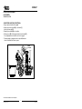
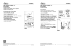
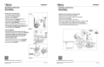
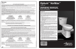
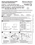
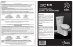
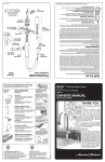
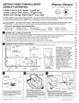
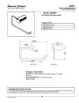
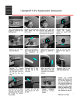
VORMAX™
VORMAX™
flush valve assembly
PART NUMBER:
7381422-100.0070A
PART NUMBER:
7381422-100.0070A
• All trim components including tank-to-bowl
gaskets, washers, nuts, clevis pin, and hair pin
• Includes a nut tightening tool
Removal:
• Turn off water supply; flush toilet
(remove all water from the tank)
• Remove tank nuts (Do not remove 2nd set
of tank nuts) FIGURE 1 & 2
• Remove tank from bowl & lay tank on flat surface
on backside to prevent scratching
(No need to remove trip lever)
• Remove hair pin FIGURE 3
• Remove clevis pin; this frees the teeter bar from
the trip lever arm FIGURE 3
• Remove the refill tube clip from the overflow tube
• Grab and remove tank to bowl gaskets from the
underside of the tank
• Take the included tool and remove the tank to bowl
nut counterclockwise
• Remove friction washer
• Remove flush valve assembly from the inside
through the top of the tank
➞
FIGURE 1
DO NOT REMOVE NUTS
FIGURE 2
RE-assembly:
• Install the valve, orient valve assembly so overflow tube is
positioned towards the back of the tank FIGURE 4
• Hold the valve in the tank with one hand
• Place friction washer over threads on the bottom of
the tank FIGURE 5
•A
ttach nut FIGURE 6 (for orientation tabs must face
further away from tank)
•U
se supplied tool to tighten nuts to tank
(one hand tight)
•A
pply and work the gaskets around the 6 retaining
tabs on the nut so the inner rib on the gasket is
captured between the tabs and the tank. Note the
inner rib on the gasket is offset to one side. Be sure
to orient the gasket with the inner rib towards the tank.
When done correctly, the gasket should not be
compressed and should be held in place while
installing the tank
FIGURE 5
•R
e-mount tank to bowl
•R
eattach refill tube clip onto the overflow tube of the new valve
(hose should direct water into overflow tube)
• Insert the trip lever arm in to the yoke FIGURE 3
• Push the clevis pin through the arm FIGURE 3
• Insert the hair pin FIGURE 3
OVERFLOW
TUBE
➞
flush valve assembly
FIGURE 4
NUT &
GASKET
FIGURE 6
CLEVIS ➞
PIN
➞
HAIR
PIN
YOKE ➞
FIGURE 3
www.americanstandard-us.com/vormaxparts
www.americanstandard-us.com/vormaxparts
Product names listed herein are trademarks of AS America Inc.
© AS America Inc. 2014
1
7302171-100
Product names listed herein are trademarks of AS America Inc.
© AS America Inc. 2014
2
7302171-100
VORMAX™
flush valve assembly
PART NUMBER:
7381422-100.0070A
Complete by Adjusting the Settings:
• Depress trip lever handle all the way (A)
• Adjust screw on the teeter bar (B) so rear frame (C)
touches the frame stop (D)
• Return trip lever handle (A) to rest position.
• Make sure hook (E) is fully engaged under tab on valve body (F),
if not, slightly adjust screw to make sure hook is engaged.
• Turn water supply on; adjust water level to specified dimension
on back of tank and flush 5 times to prime
HOOK
CROCHET
(B)
(C)
(A)
(D)
(E)
(F)
www.americanstandard-us.com/vormaxparts
Product names listed herein are trademarks of AS America Inc.
© AS America Inc. 2014
3
7302171-100