1
OUTDOOR STORAGE
MODEL N° 60005
Co
py
OWNER’S MANUAL
Keep this Identification Number in case you must contact our Customer Service Department.
1
IMPORTANT! PLEASE READ BEFORE BEGINNING ASSEMBLY
Dear Valued Customer,
We would like to congratulate you on your purchase of a Lifetime© Outdoor Storage Shed! We are
confident that you have made the perfect choice and you will be very pleased with your new storage
solution.
Lifetime© Outdoor Storage is part of the family of products created and manufactured by Lifetime®
Products, Inc. Like all of our products, you can be assured that the quality of your Lifetime Outdoor
Storage Shed is the best in the world! And, we back that quality up by offering the best warranty in the
business – A 10-year warranty that fully covers the Shed!
py
All of our Sheds are built with the highest-quality steel and high-density polyethylene (HDPE) parts. The
design and construction of our steel-reinforced double-Wall Panels is second to none. All of our exposed
steel parts and gables are powder coated and we use high-density polyethylene plastic. What makes
polyethylene so special? It has superior strength and durability, and, it won’t crack or degrade outdoors.
So now that you know the quality you are getting in a Lifetime Outdoor Storage Shed, please take the
time to READ THIS INSTRUCTION MANUAL!
We have taken great care in providing the best possible form of instructions to help you put your new
Outdoor Storage Shed together. Before you get started, PLEASE read the following preparation tips to
help you get started!
We can assure you, your construction experience will be a lot more enjoyable if you do!
Co
PREPARATION TIPS:
s4HElRSTSTEPISSIMPLEx2%,!89OUHAVEMADEAGREATPURCHASEBUT2OMEWASNOTBUILTINA
day. Plan to spend a good part of your weekend putting together your fine Outdoor Storage Shed. Our
PHILOSOPHYISIFITCOMESTOGETHERQUICKLYANDEASILYITSURELYWILLCOMEAPARTQUICKLYANDEASILY9OUR
Lifetime© Outdoor Storage Shed will surely last a long, long time, if you are patient, and take all the time
necessary to put it together as we have instructed.
s'RABAFRIENDTOJOININONTHEFUN4HISISNOTAONEPERSONENDEAVOR7EHAVEFOUNDTHATNOTONLYWILL
things go smoother if you have two or more people participating in the construction of the Shed, but it
will go quicker as well. So, the more the merrier!
s-AKESUREYOUHAVEALLTHETOOLSNECESSARYFORCONSTRUCTINGYOURNEW3HED4HEREISAh4OOLS2E
quired For This Assembly” list on page five of this Owner’s Manual.
s4HEPLASTICPIECESOFYOUR3HEDMAYBECOMEDAMAGEDBYOVERTIGHTENINGTHESCREWS4OAVOIDTHIS
damage, we strongly recommend the use of a low-powered power screwdriver or a drill that has an
adjustable clutch that is set on a low-torque setting. If neither is available, use a hand screwdriver. If a
HANDSCREWDRIVERISALLYOUHAVETAKESEVERALBREAKSxYOURWRISTWILLNEEDIT
s9OUWILLALSONEEDTWOSMALLLADDERSWHENITCOMESTIMETODOTHEROOF
Instruction #1075853 C
5/26/2011
2
IMPORTANT! PLEASE READ BEFORE BEGINNING ASSEMBLY
s"EFOREBEGINNINGASSEMBLYREMOVETHE0ARTS,ISTFROMTHECENTEROFTHIS/WNERS-ANUALANDTAKEAN
inventory of the parts included with your Outdoor Storage Shed. Also, read through the entire instruction manual. It’s always a great practice to get a feel for the flow of the process and to familiarize yourself with the parts involved. But, try not to get ahead of yourself and start the process out of order.
s&/,,/74(%).3425#4)/.3)./2$%2%VERYTHINGGOESTOGETHERINACERTAINORDERANDWEHAVE
learned what that correct order should be. In our state-of-the-art research and testing facility, we have
painstakingly created these instructions. The order of construction is there for a reason, and some parts
simply will not fit if built out of order. Just follow along with the order in the instructions and everything
will fit together and things will go very smooth.
s9/523(%$-534"%"5),4/.!,%6%,352&!#%)FTHESPOTYOUHAVECHOSENTOPLACEYOUR
wonderful new Outdoor Storage Shed is not level, the Shed will not assemble correctly! We recommend
ACONCRETEPATIOAWOODPLATFORMORCREATINGAPADWITHPEAGRAVEL9OUR3HEDISMEANTTOLASTALIFE
time, so provide the proper foundation for it before you start to build.
s"EFOREYOUBUILDITMAKESUREYOUAREALLOWEDTOBUILDIT#ONSULTALLBUILDINGCODESASWELLASCITY
and county ordinances, to ensure that you do not require a building permit to construct your Outdoor
Storage Shed. Proper building permit documentation may be required in your neighborhood, and it
would be quite unfortunate to learn this after your Outdoor Storage Shed is already built!
Now that you’re ready to begin the construction of your wonderful new Outdoor Storage Shed, step
back, take a deep breath, get yourself a large cold beverage and enjoy yourself. We guarantee that after
spending the right amount of time in building your Shed, you will be able to enjoy it for years to come.
Thanks for choosing Lifetime©, and have fun!
ABOUT LIFETIME PRODUCTS, INC.
Lifetime Products, Inc., has applied innovation and cutting-edge technology in plastics and
metals to create a family of affordable lifestyle products that feature superior strength and
durability. The world’s leading manufacturer of folding tables and chairs, Lifetime was founded in 1986 as the maker of portable basketball systems that revolutionized the industry with
patented technology. With diverse offerings such as outdoor storage sheds and steel utility
trailers, Lifetime continues to develop innovative products that outfit the way you live.
Lifetime makes the things you need for the lifestyle you want. By innovating products in and
around the home, Lifetime simplifies your everyday life and enables you to get the most out
of your free time.
3
REGISTER YOUR LIFETIME PRODUCT TODAY!
There are benefits to registering your Lifetime product. With our new online product registration form, it’s fast and easy! Register with us at www.lifetime.com
and enjoy these great benefits:
s2ECEIVEEXCLUSIVEMONEYSAVINGOFFERSFROM"UY,IFETIMECOMOURONLINESTOREASWELLAS.%7PRODUCTNOTIlCATIONSANDSPECIALCLOSEOUT
promotions!
s)NTHEUNLIKELYEVENTOFAPRODUCTRECALLORSAFETYMODIlCATIONWEWILLNOTIFYYOU
s2EGISTERINGYOURPRODUCTGUARANTEESYOUWARRANTYSERVICE)FYOUDONOTREGISTERYOURPRODUCTYOURWARRANTYRIGHTSWILLNOTBEDIMINISHED
But you will need to provide a sales receipt to verify your product purchase date before warranty service will be provided.
LIFETIME’S PROMISE TO YOU:
Maintaining your privacy is our long-standing policy at Lifetime. And you can rest assured that Lifetime will not sell or provide your
personal data to other third parties, or allow them to use your personal data for their own purposes.
We invite you to read our privacy policy at www.lifetime.com
REGISTER today!
**U.S. and Canada customers ONLY**
IF ASSISTANCE IS NEEDED,
DO NOT CONTACT THE STORE!
CALL OUR CUSTOMER SERVICE DEPARTMENT at 1 (800) 225-3865
HOURS: 7:00 a.m. to 5:00 p.m. Monday through Friday (Mountain Standard Time)
**Call, or visit our Web site for Saturday hours**
**For customers outside the U.S. or Canada, please contact the store for assistance.**
SAFETY INSTRUCTIONS
FAILURE TO FOLLOW THESE WARNINGS MAY RESULT IN SERIOUS INJURY OR
PROPERTY DAMAGE AND WILL VOID WARRANTY.
To ensure safety, do not attempt to assemble this product without following the instructions carefully. Check entire box and inside all
packing material for parts and/or additional instruction material. Before beginning assembly, read the instructions and identify parts
using the hardware identifier and parts list in this document. Proper and complete assembly, use and supervision are essential to
reduce the risk of accident or injury.
s$ONOTUSEORSTOREHOTOBJECTSSUCHASGRILLSBLOWTORCHESWELDINGEQUIPMENTETCNEARTHEPRODUCT
s)FUSINGALADDERDURINGASSEMBLYUSEEXTREMECAUTION
s4WOCAPABLEADULTSAREREQUIREDFORASSEMBLY)TISALSORECOMMENDEDTHATATHIRDADULTFUNCTIONASANINSTRUCTIONREADER
Most injuries are caused by misuse and/or not following instructions. Use caution when using this product.
4
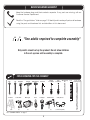
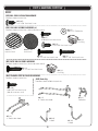
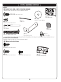
BEFORE BEGINNING ASSEMBLY
Keep the hardware bags and their contents separate. If any parts are missing, call our
Customer Service Department.
2EADTHEh#ONGRATULATIONSvLETTERONPAGEIdentify and inventory all parts and hardware
using the parts and hardware lists and identifiers in this document.
*Two adults required to complete assembly*
Only adults should set up the product. Do not allow children
in the set-up area until assembly is complete.
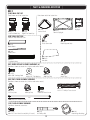
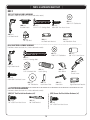
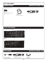
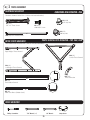
TOOLS REQUIRED FOR THIS ASSEMBLY
7/16"
3/8"
Adjustable
(2)
(1)
(1)
6’ Ladder
Power Drill*
Hammer
Rubber Mallet
(1)
(1)
Work Light
Pliers
Box Knife
(1)
Flashlight
Phillips
Screwdriver
(1)
Hammer Drill*
3/8" Masonry
Plain
Bit
Screwdriver
(1)
Level
2" x 4" x 8'
Leveling Board
(1)
Safety Glasses
(1)
(2)
(1)
(1)
(1)
(1)
(1)
*See “Screwdriver Notice” on page 7.
5
(1 for each person)
(1)
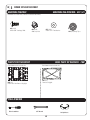
ASSEMBLY GUIDES
Refer to the following areas throughout the instructions
to assist in the assembly process:
This area is located at the top, left-hand
corner of the page and indicates which tools
and hardware are needed to complete the
assembly steps on a page.
TOOLS AND HARDWARE REQUIRED FOR THIS PAGE
SEC
This area is located at the top, right-hand
corner of the page and shows an image of the
product with shaded parts indicating which
section is being assembled.
This area is usually located in the bottom,
left-hand corner of a step and indicates that
special attention is needed to perform a
particular part of a step.
!
These areas are usually located in the bottom,
right-hand corner of a step and indicate that
damage to the product or serious injury may
occur if the caution or warning is not heeded.
Throughout the Parts & Hardware List, Part
& Hardware Identifiers, and instructions
are three-letter IDs. These IDs are below
the images of the parts and hardware to
help you locate and identify the parts and
hardware during assembly. These IDs are not
necessarily on the parts themselves.
#
Note:
CAUTION
WARNING
ADZ (x10)
1/4” x 5/8” Pan-Head Screw
6
IMPORTANT NOTICES
Level Surface Notice:
Surface must be leveled before installation. We recommend building a level work space with a concrete
or patio style surface. If the surface is not properly leveled, the Outdoor Shed will not assemble correctly.
Proper surface leveling will save you time in the long run, so please do not ignore this step.
Building Code Notice:
Consult all local building codes, as well as city and county ordinances, to ensure that the construction of the
Outdoor Shed does not require a building permit. Proper building permit documentation may be required in
your neighborhood, and it would be unfortunate to learn this after constructing the Shed.
Screwdriver Notice:
9OUMAYUSEA0HILLIPSHEADSCREWDRIVERBITANDAPOWERSCREWDRIVERORDRILLINSTEADOFAHAND
screwdriver. However, be aware that the plastic pieces of your Shed can be damaged by overtightening of
screws. To avoid damage we strongly recommend the use of a low-powered power screwdriver or a drill that
has an adjustable clutch that is set on a low torque setting. If neither is available, use a hand screwdriver. In
any case use caution to avoid overtightening the screws.
Floor Puncture Notice:
Sharp objects may damage your floor. If resting sharp, heavy objects on your Shed floor, place a block of
wood between the sharp object and floor.
CAUTION:
If more than six (6) inches of snow accumulate on the roof of the shed, carefully remove the snow to avoid
possible roof collapse. While standing on the ground, remove the snow from the roof with a broom or snow
shovel. Do not stand on the roof to remove snow.
7
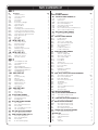
PARTS & HARDWARE LIST
BOX 1
ID
Description
!'2
!&8
!'(
!')
!'1
!("
!&9
BDK
BDJ
"$3
"$2
"$5
"$4
"$7
"$#
!6&
/UTER&LOOR0ANEL
#ENTER&LOOR0ANEL
3IDE'ABLE
3IDE'ABLE
2OOF0ANEL
2OOF0ANELFOR3KYLIGHT
#ENTER2OOF#AP
Right Shed Door
Left Shed Door
,OWER2IGHT&RONT'ABLE2OOF0ANEL
,OWER,EFT&RONT'ABLE2OOF0ANEL
5PPER2IGHT&RONT'ABLE2OOF0ANEL
5PPER,EFT&RONT'ABLE2OOF0ANEL
%NTRY'ABLE2OOF#AP
%NTRY'ABLE
v3HELF
ID
Qty
1
1
4RUSS'UTTER#HANNEL
$OOR%ND#HANNEL
Entry Header Bar
2OOF4RUSS"RACE
Wall/Shelf Support Channel
$OOR(INGE4UBE
!'0
!)1
!$7
!%%
ADZ
!(3
!#"
ADV
#ENTER4RUSS#HANNEL
Right Truss Channel
Left Truss Channel
#ORNER7ALL0ANEL
#ORNER7ALL0ANEL
Wall Panel
Window Wall Panel
Right Half-Window Wall Panel
Left Half-Window Wall Panel
(ALF7ALL7INDOW
Skylight
Roof Support Strip
Window
$OMED3KYLIGHT
,EFT%ND2OOF#AP
Right End Roof Cap
4RUSS#ONNECTOR
#ORNER3HELF
AHZ
!(-
!"5
!$7
!%%
!$*
AIA
AIB
1
6
7OOD3HIM
Wood Block
Pegboard Strip
AIK
!"6
!$"
!!"
!(9
AHW
AIO
!$7
!(8
AHV
AIL
!%"
!%%
1
1
6
1
1
1
Xv0AN(EAD3CREW
$OOR(INGE"USHING
0HILLIPS"IT
ADZ
!%$
!1:
!$8
ARA
!88
!(0
!19
ADJ
!*!
1
1
1/4” Cap Nut
Xv0AN(EAD3CREW
#AP.UT
vXv0HILLIPS4RUSS3CREW
v4HREADED2OD
1/4” x 5/8” Pan-Head Screw
ADZ
!)9
Xv#ARRIAGE"OLT
Xv&LAT7ASHER
#AP.UT
vXv"UTYL4APE
Right Door Handle
vXv#ARRIAGE"OLT
vXv3TEEL3PACER
v#ENTERLOCK.UT
,ATCH3PRING
Latch Block
Thumb Lever
Xv0AN(EAD3CREW
,ATCH#OVER0LATE
Door Latch
Right Door Lock Bracket
v&LAT7ASHER
Xv&LAT7ASHER
1
1
1
1
1
1/4” x 5/8” Pan-Head Screw
Xv&ENDER7ASHER
%NTRY'ABLE"RACKET
Xv0AN(EAD3CREW
1/8” Drill Bit
4RUSS(OLE)NSERT
#OTTER0IN
vXv0HILLIPS4RUSS3CREW
1/4” Cap Nut
v&OAM#UBE
160
1
4
1/4” x 5/8” Pan-Head Screw
3HELF3UPPORT"RACKET
14
BHI CORNER SHELF INSTALLATION HARDWARE (x2)
ADZ
1/4” x 5/8” Pan-Head Screw
4
BEI WINDOW INSTALLATION HARDWARE
18
!$7
ADZ
!)3
!$9
Xv0AN(EAD3CREW
1/4” x 5/8” Pan-Head Screw
7INDOW,ATCH"RACKET
Xv0AN(EAD3CREW
4
BHC PEGBOARD STRIP INSTALLATION HARDWARE
ADW
85
Xv0AN(EAD3CREW
BHD HOOKS BAG
BEC DOMED SKYLIGHT ASSEMBLY PARTS (x2)
!#2
!%%
!$+
!()
1
1
1
BHH 90” SHELF INSTALLATION HARDWARE (x2)
BEB WALL PANEL INSTALLATION HARDWARE
ADZ
Left Door Handle
$EADBOLT,ATCH
vXv#ARRIAGE"OLT
Xv0AN(EAD3CREW
Xv&LAT7ASHER
v#AP.UT
Left Door Lock Bracket
Left Door Strike Plate
SHELF INSTALLATION HARDWARE
BEA TRUSS FRAME ASSEMBLY HARDWARE
ADJ
!$9
!$+
!19
!$(
BEH GABLE, TRUSS, DOOR & ROOF INSTALLATION HARDWARE
4
8
1
1
BQH FLOOR ASSEMBLY HARDWARE
"1#
!(/
!$#
4
BEG RIGHT DOOR ASSEMBLY HARDWARE
BUH SMALL PARTS BOX
!)8
AIW
AFU
4
6
BEF LEFT DOOR ASSEMBLY HARDWARE
CQM SMALL PARTS KIT
AHC
AFL
AHE
!'"
!''
AFW
!18
!&:
,OUVERED6ENT
6ENT3CREEN
Xv0AN(EAD3CREW
Xv&LAT7ASHER
1/4” x 5/8” Pan-Head Screw
%ND0LUG.OTUSED
Xv0AN(EAD3CREW.OTUSED
1/4” x 1 1/8” Pan-Head Screw
ADV
1/4” x 1 1/8” Pan Head Screw
!(3 %ND0LUG
BOX 2
!'7
!',
AHD
AHH
BDI
BDH
"$6
BEE ENTRY GABLE ASSEMBLY HARDWARE
CKQ METAL PARTS KIT 2
"$1
BDP
BDO
Qty
BHV SIDE GABLE ASSEMBLY HARDWARE (x2)
CKP METAL PARTS KIT 1
!&(
!&#
BDD
!&'
AFM
#2%
Description
GABLE ASSEMBLY HARDWARE
AIF
!)'
AIH
AII
AIJ
8
v$OUBLE!RM(OOK
4” Double-Arm Hook
*(OOK
,(OOK
4OOLHOLDER
1
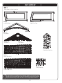
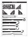
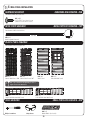
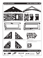
PARTS IDENTIFIER
BOX 1
Parts shown at 4% of actual size
BDJ (x1)
Left Shed Door
BDK (x1)
Right Shed Door
Rear View
BDC (x1)
%NTRY'ABLE
AGHX
3IDE'ABLE
Rear View
AGIX
3IDE'ABLE
Rear View
BDW (x1)
%NTRY'ABLE2OOF#AP
AGRX
Outer Floor Panel
AFYX
Center Roof Cap
AFXX
Center Floor Panel
!
Note: Throughout the Parts & Hardware List, Part & Hardware Identifiers, and instructions are threeletter IDs. These IDs are below the images of the parts and hardware to help you locate and identify
the parts and hardware during assembly. These IDs are not necessarily on the parts themselves.
9
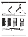
PARTS IDENTIFIER
BOX 1
Parts shown at 4% of actual size
AGQ (x4)
Roof Panel
AHBX
Roof Panel for Skylight
BDU (x1)
5PPER2IGHT&RONT'ABLE2OOF0ANEL
BDT (x1)
5PPER,EFT&RONT'ABLE2OOF0ANEL
BDR (x1)
,OWER,EFT&RONT'ABLE2OOF0ANEL
AVFX
90” Shelf
[CKP] METAL PARTS KIT 1
Parts shown at 8% of actual size
75 1/2”
*AFCX
Door End Channel
51”
*AFHX
4RUSS'UTTER#HANNEL
46”
*BDD (x1)
%NTRY'ABLE(EADER"AR
48”
*AFGX
Roof Truss Brace
67 3/4”
*AFM (x6)
Wall/Shelf Support Channel
CREX
Door Hinge Tube
74 1/2”
10
BDS (x1)
,OWER2IGHT&RONT'ABLE2OOF0ANEL
PARTS IDENTIFIER
BOX 1
[CKQ] METAL PARTS KIT 2
Parts shown at 8% of actual size
BDP (x1)
Right Truss Channel
BDO (x1)
Left Truss Channel
BDQ (x1)
Center Truss Channel
BOX 2
Parts are shown 4% of actual size
107
106
AGWX
Corner Wall Panel 106
AGLX
Corner Wall Panel 107
BDI (x1)
Right Half-Window Wall Panel
AHD (x6)
Wall Panel
BDH (x1)
Left Half-Window Wall Panel
11
AHH (x1)
Window Wall Panel
BDVX
Half-Wall Window
PARTS & HARDWARE IDENTIFIER
BOX 2
[CQM] SMALL PARTS KIT
Parts shown at 4% of actual size
116
115
AGG (x1)
Left End Roof Cap
Part shown at 8% of actual size
AFW (x1)
Right End Roof Cap
AFZX
Corner Shelf
AHC (x4)
Skylight
AGBX
Domed Skylight
[BUH] SMALL PARTS BOX
Parts are not shown to scale
AQXX
Truss Connector
AIW (x1)
Wood Block
AFL (x8)
Roof Support Strip
AIX (x4)
Wood Shim
AHE (x1)
Window
AFU (x1)
Pegboard Strip
[BEC] DOMED SKYLIGHT ASSEMBLY HARDWARE (x2)
Hardware shown at actual size (*Unless otherwise noted)
ACRX
Xv#ARRIAGE"OLT
AEEX
Xv&LAT7ASHER
ADKX
#AP.UT
*AHI (x1)
Butyl Tape
[BEA] TRUSS FRAME ASSEMBLY HARDWARE
Hardware shown at actual size (*Unless otherwise noted)
ADJ (x18)
1/4” Cap Nut
ADKX
#AP.UT
ADYX
&LAT(EAD3CREW
AQY X
vXv0HILLIPS4RUSS3CREW
13 “
*ADHXv4HREADED2OD
[CRC] FLOOR ASSEMBLY HARDWARE
Hardware shown at actual size
BQCX
Xv0AN(EAD3CREW/NLYUSED
ADC (x1)
0HILLIPS"IT
12
AHOX
Door Hinge Bushing
PARTS & HARDWARE IDENTIFIER
BOX 2
[BEB] WALL PANEL INSTALLATION HARDWARE
Hardware shown at actual size
ADZ (x85)
1/4” x 5/8” Pan-Head Screw
[BHV] SIDE GABLE ASSEMBLY HARDWARE (x2)
AEE (x5)
Xv&LAT7ASHER
Hardware shown at actual size (*Unless otherwise noted)
ADW (x5)
Xv0AN(EAD3CREW
AHSX
End Plug
ADZ (x4)
1/4” x 5/8” Pan-Head Screw
*AGP (x1)
Louvered Vent
*AIQ (x1)
Vent Screen
ADV (x6)
1/4” x 1 1/8” Pan-Head Screw
ACB (x1)
Xv0AN(EAD3CREW
[BEE] ENTRY GABLE ASSEMBLY HARDWARE
Hardware shown at actual size (*Unless otherwise noted)
ADV (x4)
1/4” x 1 1/8” Pan-Head Screw
AHSX
End Plug
[BHC] PEGBOARD STRIP INSTALLATION HARDWARE
Hardware shown at actual size
[BHD] Hooks Bag
Hardware shown at 50% of actual size
ADW (x10)
Xv0AN(EAD3CREW
(Not all screws are used)
AIJX
Toolholder
AIG (x1)
4” Double-Arm Hook
AIF (x1)
v$OUBLE!RM(OOK
AIHX
J-Hook
13
AIIX
L-Hook
PARTS & HARDWARE IDENTIFIER
BOX 2
[BEF] LEFT DOOR ASSEMBLY HARDWARE
Hardware shown at actual size (*Unless otherwise noted)
AEEX
Xv&LAT7ASHER
*AHMX
Deadbolt Latch
ABUX
vXv#ARRIAGE"OLT
ADWX
Xv0AN(EAD3CREW
*AHZ (x1)
Left Door Handle
ADJX
1/4” Cap Nut
*AIA (x1)
Left Door Lock Bracket
*AIB (x1)
Left Door Strike Plate
[BEG] RIGHT DOOR ASSEMBLY HARDWARE
Hardware shown at actual size (*Unless otherwise noted)
AEE (x5)
Xv&LAT7ASHER
ADBX
vXv3TEEL3PACER
ABVX
vXv#ARRIAGE"OLT
*AIK (x1)
Right Door Handle
AABX
1/4” Centerlock Nut
AHY (x1)
Latch Spring
*AHW (x1)
Latch Block
*AIO (x1)
Thumb Lever
ADW (x4)
Xv0AN(EAD3CREW
AEBX
1/4” Flat Washer
*AHX (x1)
Latch Cover Plate
*AHV (x1)
Door Latch
*AIL (x1)
Right Door Lock Bracket
SHELF INSTALLATION HARDWARE
Hardware shown at actual size (*Unless otherwise noted)
[BHH] 90” Shelf Installation Hardware (x2)
ADZ (x14)
1/4” x 5/8” Pan-Head Screw
[BHI] Corner Shelf Installation Hardware (x2)
*AIYX
10” Shelf Bracket
ADZ (x4)
1/4” x 5/8” Pan-Head Screw
14
PARTS & HARDWARE IDENTIFIER
BOX 2
[BEH] GABLE, TRUSS, DOOR, & ROOF INSTALLATION HARDWARE
Hardware shown at actual size (*Unless otherwise noted)
ADZ (x160)
1/4” x 5/8” Pan-Head Screw
*AXX (x4)
Truss Hole Insert
AEDX
Xv&ENDER7ASHER
AHPX
Cotter Pin
ADXX
Xv0AN(EAD3CREW
ARA (x1)
1/8” Drill Bit
AJAX
Foam Cube
AQY (x4)
vXv0HILLIPS4RUSS3CREW
*AQZX
%NTRY'ABLE"RACKET
ADJ (x4)
1/4” Cap Nut
WINDOW INSTALLATION HARDWARE
Hardware shown at actual size (*Unless otherwise noted)
[BEI] Window Installation Hardware
ADWX
Xv0AN(EAD3CREW
ADZ (x4)
1/4” x 5/8” Pan-Head Screw
ADY (x1)
Xv0AN(EAD3CREW
15
*AISX
Window Latch Bracket
SEC
TOOLS AND HARDWARE REQUIRED FOR THIS PAGE
1
Concrete (1 cu. yd.)
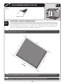
SEC
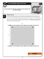
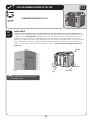
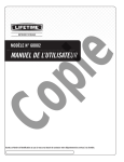
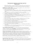
SITE PREPARATION - CONCRETE PLATFORM PREPARATION
1.1
The actual dimensions of your shed (at its widest and longest points) are 8’ x 10’. Ensure you select a site that
will accommodate these measurements. The base of the shed is slightly smaller than this, so you will need to
CREATEALEVELSURFACETHATISATLEASTvXv7ERECOMMENDUSINGALEVELCEMENTORPATIOSTYLE
surface. This will provide the best long-term performance for your shed.
!
Note: Shed Extension Kits are available for this shed. Please consider possible shed expansion when planning the site for your shed. See back cover of
this manual for information on ordering accessories.
1/4
8’
118
93
1/2
”
8’
10’
”
Fro 10’
nt
End
!
Note: Surface must be leveled before installation. If the surface is not properly leveled, the Outdoor Shed will not assemble or function correctly.
Proper surface leveling will save you time in the long run, so please do not ignore this step.
!
Note: Any platform or similar structure should be built above ground in order to avoid water pooling inside the Shed.
16
SEC
TOOLS AND HARDWARE REQUIRED FOR THIS PAGE
1
2” x 4” x 90 1/2” (x9) (Not included)
2” x 4” x 118 1/4”X.OTINCLUDED
16d 3” Common NailX.OTINCLUDED
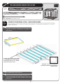
SEC
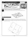
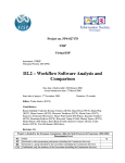
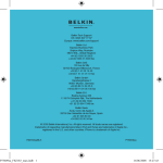
ALTERNATIVE SITE PREPARATION: OPTION 1 - WOOD PLATFORM ASSEMBLY
1.2
%NSUREALLLUMBERUSEDISTREATEDANDAPPROVEDFOROUTDOORUSE"UILDOUTSIDEFRAMETOvXv
outside dimensions:
Note: Whenever possible, you should use the surfaces described on Page
7. When this is not possible, we recommend you use a wood platform or a
filled wood frame.
!
118 1/4”
93
1/2
16”
”
16”
16”
16”
16”
16”
16”
To ensure studs are in the correct location
for nailing plywood in the next step, start
measuring from the corner 16”, and then
measure from center to center.
t
Fron
!
Note: All lumber must be rated for outdoor use.
!
Note: Surface must be leveled before installation. If the surface is not
properly leveled, the Outdoor Shed will not assemble or function correctly.
Proper surface leveling will save you time in the long run, so please do not
ignore this step.
17
End
Place the 2” x 4” x 90 1/2” boards on the
inside of the frame. Nail each board in place
with the 16d nails.
SEC
TOOLS AND HARDWARE REQUIRED FOR THIS PAGE
1
22 1/4” x 93 1/2” x 3/4” Treated Plywood (x1)
(Not included)
8d 1 1/2” Common Nail X
(Not included)
48” x 93 1/2” x 3/4” Treated PlywoodX
(Not included)
SEC
1.3
ALTERNATIVE SITE PREPARATION: OPTION 1 - WOOD PLATFORM ASSEMBLY (CONT)
Square up the frame by measuring from corner to corner. Measurement A should equal Measurement B.
B
A
!
Note: All lumber must be rated for outdoor use.
SEC
Cut Plywood into sizes called for on previous page. Arrange the Plywood according to the diagram and nail into
PLACEWITHDXvNAILS0LACEPLATFORMINTHEDESIREDLOCATION)FPLATFORMDOESNOTRESTLEVELONTHEGROUND
BUILDUPLOWPOINTSWITHLOOSEDIRTUNTILPLATFORMISSTABLE$RILLTHREEEVENLYSPACEDvDRAINHOLESINPLYWOOD
BETWEENEACHvXvJOIST
x9
31
/2”
x9
31
/2”
93
1/2
”
48”
1/4
”x
48”
Fro
nt E
nd
22
1.4
18
SEC
TOOLS AND HARDWARE REQUIRED FOR THIS PAGE
1
2” x 4” x 120”X.OTINCLUDED
2” x 6” x 89”X.OTINCLUDED
Pea Gravel (9.8 Cubic Feet) L-Bracket (x4)
(Not included)
(Not included)
8d 1 1/2” Common Nail (x16)
(Not included)
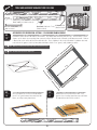
ALTERNATIVE SITE PREPARATION: OPTION 2 - FILLED WOOD FRAME ASSEMBLY
SEC
1.5
Cut outside frame to 8’ x 10’ outside dimensions. Lay boards flat so widest parts face up. Ensure frame is level.
Square up the frame by measuring from corner to corner. Measurement A should equal Measurement B. Nail an
L-Bracket on each corner of the frame with 8d nails. Place platform in the desired location. If platform does not
RESTLEVELONTHEGROUNDBUILDUPLOWPOINTSWITHLOOSEDIRTORh0EAvGRAVELUNTILPLATFORMISSTABLE
!
Note: Whenever possible you should use the surfaces described on Page 7.
!
Note: All lumber must be rated for outdoor use.
0”
12
B
”
x6
2” ards
Bo
A
nd
”
89
E
nt
”
96
SEC
1.6
Fro
SEC
Once all boards are level and do not wobble,
PACKh0EAvGRAVELAROUNDTHEOUTSIDEOFTHE
frame, and slope away from frame.
1.7
2” x 4” x 8’ Leveling Board (x1)
19
.OWlLLTHEINSIDEOFTHEFRAMEWITHh0EAv
gravel. Use a leveling board to scrape off extra
fill material and to level the surface.
SEC
2
FLOOR ASSEMBLY
HARDWARE REQUIRED
HARDWARE BAG REQUIRED: BQH
Part shown at actual size
BQCX
Xv0AN(EAD3CREW
/NLYUSED
ADC (x1)
0HILLIPS"IT
AHOX
Door Hinge Bushing
PLASTIC PARTS REQUIRED
Parts shown at 4% of actual size
AGRX
Outer Floor Panel
AFXX
Center Floor Panel
TOOLS REQUIRED
Phillips Screwdriver
HARDWARE BAG REQUIRED: BQH
ADC (x1)
0HILLIPS"IT)NCLUDED
Safety Glasses
20
SEC
TOOLS AND HARDWARE REQUIRED FOR THIS PAGE
2
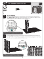
NO HARDWARE REQUIRED FOR THIS STEP
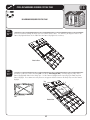
SEC
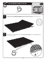
FLOOR ASSEMBLY
2.1
Lay an Outer Floor Panel (AGR) flat on the ground. Hold a Center Floor Panel (AFX) at an angle as shown and fit tabs
into slots. Lay Center Floor Panel flat.
AFX
AGR
!
Note: Ensure you insert the Inner Floor Panel (AFX) with the Door Hinge
Bushing Holes toward the outside. You’ll place the Doors here later.
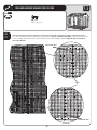
SEC
2.2
Hold the second Center Floor Panel (AFX) at an angle as shown and fit tabs into slots. Lay Center Floor Panel flat.
AFX
!
Note: Ensure you insert the Inner Floor Panel (AFX) with the Door Hinge
Bushing Holes toward the outside. You’ll place the Doors here later.
CAUTION
Sharp objects may damage your floor. If resting
sharp, heavy objects on your shed floor, place a
block of wood between the sharp object and floor.
21
SEC
TOOLS AND HARDWARE REQUIRED FOR THIS PAGE
AHOX
SEC
2.3
Finally, connect the last Outer Floor Panel (AGR) to the Center Floor Panel and lay flat.
AGR
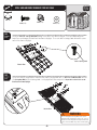
SEC
2.4
,IFTTHE&LOOR0ANELSUPENOUGHTOSLIDETHETWODoor Hinge Bushings (AHO) under and up through the holes in
the Floor Panels as shown.
AHO
AHO
22
2
SEC
TOOLS AND HARDWARE REQUIRED FOR THIS PAGE
2
BQCX
/NLYUSED
SEC
2.5
&ACETHESEAMOFTWOADJACENT&LOOR0ANELS)NSERTTWO#8 x 1/2” Pan-Head Screws (BQC) near the seam of a Floor
Panel and down into the tab of the adjacent Floor Panel at the locations shown. Repeat this step for both sides of
each seam in the Floor.
Insert Screws here.
Seam
Insert Screws here.
23
SEC
TOOLS AND HARDWARE REQUIRED FOR THIS PAGE
2
IF YOU PLAN ON ANCHORING YOUR SHED, CHECK WITH YOUR LOCAL HARDWARE STORE
FOR SUITABLE HARDWARE.
SEC
2.6
ANCHORING THE SHED
If you plan on anchoring your shed, you can anchor it to your platform through the four indentations near the
corners of the floor. The anchoring hardware used depends on the platform. If you have a concrete platform,
WERECOMMENDUSINGFOURv!NCHOR"OLTSANDFOURvXv&LAT7ASHERS)FYOUHAVEAWOODFRAMED
PLATFORMWERECOMMENDUSINGFOURv,AG"OLTSANDFOURvXv&LAT7ASHERS$ONOTEXCEEDA
vDIAMETERBOLT2EFERTOYOURLOCALHARDWARESTOREFORTHISHARDWAREDo not tighten the anchoring hardware until
instructed to do so at the end of these instructions.
10’
8’
WARNING
Failure to anchor the shed may result in property
damage and/or personal injury.
24
SEC
3
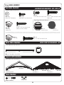
TRUSS ASSEMBLY
HARDWARE REQUIRED
HARDWARE BAG REQUIRED: BEA
Hardware shown at actual size (*Unless indicated otherwise)
ADJ (x18)
1/4” Cap Nut
AQY X
vXv4RUSS3CREW
ADYX
Xv3CREW
ADKX
#AP.UT
13 “
*ADHXv4HREADED2OD
PARTS & METAL KITS REQUIRED: CKP, CKQ, CQM
METAL PARTS REQUIRED
Parts shown at 8% of actual size (*Unless indicated otherwise)
BDP (x1)
Right Angled Truss Channel
BDQ (x1)
Center Truss Channel
BDO (x1)
Left Angled Truss Channel
AQXX
Truss Connector
51”
AFHX
4RUSS'UTTER#HANNEL
48”
AFGX
Roof Truss Brace (Not to Scale)
TOOLS REQUIRED
Phillips Screwdriver
3/8” Wrench
7/16” WrenchX
25
Safety Glasses
SEC
TOOLS AND HARDWARE REQUIRED FOR THIS PAGE
7/16”
ADJ (x4)
AQY (x4)
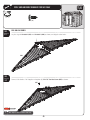
SEC
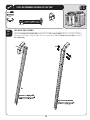
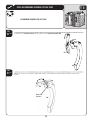
SIDE ANGLED TRUSS ASSEMBLY
3.1
Stand the Left Angled Truss Channel (BDO) upright and set a Truss Connector (AQX) inside the end of the Left Angled
4RUSS#HANNELASSHOWN!LIGNTHEHOLESANDSECUREWITHTWO1/4” x 2” Phillips Truss Screws (AQY)ANDTWO
1/4” Cap Nuts (ADJ).
AQX
ADJ
AQY
BDO
26
3
SEC
TOOLS AND HARDWARE REQUIRED FOR THIS PAGE
3
7/16”
ADJ (x4)
AQY (x4)
SEC
3.2
Connect a Truss Gutter Channel (AFH)TOTHE4RUSS#ONNECTORUSINGTWO1/4” x 2” Phillips Truss Screws (AQY) and two
1/4” Cap Nuts (ADJ).
AQX
AFH
BDO
AQY
AQX
ADJ
27
SEC
TOOLS AND HARDWARE REQUIRED FOR THIS PAGE
3
3/8”
ADY (x8)
ADK (x8)
SEC
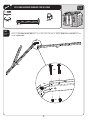
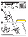
3.3
With the Angled Truss Assembly on its side, align the holes in a Roof Truss Brace (AFG) with those circled in the Left
!NGLED4RUSS#HANNELAND4RUSS'UTTER#HANNELASSHOWN
AFG
SEC
3.4
3ECURETHE2OOF4RUSS"RACETOTHE,EFT!NGLED4RUSS#HANNELUSINGTWO#10 x 3/8” Pan-Head Screws (ADY) and
TWO#10 Cap Nuts (ADK). Repeat this step for the other end of the Roof Truss Brace.
ADK
ADY
ADK
WARNING
!
Do not overtighten the Cap Nut. If the end of
the Bolt breaks through the plastic cap, call our
Customer Service Department. Exposed threads
on the end of the Bolt may cause serious injuries.
Note: The Cap Nuts goes on the outside of the Truss.
28
SEC
TOOLS AND HARDWARE REQUIRED FOR THIS PAGE
7/16”X
3
ADJ (x4)
13 “
ADHX.OTTOSCALE
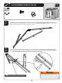
SEC
3.5
With the Angled Truss Assembly on its side, slide a 1/4” Threaded Rod (ADH) through the Roof Truss Brace and the
Truss Connector as shown. Secure the top and bottom of the 1/4” Threaded Rod with a 1/4” Cap Nut (ADJ). Tighten
all hardware. The 1/4” Threaded Rod will still spin freely. Set aside. Repeat previous steps for the Right Angled Truss
Assembly.
ADH
ADJ
ADJ
WARNING
Do not overtighten the Cap Nut.
29
SEC
TOOLS AND HARDWARE REQUIRED FOR THIS PAGE
ADJ (x4)
7/16”
AQY (x4)
SEC
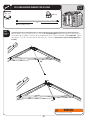
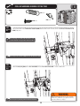
CENTER ANGLED TRUSS ASSEMBLY
3.6
Attach a Truss Connector (AQX) to the Center Angled Truss Channel (BDQ) using the hardware shown.
AQX
AQX
ADJ
AQY
BDQ
WARNING
Do not overtighten the Cap Nut.
SEC
3.7
Attach a Truss Gutter Channel (AFH) to the Truss Connector using the hardware shown.
AFH
ADJ
AQY
30
3
SEC
TOOLS AND HARDWARE REQUIRED FOR THIS PAGE
3
3/8”
ADY (x4)
ADK (x4)
SEC
!LIGNTHEHOLEINTHE2OOF4RUSS"RACEWITHTHATCIRCLEDONTHE4RUSS'UTTER#HANNELINTHEIMAGEBELOW!TTACHA
Roof Truss Brace (AFG) to the Center Truss Assembly using the hardware shown.
3.8
AFG
ADK
ADY
ADK
ADK
ADY
ADK
Bracket
!
Note: The Roof Truss Brace goes inside the bracket.
WARNING
Do not overtighten the Cap Nut.
31
SEC
TOOLS AND HARDWARE REQUIRED FOR THIS PAGE
ADJX
7/16”X
13 “
ADH (x1) (Not to scale)
SEC
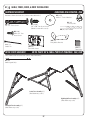
3.9
Insert a 1/4” Threaded Rod (ADH) through the Roof Truss Brace and Truss Connector as shown. Ensure channels
are parallel, then secure with 1/4” Cap Nuts (ADJ). Tighten all hardware. The 1/4” Threaded Rod will still spin
freely. Set aside.
ADH
ADJ
ADJ
WARNING
Do not overtighten the Cap Nut.
32
3
SEC
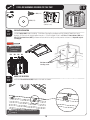
4 WALL PANEL INSTALLATION
HARDWARE BAG REQUIRED: BEB
HARDWARE REQUIRED
Hardware shown at actual size
ADZ (x85)
1/4” x 5/8” Pan-Head Screw
(Not all screws will be used)
METAL PARTS KIT REQUIRED: CKP
METAL PARTS REQUIRED
Part shown at 8% of actual size
67 3/4”
AFMX
Wall Support Channel
PLASTIC PARTS REQUIRED
Part shown at 4% of actual size
106
107
AGLX
AGWX
Corner Wall Panel 106 Corner Wall Panel 107
!
AHD (x6)
Wall Panel
AHH (x1)
Window Wall Panel
Note: Pay no attention to the imprinting of “Left” or
“Right” on the Corner Wall Panels.
BDH (x1)
Left Half-Window Wall Panel
BDI (x1)
Right Half-Window Wall Panel
SMALL PARTS BOX REQUIRED: BUH
TOOLS REQUIRED
Phillips Screwdriver
Safety Glasses
AIW (x1)
Wood Block (Included)
33
SEC
TOOLS AND HARDWARE REQUIRED FOR THIS PAGE
4
ADZX
AIW (x1)
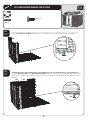
SEC
WALL PANEL INSTALLATION
4.1
Fold a Corner Wall Panel 107 (AGL). Fit tabs of Panel into the front, left corner of your Floor (while facing shed).
Place a Wood Block (AIW) under floor panel, directly under the first tab, then pull down on the Corner Panel until
the tab snaps into place. Move the Wood Block under the next tab and repeat.
AGL
AIW
!
Note: Place the Wood Block (AIW) directly under the tabs as you insert
them throughout the assembly. Snap tabs into place one at a time.
SEC
Snap Wall Panels (AHD) into place along the side of the shed. Ensure the tops of the Wall Panels are even and the
holes align. Use one (1) 1/4” x 5/8” Pan-Head Screw (ADZ)TOFASTENTHETOPOFTHE0ANELSTOGETHERASSHOWN9OULL
finish fastening the panels together towards the end of this section.
4.2
AHD
AHD
AIW
ADZ
!
Note: A second person should apply pressure on opposite side of the Wall
Panels for easier insertion of the Screw. Do not overtighten Screw.
34
SEC
TOOLS AND HARDWARE REQUIRED FOR THIS PAGE
4
ADZ (x4)
AIW (x1)
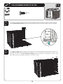
SEC
4.3
Fold a Corner Wall Panel 106 (AGW). Snap into place and fasten at the top hole with the required hardware.
AGW
AIW
SEC
4.4
Insert two Wall Panels (AHD) and a Window Wall Panel (AHH) along back side of shed. The Window Wall Panel may be
placed in any rear Wall Panel position. Ensure holes line up and fasten Panels at the top hole with the required
hardware.
AHH
AHD
AHD
AIW
35
SEC
TOOLS AND HARDWARE REQUIRED FOR THIS PAGE
4
ADZX
AIW (x1)
SEC
4.5
Fold a Corner Wall Panel 107 (AGL) and fasten to the rear Wall Panel in the top hole using the required hardware.
AGL
AIW
SEC
4.6
Snap Wall Panels (AHD) into place along the side of the shed. Ensure the tops of the Wall Panels are even and the
holes align. Use one (1) 1/4” x 5/8” Pan-Head Screw (ADZ)TOFASTENTHETOPOFTHE0ANELSTOGETHERASSHOWN9OULL
finish fastening the panels together towards the end of this section.
AHD
36
AHD
SEC
TOOLS AND HARDWARE REQUIRED FOR THIS PAGE
4
ADZ (x51)
AIW (x1)
SEC
4.7
Fold the second Corner Wall Panel 106 (AGW) and snap it into place at the right, front corner of the Floor as shown.
Fasten it to the Wall Panel in the top hole using the required hardware.
AGW
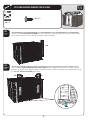
SEC
4.8
Snap the Left and Right Half-Window Wall Panels (BDI & BDH) into place along the front of the Shed. After ensuring
holes line up, fasten Panels together with the required hardware. Finish fastening all Panels together with rest of
the 1/4” x 5/8” Pan-Head Screws (ADZ) for all holes.
BDH
BDI
AIW
37
SEC
TOOLS AND HARDWARE REQUIRED FOR THIS PAGE
ADZ (x4)
SEC
4.9
Attach a Wall Support Channel (AFM) to the Right Half-Window Wall Panel, and secure with four (4) 1/4” x 5/8” PanHead Screws (ADZ).
Use 2nd groove from the right
Use 2nd groove from the right
AFM
ADZ
AFM
ADZ
ADZ
ADZ
!
Note: Use second groove in from edge
for Right Half-Window Wall Panel (BDH).
38
4
SEC
TOOLS AND HARDWARE REQUIRED FOR THIS PAGE
ADZ (x4)
SEC
Attach a Wall Support Channel (AFM) to the Left Half-Window Wall Panel (use the first groove in from the edge, and
secure with four (4) 1/4” x 5/8” Pan-Head Screws (ADZ).
4.10
Use 1st groove from the left
Use 1st groove from the left
AFM
ADZ
AFM
ADZ
ADZ
ADZ
!
Note: Use first groove in from edge for
Left Half-Window Wall Panel (BDI).
39
4
SEC
5
DOMED SKYLIGHT ASSEMBLY
HARDWARE REQUIRED
HARDWARE BAG REQUIRED: BEC (x2)
Hardware is actual size (*Unless indicated otherwise)
ACRX
Xv#ARRIAGE"OLT
AEEX
Xv&LAT7ASHER
ADKX
#AP.UT
SMALL PARTS KIT REQUIRED: CQM
PLASTIC PARTS REQUIRED
Part shown at 4% actual size
AHBX
Roof Panel for Domed Skylight
*AHIX"UTYL4APE
Part shown at 8% actual size
AGBX
Domed Skylight
TOOLS REQUIRED
Plain Screwdriver
3/8” Wrench
Safety Glasses
40
SEC
TOOLS AND HARDWARE REQUIRED FOR THIS PAGE
5
AHIX
(Not to scale)
SEC
5.1
DOMED SKYLIGHT ASSEMBLY
Use a plain screwdriver to gently remove any excess plastic from the twelve holes in the Roof Panel for Domed
Skylight (AHB). It’s important that the hole stay square; try not to round the corners of the edges of the holes.
AHB
!
Note: Use a plain screwdriver to remove any excess plastic from
all holes in Panel. Ensure the holes remain square.
SEC
5.2
Stick the end of the Butyl Tape (AHI) over the groove and top, left hole of the Roof Panel for Domed Skylight as
indicated below. Move to the right and over the groove covering all the holes along the top of the opening. Once
the top, right corner and hole are covered, cut the Butyl Tape. Run your finger along the paper backing pressing
down slightly to remove any gaps or bubbles between the Butyl Tape and the groove. Remove the paper backing
from the piece you just applied. Overlap the end of the roll of Butyl Tape with the end you just cut and apply the
Butyl Tape over the holes along the groove on the right of the opening. Continue applying the Butyl Tape in this
fashion until all holes have been covered and the ends overlap.
Start applying Butyl Tape here over
the holes along the groove and move
clockwise around the opening. Ensure
all holes are completely covered.
!
Note: Butyl Tape must overlap at ends and cover all twelve holes.
41
SEC
TOOLS AND HARDWARE REQUIRED FOR THIS PAGE
NO HARDWARE REQUIRED FOR THIS PAGE
SEC
5.3
Insert a screwdriver through the Butyl Tape and into the twelve holes. This will help you align the holes in the
Domed Skylight with those in the Roof Panel for Domed Skylight in the next step.
Exterior View
SEC
5.4
Remove the protective plastic film from both sides of the Domed Skylight (AGB). Carefully align the holes in the
Domed Skylight with those in the Butyl Tape. Set the Domed Skylight over the opening in the Roof Panel for
Domed Skylight. Press down and verify there are no gaps or bubbles between the Butyl Tape and the Domed
Skylight.
Top
AGB
AGB
Exterior View
42
5
SEC
TOOLS AND HARDWARE REQUIRED FOR THIS PAGE
5
3/8”
ADKX
AEEX
ACRX
SEC
5.5
Insert one #10 x 5/8” Carriage Bolt (ACR) through each hole in the Domed Skylight. Press the Bolt through the
Butyl Tape and through the Roof Panel for Domed Skylight. The necks of the Carriage Bolts fit into the square
holes in the Domed Skylight.
Top
Neck of Carriage Bolt
Exterior View
SEC
5.6
Secure the Domed Skylight to the Roof Panel for Domed Skylight with one (1) #10 x 1/2” Flat Washer (AEE) and one
(1) #10 Cap Nut (ADK) for each Carriage Bolt. Set Skylight/Panel Assembly aside. Repeat this section for the second
Roof Panel for Domed Skylight.
ADK
ADK
AEE
AEE
ADK
ADK
AEE
ADK
AEE
AEE
Interior View
WARNING
Do not overtighten the Cap Nut. If the end of
the Bolt breaks through the plastic cap, call our
Customer Service Department. Exposed threads
on the end of the Bolt may cause serious injuries.
43
SEC
6 GABLE ASSEMBLY
HARDWARE REQUIRED
HARDWARE BAG REQUIRED: BEE, BHV (x2)
Hardware shown at actual size
ADVX
ADZ (x8)
1/4” x 5/8” Pan-Head Screw 1/4” x 1 1/8” Pan-Head Screw
(Not used)
ADW (x10)
Xv0AN(EAD3CREW
AEE (x10)
Xv&LAT7ASHER
Parts shown at 8% of actual size
ACBX
Xv0AN(EAD3CREW
(Not used in this model)
AHS (x4)
End Plug
(Not used)
AGPX
Louvered Vent
AHSX
End Plug
AIQX
Vent Screen
ADV (x4)
1/4” x 1 1/8” Pan-Head Screw
METAL PARTS KIT REQUIRED: CKP
METAL PARTS REQUIRED
Parts shown at 8% of actual size
46”
BDDX%NTRY'ABLE(EADER"AR
PLASTIC PARTS REQUIRED
Parts shown at 4% of actual size
(Front View)
BDC (x1)
&RONT%NTRY'ABLE
AGHX
3IDE'ABLE
TOOLS REQUIRED
Phillips Screwdriver
Safety Glasses
44
(Rear View) AGIX
3IDE'ABLE
(Rear View)
SEC
TOOLS AND HARDWARE REQUIRED FOR THIS PAGE
ADZ (x8)
SEC
SIDE GABLE ASSEMBLY
6.1
Lay the edge of Side Gable 2 (AGI) over Side Gable 1 (AGH) as shown, and align the four holes.
AGI
AGH
SEC
6.2
#ONNECT3IDE'ABLES together using four (4) 1/4” x 5/8” Pan-Head Screws (ADZ) as shown.
ADZ
ADZ
!
Note: Only use a hand screwdriver in this step.
45
6
SEC
TOOLS AND HARDWARE REQUIRED FOR THIS PAGE
6
AEE (x10)
ADW (x10)
SEC
6.3
,AY3IDE'ABLE!SSEMBLYmATONTHEGROUNDOVERTHEVent Screen (AIQ) and Louvered Vent (AGP). Align the holes in the
,OUVERED6ENTWITHTHOSEINTHE3IDE'ABLE!SSEMBLY
AIQ
AGP
SEC
6.4
!FTERALIGNINGTHEHOLESPRESSDOWNlRMLYONTHE3IDE'ABLE!SSEMBLYWHENINSERTINGTHElVE#10 x 3/4” PanHead Screws (ADW) and the five (5) #10 x 1/2” Flat Washers (AEE). Pressing down firmly while inserting the Screws will
help prevent the Vent Screen from twisting while inserting the Screws. Repeat the previous steps for the second Side
Gable.
ADW
AEE
!
!
Note: Only use a hand screwdriver in this step.
46
Note: Press down firmly on the Gable to help prevent
the Screen from twisting while inserting the Screws.
SEC
TOOLS AND HARDWARE REQUIRED FOR THIS PAGE
6
ADV (x4)
AHSX
SEC
FRONT ENTRY GABLE ASSEMBLY
6.5
Insert one End Plug (AHS) into each end of the Entry Gable Header Bar (BDD) as shown, and align the four holes in the
%NTRY'ABLE(EADER"ARWITHTHOSEINTHEFront Entry Gable (BDC).
AHS
BDD
AHS
BDC
!
!
Note: The indented, oval holes face toward the Gable.
Note: The indented, square hole faces downward
and to the right of center.
SEC
6.6
!TTACHTHE%NTRY'ABLE(EADER"ARTOTHE&RONT%NTRY'ABLEUSINGFOUR1/4” x 1 1/8” Pan-Head Screws (ADV). Set
aside.
ADV
ADV
!
Note: Only use a hand screwdriver in this step.
47
SEC
7
LEFT DOOR ASSEMBLY
HARDWARE BAG REQUIRED: BEF
HARDWARE REQUIRED
Hardware shown at actual size
ADWX
Xv0AN(EAD3CREW
ABUX
vXv#ARRIAGE"OLT
0ARTSHOWNATOFACTUALSIZE
AHMX
Deadbolt Latch
ADJX
1/4" Cap Nut
AEEX
X&LAT7ASHER
Part shown at 15% of actual size
AHZ (x1)
Left Door Handle
AIB (x1)
Left Door Strike Plate
AIA (x1)
Left Door Lock Bracket
METAL PARTS REQUIRED
METAL PARTS KIT REQUIRED: CKP
Part shown at 8% of actual size
75 1/2”
AFC (x1)
Door End Channel
CREX
Door Hinge Tube
74 1/2”
PLASTIC PARTS REQUIRED
Part shown at 4% of actual size
BDJ (x1)
Left Front Door
TOOLS REQUIRED
Phillips Screwdriver
Safety Glasses
7/16” Wrench
48
SEC
TOOLS AND HARDWARE REQUIRED FOR THIS PAGE
AHMX
SEC
LEFT DOOR ASSEMBLY
7.1
Rest the Left Shed Door (BDJ) with front side down. Slide a Door Hinge Tube (CRE) through the hole in the Door as
shown.
CRE
BDJ
Back of Door
SEC
7.2
Position the Deadbolt Latches (AHM) in slots at the top and bottom of the Door, then slide the Door End Channel (AFC)
onto the Door as shown.
AFC
Back of Door
AFC
AHM
AHM
BDJ
BOTTOM
TOP
!
AFC
Note: The Door End Channel fits onto Door with the flat side up (facing the Deadbolt Latches).
49
7
SEC
TOOLS AND HARDWARE REQUIRED FOR THIS PAGE
7
7/16”
ABUX
AIB (x1)
ADJX
AIA (x1)
SEC
7.3
Slip the Left Door Strike Plate (AIB) over the Left Shed Door and align the holes.
AIB
!
Note: You may need to nudge the Door End Channel to make these holes line up with the gap in the Door.
SEC
7.4
Attach the Left Door Lock Bracket (AIA)TOTHE,EFT$OOR3TRIKE0LATEWITHTWO1/4” x 1 1/2” Carriage Bolts (ABU) and
TWO1/4” Cap Nuts (ADJ).
ADJ
WARNING
AIA
Do not overtighten the Cap Nut. If the end of
the Bolt breaks through the plastic cap, call our
Customer Service Department. Exposed threads
on the end of the Bolt may cause serious injuries.
ABU
50
SEC
TOOLS AND HARDWARE REQUIRED FOR THIS PAGE
ADWX
AEEX
SEC
7.5
Attach the Left Door Handle (AHZ) to the Door using three #10 x 1/2” Flat Washers (AEE) and three #10 x 3/4” Pan-Head
Screws (ADW).
ADW
AEE
ADW
AEE
AHZ
51
7
SEC
8
RIGHT DOOR ASSEMBLY
HARDWARE REQUIRED
HARDWARE BAG REQUIRED: BEG
Hardware shown at actual size
AEEX
X&LAT7ASHER
ABVX
X#ARRIAGE"OLT
AHY (x1)
Latch Spring
ADW (x4)
X0AN(EAD3CREW
AIL (x1)
Right Door Lock Bracket
AHV (x1)
Door Latch
AIO (x1)
Thumb Lever
AABX
1/4” Centerlock Nut
AEBX
1/4” Flat Washer
Part shown at 15% of
actual size
0ARTSHOWNATOFACTUALSIZE
AHX (x1)
Latch Cover Plate
ADBX
vXv3TEEL3PACER
AIK (x1)
Right Door Handle
Part shown at 50%
of actual size
AHW (x1)
Thumb Lever Extension
METAL PARTS KIT REQUIRED: CKP
METAL PARTS REQUIRED
Part shown at 8% of actual size
75 1/2”
AFC (x1)
Door End Channel
74 1/2”
CREX
Door Hinge Tube
PLASTIC PARTS REQUIRED
Part shown at 4% of actual size
BDK (x1)
Right Front Door
TOOLS REQUIRED
Phillips Screwdriver
7/16” Wrench
Safety Glasses
52
SEC
TOOLS AND HARDWARE REQUIRED FOR THIS PAGE
NO HARDWARE REQUIRED FOR THIS PAGE
SEC
8.1
RIGHT DOOR ASSEMBLY
Rest the Right Shed Door (BDK) with front side down. Slide a Door Hinge Tube (CRE) through the hole in the Door as
shown.
CRE
Back of Door
BDK
SEC
8.2
Slide the Door End Channel (AFC) onto the Door as shown.
AFC
AFC
Back of Door
BDK
53
8
SEC
TOOLS AND HARDWARE REQUIRED FOR THIS PAGE
NO HARDWARE REQUIRED FOR THIS PAGE
SEC
8.3
Fit knobs of the Thumb Lever (AIO) into the grooves of the Right Door Handle (AIK).
Groove
Knob
AIO
AIK
SEC
8.4
Rotate the Thumb Lever into the Right Door Handle. Slide forward until the knobs fit into the holes in the
Handle.
AIO
Knobs snap
into holes
AIK
54
8
SEC
TOOLS AND HARDWARE REQUIRED FOR THIS PAGE
ADWX
ABVX
7/16”
8
AEEX
AHX (x1)
AEBX
AABX
ADBX
AIL (x1)
AHV (x1)
SEC
8.5
!TTACHTHE2IGHT(ANDLE!SSEMBLYTOTHE$OORUSINGTHREE#10 x 1/2” Flat Washers (AEE)ANDTHREE#10 x 3/4”
Pan-Head Screws (ADW).
AIO
AIK
ADW
AEE
ADW AEE
CAUTION
Do not overtighten. Overtightening may damage
parts and void warranty.
SEC
8.6
Install Handle Latch assembly onto the Right Door using the required hardware.
AHV
ABV
AHV
ADB
AIO
AAB
AEB
AHX
!
Note: The Door Latch (AHV) goes on top of the Thumb Lever (AIO).
55
AIL
SEC
TOOLS AND HARDWARE REQUIRED FOR THIS PAGE
AHY (x1)
AHW (x1)
ADW (x1)
SEC
8.7
!
Line up the hole in the Thumb Lever Extension (AHW) with the hole in the Thumb Lever and #10 x 3/4” Pan-Head Screw
(ADW) into place.
Note: The Spring is not shown in this illustration in order
to better show the correct placement of the Latch Block.
ADW
AHW
Lip
!
Note: The lip of the Latch Block (AHW) fits under the Thumb Lever (AIO).
SEC
Attach Latch Spring (AHY) to the Door Latch (AHV) and the Latch Cover Plate (AHX). Set the Door aside.
8.8
AHV
AHY
AHX
WARNING
!
While performing this step, each person
should use protective eye glasses to help
prevent serious eye injury.
Note: Use pliers to pull spring down and hook into bottom hole.
56
8
SEC
9
GABLE, TRUSS, DOOR, & ROOF INSTALLATION
HARDWARE REQUIRED
HARDWARE BAG REQUIRED: BEH
Hardware shown at actual size (*Unless noted otherwise)
AQY (x4)
vXv4RUSS3CREW
AED X
Xv&ENDER7ASHER
ADZ (x160)
1/4” x 5/8” Pan-Head Screw
(Not all screws will be used)
ADJ (x4)
1/4” Cap Nut
ARA (x1) 1/8” Drill Bit
ADXX
Xv0AN
Head Screw
*AQZX
%NTRY'ABLE"RACKET
AHP (x4)
Cotter Pin
METAL PARTS REQUIRED
*AXX (x4)
Truss Hole Insert
*AJAX
Foam Cube
METAL PARTS KIT & SMALL PARTS KIT REQUIRED: CKQ, CQM
Parts shown at 8% of actual size (Unless noted otherwise)
AFL (x8)
Roof Support Strip
Center Truss Assembly (x1)
(Not shown any scale)
Right Angled Truss Assembly (x1)
(Not shown any scale)
Left Angled Truss Assembly (x1)
(Not shown any scale)
57
SMALL PARTS KIT REQUIRED: CQM
PLASTIC PARTS REQUIRED
Parts shown at 4% of actual size
Entry Gable Assembly (x1)
Side Gable AssemblyX
115
AGQ (x4)
Roof Panel
Roof Panel for Skylight AssemblyX
BDJ (x1)
Left Front Door Assembly (Notched)
BDT (x1)
5PPER,EFT&RONT'ABLE2OOF0ANEL
116
AFW (x1)
AGG (x1)
AFYX
Right End Roof Cap
Left
End
Roof
Cap
Center Roof Cap
BDK (x1)
Right Front Door Assembly (Notched)
BDU (x1)
5PPER2IGHT&RONT'ABLE2OOF0ANEL
BDW (x1)
%NTRY'ABLE2OOF#AP
Part shown at 8% of actual size
BDR (x1)
,OWER,EFT&RONT'ABLE2OOF0ANEL
BDS (x1)
,OWER2IGHT&RONT'ABLE2OOF0ANEL
HARDWARE BAG REQUIRED: BEH
TOOLS REQUIRED
Phillips Screwdriver
AHC (x4)
Skylight
Pliers
7/16”
ARA (x1) 1/8” Drill BIt (Included)
58
Safety Glasses
SEC
TOOLS AND HARDWARE REQUIRED FOR THIS PAGE
9
ADZ (x14)
2 ADULTS REQUIRED FOR STEPS 9.1 - 9.2
SEC
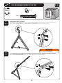
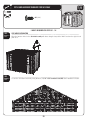
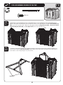
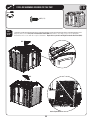
SIDE GABLE INSTALLATION
9.1
Align the fourteen holes in the Side Gable Assembly with those along the tops of the Wall Panels on the right side of
your shed.
SEC
9.2
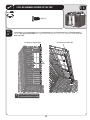
3ECURETHE3IDE'ABLE!SSEMBLYUSINGFOURTEEN1/4” x 5/8” Pan Head Screws (ADZ) at the locations indicated.
59
SEC
TOOLS AND HARDWARE REQUIRED FOR THIS PAGE
9
NO HARDWARE REQUIRED FOR THIS STEP
3 ADULTS REQUIRED FOR STEPS 9.3 - 9.23
SEC
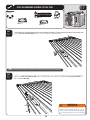
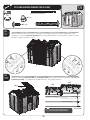
TRUSS & ROOF INSTALLATION
9.3
Place the ends of the Right Angled Truss Assembly into the first set of notches on the Wall Panels as shown. The
angled arm faces inward.
Angled Arm
!
Note: Ensure to carefully read and follow the roof installation instructions and notes. Following each
step in the order listed will minimize potential complications during installation.
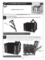
SEC
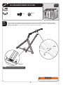
9.4
While one adult holds the Right Angled Truss Assembly in place, set a Roof Panel for Domed Skylight Assembly onto
THE2IGHT!NGLED4RUSS!SSEMBLYAND2IGHT'ABLE4HEEDGEOFTHE2OOF0ANELFOR$OMED3KYLIGHTlTSDOWN
inside the Truss Channels. Ensure the alignment nub in the Roof Panel fits into notch on the Truss (this helps to
ALIGNTHEHOLESINTHE2OOF0ANELWITHTHOSEINTHE4RUSSTHE7ALL0ANELAND'ABLE
Alignment Nub
& Notch
!
Note: The edge of the Roof Panel fits into the Truss Assembly.
Interior Upward View
60
SEC
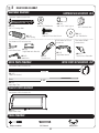
TOOLS AND HARDWARE REQUIRED FOR THIS PAGE
(Not actual size)
9
AFLX
ADZX
SEC
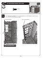
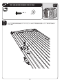
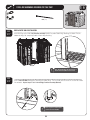
9.5
7ITHTHE2OOF0ANELFOR$OMED3KYLIGHT!SSEMBLYINPOSITIONBETWEENTHE'ABLEAND4RUSSSLIDETWORoof
Supports (AFL) into place within the notches of the Roof Panel for Domed Skylight. The bottom lip of the Roof
Panels fit over the Wall Panel. The top of the Wall Panel fits into the ridge near the bottom of the Roof Panel.
AFL
AFL
AFL
!
SEC
Note: The Roof Support fits into the notches in the Roof
Panel (as shown). The holes in the Roof Support Strips are for
manufacturing purposes only.
Interior Upward View
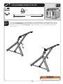
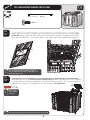
9.6
SEC
9.6
After aligning the holes in the Roof Panel Domed for Skylight AssemblyWITHTHOSEINTHE7ALL0ANELS4RUSSAND'ABLE
secure the Roof Panel for Domed Skylight to the shed using the required hardware. Then, secure a Roof Panel
!'1TOTHEREAROFTHESHED!REGULAR2OOF0ANELONLYUSESONERoof Support (AFL).
AGQ
!
Note: Use only a
hand screwdriver
for this step.
!
Note: Ensure the ridge in the bottom of the Roof Panel fits into the top of the wall.
61
SEC
TOOLS AND HARDWARE REQUIRED FOR THIS PAGE
9
(Not actual size) AFLX
ADZX
SEC
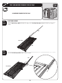
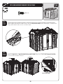
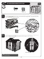
9.7
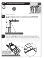
!TTACHA3IDE'ABLE!SSEMBLYTOTHELEFTSIDEOFTHESHEDANDSECUREWITHFOURTEEN1/4” x 5/8” Pan-Head Screws
(ADZ) as you did in steps 9.1 - 9.2. Follow steps 9.3 - 9.6 to install the Left Angled Truss Assembly, a Roof Panel for Domed
Skylight Assembly, Roof Panel (AGQ), and Roof Supports (AFL) on the left side of the shed.
AGQ
SEC
9.8
Set the back end of the Center Truss Assembly into the notch in the center of the rear Wall and the front, angled
ends into the Left and Right Angled Truss Assemblies.
Angled Arms
62
SEC
TOOLS AND HARDWARE REQUIRED FOR THIS PAGE
9
(Not actual size) AFLX
7/16”
ADJ (x4)
ADZX
AQY (x4)
SEC
9.9
SEC
With the front arms of the Center Truss Assembly in the angled arms of the Left and Right Angled Truss
Assemblies, secure the Center Truss Assembly to the Left and Right Angled Truss Assemblies using the required
hardware. Tighten hardware securely.
AQY
AQY
AQY
9.10
AQY
ADJ
ADJ
ADJ
ADJ
SEC
9.10
Install the remaining Roof Panels (AGQ) and Roof Supports (AFL)TOTHEREAROFTHESHEDUSINGTWENTY1/4” x 5/8”
Pan-Head Screws (ADZ)4HE2OOF0ANELSlTDOWNINSIDETHE4RUSS'UTTER#HANNELS
AGQ
AGQ
AGQ
!
63
Note: Roof Panels butt up against each
other inside the Truss Gutter Channels.
Rear of Shed
SEC
TOOLS AND HARDWARE REQUIRED FOR THIS PAGE
AHPX
SEC
9.11
DOOR & ENTRY GABLE INSTALLATION
Insert the hinge tube of the Left, Front Door Assembly into the left, front Door Hinge Bushing as shown. Ensure
bottom of Hinge fits completely into the Door Hinge Bushing.
!
Note: Ensure that these two holes line up, so
that the Cotter Pin (AHP) can be inserted.
SEC
9.12
Insert a Cotter Pin (AHP) through the Bushing and Door Hinge. Use a pair of pliers to bend the ends of the Cotter
Pins outward. Repeat steps 9.11 & 9.12 for the Right, Front Door Assembly (Notched).
SEC
9.12
AHP
!
Note: Use pliers to bend back the
ends of the Cotter Pin (AHP).
64
9
SEC
TOOLS AND HARDWARE REQUIRED FOR THIS PAGE
9
ADZ (x14)
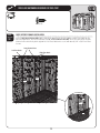
SEC
9.13
While another adult holds the Doors in place, slide the Entry Gable Assembly over the Door Hinges. The tops of the
HINGESWILLlTINTOTHEHOLESONEACHENDOFTHE'ABLE
SEC
9.14
Attach the Upper Left and Right Front Gable Roof Panels (BDT & BDU) using seven (7) 1/4” x 5/8” Pan-Head Screws (ADZ)
per Panel at the locations indicated.
BDT
BDU
BDU
Interior Upward View
65
SEC
TOOLS AND HARDWARE REQUIRED FOR THIS PAGE
9
ADZ (x14)
SEC
9.15
Align the holes in the Lower Left Front Gable Roof Panel (BDR)WITHTHOSEINTHE!NGLED4RUSSAND&RONT'ABLE
Assemblies and secure with the required hardware. Repeat this step for the Lower Right Front Gable Roof Panel (BDS).
BDR
9.
SEC
9.16
BDS
BDS
Interior Upward View
66
SEC
TOOLS AND HARDWARE REQUIRED FOR THIS PAGE
ADZ (x10)
AJAX
(Not to scale)
SEC
9.16
Insert two Foam Cubes (AJA) inside the Center Truss Assembly at the location shown. The purpose of the Foam
Cubes is to block light entering at this point.
AJA
SEC
9.17
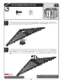
Attach the Entry Gable Roof Cap (BDW) at the locations indicated using the required hardware.
BDW
Interior Upward View
!
Note: Attach the Roof Cap to the Panels and the Gable
at the locations shown.
67
9
SEC
TOOLS AND HARDWARE REQUIRED FOR THIS PAGE
9
ADX (x4)
ARA (x1)
AQZX
(Not to Scale)
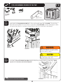
SEC
Loosely attach the Entry Gable Bracket (AQZ) to the Truss at the location shown with a Screw (ADX). Turn the Entry
'ABLE"RACKETINTOPOSITIONANDUSETHEHOLEASAGUIDEFORTHE1/8” Drill Bit (ARA)#AREFULLYDRILLTHROUGHTHE'ABLE
and into the Door Hinge (be sure that the bit goes into the Hinge Tube but not all the way through).
9.18
Gable
ADX
l
nne
ha
sC
s
Tru
Gable
AQZ
el
nn
s
s
Tru
a
Ch
Door
9.
Door
WARNING
Inside View
Inside View
While performing this step, each person
should use protective eye glasses to help
prevent serious eye injury.
CAUTION
$ONOTDRILLALLTHEWAYTHROUGHTHE'ABLE
Only drill into the Hinge Tube.
SEC
9.19
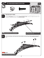
)NSERTTWO#10 x 1/2” Pan-Head Screws (ADX)THROUGHTHE"RACKETANDINTOTHE'ABLEAND$OOR(INGERepeat
steps 9.20 - 9.21 for the other end of the Front Entry Gable.
Tru
ss
Ch
an
ne
l
Gable
Door
!
Inside View
Note: The front of the Panel fits over the Gable.
68
SEC
TOOLS AND HARDWARE REQUIRED FOR THIS PAGE
9
ADZX
SEC
9.20
!
Starting at the left side of your shed, attach the Left End Roof Cap (AGG)TOTHE2OOF0ANELSAND,EFT3IDE'ABLE
Continue moving to the right attaching the Center Roof Caps (AFY). Finally attach the Right End Roof Cap (AFW) to the
2OOF0ANELSAND'ABLE
AFY
AFW
AFY
AFY
Note: Use only a
hand screwdriver
for this step.
AGG
CAUTION
Only hand tighten screws. Do not overtighten.
Overtightening may damage plastic parts and
void warranty.
SEC
9.21
Connect the Roof Caps to each other using 1/4” x 5/8” Pan-Head Screws (ADZ).
ADZ
69
ADZ
SEC
TOOLS AND HARDWARE REQUIRED FOR THIS PAGE
9
ADX X
AEDX
AXXX
(Not to scale)
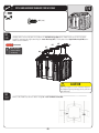
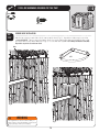
SKYLIGHT INSTALLATION
SEC
Pre-fold Skylight (AHC) before installing. Push folded Skylight up through opening between Roof Caps; open
Skylight; use tabs to pull Skylight down into place. Fasten Skylight in place with #10 x 1” Fender Washers (AED) and
#10 x 1/2” Pan-Head Screws (ADX) (pull down on tabs while inserting screw to provide resistance). Repeat this step for
each Skylight.
9.22
AHC
Note: Use only a
hand screwdriver
for this step.
!
AHC
AHC
AED
ADX
AHC AHC
Pull down on tabs while
inserting screws.
SEC
9.24
SEC
9.23
GABLE CLIP INSERTION
Insert the Truss Hole Inserts (AXX) into the side walls as shown.
AXX
AXX
!
Note: Gable Clip can only be inserted with the arrow
pointing up.
70
SEC
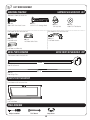
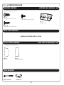
10 SHELF INSTALLATION
HARDWARE REQUIRED
HARDWARE BAG REQUIRED: BHH (x2), BHI (x2)
Hardware shown at actual size
Part shown at 15% of actual size
AIY (x4)
Shelf Bracket
ADZ X
1/4” x 5/8” Pan-Head Screw
ADZ (x8)
1/4” x 5/8” Pan-Head Screw
METAL PARTS KIT REQUIRED: CKP
METAL PARTS REQUIRED
Part shown at 8% of actual size
67 3/4”
AFM (x4)
Shelf Support Channel
PLASTIC PARTS REQUIRED
SMALL PARTS KIT REQUIRED: CQM
Part shown at 4% of actual size
Part shown at 8% of actual size
AFV X
90” Shelf
AFZ X
Corner Shelf
TOOLS REQUIRED
Phillips Screwdriver
Safety Glasses
71
SEC
TOOLS AND HARDWARE REQUIRED FOR THIS PAGE
ADZ (x16)
SEC
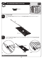
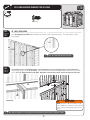
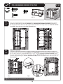
10.1
SHELF SUPPORT CHANNEL INSTALLATION
Insert a Shelf Support Channel (AFM) into the slots in the Wall Panels directly below the Right Truss notch on the
left side of your shed, and secure with four (4) 1/4” x 5/8” Pan-Head Screws (ADZ). Insert a second Shelf Support
Channel in the slot directly to the right of the Left Truss Notch and secure with four (4) 1/4” x 5/8” Pan-Head
Screws.
Insert Channels here.
Left Truss Notch
Right Truss Notch
AFM
AFM
ADZ
AFM
ADZ
72
10
SEC
TOOLS AND HARDWARE REQUIRED FOR THIS PAGE
10
ADZ X
SEC
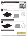
90” SHELF INSTALLATION
10.2
Set a Shelf Support Bracket (AIY) into the slots of each of the Shelf Support Channels. The slots must be at the
same height.
AIY
AIY
!
Note: Insert Shelf Support Bracket at an angle.
SEC
10.3
Fold up flaps on the end of 90” Shelf (AFV). Set Shelf on Brackets with indentations toward wall, and secure with
six (6) 1/4” x 5/8” Phillips Pan-Head Screws (ADZ). Repeat this section for the second 90” Shelf for the right side of the shed.
AFV
ADZ
ADZ
ADZ
Upward view
WARNING
4HEWEIGHTLIMITFORAv3HELFISLBPERv
section of Wall Panel. Failure to heed this warning
could result in property damage and/or personal
injury.
!
Note: There are only holes for screws along front side of the Shelf (front is labeled “Front” on underside of Shelf).
73
SEC
TOOLS AND HARDWARE REQUIRED FOR THIS PAGE
ADZ (x8)
SEC
10.4
CORNER SHELF INSTALLATION
Note the top set of pre-made holes in the corners of the shed (Fig. 1). Any of these holes may be used for
a Corner Shelf (AFZ). Fold up edges of a Corner Shelf. Line-up the holes in the Corner Shelf with the top set of
PREMADEHOLESINANYCORNER7ALL0ANEL&IG3ECUREWITHFOUR1/4” x 5/8” Phillips Pan-Head Screws (ADZ).
Repeat this step for the second Corner Shelf.
Holes
AFZ
Fig. 1
WARNING
The weight limit for a Corner Shelf is 10 lb. per
Shelf. Failure to heed this warning could result in
property damage and/or personal injury.
Fig. 2
74
10
SEC
11 WINDOW INSTALLATION
HARDWARE REQUIRED
HARDWARE BAG REQUIRED: BEI
Hardware shown at actual size
ADZ (x4)
1/4” x 5/8” Pan-Head Screw
ADY (x1)
Xv0AN(EAD3CREW
AISX
Window Latch
ADWX
Xv0AN(EAD3CREW
METAL PARTS REQUIRED
NO METAL PARTS REQUIRED FOR THIS SECTION
PLASTIC PARTS REQUIRED
SMALL PARTS KIT REQUIRED: CQM
Part shown at 4% of actual size
AHE (x1)
Window
BDVX
Half-Wall Window
TOOLS REQUIRED
Phillips Screwdriver
Safety Glasses
75
SEC
TOOLS AND HARDWARE REQUIRED FOR THIS PAGE
11
ADWX
ADY (x1)
AISX
ADZ (x4)
SEC
11.1
Remove the plastic protective film from both sides of the Window for Half-Window Wall Panel (BDV) and attach the
Window for Half-Window Wall Panel to the Right Half-Window Wall Panel using fourteen (14) #10 x 3/4” Pan-Head
Screws (ADW). Repeat this step for the Left Half-Window Wall Panel.
ADW
ADW
BDV
BDV
ADW
SEC
11.2
WINDOW INSTALLATION
Remove the protective plastic film from both sides of the Window (AHE) and slide the Window into the grooves along
the sides of the opening in the Window Wall Panel (Fig. 1). Insert the #10-24 x 3/8” Pan-Head Screw (ADY) into the
HOLEATTHEBOTTOMOFTHE7INDOW&IGUNTILmUSH!TTACHAWindow Latch (AIS) above each corner of the Window
as shown. When tightening the 1/4” x 5/8” Pan-Head Screws (ADZ)ENSURETHE7INDOW,ATCHESSLIDEFREELY&IG
Do not overtighten.
ADY
AHE
AIS
Fig. 1
!
ADZ
ADW
Fig. 2
Fig. 3
Note: Insert Window with bent edge at top and pointing away from the wall.
76
12
SMALL PARTS BOX REQUIRED: BUH
77
12
12.1
12.2
78
SEC
13
FINAL STEPS
HARDWARE REQUIRED
NO HARDWARE REQUIRED FOR THIS SECTION
METAL PARTS REQUIRED
NO METAL PARTS PROVIDED FOR THIS SECTION
PLASTIC PARTS REQUIRED
NO PLASTIC PARTS REQUIRED FOR THIS SECTION
TOOLS REQUIRED
Rubber Mallet
SMALL PARTS BOX REQUIRED: BUH
AIX (x4)
Wood Shim (Included)
Safety Glasses
79
SEC
TOOLS AND HARDWARE REQUIRED FOR THIS PAGE
13
NO HARDWARE PROVIDED FOR THIS STEP
AIX (x4)
SEC
DOOR ALIGNMENT
13.1
In some cases, the Doors may not completely line up at the top (fig. 1). When this happens, identify which side
is higher and use a Wood Shim (AIX)TOSLIGHTLYRAISETHEBACKCORNEROFTHEHIGHSIDEUNTIL$OORSLINEUPlG
If Doors need further adjustment, insert another Shim under the front corner opposite of the first Shim. If the
doors still need further adjustment, stack additional Shims (one at a time) alternating between the back and front
Shims. After Doors are aligned, cut off any portion of wood Shim that is still exposed. From inside the Shed,
drive a 1” nail through the floor into the Shim to hold it in place. If you’ve anchored you shed, tighten all anchoring
hardware now.
High Side
High side
Low side
Second
Shim
Fig. 2
Fig. 1
!
Note: Shim should be placed at the corner, running
directly under one wall.
80
First Shim
Back Corner
CLEANING & CARE
12
Congratulations on your Lifetime® product purchase. By following the instructions below, your new Lifetime product should
provide you with years of service and enjoyment.
Cleaning and Care
The polyethylene panels are stain- and solvent-resistant. Most stains can be removed, using a mild soap and a soft-bristled
brush. Abrasive cleaning materials may scratch the plastic and are not recommended. Repair scratches or rust spots on
the metal by sanding the affected area lightly; using a rust preventative spray primer; and finally, spraying with a high-gloss
spray enamel paint. Avoid placing a direct heat source on or near surfaces unless using a heat barrier.
81
LIFETIME OUTDOOR SHED EQUIPMENT
10-YEAR LIMITED FACTORY WARRANTY
THE MANUFACTURER RESERVES THE RIGHT TO MAKE SUBSTITUTIONS TO WARRANTY CLAIMS IF PARTS ARE UNAVAILABLE OR OBSOLETE.
1. Lifetime outdoor sheds are warranted to the original purchaser to be free from defects in material or workmanship
FORAPERIODOFTENYEARSFROMTHEDATEOFORIGINALRETAILPURCHASE4HEWORDhDEFECTSvISDElNEDASIMPERFECTIONSTHAT
impair the use of the product. Defects resulting from misuse, abuse or negligence will void this warranty. This warranty
does not cover defects due to improper installation, alteration or accident. This warranty does not cover damage caused
BYVANDALISMRUSTINGhACTSOFNATUREvORANYOTHEREVENTBEYONDTHECONTROLOFTHEMANUFACTURER
4HISWARRANTYISNONTRANSFERABLEANDISEXPRESSLYLIMITEDTOTHEREPAIRORREPLACEMENTOFDEFECTIVEPRODUCT)FTHE
product is defective within the terms of this warranty, Lifetime Products, Inc. will repair or replace defective parts at
no cost to the purchaser. Shipping charges to and from the factory or distribution center are not covered and are the
responsibility of the purchaser. Labor charges and related expenses for removal, installation or replacement of the
shed or its components are not covered under this warranty.
4HISWARRANTYDOESNOTCOVERSCRATCHINGORSCUFlNGOFTHEPRODUCTTHATMAYRESULTFROMNORMALUSAGE)NADDITION
defects resulting from intentional damage, negligence, unreasonable use or hanging from the truss will void this
warranty.
4. Liability for incidental or consequential damages is excluded to the extent permitted by law. While every attempt is
made to embody the highest degree of safety in all equipment, freedom from injury cannot be guaranteed. The user
assumes all risk of injury resulting from the use of this product. All merchandise is sold on this condition, and no
representative of the company may waive or change this policy.
5. This product is not intended for institutional or commercial use; Lifetime Products, Inc. does not assume any liability for
such use. Institutional or commercial use will void the warranty.
6. This warranty is expressly in lieu of all other warranties, expressed or implied, including warranties of merchantability
or fitness for use to extent permitted by Federal and state law. Neither Lifetime Products, Inc., nor any representative
assumes any other liability in connection with this product. This warranty gives you specific legal rights, and you may
also have other rights which vary from state to state.
PLEASE INCLUDE YOUR DATED SALES RECEIPT AND PHOTOGRAPHS OF DAMAGED PARTS.
2%0/2402/$5#4$%&%#43).72)4).'4/
Lifetime Products, Inc., PO Box 160010 Clearfield, UT 84016-0010
ORCALL-&AMTOPM-34
REGISTER YOUR PRODUCT FOR QUICKER CUSTOMER SERVICE.
6ISITWWWLIFETIMECOMORCALLTOREGISTERYOURPRODUCTTODAY
FOR INTERNATIONAL WARRANTY CLAIMS:
All warranty claims must be accompanied by a sales receipt. Report all warranty claims in writing to your regional sales
support representative. Please include your dated sales receipt and photographs of damaged parts.
To Identify the representative for your region — Please visit: www.lifetime.com/international
www.lifetime.com
82
ENHANCE YOUR LIFETIME® PURCHASE BY ADDING ACCESSORIES OR OTHER GREAT PRODUCTS
To purchase accessories or other Lifetime Products, visit us at:
www.lifetime.com
Or call: 1-800-424-3865
83