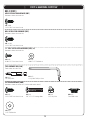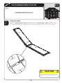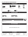
1
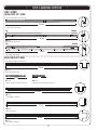
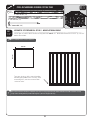
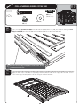
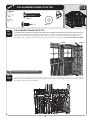
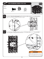
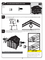
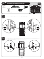
OUTDOOR STORAGE
MODEL N° 6417
Co
py
OWNER’S MANUAL
Keep this Identification Number in case you need to contact our Customer Service Department.
1
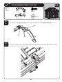
IMPORTANT! PLEASE READ BEFORE BEGINNING ASSEMBLY
Dear Valued Customer,
We would like to congratulate you on your purchase of a Lifetime© Outdoor Storage Shed! We are
confident that you have made the perfect choice and you will be very pleased with your new storage
solution.
Lifetime© Outdoor Storage is part of the family of products created and manufactured by Lifetime®
Products, Inc. Like all of our products, you can be assured that the quality of your Lifetime Outdoor
Storage Shed is the best in the world! And, we back that quality up by offering the best warranty in the
business – A 10-year warranty that fully covers the Shed!
py
All of our Sheds are built with the highest-quality steel and high-density polyethylene (HDPE) parts. The
design and construction of our steel-reinforced double-Wall Panels is second to none. All of our exposed
steel parts and gables are powder coated and we use high-density polyethylene plastic. What makes
polyethylene so special? It has superior strength and durability, and, it won’t crack or degrade outdoors.
So now that you know the quality you are getting in a Lifetime Outdoor Storage Shed, please take the
time to READ THIS INSTRUCTION MANUAL!
We have taken great care in providing the best possible form of instructions to help you put your new
Outdoor Storage Shed together. Before you get started, PLEASE read the following preparation tips to
help you get started!
We can assure you, your construction experience will be a lot more enjoyable if you do!
Co
PREPARATION TIPS:
s 4HE lRST STEP IS SIMPLEx 2%,!8 9OU HAVE MADE A GREAT PURCHASE BUT 2OME WAS NOT BUILT IN A
day. Plan to spend a good part of your weekend putting together your fine Outdoor Storage Shed. Our
PHILOSOPHY IS IF IT COMES TOGETHER QUICKLY AND EASILY IT SURELY WILL COME APART QUICKLY AND EASILY 9OUR
Lifetime© Outdoor Storage Shed will surely last a long, long time, if you are patient, and take all the time
necessary to put it together as we have instructed.
s 'RAB A FRIEND TO JOIN IN ON THE FUN 4HIS IS NOT A ONE PERSON ENDEAVOR 7E HAVE FOUND THAT NOT ONLY WILL
things go smoother if you have two or more people participating in the construction of the Shed, but it
will go quicker as well. So, the more the merrier!
s -AKE SURE YOU HAVE ALL THE TOOLS NECESSARY FOR CONSTRUCTING YOUR NEW 3HED 4HERE IS A h4OOLS 2E
quired For This Assembly” list on page five of this Owner’s Manual.
s 4HE PLASTIC PIECES OF YOUR 3HED MAY BECOME DAMAGED BY OVER TIGHTENING THE SCREWS 4O AVOID THIS
damage, we strongly recommend the use of a low-powered power screwdriver or a drill that has an
adjustable clutch that is set on a low-torque setting. If neither is available, use a hand screwdriver. If a
HAND SCREWDRIVER IS ALL YOU HAVE TAKE SEVERAL BREAKSx YOUR WRIST WILL NEED IT
s 9OU WILL ALSO NEED TWO SMALL LADDERS WHEN IT COMES TIME TO DO THE ROOF 7/10/2010
INSTRUCTION #1065789 B
2
IMPORTANT! PLEASE READ BEFORE BEGINNING ASSEMBLY
s "EFORE BEGINNING ASSEMBLY REMOVE THE 0ARTS ,IST FROM THE CENTER OF THIS /WNERS -ANUAL AND TAKE AN
inventory of the parts included with your Outdoor Storage Shed. Also, read through the entire instruction manual. It’s always a great practice to get a feel for the flow of the process and to familiarize yourself with the parts involved. But, try not to get ahead of yourself and start the process out of order.
s &/,,/7 4(% ).3425#4)/.3 ). /2$%2 %VERYTHING GOES TOGETHER IN A CERTAIN ORDER AND WE HAVE
learned what that correct order should be. In our state-of-the-art research and testing facility, we have
painstakingly created these instructions. The order of construction is there for a reason, and some parts
simply will not fit if built out of order. Just follow along with the order in the instructions and everything
will fit together and things will go very smooth.
s 9/52 3(%$ -534 "% "5),4 /. ! ,%6%, 352&!#% )F THE SPOT YOU HAVE CHOSEN TO PLACE YOUR
wonderful new Outdoor Storage Shed is not level, the Shed will not assemble correctly! We recommend
A CONCRETE PATIO A WOOD PLATFORM OR CREATING A PAD WITH PEA GRAVEL 9OUR 3HED IS MEANT TO LAST A LIFE
time, so provide the proper foundation for it before you start to build.
s "EFORE YOU BUILD IT MAKE SURE YOU ARE ALLOWED TO BUILD IT #ONSULT ALL BUILDING CODES AS WELL AS CITY
and county ordinances, to ensure that you do not require a building permit to construct your Outdoor
Storage Shed. Proper building permit documentation may be required in your neighborhood, and it
would be quite unfortunate to learn this after your Outdoor Storage Shed is already built!
Now that you’re ready to begin the construction of your wonderful new Outdoor Storage Shed, step
back, take a deep breath, get yourself a large cold beverage and enjoy yourself. We guarantee that after
spending the right amount of time in building your Shed, you will be able to enjoy it for years to come.
Thanks for choosing Lifetime©, and have fun!
ABOUT LIFETIME PRODUCTS, INC.
Lifetime Products, Inc., has applied innovation and cutting-edge technology in plastics and
metals to create a family of affordable lifestyle products that feature superior strength and
durability. The world’s leading manufacturer of folding tables and chairs, Lifetime was founded in 1986 as the maker of portable basketball systems that revolutionized the industry with
patented technology. With diverse offerings such as outdoor storage sheds and steel utility
trailers, Lifetime continues to develop innovative products that outfit the way you live.
Lifetime makes the things you need for the lifestyle you want. By innovating products in and
around the home, Lifetime simplifies your everyday life and enables you to get the most out
of your free time.
3
REGISTER YOUR LIFETIME PRODUCT TODAY!
There are benefits to registering your Lifetime product. With our new online product registration form, it’s fast and easy! Register with us at www.lifetime.com
and enjoy these great benefits:
s 2ECEIVE EXCLUSIVE MONEY SAVING OFFERS FROM "UY,IFETIMECOM OUR ONLINE STORE AS WELL AS .%7 PRODUCT NOTIlCATIONS AND SPECIAL CLOSEOUT
promotions!
s )N THE UNLIKELY EVENT OF A PRODUCT RECALL OR SAFETY MODIlCATION WE WILL NOTIFY YOU
s 2EGISTERING YOUR PRODUCT GUARANTEES YOU WARRANTY SERVICE )F YOU DO NOT REGISTER YOUR PRODUCT YOUR WARRANTY RIGHTS WILL NOT BE DIMINISHED
But you will need to provide a sales receipt to verify your product purchase date before warranty service will be provided.
LIFETIME’S PROMISE TO YOU:
Maintaining your privacy is our long-standing policy at Lifetime. And you can rest assured that Lifetime will not sell or provide your
personal data to other third parties, or allow them to use your personal data for their own purposes.
We invite you to read our privacy policy at www.lifetime.com
REGISTER today!
**U.S. and Canada customers ONLY**
IF ASSISTANCE IS NEEDED,
DO NOT CONTACT THE STORE!
CALL OUR CUSTOMER SERVICE DEPARTMENT at 1 (800) 225-3865
HOURS: 7:00 a.m. to 5:00 p.m. Monday through Friday (Mountain Standard Time)
**Call, or visit our Web site for Saturday hours**
**For customers outside the U.S. or Canada, please contact the store for assistance.**
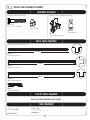
SAFETY INSTRUCTIONS
FAILURE TO FOLLOW THESE WARNINGS MAY RESULT IN SERIOUS INJURY OR
PROPERTY DAMAGE AND WILL VOID WARRANTY.
To ensure safety, do not attempt to assemble this product without following the instructions carefully. Check entire box and inside all
packing material for parts and/or additional instruction material. Before beginning assembly, read the instructions and identify parts
using the hardware identifier and parts list in this document. Proper and complete assembly, use and supervision are essential to
reduce the risk of accident or injury.
s $O NOT USE OR STORE HOT OBJECTS SUCH AS GRILLS BLOWTORCHES WELDING EQUIPMENT ETC NEAR THE PRODUCT
s )F USING A LADDER DURING ASSEMBLY USE EXTREME CAUTION
s 4WO CAPABLE ADULTS ARE REQUIRED FOR ASSEMBLY )T IS ALSO RECOMMENDED THAT A THIRD ADULT FUNCTION AS AN INSTRUCTION READER
Most injuries are caused by misuse and/or not following instructions. Use caution when using this product.
4
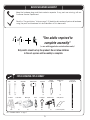
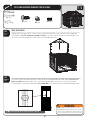
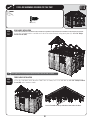
BEFORE BEGINNING ASSEMBLY
Keep the hardware bags and their contents separate. If any parts are missing, call our
Customer Service Department.
2EAD THE h#ONGRATULATIONSv LETTER ON PAGE Identify and inventory all parts and hardware
using the parts and hardware lists and identifiers in this document.
*Two adults required to
complete assembly*
(+ one adult suggested as an instruction reader)
Only adults should set up the product. Do not allow children
in the set-up area until assembly is complete.
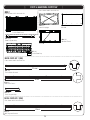
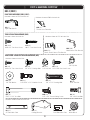
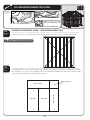
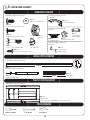
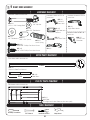
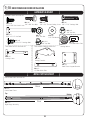
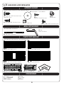
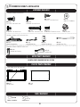
TOOLS REQUIRED FOR ASSEMBLY
7/16"
3/8"
Adjustable
Rubber Mallet
(2)
(1)
(1)
(1)
6’ Ladder
(2)
Box Knife
(1)
Phillips
Screwdriver
3/8" Masonry
Bit
(1)
(1)
Power Drill*
Work Light
Pliers
Flashlight
Hammer Drill*
Safety Glasses
(1)
(1)
(1)
(1)
(1)
(1 for each person)
*See “Screwdriver Notice” on page 7.
5
2" x 4" x 11'
Leveling Board
(1)
REGISTER YOUR LIFETIME PRODUCT TODAY!
There are benefits to registering your Lifetime product. With our new online product registration form, it’s fast and easy! Register with us at www.lifetime.com
and enjoy these great benefits:
s 2ECEIVE EXCLUSIVE MONEY SAVING OFFERS FROM "UY,IFETIMECOM OUR ONLINE STORE AS WELL AS .%7 PRODUCT NOTIlCATIONS AND SPECIAL CLOSEOUT
promotions!
s )N THE UNLIKELY EVENT OF A PRODUCT RECALL OR SAFETY MODIlCATION WE WILL NOTIFY YOU
s 2EGISTERING YOUR PRODUCT GUARANTEES YOU WARRANTY SERVICE )F YOU DO NOT REGISTER YOUR PRODUCT YOUR WARRANTY RIGHTS WILL NOT BE DIMINISHED
But you will need to provide a sales receipt to verify your product purchase date before warranty service will be provided.
LIFETIME’S PROMISE TO YOU:
Maintaining your privacy is our long-standing policy at Lifetime. And you can rest assured that Lifetime will not sell or provide your
personal data to other third parties, or allow them to use your personal data for their own purposes.
We invite you to read our privacy policy at www.lifetime.com
REGISTER today!
**U.S. and Canada customers ONLY**
IF ASSISTANCE IS NEEDED,
DO NOT CONTACT THE STORE!
CALL OUR CUSTOMER SERVICE DEPARTMENT at 1 (800) 225-3865
HOURS: 7:00 a.m. to 5:00 p.m. Monday through Friday (Mountain Standard Time)
**Call, or visit our Web site for Saturday hours**
**For customers outside the U.S. or Canada, please contact the store for assistance.**
SAFETY INSTRUCTIONS
FAILURE TO FOLLOW THESE WARNINGS MAY RESULT IN SERIOUS INJURY OR
PROPERTY DAMAGE AND WILL VOID WARRANTY.
To ensure safety, do not attempt to assemble this product without following the instructions carefully. Check entire box and inside all
packing material for parts and/or additional instruction material. Before beginning assembly, read the instructions and identify parts
using the hardware identifier and parts list in this document. Proper and complete assembly, use and supervision are essential to
reduce the risk of accident or injury.
s $O NOT USE OR STORE HOT OBJECTS SUCH AS GRILLS BLOWTORCHES WELDING EQUIPMENT ETC NEAR THE PRODUCT
s )F USING A LADDER DURING ASSEMBLY USE EXTREME CAUTION
s 4WO CAPABLE ADULTS ARE REQUIRED FOR ASSEMBLY )T IS ALSO RECOMMENDED THAT A THIRD ADULT FUNCTION AS AN INSTRUCTION READER
Most injuries are caused by misuse and/or not following instructions. Use caution when using this product.
6
IMPORTANT NOTICES
Level Surface Notice:
Surface must be leveled before installation. We recommend building a level work space with a concrete
or patio style surface. If the surface is not properly leveled, the Outdoor Shed will not assemble correctly.
Proper surface leveling will save you time in the long run, so please do not ignore this step.
Building Code Notice:
Consult all local building codes, as well as city and county ordinances, to ensure that the construction of the
Outdoor Shed does not require a building permit. Proper building permit documentation may be required in
your neighborhood, and it would be unfortunate to learn this after constructing the Shed.
Screwdriver Notice:
9OU MAY USE A 0HILLIPS HEAD SCREWDRIVER BIT AND A POWER SCREWDRIVER OR DRILL INSTEAD OF A HAND
screwdriver. However, be aware that the plastic pieces of your Shed can be damaged by overtightening of
screws. To avoid damage we strongly recommend the use of a low-powered power screwdriver or a drill that
has an adjustable clutch that is set on a low torque setting. If neither is available, use a hand screwdriver. In
any case use caution to avoid overtightening the screws.
Floor Puncture Notice:
Sharp objects may damage your floor. If resting sharp, heavy objects on your Shed floor, place a block of
wood between the sharp object and floor.
CAUTION:
If more than six (6) inches of snow accumulate on the roof of the shed, carefully remove the snow to avoid
possible roof collapse. While standing on the ground, remove the snow from the roof with a broom or snow
shovel. Do not stand on the roof to remove snow.
Snow Load Kit available from Customer Service for high snow areas.
7
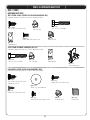
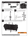
PARTS & HARDWARE LIST
ID
Description
BNH GABLE BRACE & ROOF INSTALLATION HARDWARE
ADZ
1/4” x 5/8” Pan-Head Screw
!%$
X v &ENDER 7ASHER
!#*
X v 0AN (EAD 3CREW
!*!
&OAM #UBE
!$8
X v 0AN (EAD 3CREW
!#&
X v 0AN (EAD 3CREW
!$+
#AP .UT
BOX 1
ID
!')
!'(
!'5
!'6
!'3
!'4
!'%
!&4
AFB
",'
",)
!&&
Description
2IGHT 'ABLE
,EFT 'ABLE
/UTER 2OOF 0ANEL !
/UTER 2OOF 0ANEL "
/UTER &LOOR 0ANEL !
/UTER &LOOR 0ANEL "
%ND 2OOF #AP
v X v 3HELF
Door Brace
%XTENDED $OOR "RACE
#ORNER &RAME "RACKET
'ABLE 4RUSS "RACE
Qty
8
Left Hinge Assembly
2IGHT (INGE !SSEMBLY
Center Hinge Assembly
!&9
!'1
AHB
!'"
AHH
AHD
!('
!'*
!(&
AFL
1
1
BNN METAL PARTS KIT 2
AFQ
!&*
!&.
AFH
!&2
!&'
",(
!&0
",,
",",.
Wall Support Channel
,ONG 6ERTICAL %XTENSION #HANNEL
3HORT 6ERTICAL %XTENSION #HANNEL
TRUSS 'UTTER #HANNEL
#ORNER #HANNEL
4RUSS "RACE #HANNEL
%XTENDED $OOR %ND #HANNEL
4RUSS 3UPPORT 3TRIP
,ONG 'LIDER 4RACK
3HORT 'LIDER 4RACK
'LIDER 4RACK %XTENSION
6
#ENTER 2OOF #AP
#ENTER 2OOF 0ANEL
Roof Panel for Skylight
7ALL 0ANEL
$OMED 3KYLIGHT
Window Wall Panel
7INDOW &RAME
)NNER &LOOR 0ANEL
7INDOW
Roof Support Strip
!&'
AFH
Truss Support Strip
TRUSS 'UTTER #HANNEL
2OOF 4RUSS "RACE
!&0
!&1
Wall Support Channel
2OOF 4RUSS "RACE
TRUSS 'UTTER #HANNEL
4RUSS 3UPPORT 3TRIP
7ALL 3UPPORT #HANNEL
BNB HARDWARE BOX
BGU WINDOW ASSEMBLY & INSTALLATION HARDWARE (x2)
ADZ
1/4” x 5/8” Pan-Head Screw
!$7
X v 0AN (EAD 3CREW
!$8
X v 0AN (EAD 3CREW
!%%
X v &LAT 7ASHER
!#&
X v 0AN (EAD 3CREW
!#"
X v 0AN (EAD 3CREW
!$+
#AP .UT
!#$
X v &LAT (EAD 3CREW
!)6
7INDOW 3TAY "RACKET
!)%
-OUNTED 7INDOW 3TAY
!).
3LIDING 7INDOW 3TAY
AIR
Window Hinge
AIT
Window Latch
AIU
Window Latch Bearing
BEC DOMED SKYLIGHT ASSEMBLY HARDWARE (x2)
!#2
X v #ARRIAGE "OLT
!%%
X v &LAT 7ASHER
!$+
#AP .UT
AHI
Butyl Tape
1
1
14
4
BNK METAL PARTS KIT 2
AFQ
1
1
1
6
BNF METAL PARTS KIT 2
BNL METAL PARTS KIT 1
AFP
AFH
!&'
#ENTER 2OOF #AP
#ENTER 2OOF 0ANEL
Roof Panel for Skylight
$OMED 3KYLIGHT
Window Wall Panel
Wall Panel
7INDOW &RAME
)NNER &LOOR 0ANEL
7INDOW
Roof Support Strip
BNG METAL PARTS KIT 1
BOX 2
!&9
!'1
AHB
!($
!'"
AHH
!('
!'*
!(&
AFL
185
BOX 3
BNM METAL PARTS KIT 1
BLK
"-'
BKZ
Qty
4
BNJ HARDWARE BOX
BOX 4
BNI TRUSS FRAME & WALL SUPPORT INSTALLATION HARDWARE
ADZ
1/4” x 5/8” Pan-Head Screw
!$*
v #AP .UT
!!+
v X v (EX "OLT
AHT
Floor Bracket
!#$
X v &LAT (EAD 3CREW
!$+
#AP .UT
BGV TRUSS FRAME ASSEMBLY HARDWARE (x4)
AIP
Truss Connector
AAK
1/4” x 1.5” Hex Bolt
ADJ
1/4” Cap Nut
!(4
&LOOR "RACKET
AHD
",*
!18
110
8
Wall Panel
#ORNER $OOR &RAME
#ORNER 4RIM
4
4
4
4
1
6
BNO Parts & Hardware Box
!(!
2OOF #AP #OVER
!&5
0EGBOARD 3TRIP
AIZ
14” Shelf Bracket
BHC PEGBOARD STRIP INSTALLATION HARDWARE
!$7
X v 0AN (EAD 3CREW
BHD Tool Clip Assortment
!)(
0EGBOARD * (OOK
!))
0EGBOARD , (OOK
!)*
0EGBOARD 4OOLHOLDER
!)&
0EGBOARD v $OUBLE !RM (OOK
!)'
0EGBOARD $OUBLE !RM (OOK
1
10
10
8
4
PARTS & HARDWARE LIST (CONT.)
ID
Description
BNA GABLE ASSEMBLY HARDWARE (x2)
!'0
,OUVERED 6ENT
AIQ
Vent Screen
!$7
X v 0AN (EAD 3CREW
!%%
X v &LAT 7ASHER
ADZ
1/4” x 5/8” Pan-Head Screw
BMZ GABLE INSTALLATION HARDWARE
!$:
v X v 0AN (EAD 3CREW
BMX WALL INSTALLATION HARDWARE
ADZ
1/4” x 5/8” Pan-Head Screw
BMY 14” SHELF INSTALLATION HARDWARE (x2)
!$8
X v 0AN (EAD 3CREW
!%%
X v &LAT 7ASHER
CGW TOOL HARDWARE BAG
AID
L-Key with Phillips Head
!$#
0HILLIPS "IT
BMW LEFT DOOR HARDWARE
ADZ
1/4” x 5/8” Pan-Head Screw
!"5
v X v #ARRIAGE "OLT
!$*
v #AP .UT
!($EADBOLT ,ATCH
!%"
v &LAT 7ASHER
BMV CENTER DOOR HARDWARE
!$7
X v 0AN (EAD 3CREW
!$8
X v 0AN (EAD 3CREW
!%%
X v &LAT 7ASHER
BLA
Inside Handle
AHZ
Center Handle
"10
v X v #ARRIAGE "OLT
!$*
v #AP .UT
AIA
Center Door Lock Bracket
AIB
Center Door Extended Strike Plate
ADZ
1/4” x 5/8” Pan-Head Screw
AHM
Deadbolt Latch
""(
%ND 0LUG
BMU RIGHT DOOR HARDWARE
ADZ
1/4” x 5/8” Pan-Head Screw
!%%
X v &LAT 7ASHER
!$7
X v 0AN (EAD 3CREW
"11
v X v #ARRIAGE "OLT
!(9
,ATCH 3PRING
AHW
Thumb Lever Extension
!%"
v &LAT 7ASHER
!$*
v #AP .UT
!$"
v X v 3TEEL 3PACER
AIL
Right Door Lock Bracket
AHV
Extended Door Latch
!(8
,ATCH #OVER 0LATE
AIO
Thumb Lever
AIK
Right Handle
BND TRIM INSTALLATION HARDWARE
!#+
X v 0AN (EAD 3CREW
!$8
X v 0AN (EAD 3CREW
!'!
"LACK 0LASTIC #ORNER 4RIM "RACKET
BMH
Metal Corner Trim Bracket
Qty
1
4
116
1
9
1
1
1
1
9
1
ID
Description
BNE DOOR FRAME & DOOR INSTALLATION HARDWARE
!$8
X v 0AN (EAD 3CREW
!#!
v X v #ARRIAGE "OLT
!$*
v #AP .UT
!$:
v X v 0AN (EAD 3CREW
AEB
1/4” Flat Washer
""%
'LIDER 7HEEL
""&
v X Xv X v 3HOULDER 3CREW
!"5
v X v #ARRIAGE "OLT
""'
v X v (EX "OLT
!!6
v *AM .UT
BBJ
4” Floor Strike Plate
BBK
Carriage Bracket
"",
v X v (EX "OLT
""v X v 4HREAD #UTTING 3CREW
BBN
Carriage Latch
!(,
$EAD "OLT 3TRIKE 0LATE
AAU
1/4” Cap Nut
#*2
$OOR &RAME 3UPPORT "RACKET
BNC DOOR WINDOW INSTALLATION HARDWARE
!$:
v X v 0AN (EAD 3CREW
Qty
8
1
1
1
4
BOX 5
!':
!'/
",/
9
1
1
1
1
1
10
9
2IGHT #ENTER $OOR
,EFT $OOR
$OOR 7INDOW
PARTS & HARDWARE IDENTIFIER
BOX 1
Parts shown at 8% of actual size
1000472
Rear View
AGH X
,EFT 'ABLE
1000541
1000470
AGI X
2IGHT 'ABLE
Rear View
1003372
AGU X
Outer Roof Panel A
AGV X
Outer Roof Panel B
61 25/32”
61 25/32”
1000466
1000464
26 1/4”
AFB (x8)
Door Brace
10”
AGT X
Outer Floor Panel B
14 7/16”
AGS X
Outer Floor Panel A
BLG (x1)
Extended Door Brace
AFF X
'ABLE 4RUSS "RACE
Part shown at 15% of actual size
Part shown at 4% of actual
size
1000540
1002315
AGE X
End Roof Cap
AFT X
v X v 3HELF
BLI X
Corner Frame Bracket
10
PARTS & HARDWARE IDENTIFIER
BOX 1 (CONT.)
METAL PARTS KIT 1 [BNM]
Parts shown at 8% of actual size
77 13/16”
BKZ (x1)
Center Hinge Assembly
Top
Bottom
BMG (x1)
Right Hinge Assembly
78 1/4”
Top
Bottom
BLK (x1)
Left Hinge Assembly
78 1/4”
METAL PARTS KIT 2 [BNN]
Parts shown at 8% of actual size
79 1/2”
AFQ (x6)
Wall Support Channel
25 1/2”
AFJ X
Long Vertical Extension Channel
16 1/2”
AFN X
Short Vertical Extension Channel
71 11/16”
AFH X
4RUSS 'UTTER #HANNEL
77 1/2”
AFR X
Corner Channel
79 1/2”
AFG (x1)
Truss Brace Channel
11
PARTS & HARDWARE IDENTIFIER
BOX 1 (CONT.)
1 1/2”
Parts shown at 8% of actual size
77 13/16”
BLH X
Extended Door End Channel
BLM (x1)
3HORT 'LIDER 4RACK
20 1/8”
13”
AFP X
Truss Support Strip
69 1/4”
BLL (x1)
,ONG 'LIDER 4RACK
57”
BLN (x1)
'LIDER 4RACK #HANNEL
BOX 2
Parts shown at 4% of actual size
1015533
AHB (x1)
Roof Panel for Skylight
1000272
AHD X
Wall Panel
62 3/16 ”
100XXXX
AHH (x1)
Window Wall Panel
AGJ (x4)
Inner Floor Panel
12
1000463
PARTS & HARDWARE IDENTIFIER
Parts shown at 8% of actual size
BOX 2
Parts shown at 4% of actual size
AGB (x1)
Domed Skylight
1000476
AHF X
Window
AGQ X
Center Roof Panel
28 7/8”
AFL (x14)
Roof Support Strip
AHG X
Window Frame
1004595
1021070
AFY X
Center Roof Cap
METAL PARTS KIT 1 [BNL]
Parts shown at 8% of actual size
71 11/16”
AFH (x4)
4RUSS 'UTTER #HANNEL
79 1/2”
AFG X
Roof Truss Brace
20 1/8”
AFP (x4)
Truss Support Strip
METAL PARTS KIT 2 [BNK]
Part shown at 8% of actual size
79 1/2”
AFQ (x4)
Wall Support Channel
13
PARTS & HARDWARE IDENTIFIER
BOX 2 (CONT.)
HARDWARE BOX [BNJ]
TRUSS FRAME & WALL SUPPORT INSTALLATION HARDWARE [BNI]
Hardware shown at actual size (*Unless otherwise noted)
ADZ (x110)
1/4” x 5/8” Pan-Head Screw
AAK X
v X v (EX "OLT
ADJ X
1/4” Cap Nut
ACD (x4)
X v &LAT (EAD 3CREW
ADK (x4)
#AP .UT
AHT (x8)*
Floor Bracket
TRUSS FRAME ASSEMBLY HARDWARE [BGV] (x4)
Hardware shown at actual size (*Unless otherwise noted)
AAK (x10)
v X v (EX "OLT
AHT X
Floor Bracket
ADJ (x10)
1/4” Cap Nut
AIP (x1)*
Truss Connector
GABLE BRACE & ROOF INSTALLATION HARDWARE [BNH]
Hardware shown at actual size (*Unless otherwise noted)
ADZ (x185)
1/4” x 5/8” Pan-Head Screw
(Not all are used)
ACJ (x16)
X v 0AN (EAD 3CREW
AED (x16)
X v &ENDER 7ASHER
ADX (x4)
X v 0AN (EAD 3CREW
ACF (x1)
X v 0AN (EAD 3CREW
14
ADK (x1)
#AP .UT
AJA X
Foam Cube
PARTS & HARDWARE IDENTIFIER
BOX 3
Parts shown at 4% of actual size
1000476
1015533
AGQ (x1)
Center Roof Panel
AHB (x1)
Roof Panel for Skylight
100XXXX
AHD (x1)
Wall Panel
AHH (x1)
Window Wall Panel
62 3/16 ”
1000463
1000272
AGJ X
Inner Floor Panel
Parts shown at 8% of actual size
AGB (x1)
Domed Skylight
1004595
AHF X
Window
AHG X
Window Frame
28 7/8”
AFL (x6)
Roof Support Strip
1021070
AFY (x1)
Center Roof Cap
15
PARTS & HARDWARE IDENTIFIER
BOX 3 (CONT.)
METAL PARTS KIT 1 [BNG]
Parts shown at 8% of actual size
71 11/16”
AFH X
4RUSS 'UTTER #HANNEL
79 1/2”
AFG (x1)
Roof Truss Brace
METAL PARTS KIT 2 [BNF]
Part shown at 8% of actual size
79 1/2”
AFQ X
Wall Support Channel
20 1/8”
AFP X
Truss Support Strip
HARDWARE BOX [BNB]
WINDOW ASSEMBLY & INSTALLATION HARDWARE [BGU] (x2)
Hardware shown at actual size
ADZ (x4)
1/4” x 5/8” Pan-Head Screw
ADW (x4)
X v 0AN (EAD 3CREW
AEE X
X v &LAT 7ASHER
ACF X
X v 0AN (EAD 3CREW
ACD X
X v &LAT (EAD 3CREW
(Not used in this model)
ADK X
#AP .UT
(Not used in this model)
16
ADX X
X v 0AN (EAD 3CREW
ACB (x4)
X v 0AN (EAD 3CREW
PARTS & HARDWARE IDENTIFIER
BOX 3 (CONT.)
WINDOW ASSEMBLY & INSTALLATION HARDWARE [BGU] (x2) (CONT.)
0ARTS SHOWN AT OF ACTUAL SIZE
AIR (x4)
Window Hinge
AIN X
Sliding Window Stay
AIE X
Mounted Window Stay
Parts shown at 50% of actual size
AIV X
Window Stay
Bracket
AIT (x4)
Window Latch
AIU (x4)
Window Latch Bearing
DOMED SKYLIGHT ASSEMBLY HARDWARE BAG [BEC] (x2)
Hardware shown at actual size (*unless otherwise noted)
ACR X
X v #ARRIAGE "OLT
ADK X
#AP .UT
AEE X
X v &LAT 7ASHER
BOX 4
Part shown at 4% of actual size
1000272
AHD (x6)
Wall Panel
Part shown at 4% of actual size
78 13/16”
AQX (x4)
Corner Trim
78 1/4”
BLJ X
Corner Door Frame
17
AHI (x1)
Butyl Tape
PARTS & HARDWARE IDENTIFIER
BOX 4 (CONT.)
PARTS & HARDWARE BOX [BNO]
Parts shown at 15% of actual size
AFU X
Pegboard Strip
AIZ (x4)
14” Shelf Bracket
AHA X
Roof Cap Cover
PEGBOARD STRIP INSTALLATION HARDWARE [BHC]
Hardware shown at actual size
TOOL CLIP ASSORTMENT [BHD]
Parts shown at 50% of actual size
ADW (x10)
X v 0AN (EAD 3CREW
AIJ X
Toolholder
AIH X
J-HOOK
AIF (x1)
v $OUBLE !RM (OOK
AIG (x1)
4” Double-Arm Hook
AII X
L-Hook
GABLE ASSEMBLY HARDWARE [BNA] (x2)
Hardware shown at actual size
ADW (x5)
X v 0AN (EAD 3CREW
AEE (x5)
X v &LAT 7ASHER
AGP (x1)
Louvered Vent
ADZ (x4)
1/4” x 5/8” Pan-Head Screw
18
AIQ (x1)
Vent Screen
PARTS & HARDWARE IDENTIFIER
BOX 4 (CONT.)
GABLE INSTALLATION HARDWARE [BMZ]
Hardware shown at actual size
ADZ X
1/4” x 5/8” Pan-Head Screw
WALL INSTALLATION HARDWARE [BMX]
Hardware shown at actual size
ADZ (x116)
1/4” x 5/8” Pan-Head Screw
14” SHELF INSTALLATION HARDWARE [BMY] (x2)
Hardware shown at actual size
ADX (x4)
X v 0AN (EAD 3CREW
AEE (x4)
X v &LAT 7ASHER
TOOL HARDWARE BAG [CGW]
Tools shown at actual size
ADC (x1)
0HILLIPS "IT
AID (x1)
L-Key with Phillips Head
LEFT DOOR HARDWARE [BMW]
Hardware shown at actual size (*Unless otherwise noted)
ADZ (x9)
1/4” x 5/8” Pan-Head Screw
ADJ X
1/4” Cap Nut
ABU X
v X v #ARRIAGE "OLT
AEB X
1/4” Flat Washer
19
AHM X
Dead Bolt Latch
PARTS & HARDWARE IDENTIFIER
BOX 4 (CONT.)
CENTER DOOR HARDWARE [BMV]
Hardware shown at actual size
ADW X
X v 0AN (EAD 3CREW
AEE (x1)
X v &LAT 7ASHER
BQP X
1/4” x 1 1/4” Carriage Bolt
ADX X
X v 0AN (EAD 3CREW
BBH X
End Plug
ADZ (x9)
1/4” x 5/8” Pan-Head Screw
Hardware shown at 50% of
actual size
Hardware shown at 15% of
actual size
ADJ X
1/4” Cap Nut
(ARDWARE SHOWN AT OF ACTUAL SIZE
AIA (x1)
Center Door Lock Bracket
AHZ (x1)
Center Handle
BBI (x1)
Inside Handle
AHM (x1)
Dead Bolt Latch
AIB (x1)
Center Door Extended Strike Plate
RIGHT DOOR HARDWARE [BMU]
Hardware shown at actual size
ADZ (x9)
1/4” x 5/8” Pan-Head Screw
AEE X
X v &LAT 7ASHER
ADW (x4)
X v 0AN (EAD 3CREW
ADB X
v X 3TEEL 3PACER
BQQ X
v X v #ARRIAGE "OLT
AHY (x1)
Latch Spring
AEB X
1/4” Flat Washer
ADJ X
1/4” Cap Nut
0ARTS SHOWN AT OF ACTUAL SIZE
AHV (x1)
Extended Door Latch
AHX (x1)
Latch Cover Plate
AIL (x1)
Right Door Lock Bracket
20
AIO (x1)
Thumb Lever
PARTS & HARDWARE IDENTIFIER
BOX 4 (CONT.)
RIGHT DOOR HARDWARE [BMU] (CONT.)
Hardware shown at 15% of actual size
AIK (x1)
Right Door Handle
Hardware shown at 50% of actual size
AHW (x1)
Thumb Lever Extension
TRIM INSTALLATION HARDWARE [BND]
(ARDWARE SHOWN AT OF ACTUAL SIZE
Hardware shown at actual size
ADX X
X v 0AN (EAD 3CREW
ACK (x4)
X v 0AN (EAD 3CREW
BMH (x10)
AGA X
Metal Corner Trim Bracket
Black, Plastic Corner Trim Bracket
DOOR FRAME & DOOR INSTALLATION HARDWARE [BNE]
Hardware shown at actual size
ADX (x4)
X v 0AN (EAD 3CREW
AEB (x8)
1/4” Flat Washer
ACA (x8)
v 8 v #ARRIAGE "OLT
ADJ X
1/4” Cap Nut
BBF X
v Xv X v 3HOULDER 3CREW
AAU (x4)
1/4” Cap Nut
ADZ X
1/4” x 5/8” Pan-Head Screw
ABU (x6)
v X v #ARRIAGE "OLT
BBM (x4)
v X v 4HREAD #UTTING 3CREW
BBG (x1)
v X v (EX "OLT
AAV X
5/16” Jam Nut
BBL (x6)
v X v (EX "OLT
Hardware shown at 50% of actual size
BBJ (x1)
4” Floor Strike Plate
AHL X
Dead Bolt Strike Plate
BBK (x1)
Carriage Bracket
21
BBE X
'LIDER 7HEEL
PARTS & HARDWARE IDENTIFIER
BOX 4 (CONT.)
DOOR FRAME & DOOR INSTALLATION HARDWARE [BNE] (CONT.)
Hardware shown at 50% of actual size
CJR X
Door Frame Support Bracket
(ARDWARE SHOWN AT OF ACTUAL SIZE
BBN (x1)
Carriage Latch
DOOR WINDOW INSTALLATION HARDWARE [BNC]
Hardware shown at actual size
ADZ X
1/4” x 5/8” Pan-Head Screw
BOX 5
Parts shown at 4% of actual size
AGZ X
2IGHT #ENTER $OORS
AGO (x1)
Left Door
BLO X
Door Window
22
SEC
TOOLS AND HARDWARE REQUIRED FOR THIS PAGE
1
Concrete (1 cu. yd.)
SEC
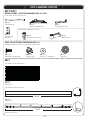
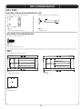
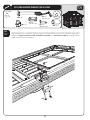
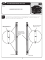
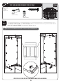
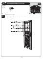
SITE PREPARATION - CONCRETE PLATFORM PREPARATION
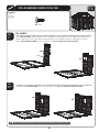
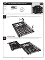
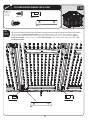
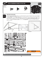
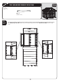
1.1
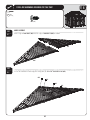
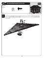
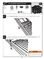
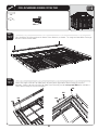
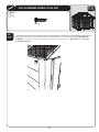
The actual dimensions of your shed (at its widest and longest points) are 11’ x 11’. Be sure to select a site that
will accommodate these measurements. The base of the shed is slightly smaller than this, so you will need to
CREATE A LEVEL SURFACE THAT IS v X vv 4HE mOOR OF THE SHED WILL HAVE A SLIGHT OVERHANG TO HELP
prevent water from pooling under the floor. We recommend using a level concrete or patio style surface. This will
provide the best long-term performance for your shed.
!
Note: Shed Extension Kits are available for this shed. Please consider possible shed expansion when planning the site for your shed. See inside the
back cover of this manual for information on ordering Extension Kits.
132”
132”
123 1/2”
132”
123 1/2”
132”
!
Note: Surface must be leveled before installation. If the surface is not properly leveled, the Outdoor Shed will not assemble or function correctly.
Proper surface leveling will save you time in the long run, so please do not ignore this step.
23
SEC
TOOLS AND HARDWARE REQUIRED FOR THIS PAGE
1
2” x 4” x 120 1/2” (x9)
2” x 4” x 123 1/2” X
16d 3” Common Nail X
SEC
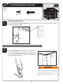
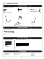
ALTERNATIVE SITE PREPARATION: OPTION 1 - WOOD PLATFORM ASSEMBLY
1.2
Ensure you use lumber that is treated and approved for outdoor USE "UILD OUTSIDE FRAME TO v BY v
outside dimensions.
!
Note: All lumber must be rated for outdoor use.
123 1/2”
123 1/2”
To ensure studs are in the correct location
for nailing to plywood in the next step, start
measuring here, and then measure from
center to center.
16”
!
16”
16”
16”
16”
16”
16”
Note: Surface must be leveled before installation. If the surface is not properly leveled, the Outdoor Shed will not assemble or function correctly.
Proper surface leveling will save you time in the long run, so please do not ignore this step.
24
SEC
TOOLS AND HARDWARE REQUIRED FOR THIS PAGE
1
27 1/2” x 96” x 3/4” Treated Plywood X
8d 1 1/2” Common Nail X
48” x 96” x 3/4” Treated Plywood X
27 1/2” x 27 1/2” x 3/4” Treated Plywood (x1)
SEC
ALTERNATIVE SITE PREPARATION: OPTION 1 - WOOD PLATFORM ASSEMBLY (CONT)
1.3
Square up the frame by measuring from corner to corner. Measurement A should equal Measurement B.
!
Note: All lumber must be rated for outdoor use.
B
A
SEC
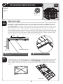
Cut Plywood into sizes called for on previous page. Arrange the Plywood according to the diagram and nail into
PLACE WITH D X v NAILS 0LACE PLATFORM IN THE DESIRED LOCATION )F PLATFORM DOES NOT REST LEVEL ON THE GROUND
build up low points with loose dirt until platform is stable.
27 1/2” x 27 1/2”
96” x 27 1/2”
96” x 48”
96” x 48”
25
96” x 27 1/2”
1.4
SEC
TOOLS AND HARDWARE REQUIRED FOR THIS PAGE
1
2” x 4” x 123 1/2” X
2” x 6” x 117” X
L-Bracket (x4)
Pea Gravel #UBIC &EET
8d 1 1/2” Common Nail (x16)
SEC
1.5
!
!
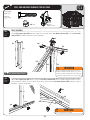
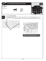
ALTERNATIVE SITE PREPARATION: OPTION 2 - FILLED WOOD FRAME ASSEMBLY
#UT OUTSIDE FRAME TO v BY v OUTSIDE DIMENSIONS ,AY BOARDS mAT SO WIDEST PART FACES UP
Ensure frame is level. Square up the frame by measuring from corner to corner. Measurement A should equal
Measurement B. Nail an L-Bracket on each corner of the frame with 8d nails. Place platform in the desired
LOCATION )F PLATFORM DOES NOT REST LEVEL ON THE GROUND BUILD UP LOW POINTS WITH LOOSE DIRT OR h0EAv GRAVEL UNTIL
platform is stable.
Note: Whenever possible you should use the surfaces described on Page 7.
Note: All lumber must be rated for outdoor use.
123 1/2”
123 1/2”
B
2” x 6” Boards
A
SEC
1.6
SEC
Once all boards are level and do not wobble,
PACK h0EAv GRAVEL AROUND THE OUTSIDE OF THE
frame, and slope away from frame.
1.7
v X v X ,EVELING "OARD X
26
.OW lLL THE INSIDE OF THE FRAME WITH h0EAv
gravel. Use a leveling board to scrape off extra
fill material and to level the surface.
SEC
2
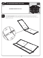
FLOOR ASSEMBLY
HARDWARE REQUIRED
NO HARDWARE PROVIDED FOR THIS SECTION
METAL PARTS REQUIRED
NO METAL PARTS REQUIRED FOR THIS SECTION
PLASTIC PARTS REQUIRED
Parts shown at 4% of actual size
61 25/32”
62 3/16 ”
AGS X
Outer Floor Panel A
61 25/32”
AGJ (x6)
Inner Floor Panel
1000463
AGT X
Outer Floor Panel B
TOOLS REQUIRED
Phillips Screwdriver
Hammer Drill
Safety Glasses
27
3/8” Masonry Bit
SEC
TOOLS AND HARDWARE REQUIRED FOR THIS PAGE
2
NO HARDWARE REQUIRED FOR THIS PAGE
SEC
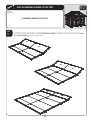
FLOOR PANEL ASSEMBLY
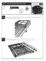
2.1
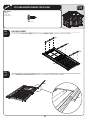
Hold one (1) Outer Floor Panel “B” (AGT) at an angle against one (1) Outer Floor Panel “A” (AGS) so the tabs on Panel
h"v lT UNDERNEATH 0ANEL h!v AND THE TABS ON 0ANEL ! lT UNDERNEATH 0ANEL h"v 4HEN LAY 0ANEL h"v mAT
AGT
AGS
CAUTION
Sharp objects may damage your floor. If resting
sharp, heavy objects on your shed floor, place
a block of wood between the sharp object and
floor.
28
SEC
TOOLS AND HARDWARE REQUIRED FOR THIS PAGE
2
NO HARDWARE REQUIRED FOR THIS PAGE
SEC
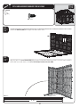
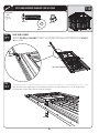
2.2
Hold an Inner Floor Panel (AGJ) at an angle against another Inner Floor Panel so the tabs on each Panel fit
underneath the other Panel. Then, lay the Panel flat. Connect the Inner Floor Panels to the Outer Floor Panels
using the same procedure.
AGJ
AGJ
AGJ
AGT
AGJ
AGS
29
SEC
TOOLS AND HARDWARE REQUIRED FOR THIS PAGE
2
NO HARDWARE REQUIRED FOR THIS PAGE
SEC
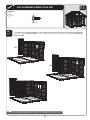
2.3
Repeat the previous step to connect all the Inner Floor Panels (AGJ) to each other. Finally, connect the last two Outer
Floor Panels (AGS & AGT) to the Inner Floor Panels.
AGJ
AGJ
AGJ
AGJ
AGS
AGT
30
SEC
TOOLS AND HARDWARE REQUIRED FOR THIS PAGE
2
NO HARDWARE REQUIRED FOR THIS PAGE
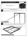
TWO PEOPLE REQUIRED FOR THIS STEP
SEC
2.4
!
SEC
2.5
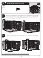
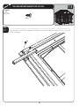
If you plan on anchoring your shed to your concrete platform, lay your Floor out on your platform in the
position you would like your shed to face. While another person holds the Floor in place, punch out one hole
by each seam and mark the position of that hole on the platform beneath.
Note: Pick only one hole by the seam.
Once all holes have been marked, remove the Floor from the platform and drill out the holes using a hammer drill
AND v MASONRY BIT /NCE ALL HOLES HAVE BEEN DRILLED POSITION THE &LOOR AGAIN ON THE PLATFORM BEING SURE TO
ALIGN THE HOLES IN THE &LOOR WITH THE HOLES YOU DRILLED IN THE PLATFORM 9OULL lNISH ANCHORING THE SHED AT THE END OF
the instructions. You’ll also find steps at the end of these instructions for anchoring your shed to a wood platform.
Holes are located here.
!
Note: Do not use a drill bit or hardware that exceeds 3/8” in diameter.
31
SEC
3
TRUSS & WALL CHANNEL ASSEMBLY
HARDWARE REQUIRED
Hardware shown at actual size
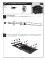
AAK (x10)
v X v (EX "OLT
Hardware shown at 50% of actual size
ADJ (x10)
1/4” Cap Nut
AHT X
Floor Bracket
AIP (x1)
4RUSS 'UTTER #ONNECTOR
METAL PARTS REQUIRED
Parts shown at 8% of actual size
71 11/16”
AFH (x8)
4RUSS 'UTTER #HANNEL
79 1/2”
AFG (x4)
Truss Brace Channel
79 1/2”
AFQ (x14)
Wall Support Channel
20 1/8”
AFP X
Truss Support Strip
PLASTIC PARTS REQUIRED
NO PLASTIC PARTS REQUIRED IN THIS SECTION
TOOLS REQUIRED
7/16” Wrench X
Safety Glasses
32
SEC
TOOLS AND HARDWARE REQUIRED FOR THIS PAGE
3
7/16” X
AAK (x6)
AIP (x1)
(Not to scale)
ADJ (x6)
SEC
3.1
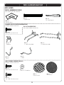
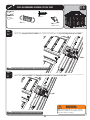
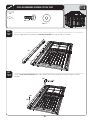
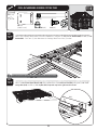
TRUSS ASSEMBLY
Fit two Truss Support Strips (AFP) together. Bolt Truss Support Strips, Truss Gutter Connector (AIP), and two Truss Gutter
Channels (AFH) as shown using the required hardware.
AIP
AFP
AAK
AFH
AFP
ADJ
AFH
AFP
AFP
WARNING
!
SEC
3.2
Do not overtighten the Cap Nut. If the end of
the Bolt breaks through the plastic cap, call our
Customer Service Department. Exposed threads
on the end of the Bolt may cause serious injuries.
Note: Only finger tighten hardware.
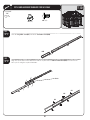
Attach Truss Support Strips (AFP) to the center of a Truss Brace Channel (AFG) (Truss Support Strips fit inside the Truss
Brace Channel). Attach each end of the Truss Brace Channel to the Truss Gutter Channels (AFH) using the required
hardware. Tighten all hardware.
AAK
AFP X
AFH
AFG
AFG
AAK
ADJ
ADJ
33
WARNING
Do not overtighten the Cap Nut.
SEC
TOOLS AND HARDWARE REQUIRED FOR THIS PAGE
3
7/16” X
AAK (x4)
AHT X
(Not to scale)
ADJ (x4)
SEC
3.3
Attach Truss Assembly to two Wall Support Channels (AFQ) using 1/4” x 1 1/2” Hex Bolts (AAK) and 1/4” Cap Nuts (ADJ).
Do not completely tighten the Cap Nut until after Truss is secured to the Wall.
AAK
AFH
AFQ
ADJ
AFQ
WARNING
!
SEC
3.4
Do not overtighten the Cap Nut.
Note: Only finger tighten hardware.
Attach one Floor Bracket (AHT) to the bottom of each Wall Support Channel and to the Floor. Tighten all hardware.
9OU NEED ONLY DO THIS STEP IF YOU PLAN TO ANCHOR YOUR 3HED 3EE THE h!NCHORING THE 3HEDv STEP AT THE END OF
your Owner’s Manual.
AFQ
ADJ
WARNING
AAK
Do not overtighten the Cap Nut.
AHT
REPEAT THIS SECTION FOR REMAINING TRUSSES
34
SEC
4
WALL PANEL INSTALLATION
HARDWARE REQUIRED
Hardware shown at actual size
ADZ (x78)
1/4” x 5/8” Pan-Head Screw
METAL PARTS REQUIRED
Part shown at 8% of actual size
77 1/2”
AFR X
Corner Channel
PLASTIC PARTS REQUIRED
Part shown at 4% of actual size
1000272
100XXXX
AHD (x10)
Wall Panel
AHH X
Window Wall Panel
TOOLS REQUIRED
Phillips Screwdriver
Safety Glasses
35
SEC
TOOLS AND HARDWARE REQUIRED FOR THIS PAGE
ADZ (x18)
SEC
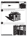
WALL ASSEMBLY
4.1
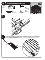
Lock a Wall Panel (AHD) into the right front corner position by inserting the tabs at the bottom of the Wall Panel
into the slots on the Shed Floor. After inserting the tabs, slide the Wall Panel to the right to lock it in place.
Install a Window Wall Panel (AHH) and secure with six (6) 1/4” x 5/8” Phillips Pan-Head Screws (ADZ).
AHD
AHH
SEC
4.2
Install two more Wall Panels (AHD) AND SECURE WITH TWELVE 1/4” x 5/8” Phillips Pan-Head Screws (ADZ).
AHD
AHD
!
Note: A second adult should apply pressure to the opposite side of the wall for easy insertion of screws.
36
4
SEC
TOOLS AND HARDWARE REQUIRED FOR THIS PAGE
ADZ X
SEC
4.3
Install next Wall Panel (AHD) at the right, rear corner of the Shed.
AHD
SEC
4.4
Align the holes in a Corner Channel (AFR) with the holes in two corner Wall Panels and secure the Corner Channel
TO THE 7ALL 0ANELS WITH TWELVE 1/4” x 5/8” Phillips Pan-Head Screws (ADZ).
AFR (x1)
77 1/2”
37
4
SEC
TOOLS AND HARDWARE REQUIRED FOR THIS PAGE
ADZ (x18)
SEC
4.5
Assemble next three Wall Panels (AHD). Secure the Wall Panels together with eighteen (18) 1/4” x 5/8” Phillips PanHead Screws (ADZ).
AHD
AHD
AHD
!
Note: A second adult should apply pressure to the opposite side of the wall for easy insertion of screws.
38
4
SEC
TOOLS AND HARDWARE REQUIRED FOR THIS PAGE
ADZ X
SEC
Install the next Wall Panel at the left, rear corner of the Shed and connect the two rear, corner Wall Panels (AHD)
WITH A #ORNER #HANNEL AND TWELVE 1/4” x 5/8” Phillips Pan-Head Screws (ADZ). Connect the next Wall Panel
using six (6) 1/4” x 5/8” Phillips Pan-Head Screws (ADZ).
4.6
AHD
AHD
SEC
4.7
Finally, install the last Window Wall Panel (AHH) and Wall Panel (AHD) TO THE 3HED USING TWELVE 1/4” x 5/8” Phillips
Pan-Head Screws (ADZ).
AHD
AHH
!
Note: A second adult should apply pressure to the opposite side of the wall for easy insertion of screws.
39
4
SEC
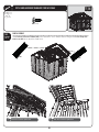
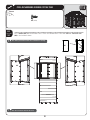
5 TRUSS FRAME & WALL SUPPORT INSTALLATION
HARDWARE REQUIRED
Hardware shown at actual size (*Unless otherwise noted)
ADZ (x96)
1/4” x 5/8” Pan-Head Screw
AAK (x18)
v X v (EX "OLT
(Not all are used)
ADJ (x18)
1/4” Cap Nut
(Not all are used)
AHT (x6)*
Floor Bracket
(Not used)
ACD (x4)
X v &LAT (EAD 3CREW
ADK (x4)
#AP .UT
METAL PARTS REQUIRED
Parts shown at 8% of actual size
16 1/2”
AFN X
Short Vertical Extension Channel
25 1/2”
AFJ X
Long Vertical Extension Channel
79 1/2”
AFQ (x4)
Wall Support Channel
PLASTIC PARTS REQUIRED
NONE PLASTIC PARTS REQUIRED FOR THIS SECTION
TOOLS REQUIRED
7/16” Wrench (x2)
7/16” Socket Wrench
Phillips Screwdriver
40
Safety Glasses
SEC
TOOLS AND HARDWARE REQUIRED FOR THIS PAGE
5
3/8” X
ADZ (x64)
ACD (x4)
ADK (x4)
SEC
TRUSS INSTALLATION
5.1
Starting at the back of the Shed, secure a Truss Frame Assembly to the center of each Left and Right Wall
Panel with the 1/4” x 5/8” Pan-Head Screws (ADZ). DO NOT use the 1/4” x 5/8” Pan-Head Screws (ADZ) to secure
the Truss Frame Assembly to the center divider in the Window Wall Panel.
SEC
3ECURE THE 4RUSS &RAME !SSEMBLY TO THE CENTER DIVIDER IN THE 7INDOW 7ALL 0ANEL WITH TWO #10 x 3/8” FlatHead Screws (ACD) through the holes in the center of the Window Wall Panels, and secure the Truss Frame
!SSEMBLY TO THE CENTER DIVIDER WITH TWO #10 Cap Nuts (ADK). Repeat this step for second Window Wall Panel.
100XXXX
5.2
!
Note: After installing Truss Assembly, tighten nuts completely.
41
WARNING
Do not overtighten the Cap Nut. If the end of
the Bolt breaks through the plastic cap, call our
Customer Service Department. Exposed threads
on the end of the Bolt may cause serious injuries.
SEC
TOOLS AND HARDWARE REQUIRED FOR THIS PAGE
7/16”
ADZ X
5
ADJ (x8)
AAK (x8)
SEC
5.3
REAR GABLE SUPPORT INSTALLATION
SEC
Attach a Long Vertical Extension Channel (AFJ) to a
Wall Support Channel (AFQ). Repeat.
Attach a Short Vertical Extension Channel (AFN) to
a Wall Support Channel. Ensure Extension
Channel is installed in the correct direction.
Repeat.
5.4
AFJ
AFN
ADJ
AAK
AFN
ADJ
ADJ
AFJ
AAK
ADJ
Use these holes to
Attach the Wall Support
Channel
AAK
AFQ
SEC
5.5
AFQ
3ECURE 7ALL 3UPPORTS TO REAR 7ALL USING THIRTY TWO 1/4” x 5/8” Phillips Pan-Head Screws (ADZ). Position the
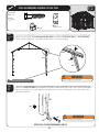
shorter Supports with Channels at the far left and far right Wall Panels. The long Supports are placed in the
MIDDLE POSITIONS $O NOT COMPLETELY TIGHTEN THE 3CREWS UNTIL AFTER THE REAR 'ABLE IS INSTALLED
AFJ
AFN
AFN
WARNING
Do not overtighten the Cap Nut.
!
AAK
Note: A second adult should apply pressure to the opposite side of the wall for easy insertion of screws.
42
SEC
6
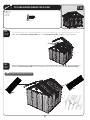
GABLE ASSEMBLY
HARDWARE REQUIRED
Hardware shown at actual size
AEE (x10)
X v &LAT 7ASHER
ADZ (x8)
1/4” x 5/8” Pan-Head Screw
ADW (x10)
X v 0AN (EAD 3CREW
METAL PARTS REQUIRED
NO METAL PARTS REQUIRED FOR THIS SECTION
PLASTIC PARTS REQUIRED
Parts shown at 4% of actual size
Parts shown at 15% of actual size
1000472
AGH X
'ABLE (ALF AGP X
Louvered Vent
1000470
AGI X
'ABLE (ALF AIQ X
Vent Screen
TOOLS REQUIRED
Phillips Screwdriver
Safety Glasses
43
SEC
TOOLS AND HARDWARE REQUIRED FOR THIS PAGE
ADZ (x8)
SEC
GABLE ASSEMBLY
6.1
Set the edge of Gable Half 2 (AGI) over the edge of Gable Half 1 (AGH) as shown.
AGI
AGH
SEC
6.2
3ECURE THE TWO 'ABLE (ALVES TOGETHER USING FOUR 1/4” x 5/8” Pan-Head Screws (ADZ).
ADZ
ADZ
ADZ
ADZ
44
6
SEC
TOOLS AND HARDWARE REQUIRED FOR THIS PAGE
6
ADW (x10)
AEE (x10)
SEC
6.3
Attach the Louvered Vent (AGP) and Vent Screen (AIQ) TO THE 'ABLE Assembly using five (5) #10 x 1/2” Flat Washers (AEE)
and five (5) #10 x 3/4” Phillips Pan-Head Screws (ADW) 3ET THE 'ABLE !SSEMBLY ASIDE UNTIL LATER Repeat this section for
the second Gable.
ADW
AEE
AIQ
AGP
45
SEC
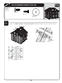
7 LEFT DOOR ASSEMBLY
HARDWARE REQUIRED
(ARDWARE SHOWN AT OF ACTUAL SIZE
Hardware shown at actual size
ABU X
v X v #ARRIAGE "OLT
AHM X
Dead Bolt Latch
ADJ X
1/4” Cap Nut
ADZ (x9)
1/4” x 5/8” Pan-Head Screw
AEB X
1/4” Flat Washer
METAL PARTS REQUIRED
Part shown at 8% of actual size
77 13/16”
BKZ (x1)
Center Hinge Assembly
26 1/4”
AFB X
Door Brace
PLASTIC PARTS REQUIRED
Part shown at 4% of actual size
AGO (x1)
Left Door
!
Note: The Left Door is slightly different from the other two; there are no holes for a handle.
TOOLS REQUIRED
Phillips Screwdriver
7/16” Wrench
Safety Glasses
46
SEC
TOOLS AND HARDWARE REQUIRED FOR THIS PAGE
ADZ (x9)
AHM (x1)
(Not to scale)
SEC
LEFT DOOR ASSEMBLY
7.1
7.1
3ECURE THREE Door Braces (AFB) to the inside of the Left Door (AGO) using the required hardware.
AFB
AFB
AFB
AGO
SEC
7.1
7.2
Place a Dead Bolt Latch (AHM) in the notch at the top of the door as shown. Orient a Center Hinge Assembly (BKZ) as
shown, and slide the Center Hinge Assembly down over the bottom lip of the Dead Bolt Latch and the end of
the Left Door.
BKZ
AHM
!
Note: Ensure the Center Hinge Assembly (BKZ) is oriented as shown. The hinge
goes toward the back of the door.
47
7
SEC
TOOLS AND HARDWARE REQUIRED FOR THIS PAGE
7/16”
ABU X
AHM (x1)
(Not to scale)
AEB X
ADJ X
SEC
7.1
7.3
Place a second Dead Bolt Latch (AHM) in the notch at the bottom of the Left Door, and continue sliding the Center
Hinge Assembly (BKZ) over the Left Door and over bottom lip of the second Dead Bolt Latch.
BKZ
!
AHM
Note: Ensure the Center Hinge Assembly (BKZ) is oriented as shown. The hinge
goes toward the back of the door.
SEC
7.1
7.4
Align the holes in the center of the Center Hinge Assembly with the notch in the edge of the Left Door. Secure
The Center Hinge Assembly to the Left Door using the required hardware.
ADJ
AEB
ABU
48
7
SEC
8
8
CENTER DOOR ASSEMBLY
HARDWARE REQUIRED
Hardware shown at actual size
Hardware shown at 15% of
actual size
AEE (x1)
X v &LAT 7ASHER
AHZ (x1)
Center Door Handle
ADZ (x9)
1/4” x 5/8” Pan-Head Screw
(ARDWARE SHOWN AT OF
actual size
ADW X
X v 0AN (EAD 3CREW
AIA (x1)
Center Door
Lock Bracket
BBH X
End Plug
BQP X
1/4” x 1 1/4” Carriage Bolt
AIB (x1)
AHM (x1)
Extended Strike Plate
Dead Bolt Latch
Hardware shown at 50% of
actual size
ADJ X
1/4” Cap Nut
BBI (x1)
Inside Center
Door Handle
ADX X
X v 0AN (EAD 3CREW
METAL PARTS REQUIRED
1 1/2”
Part shown at 8% of actual size
77 13/16”
BLH (x1)
Extended Door End Channel
BLG (x1)
Extended Door Brace
26 1/4”
AFB X
Door Brace
PLASTIC PARTS REQUIRED
Part shown at 4% of actual size
AGZ (x1)
Center Door
(The Center and Right Doors are the same part)
TOOLS REQUIRED
Phillips Screwdriver
7/16” Wrench
Safety Glasses
49
SEC
TOOLS AND HARDWARE REQUIRED FOR THIS PAGE
ADZ (x9)
BBH X
SEC
CENTER DOOR ASSEMBLY
7.1
8.1
Insert an End Plug (BBH) into each end of the Extended Door Brace (BLG), as shown.
BBH
BBH
BLG
SEC
7.1
8.2
3ECURE TWO Door Braces (AFB) and the Extended Door Brace (BLG) to the inside of the Center Door (AGZ), as shown,
using the required hardware.
ADZ
ADZ
ADZ
BLG
ADZ
ADZ
ADZ
ADZ
AFB
ADZ
ADZ
AFB
AGZ
50
8
SEC
TOOLS AND HARDWARE REQUIRED FOR THIS PAGE
AHZ (x1)
(Not to scale)
ADW X
BBI (x1)
(Not to scale)
ADW (x1)
(Not to scale)
AEE (x1)
SEC
Connect the Center Door Handle (AHZ) and the Inside Center Door Handle (BBI) to the Center Door using the hardware
shown.
7.1
8.3
ADW
BBI
ADW
AEE
AHZ
SEC
Orient the Extended Door End Channel (BLH), as shown, and slide the Channel down over the edge of the Center
Door. Insert a Dead Bolt Latch (AHM) into the notch at the bottom of the Center Door, as shown. Slide the
Extended Door End Channel over the Latch.
7.1
8.4
BLH
AFC
AHM
51
8
SEC
TOOLS AND HARDWARE REQUIRED FOR THIS PAGE
8
7/16”
AIB (x1)
(Not to scale)
ADJ X
BQP X
AIA (x1)
(Not to scale)
SEC
7.1
8.5
Orient the Extended Strike Plate (AIB) and slide it over the holes in the Extended Door End Channel, as shown.
AIB
SEC
7.1
8.6
Secure the Extended Strike Plate, Extended Door End Channel, and Center Door Lock Bracket (AIA) to the Center
Door using the required hardware.
ADJ
AIA
BQP
WARNING
Do not overtighten the Cap Nut. If the end of
the Bolt breaks through the plastic cap, call our
Customer Service Department. Exposed threads
on the end of the Bolt may cause serious injuries.
52
SEC
TOOLS AND HARDWARE REQUIRED FOR THIS PAGE
8
ADX X
SEC
7.1
8.7
Align the holes in the Extended Door Brace with those in the Extended Door End Channel, and secure using the
required hardware.
ADX
ADX
53
SEC
9 RIGHT DOOR ASSEMBLY
8
HARDWARE REQUIRED
Hardware shown at actual size
(ARDWARE SHOWN AT OF
actual size
AHV (x1)
Extended
Door Latch
ADJ X
1/4” Cap Nut
BQQ X
v X v #ARRIAGE "OLT
Hardware shown at 15% of
actual size
AEE X
X v &LAT 7ASHER
AIL (x1)
Right Door Lock
Bracket
AEB X
ADB X
1/4” Flat Washer v X v 3PACER
AIK (x1)
Right Door Handle
Hardware shown at 50% of
actual size
AHX (x1)
Latch Cover Plate
AHY (x1)
Latch Spring
AHW (x1)
Thumb Lever
Extension
ADW (x4)
X v 0HILLIPS 0AN (EAD 3CREW
AIO (x1)
ADZ (x9)
1/4” x 5/8” Phillips Pan-Head Screw
METAL PARTS REQUIRED
1 1/2”
Part shown at 8% of actual size
77 13/16”
BLH (x1)
Extended Door End Channel
AFB X
Door Brace
26 1/4”
PLASTIC PARTS REQUIRED
Part shown at 4% of actual size
AGZ (x1)
Right Door
(The Right and Center Doors are the same part)
TOOLS REQUIRED
#2 Phillips Screwdriver
7/16” Wrench
Needle-Nosed Pliers
54
Safety Glasses
SEC
TOOLS AND HARDWARE REQUIRED FOR THIS PAGE
9
ADZ (x9)
SEC
RIGHT DOOR ASSEMBLY
9.1
3ECURE THREE Door Braces (AFB) to the inside of the Right Door (AGZ) using the required hardware.
AFB
AFB
AFB
AGZ
SEC
9.2
Slide a Extended Door End Channel (BLH) down over the edge of the Right Door as shown.
BLH
BLH
55
AHZ (x1)
(Not to scale)
SEC
TOOLS AND HARDWARE REQUIRED FOR THIS PAGE
ADW X
AIO (x1)
(Not to scale)
AEE X
SEC
9.3
Slide the nubs of the Thumb Lever (AIO) down the slots and into the holes of the Right Door Handle (AIK).
Hole
AIO
Nub
Slots
AIK
SEC
9.4
Insert the end of the Thumb Lever through the slot in the Right Door and connect the Door Handle Assembly to
the Right Door using the hardware shown.
ADW
AEE
ADW
AEE
AIK
56
9
SEC
TOOLS AND HARDWARE REQUIRED FOR THIS PAGE
7/16”
ADJ X
AEB X
AHV (x1)
(Not to scale)
BQQ X
AIL (x1)
(Not to scale)
AHX (x1)
(Not to scale)
ADB X
SEC
9.5
Align the holes in the center of the Extended Door End Channel with the notch in the edge of the Right Door.
Connect the Right Door Lock Bracket (AIL), Extended Door Latch (AHV), and Latch Cover Plate (AHX) to the Right Door as
shown using the required hardware.
ADJ
ADJ
AHX
9.5
AHV
ADB
AEB
ADB
AEB
AIL
BQQ
BQQ
57
9
SEC
TOOLS AND HARDWARE REQUIRED FOR THIS PAGE
9
ADW (x1)
AHY (x1)
AHW (x1)
(Not to scale)
SEC
9.6
7.1
Connect the Thumb Lever Extension (AHW) to the Thumb Lever with one (1) #10 x 3/4” Phillips Pan-Head Screw (ADW).
ADW
AHW
!
Note: The lip of the Thumb Lever Extension (AHW) fits under the Thumb Lever .
SEC
7.1
9.7
Connect the Latch Spring (AHY) to the Extended Door Latch (AHV) and Latch Cover Plate (AHX).
AHV
AHX
AHY
WARNING
!
While performing this step, each person
should use protective eye glasses to help
prevent serious eye injury.
Note: Use pliers to pull spring down and hook into bottom hole.
58
SEC
10
DOOR FRAME AND DOOR INSTALLATION
HARDWARE REQUIRED
Hardware shown at actual size
BBL (x6)
ADZ X
v X v (EX "OLT
1/4” x 5/8” Pan-Head Screw
BBM (x4)
ABU (x6)
v X v 4HREAD #UTTING 3CREW v X v #ARRIAGE "OLT
AAU (x4)
1/4” Cap Nut
BBG (x1)
v X v (EX "OLT
AAV X
5/16” Jam Nut
ACA (x4)
v X v #ARRIAGE "OLT
0ART SHOWN AT OF ACTUAL SIZE
BBN (x1)
Carriage Latch
AEB (x8)
1/4” Flat Washer
ADJ X
1/4” Cap Nut
Parts shown at 50% of actual size
AHL X
Dead Bolt Strike Plate
BBE X
Carriage Wheel
BBK (x1)
Carriage Bracket
CJR X
Door Frame Support Bracket
BBJ (x1)
4” Floor Strike Plate
METAL PARTS REQUIRED
Parts shown at 8% of actual size
78 1/4”
BLJ X
Corner Door Frame
Top
BMG (x1)
Right Hinge Assembly
Bottom
78 1/4”
59
METAL PARTS REQUIRED
Parts shown at 8% of actual size
Top
Bottom
78 1/4”
BLK (x1)
Left Hinge Assembly
69 1/4”
BLL (x1)
,ONG 'LIDER 4RACK
13”
BLM (x1)
3HORT 'LIDER 4RACK
57”
BLN (x1)
'LIDER 4RACK %XTENSION
Part shown at 15% of actual size
BLI X
Corner Frame Bracket
TOOLS REQUIRED
Phillips Screwdriver
AID (x1) (Not to scale)
Safety Glasses
60
SEC
TOOLS AND HARDWARE REQUIRED FOR THIS PAGE
10
NO HARDWARE REQUIRED FOR THIS PAGE
SEC
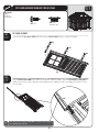
10.1
7.1
Ensure you use the correct Hinge Assembly for the Left and Right Doors. The hinge faces outward on each
door, and the head of the hinge pin always goes on top.
Hinge faces outward and head
of hinge pin goes on top.
Hinge faces outward and head
of hinge pin goes on top.
Use these holes when
connecting the Left and
Right Doors to the Hinge
Assemblies.
Left Door Hinge
Right Door Hinge
61
SEC
TOOLS AND HARDWARE REQUIRED FOR THIS PAGE
NO HARDWARE REQUIRED FOR THIS PAGE
SEC
LEFT DOOR ASSEMBLY
10.2
7.1
Slide the Left Door Assembly down through the channel of a Left Hinge Assembly (BLK) as shown.
Rear side of Left Door
BLK
BLJ
62
10
SEC
TOOLS AND HARDWARE REQUIRED FOR THIS PAGE
10
7/16”
ABU X
ADJ X
AEB X
SEC
10.3
7.1
Align the holes in the Left Hinge Assembly with the notch in the Left Door, and secure the Left Hinge Assembly
to the Left Door using the required hardware.
ADJ
AEB
ABU
SEC
10.4
7.1
Slide a Corner Door Frame (BLJ) into the Left Hinge Assembly, and align the holes, as shown.
BLJ
63
SEC
TOOLS AND HARDWARE REQUIRED FOR THIS PAGE
7/16”
BBL X
AEB (x1)
SEC
10.5
7.1
7.4
Secure a Corner Frame Bracket (BLI) to the Corner Door Frame and Left Hinge Assembly using the required
hardware.
BBL
BLI
BBL
AEB
SEC
CENTER DOOR ASSEMBLY
10.6
7.1
7.4
Slide the Center Door Assembly down through the channel of the Door Hinge End Channel, as shown.
64
10
SEC
TOOLS AND HARDWARE REQUIRED FOR THIS PAGE
10
7/16”
ABU X
ADJ X
AEB X
SEC
RIGHT DOOR ASSEMBLY
10.7
7.1
Orient the Right Hinge Assembly (BMG), as shown. Slide the Hinge Frame down over the right side of the Right Door
(AGZ), as shown.
BMG
BMG
AGZ
Rear side of Right Door
SEC
10.8
7.1
Align the holes in the Right Hinge Assembly with the notch in the Right Door, and secure the Right Hinge
Assembly to the Right Door using the required hardware.
ADJ
AEB
ABU
65
7/16”
BBL X
AEB (x1)
SEC
8.1
10.9
7.1
Slide the Right Hinge Assembly over a Corner Door Frame (BLJ) and align the holes, as shown.
BLJ
SEC
8.1
10.10
7.1
Secure a Corner Frame Bracket (BLI) to the Corner Door Frame and Right Hinge Assembly using the required
hardware.
BBL
BLI
BBL
AEB
66
SEC
TOOLS AND HARDWARE REQUIRED FOR THIS PAGE
10
SEC
TOOLS AND HARDWARE REQUIRED FOR THIS PAGE
7/16”
ADJ (x4)
ACA (x4)
SEC
10.11
7.1
Slide the Long Glider Track (BLL) next to the Short Glider Track (BLM).
BLL
BLM
SEC
10.12
7.1
Align the square holes in the two Tracks with the square holes in Glider Track Extension (BLN) and connect the
three pieces using the required hardware.
Notch
ADJ
BLN
ADJ
ADJ
ACA
ACA
ACA
67
10
SEC
TOOLS AND HARDWARE REQUIRED FOR THIS PAGE
10
7/16”
BBM (x4)
SEC
8.4
8.1
10.13
7.1
SEC
8.4
8.1
10.14
7.1
0LACE THE 'LIDER 4RACK !SSEMBLY ON THE #ORNER &RAME "RACKETS AS SHOWN 4HE ,ONG AND 3HORT 'LIDER 4RACKS GO
over the Left and Center Doors.
Connect the right side of the Top Door Frame Assembly to the right Corner Bracket using the required
hardware. Connect the left side of the Top Door Frame Assembly and the Carriage Latch (BBN) to the left Corner
Frame Bracket using the required hardware.
BBM
BBM
BBM
BBN
BBM
68
SEC
TOOLS AND HARDWARE REQUIRED FOR THIS PAGE
10
7/16”
AID (x1)
(Not to scale)
BBF X
BBE X
(Not to scale)
ADJ X
SEC
8.1
8.4
10.15
7.1
Connect both Carriage Wheels (BBE) to the Carriage Bracket (BBK) to form the Carriage Assembly using the required
hardware. Do not overtighten.
BBE
ADJ
ADJ
BBF
BBE
BBK
SEC
8.1
8.4
10.16
7.1
Place the Carriage Wheels into the Header Frame Track Assembly.
69
BBF
SEC
TOOLS AND HARDWARE REQUIRED FOR THIS PAGE
10
5/16” X
BBG (x1)
CJR X
(Not to scale)
SEC
8.4
8.1
10.17
7.1
AAU (x4)
ACA (x4)
AAV X
Connect the Carriage Bracket to the Extended Door Brace using one (1) 5/16” x 2 1/2” Hex Bolt (BBG) AND TWO 5/16”
Jam Nuts (AAV). Place one (1) Jam Nut above the Carriage Bracket and one (1) below.
AAV
BBG
!
SEC
8.4
8.1
10.18
7.1
Note: You may need to adjust the Nuts (AAV) later on to allow the door to open freely.
Connect a Door Frame Support Bracket (CJR) to the bottom of the left Corner Door Frame (BLJ) USING TWO 1/4” x 1/2”
Carriage Bolts (ACA) AND TWO 1/4” Cap Nuts (AAU). Repeat this step for the right Corner Door Frame.
BLJ
ACA
AAU
CJR
70
SEC
TOOLS AND HARDWARE REQUIRED FOR THIS PAGE
10
ADZ (x5)
SEC
8.4
8.1
10.19
7.1
SEC
8.4
8.1
10.20
7.1
!
AT LEAST TWO ADULTS REQUIRED FOR STEPS ON THIS PAGE
Place the bottom of the Door/Frame Assembly next to the front Floor Panels of the shed, and lift the Door/
Frame Assembly up in place.
4HERE ARE TWO COLUMNS OF HOLES ALONG THE #ORNER &RAMES !LIGN THE COLUMN OF lVE HOLES #OLUMN IN THE
right Corner Frame with those near the end of the Wall Panel. While at least one adult holds the Door/Frame
Assembly in place, connect the right Corner Frame to the Wall Panel using five (5) 1/4” x 5/8” Pan-Head Screws
(ADZ).
Col Column
mn
1
ColumnCol2mn 2
Note: Use the second column of holes in from the Right Door.
71
SEC
TOOLS AND HARDWARE REQUIRED FOR THIS PAGE
10
7/16”
ABU X
ADJ X
ADZ (x6)
SEC
8.4
8.1
10.21
7.1
AEB X
AT LEAST TWO ADULTS REQUIRED FOR THIS STEP
There are two columns of holes along the Corner Frames. Align the column of six (6) holes (Column 1) in the
left Corner Frame with those near the end of the Wall Panel. While at least one adult holds the Door/Frame
Assembly in place, connect the left Corner Frame to the Wall Panel using six (6) 1/4” x 5/8” Pan-Head Screws (ADZ).
ColumnColumn
11
!
SEC
8.4
8.1
10.22
7.1
Column 2
Column 2
Note: Use the first column of holes in from the Left Door.
Align the holes in the Door Hinge End Channel with the notch in the Center Door and secure the Center Door to
the Hinge using the required hardware.
ABU AEB
ADJ
72
SEC
TOOLS AND HARDWARE REQUIRED FOR THIS PAGE
ADX (x4)
AHL X
BBJ (x1)
ADZ X
SEC
8.1
8.4
10.23
7.1
0LACE THE TWO Dead Bolt Strike Plates (AHL) in the indentations on the Floor Panels at the locations shown.
/RIENT THE &LOOR 3TRIKE 0LATES SO THE HOLES MATCH THOSE IN THE &LOOR 0ANELS AND SECURE WITH TWO #10 x 1/2”
Pan-Head Screws (ADX). Finally, secure the 4” Floor Strike Plate (BBJ) AT THE LOCATION SHOWN USING TWO 1/4” x 5/8”
Pan-Head Screws (ADZ).
ADX
ADX
ADZ
AHL
AHL
BBJ
73
10
SEC
11 CORNER TRIM INSTALLATION
HARDWARE REQUIRED
Hardware shown at actual size
ACK (x4)
X v 0AN (EAD 3CREW
ADX X
X v 0AN (EAD 3CREW
(ARDWARE SHOWN AT OF ACTUAL SIZE
AGA X
Black, Plastic Corner Trim Bracket
BMH (x10)
Metal Corner Trim Bracket
METAL PARTS REQUIRED
NO METAL PARTS REQUIRED FOR THIS SECTION
PLASTIC PARTS REQUIRED
Part shown at 8% of actual size
78 13/16”
AQX (x4)
Corner Trim
TOOLS REQUIRED
Phillips Screwdriver
Safety Glasses
74
SEC
TOOLS AND HARDWARE REQUIRED FOR THIS PAGE
ADX (x10)
SEC
FRONT CORNER TRIM INSTALLATION
11.1
11.1
Using the required hardware, connect five (5) Metal Corner Trim Brackets (BMH) to the front corners of your Shed,
as shown.
BMH
ADX
BMH
ADX
11.2
SEC
11.2
11.1
Slide a Corner Trim (AQX) over the Metal Corner Trim Brackets, as shown.
AQX
75
11
SEC
TOOLS AND HARDWARE REQUIRED FOR THIS PAGE
ACK X
SEC
11.3
Align the top of the Corner Trim with the top of the Wall Wall Panel and fasten with a #8 x 1” Phillips Pan-Head
Screw (ACK). Insert the Screw on the side of the Shed to hide it under the eaves. Repeat steps 11.1 - 11.3 for the
second Front Corner Trim.
ACK
76
11
SEC
TOOLS AND HARDWARE REQUIRED FOR THIS PAGE
ADX X
11
ACK X
SEC
REAR CORNER TRIM INSTALLATION
11.4
11.4
11.1
Snap six (6) Plastic Corner Trim Brackets (AGA) TO A REAR CORNER OF THE 3HED &ASTEN EACH "RACKET WITH TWO #10 x
1/2” Phillips Pan-Head Screws (ADX).
ADX
AGA
ADX
!
Note: The tab on the Trim Brackets fit into the six screw indentations along each corner of the Shed.
11.2
SEC
11.5
11.5
11.1
Slide a Corner Trim (AQX) onto the Plastic Corner Trim Brackets.
Align the top of the Corner Trim with the top of the Wall Panel and
fasten with a #8 Phillips Pan-Head Screw (ACK). Insert the Screw on
the side of the Shed to hide it under the eaves. Repeat steps 11.4 11.5 for the second Rear Corner Trim.
ACK
AQX
AQX
WARNING
Use extreme caution when standing on ladders to
perform assembly steps. Follow all warnings and
cautions on the ladder. Failure to follow all of these
instructions and warnings could lead to serious
personal injury or property damage.
77
SEC
12
DOMED SKYLIGHT ASSEMBLY
HARDWARE REQUIRED
Hardware shown at actual size (*Unless noted otherwise)
ACR X
X v #ARRIAGE "OLT
AEE X v &LAT 7ASHER
ADK #AP .UT
*AHI X
Butyl Tape
METAL PARTS REQUIRED
NO METAL PARTS REQUIRED FOR THIS SECTION
PLASTIC PARTS REQUIRED
Part shown at 8% of actual size
Part shown at 4% of actual size
AGB X
Domed Skylight
1015533
AHB X
Roof Panel for Domed Skylight
TOOLS REQUIRED
Phillips Screwdriver
3/8” Wrench
Safety Glasses
78
SEC
TOOLS AND HARDWARE REQUIRED FOR THIS PAGE
12
AHI X
(Not to scale)
SEC
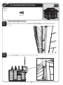
DOMED SKYLIGHT ASSEMBLY
12.1
Use a plain screwdriver to gently remove any excess plastic from the twelve holes in the Roof Panel for Domed
Skylight (AHB). It’s important that the hole stay square; try not to round the corners of the edges of the holes. Stick the end
of the Butyl Tape (AHI) over the groove and top, left hole of the Roof Panel for Domed Skylight as indicated below.
Move to the right and over the groove covering all the holes along the top of the opening. Once the top, right
corner and hole are covered, cut the Butyl Tape. Run your finger along the paper backing pressing down
slightly to remove any gaps or bubbles between the Butyl Tape and the groove. Remove the paper backing from
the piece of Butyl Tape you just applied. Overlap the end of the roll of Butyl Tape with the end you just cut and
apply the Butyl Tape over the holes along the groove on the right of the opening. Continue applying the Butyl
Tape in this fashion until all holes have been covered and the ends overlap.
Top
AHB
Groove along grayed area
Exterior View
!
Note: Use a screwdriver to remove any excess plastic from all
holes in Panel.
!
Note: Butyl Tape must cover all twelve holes.
12.2
SEC
Remove the protective plastic film from both sides of the Domed Skylight (AGB). Carefully align the holes in the
Domed Skylight with those in the Butyl Tape. Set the Domed Skylight over the opening in the Roof Panel for
Domed Skylight. Press down and verify there are no gaps or bubbles between the Butyl Tape and the Domed
Skylight.
Top
AGB
AGB X
Exterior View
79
SEC
TOOLS AND HARDWARE REQUIRED FOR THIS PAGE
12
3/8”
ADK X
AEE X
ACR X
SEC
12.3
Insert one (1) #10 x 5/8” Carriage Bolt (ACR) through each hole in the Domed Skylight. Press the Bolt through the
Butyl Tape and through the Roof Panel for Domed Skylight.
ACR
ACR
ACR
Exterior View
SEC
12.4
Secure the Domed Skylight to the Roof Panel with one (1) #10 Flat Washer (AEE) and one (1) #10 Cap Nut (ADK) for
each Carriage Bolt. Set Skylight/Panel Assembly aside.
ADK
AEE
AEE
ADK
WARNING
Do not overtighten the Cap Nut. If the end of
the Bolt breaks through the plastic cap, call our
Customer Service Department. Exposed threads
on the end of the Bolt may cause serious injuries.
Interior View
80
SEC
13 GABLE INSTALLATION
HARDWARE REQUIRED
Hardware shown at actual size
ADZ X
1/4” x 5/8” Phillips Pan-Head Screw
METAL PARTS REQUIRED
NO METAL PARTS REQUIRED FOR THIS SECTION
PLASTIC PARTS REQUIRED
Parts shown at 4% of actual size
1000470
1000472
&RONT 'ABLE !SSEMBLY
(Assembled earlier)
1000472
1000470
2EAR 'ABLE !SSEMBLY
(Assembled earlier)
TOOLS REQUIRED
Phillips Screwdriver
Safety Glasses
81
SEC
TOOLS AND HARDWARE REQUIRED FOR THIS PAGE
13
ADZ X
SEC
13.1
!
REAR GABLE INSTALLATION
3ECURE THE 2EAR 'ABLE TO THE REAR 7ALL AND 6ERTICAL %XTENSION #HANNELS USING TWENTY TWO 1/4” x 5/8” Phillips
Pan-Head Screws (ADZ).
Note: Tighten the Screws on the Vertical Extension Channels after the Gable is installed.
FRONT GABLE INSTALLATION
SEC
13.2
3ECURE THE &RONT 'ABLE TO THE TOP OF THE $OOR &RAME AS SHOWN AND SECURE WITH FOUR 1/4” x 5/8” Phillips Pan-Head
Screws (ADZ) at the locations shown.
Secure Front Gable to the top of the door frame at these locations.
82
SEC
14
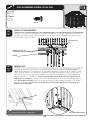
GABLE BRACE & ROOF INSTALLATION
HARDWARE REQUIRED
Hardware shown at actual size (*Unless otherwise noted)
AED X X v &ENDER 7ASHER
ADZ (x185) 1/4” x 5/8” Pan-Head Screw
(Not all are used)
ACJ X X v 0AN (EAD 3CREW
ADX (4)
X v 0AN (EAD 3CREW
AJA &OAM #UBE
ACF X X v 0AN (EAD 3CREW
METAL PARTS REQUIRED
14 7/16”
Parts shown at 8% of actual size
AFF X
'ABLE 4RUSS "RACE
10”
28 7/8”
AFL X 2OOF 3UPPORT 3TRIP
PLASTIC PARTS REQUIRED
Parts shown at 4% of actual size (*Unless otherwise noted)
1000541
1003372
AGU X /UTER 2OOF 0ANEL !
AGV X /UTER 2OOF 0ANEL "
1000476
1015533
AGQ X #ENTER 2OOF 0ANEL
AHB X 2OOF 0ANEL FOR $OMED 3KYLIGHT
AFY X
#ENTER 2OOF #AP
1021070
AGE X
%ND 2OOF #AP
TOOLS REQUIRED
Phillips Screwdriver
Safety Glasses
83
ADK (x1)
#AP .UT
AHA X
2OOF #AP #OVER
SEC
TOOLS AND HARDWARE REQUIRED FOR THIS PAGE
SEC
14.1
ADK (x1)
ACF (x1)
ADX (x4)
GABLE BRACE INSTALLATION
Install the Gable Truss Brace (AFF) BETWEEN THE END 4RUSS AND THE 2EAR 'ABLE 9OU WILL NEED TO REMOVE THE 1/4” x 1
1/2” Hex Bolts (AAK) and the 1/4” NKE Cap Nuts (ADJ) from the bottom of the Truss Assembly, and then reattach to the
'ABLE 4RUSS "RACE #ONNECT THE "RACE DIRECTLY TO THE 'ABLE WITH TWO #10 x 1/2” Pan-Head Screws (ADX). Repeat
THIS STEP FOR THE &RONT 'ABLE CONNECTING THE 'ABLE "RACE TO THE CENTER OF THE TOP OF THE $OOR (EADER #HANNEL
with one (1) #10 x 5/16” Pan-Head Screw (ACF) and one (1) #10 Cap Nut (ADK) 9OU MAY NEED TO SLIGHTLY ADJUST THE
'ABLE 4RUSS "RACE
AAK
ADX
ADJ
AFF
Rear Gable
AFF
ADK
ACF
WARNING
Front Gable
!
14
Do not overtighten the Cap Nut.
Note: There are no pilot holes in the Gable to receive the Screws (ADX). Insert them directly into the plastic.
84
SEC
TOOLS AND HARDWARE REQUIRED FOR THIS PAGE
14
ADZ X
ROOF ASSEMBLY
14.2
Install Outer Roof Panels A & B (AGU & AGV) at the front of the Shed. Always start inserting the 1/4” x 5/8” Phillips PanHead Screws (ADZ) at the top of the Roof Panel.
10
03
37
2
SEC
AGV
AGU
41
5
00
10
ADZ
ADZ
!
Note: This is an interior upward view.
!
85
Note: This is an interior upward view.
SEC
TOOLS AND HARDWARE REQUIRED FOR THIS PAGE
14
ADZ X
SEC
14.3
)NSTALL TWO Inner Roof Panels (AGQ) and four (4) Roof Support Strips (AFL) to the Shed as shown. Roof Panels for
Skylights (AHB) can be inserted into any of the center Roof Panel sections.
AFL
!
Note: This section applies to the two types of Roof Panels: Inner Roof Panel (AGQ) and Roof Panel for Domed Skylight (AHB).
Fit three Roof Support Strips (AFL) (dark gray) into the slots (light gray) in the Center Roof Panels and Roof Panels for Domed
Skylight as you put them in place.
AGQ or AHB
ADZ
ADZ
AFL
28 7/8”
!
Note: The holes in the Roof Support Strips are for manufacturing purposes only.
86
AFL (x4)
SEC
TOOLS AND HARDWARE REQUIRED FOR THIS PAGE
ADZ X
SEC
!TTACH TWO Roof Panels for Skylights (AHB) and six (6) Roof Support Strips (AFL) using the required hardware.
14.4
AFL
SEC
Position the Outer Roof Panel A (AGU) AND SECURE TO 'ABLE 2EPEAT ON THE OTHER SIDE WITH Outer Roof Panel B (AGV).
14.5
Note: Only use a hand screwdriver on this step.
1
054
03
37
2
100
10
!
AGV
87
AGU
14
SEC
TOOLS AND HARDWARE REQUIRED FOR THIS PAGE
ADZ X
ACJ X
AED X
SEC
14.6
Connect the End Roof Caps (AGE) and Center Roof Caps (AFY) TO THE 2OOF AND 'ABLES USING THE REQUIRED HARDWARE
AFY
AGE
AFY
AFY
AGE
ADZ
ACJ
ACJ
AED
AED
ACJ
AED
ACJ
AED
88
14
SEC
TOOLS AND HARDWARE REQUIRED FOR THIS PAGE
AJA X
14
ADZ X
SEC
Install a Roof Cap Cover (AHA) AT THE FRONT AND REAR OF THE 3HED USING TWO 1/4” x 5/8” Phillips Pan-Head Screws (ADZ)
for each Roof Cap Cover.
14.7
AHA
AHA
ADZ
ADZ
SEC
Along the outside edges of the Shed, fasten the Channels to the underside of the Roof Panels (Fig. 1). Insert
two Foam Cubes (AJA) AT EACH #HANNEL LOCATION &IG 14.8
Fig. 1
ADZ
ADZ
ADZ
AJA
AJA
Fig. 2
AJA
!
CAUTION
Note: Snow Load Kits are available from Customer Service for high snow
areas (see back cover).
If more than six (6) inches of snow accumulate
on the roof of the shed, carefully remove the
snow to avoid possible roof collapse. While
standing on the ground, remove the snow from
the roof with a broom or snow shovel. Do not
stand on the roof to remove snow.
89
SEC
15 WINDOW ASSEMBLY & INSTALLATION
HARDWARE REQUIRED
Hardware shown at actual size
ADX (x44)
X v 0AN (EAD 3CREW
ADZ (x8)
1/4” x 5/8” Pan-Head Screw
ADW (x8)
X v 0AN (EAD 3CREW
ACB (x8)
X v 0AN (EAD 3CREW
ACF (x4)
X v 0AN (EAD 3CREW
ACD (x4)
X v &LAT (EAD 3CREW
AEE (x4)
X v &LAT 7ASHER
ADK (x4)
#AP .UT
(ARDWARE SHOWN AT OF ACTUAL SIZE
AIE (x4)
Mounted Window Stay
AIN (x4)
Sliding Window Stay
AIV (x4)
Window Stay Bracket
Hardware shown at 50% of actual size
AIU (x8)
Window Latch Bearing
AIT (x8)
Window Latch
METAL PARTS REQUIRED
NO METAL PARTS REQUIRED FOR THIS SECTION
PLASTIC PARTS REQUIRED
Parts shown at 8% of actual size
1004595
AHG (x4)
Window Frame
AHF (x4)
Window
TOOLS REQUIRED
Phillips Screwdriver
Safety Glasses
90
AIR (x8)
Window Hinge Tube
SEC
TOOLS AND HARDWARE REQUIRED FOR THIS PAGE
AIR (x4)
(Not to scale)
SEC
15.1
Slide Window Hinge Tubes (AIR) into the upper and lower hinge holes and fit a Window Frame (AHG) over the Hinge
Tubes.
AHH
AHG
AIR
AIR
AIR
AIR
91
AHG
15
SEC
TOOLS AND HARDWARE REQUIRED FOR THIS PAGE
ADX X
SEC
15.2
1004595
!
Place a Window (AHF) onto the Window Frame. Fasten the Window to the Frame with #10 x 1/2” Pan Head Screws
(ADX) in the locations shown.
Note: Remove plastic film from both sides of window before installing.
AHF
AHG
AHF
!
AHF
Note: Insert Screws into the holes with circles.
92
15
SEC
TOOLS AND HARDWARE REQUIRED FOR THIS PAGE
AIE X
(Not to scale)
AIV X
(Not to scale)
15
ADZ (x4)
ADW (x4)
SEC
Attach Window Stay Brackets (AIV) to the inside of the Window Wall Panel (AHH).
15.3
AIV
AIV
ADZ
ADZ
ADZ
ADZ
AHH
SEC
Window
Hinged Side
Attach a Mounted Window Stay (AIE) to the bottom of the Window Frame.
Hinged Side
15.4
Window
AIE
AIE
ADW
ADW
ADW
93
ADW
SEC
TOOLS AND HARDWARE REQUIRED FOR THIS PAGE
ADX X
AEE X
AIN X
(Not to scale)
ACF X
SEC
Fit a Sliding Window Stay (AIN) into the Mounted Window Stay. To add rigidity to the nub of the Sliding Window
Stays, insert #10 x 1/2” Pan-Head Screws (ADX) as shown.
15.5
AIN
AIE
AIE
AIN
ADX
SEC
15.6
Attach a Sliding Window Stay (AIN) to the Window Stay Bracket (AIV) using the required hardware.
AIN
AIN
AIV
AIV
AEE
ACF
AEE
ACF
94
15
SEC
TOOLS AND HARDWARE REQUIRED FOR THIS PAGE
15
ACB (x4)
AIT (x4)
(Not to scale)
AIU (x4)
(Not to scale)
SEC
15.7
!
Fit a Window Latch Bearing (AIU) into a Window Latch (AIT). Attach the Window Latch to the upper latch location with a
#10 x 1 1/4” Pan-Head Screw (ACB). Repeat for other Window Latches.
Note: Ensure notch in Window Latch Bearing fits over the plastic ridge in the Window Frame.
AIT
AIT
Notch
AIU
ACB
Ridge
REPEAT THIS SECTION FOR THE SECOND WINDOW WALL PANEL AND WINDOW.
95
ACB
AIU
SEC
16 DOOR WINDOW INSTALLATION
HARDWARE REQUIRED
Hardware shown at actual size
ADZ X
1/4” x 5/8” Pan-Head Screw
METAL PARTS REQUIRED
NO METAL PARTS REQUIRED FOR THIS SECTION
PLASTIC PARTS REQUIRED
Parts shown at 4% of actual size
BLO X
Door Window
TOOLS REQUIRED
Phillips Screwdriver
Safety Glasses
96
ADZ X
SEC
DOOR WINDOW INSTALLATION
16.1
Connect a Door Window (BLO) to each Door using the required hardware.
97
SEC
TOOLS AND HARDWARE REQUIRED FOR THIS PAGE
16
SEC
SEC
17
ACCESSORY INSTALLATION
HARDWARE REQUIRED
Hardware shown at actual size
ADW (x10)
X v 0AN (EAD 3CREW
ADX (x8)
X v 0AN (EAD 3CREW
AIG (x1)
4” Double-Arm Hook
Hardware shown at 50% of actual size
AIJ X
Toolholder
AII X
L-Hook
AIF X v
Double-Arm Hook
AIH X
J-Hook
METAL PARTS REQUIRED
Hardware shown at actual size
AIZ (x4)
Shelf Support for 14” Shelf
PLASTIC PARTS REQUIRED
Part shown at 4% of actual size
Part shown at 15% of actual size
1002315
AFT X
v X v 3HELF
AFU (x1)
Pegboard Strip
TOOLS REQUIRED
Phillips Screwdriver
7/16” Wrench
Safety Glasses
98
15
SEC
TOOLS AND HARDWARE REQUIRED FOR THIS PAGE
ADX (x8)
AEE (x8)
SEC
14” x 30” SHELF INSTALLATION
17.1
Insert Shelf Brackets (AIZ) into notches in any Wall Support Channel. Place a 14” x 30” Shelf (AFT) on the Shelf
Brackets and secure with #10 Flat Washers (AEE) and #10 x 1/2” Pan-Head Screws (ADX). Repeat this step for the second
Shelf.
AFT
AEE
AIZ
ADX
!
17.2
99
Note: There are no pilot holes on the bottom of the shelf;
screws are inserted directly into the plastic.
17
SEC
TOOLS AND HARDWARE REQUIRED FOR THIS PAGE
17
ADW (x10)
(Not all screws are used)
SEC
PEGBOARD STRIP INSTALLATION
17.3
Using a Level, position the Pegboard Strip (AFU) in the desired location. Screw the Pegboard Strip to the Wall
using five (5) #10 x 3/4” Phillips Pan-Head Screws (ADW). See Note.
!
Note: The Pegboard Strip is screwed directly into the plastic. Line up the Strip anywhere on Wall so holes are over plastic (and not over a groove in
the Wall).
AFU
ADZ (x4)
ADW
!
Note: Ensure the Pegboard Strip is level before inserting Screws.
SEC
17.4
Insert Hooks (AIF, AIG, AIH, AII, and AIJ).
100
SEC
18
FINAL STEPS
HARDWARE REQUIRED
Hardware shown at actual size
ADZ (x4)
1/4” x 5/8” Pan-Head Screw
CHECK WITH YOUR LOCAL HARDWARE STORE FOR ANCHORING HARDWARE FOR YOUR PLATFORM
METAL PARTS REQUIRED
NO METAL PARTS REQUIRED FOR THIS SECTION
PLASTIC PARTS REQUIRED
NO PLASTIC PARTS REQUIRED FOR THIS SECTION
TOOLS REQUIRED
5/16” Wrench X
Phillips Screwdriver
Hammer Drill
101
Safety Glasses
SEC
TOOLS AND HARDWARE REQUIRED FOR THIS PAGE
18
5/16” X
ADZ (x4)
SEC
CENTER & LEFT DOOR ADJUSTMENT
18.1
18.1
9OU MAY NEED TO ADJUST THE HEIGHT OF THE #ENTER $OOR TO ELIMINATE AN UNEVEN GAP ,OOSEN THE TWO .UTS ON THE
Hex Bolt on the Carriage Bracket to raise or lower the Center Door. Once the door has been adjusted to the
desired height, retighten the Nuts.
Carriage Bracket
Adjust these nuts to raise
and lower the Center Door.
Hex Bolt
SEC
ANCHORING SHED
18.2
18.1
If you plan on anchoring your shed, you can anchor it to your platform through the Floor Brackets (AHT) at the
bottom of each Wall/Shelf Support Channel. The anchoring hardware used depends on the platform. If you
HAVE A CONCRETE PLATFORM WE RECOMMEND USING FOURTEEN v !NCHOR "OLTS AND FOURTEEN v X v
&LAT 7ASHERS )F YOU HAVE A WOOD FRAMED PLATFORM WE RECOMMEND USING FOURTEEN v ,AG "OLTS AND
FOURTEEN v X v &LAT 7ASHERS Do not exceed a 3/8” diameter bolt for the Floor Brackets. Refer to your local
hardware store for this hardware. 9OU CAN ANCHOR EACH $OOR &RAME 3UPPORT "RACKETS TO THE &LOOR USING TWO 1/4” x 5/8” Pan-Head Screws (ADZ) OR YOU CAN ANCHOR EACH OF THEM TO YOUR PLATFORM USING TWO v !NCHOR
Bolts or 1/4” Lag Bolts. Do not exceed a 1/4” diameter bolt for the Door Frame Support Brackets. Refer to your local
hardware store for this hardware.
AHT
ADZ
!
Note: Insert anchoring hardware through the Floor Brackets
(aht) attached to the bottom of each Wall Support.
Door Frame Support Bracket
102
LIFETIME OUTDOOR SHED EQUIPMENT
10-YEAR LIMITED FACTORY WARRANTY
THE MANUFACTURER RESERVES THE RIGHT TO MAKE SUBSTITUTIONS TO WARRANTY CLAIMS IF PARTS ARE UNAVAILABLE OR OBSOLETE.
1. Lifetime outdoor sheds are warranted to the original purchaser to be free from defects in material or workmanship
FOR A PERIOD OF TEN YEARS FROM THE DATE OF ORIGINAL RETAIL PURCHASE 4HE WORD hDEFECTSv IS DElNED AS IMPERFECTIONS THAT
impair the use of the product. Defects resulting from misuse, abuse or negligence will void this warranty. This warranty
does not cover defects due to improper installation, alteration or accident. This warranty does not cover damage caused
BY VANDALISM RUSTING hACTS OF NATUREv OR ANY OTHER EVENT BEYOND THE CONTROL OF THE MANUFACTURER
4HIS WARRANTY IS NONTRANSFERABLE AND IS EXPRESSLY LIMITED TO THE REPAIR OR REPLACEMENT OF DEFECTIVE PRODUCT )F THE
product is defective within the terms of this warranty, Lifetime Products, Inc. will repair or replace defective parts at
no cost to the purchaser. Shipping charges to and from the factory are not covered and are the responsibility of the
purchaser. Labor charges and related expenses for removal, installation or replacement of the shed or its components
are not covered under this warranty.
4HIS WARRANTY DOES NOT COVER SCRATCHING OR SCUFlNG OF THE PRODUCT THAT MAY RESULT FROM NORMAL USAGE )N ADDITION
defects resulting from intentional damage, negligence, unreasonable use or hanging from the truss will void this
warranty.
4. Liability for incidental or consequential damages is excluded to the extent permitted by law. While every attempt is
made to embody the highest degree of safety in all equipment, freedom from injury cannot be guaranteed. The user
assumes all risk of injury resulting from the use of this product. All merchandise is sold on this condition, and no
representative of the company may waive or change this policy.
5. This product is not intended for institutional or commercial use; Lifetime Products, Inc. does not assume any liability for
such use. Institutional or commercial use will void the warranty.
6. This warranty is expressly in lieu of all other warranties, expressed or implied, including warranties of merchantability
or fitness for use to extent permitted by Federal and state law. Neither Lifetime Products, Inc., nor any representative
assumes any other liability in connection with this product. This warranty gives you specific legal rights, and you may
also have other rights which vary from state to state.
ALL WARRANTY CLAIMS MUST BE ACCOMPANIED BY A SALES RECEIPT.
REPORT PRODUCT DEFECTS IN WRITING TO:
Lifetime Products, Inc., PO Box 160010 Clearfield, UT 84016-0010
OR CALL - & AM TO PM -34
Please include your dated sales receipt and photographs of damaged parts.
To register the product, visit our Web site at www.lifetime.com
R
www.lifetime.com
© ,IFETIME 0RODUCTS )NC
0/ "OX s &REEPORT #ENTER "LDG $ #LEARlELD 5TAH 4 s & 103
ENHANCE YOUR LIFETIME® PURCHASE BY ADDING ACCESSORIES OR OTHER GREAT PRODUCTS
To purchase accessories or other Lifetime Products, visit us at:
www.lifetime.com
Or call: 1-800-424-3865
104