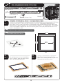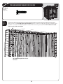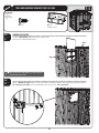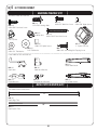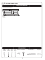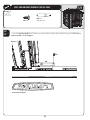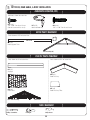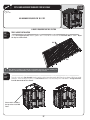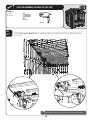
1
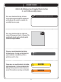
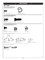
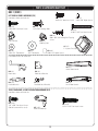
OUTDOOR STORAGE
MODEL N° 60014
Co
py
OWNER’S MANUAL
Keep this Identification Number in case you must contact our Customer Service Department.
IMPORTANT! PLEASE READ BEFORE BEGINNING ASSEMBLY
Dear Valued Customer,
We would like to congratulate you on your purchase of a Lifetime© Outdoor Storage Shed! We are
confident that you have made the perfect choice and you will be very pleased with your new storage
solution.
Lifetime© Outdoor Storage is part of the family of products created and manufactured by Lifetime®
Products, Inc. Like all of our products, you can be assured that the quality of your Lifetime Outdoor
Storage Shed is the best in the world! And, we back that quality up by offering the best warranty in the
business – A 10-year warranty that fully covers the Shed!
py
All of our Sheds are built with the highest-quality steel and high-density polyethylene (HDPE) parts. The
design and construction of our steel-reinforced double-Wall Panels is second to none. All of our exposed
steel parts and gables are powder coated and we use high-density polyethylene plastic. What makes
polyethylene so special? It has superior strength and durability, and, it won’t crack or degrade outdoors.
So now that you know the quality you are getting in a Lifetime Outdoor Storage Shed, please take the
time to READ THIS INSTRUCTION MANUAL!
We have taken great care in providing the best possible form of instructions to help you put your new
Outdoor Storage Shed together. Before you get started, PLEASE read the following preparation tips to
help you get started!
We can assure you, your construction experience will be a lot more enjoyable if you do!
Co
PREPARATION TIPS:
s4HElRSTSTEPISSIMPLEx2%,!89OUHAVEMADEAGREATPURCHASEBUT2OMEWASNOTBUILTINA
day. Plan to spend a good part of your weekend putting together your fine Outdoor Storage Shed. Our
PHILOSOPHYISIFITCOMESTOGETHERQUICKLYANDEASILYITSURELYWILLCOMEAPARTQUICKLYANDEASILY9OUR
Lifetime© Outdoor Storage Shed will surely last a long, long time, if you are patient, and take all the time
necessary to put it together as we have instructed.
s'RABAFRIENDTOJOININONTHEFUN4HISISNOTAONEPERSONENDEAVOR7EHAVEFOUNDTHATNOTONLYWILL
things go smoother if you have two or more people participating in the construction of the Shed, but it
will go quicker as well. So, the more the merrier!
s-AKESUREYOUHAVEALLTHETOOLSNECESSARYFORCONSTRUCTINGYOURNEW3HED4HEREISAh4OOLS2E
quired For This Assembly” list on page five of this Owner’s Manual.
s4HEPLASTICPIECESOFYOUR3HEDMAYBECOMEDAMAGEDBYOVERTIGHTENINGTHESCREWS4OAVOIDTHIS
damage, we strongly recommend the use of a low-powered power screwdriver or a drill that has an
adjustable clutch that is set on a low-torque setting. If neither is available, use a hand screwdriver. If a
HANDSCREWDRIVERISALLYOUHAVETAKESEVERALBREAKSxYOURWRISTWILLNEEDIT
s9OUWILLALSONEEDTWOSMALLLADDERSWHENITCOMESTIMETODOTHEROOF
INSTRUCTION #1065791
4/02/2010
2
IMPORTANT! PLEASE READ BEFORE BEGINNING ASSEMBLY
s"EFOREBEGINNINGASSEMBLYREMOVETHE0ARTS,ISTFROMTHECENTEROFTHIS/WNERS-ANUALANDTAKEAN
inventory of the parts included with your Outdoor Storage Shed. Also, read through the entire instruction manual. It’s always a great practice to get a feel for the flow of the process and to familiarize yourself with the parts involved. But, try not to get ahead of yourself and start the process out of order.
s&/,,/74(%).3425#4)/.3)./2$%2%VERYTHINGGOESTOGETHERINACERTAINORDERANDWEHAVE
learned what that correct order should be. In our state-of-the-art research and testing facility, we have
painstakingly created these instructions. The order of construction is there for a reason, and some parts
simply will not fit if built out of order. Just follow along with the order in the instructions and everything
will fit together and things will go very smooth.
s9/523(%$-534"%"5),4/.!,%6%,352&!#%)FTHESPOTYOUHAVECHOSENTOPLACEYOUR
wonderful new Outdoor Storage Shed is not level, the Shed will not assemble correctly! We recommend
ACONCRETEPATIOAWOODPLATFORMORCREATINGAPADWITHPEAGRAVEL9OUR3HEDISMEANTTOLASTALIFE
time, so provide the proper foundation for it before you start to build.
s"EFOREYOUBUILDITMAKESUREYOUAREALLOWEDTOBUILDIT#ONSULTALLBUILDINGCODESASWELLASCITY
and county ordinances, to ensure that you do not require a building permit to construct your Outdoor
Storage Shed. Proper building permit documentation may be required in your neighborhood, and it
would be quite unfortunate to learn this after your Outdoor Storage Shed is already built!
Now that you’re ready to begin the construction of your wonderful new Outdoor Storage Shed, step
back, take a deep breath, get yourself a large cold beverage and enjoy yourself. We guarantee that after
spending the right amount of time in building your Shed, you will be able to enjoy it for years to come.
Thanks for choosing Lifetime©, and have fun!
ABOUT LIFETIME PRODUCTS, INC.
Lifetime Products, Inc., has applied innovation and cutting-edge technology in plastics and
metals to create a family of affordable lifestyle products that feature superior strength and
durability. The world’s leading manufacturer of folding tables and chairs, Lifetime was founded in 1986 as the maker of portable basketball systems that revolutionized the industry with
patented technology. With diverse offerings such as outdoor storage sheds and steel utility
trailers, Lifetime continues to develop innovative products that outfit the way you live.
Lifetime makes the things you need for the lifestyle you want. By innovating products in and
around the home, Lifetime simplifies your everyday life and enables you to get the most out
of your free time.
3
REGISTER YOUR LIFETIME PRODUCT TODAY!
There are benefits to registering your Lifetime product. With our new online product registration form, it’s fast and easy! Register with us at www.lifetime.com
and enjoy these great benefits:
s2ECEIVEEXCLUSIVEMONEYSAVINGOFFERSFROM"UY,IFETIMECOMOURONLINESTOREASWELLAS.%7PRODUCTNOTIlCATIONSANDSPECIALCLOSEOUT
promotions!
s)NTHEUNLIKELYEVENTOFAPRODUCTRECALLORSAFETYMODIlCATIONWEWILLNOTIFYYOU
s2EGISTERINGYOURPRODUCTGUARANTEESYOUWARRANTYSERVICE)FYOUDONOTREGISTERYOURPRODUCTYOURWARRANTYRIGHTSWILLNOTBEDIMINISHED
But you will need to provide a sales receipt to verify your product purchase date before warranty service will be provided.
LIFETIME’S PROMISE TO YOU:
Maintaining your privacy is our long-standing policy at Lifetime. And you can rest assured that Lifetime will not sell or provide your
personal data to other third parties, or allow them to use your personal data for their own purposes.
We invite you to read our privacy policy at www.lifetime.com
REGISTER today!
**U.S. and Canada customers ONLY**
IF ASSISTANCE IS NEEDED,
DO NOT CONTACT THE STORE!
CALL OUR CUSTOMER SERVICE DEPARTMENT at 1 (800) 225-3865
HOURS: 7:00 a.m. to 5:00 p.m. Monday through Friday (Mountain Standard Time)
**Call, or visit our Web site for Saturday hours**
**For customers outside the U.S. or Canada, please contact the store for assistance.**
SAFETY INSTRUCTIONS
FAILURE TO FOLLOW THESE WARNINGS MAY RESULT IN SERIOUS INJURY OR
PROPERTY DAMAGE AND WILL VOID WARRANTY.
To ensure safety, do not attempt to assemble this product without following the instructions carefully. Check entire box and inside all
packing material for parts and/or additional instruction material. Before beginning assembly, read the instructions and identify parts
using the hardware identifier and parts list in this document. Proper and complete assembly, use and supervision are essential to
reduce the risk of accident or injury.
s$ONOTUSEORSTOREHOTOBJECTSSUCHASGRILLSBLOWTORCHESWELDINGEQUIPMENTETCNEARTHEPRODUCT
s)FUSINGALADDERDURINGASSEMBLYUSEEXTREMECAUTION
s4WOCAPABLEADULTSAREREQUIREDFORASSEMBLY)TISALSORECOMMENDEDTHATATHIRDADULTFUNCTIONASANINSTRUCTIONREADER
Most injuries are caused by misuse and/or not following instructions. Use caution when using this product.
4
BEFORE BEGINNING ASSEMBLY
Keep the hardware bags and their contents separate. If any parts are missing, call our
Customer Service Department.
2EADTHEh#ONGRATULATIONSvLETTERONPAGEIdentify and inventory all parts and hardware
using the parts and hardware lists and identifiers in this document.
*Two adults required to
complete assembly*
(+ one adult suggested as an instruction reader)
Only adults should set up the product. Do not allow children
in the set-up area until assembly is complete.
TOOLS REQUIRED FOR THIS ASSEMBLY
7/16"
3/8"
Adjustable
Rubber Mallet
(2)
(1)
(1)
(1)
6’ Ladder
(2)
Box Knife
(1)
Phillips
Plain
Screwdriver Screwdriver
(1)
Power Drill*
Work Light
Pliers
Flashlight
Hammer Drill*
(1)
(1)
(1)
(1)
(1)
*See “Screwdriver Notice” on page 7.
5
(1)
3/8" Masonry
Bit
2" x 4" x 7'
Leveling Board
(1)
Safety Glasses
(1 for each person)
Sheet of Wax Paper
(1)
(1)
ASSEMBLY GUIDES
Refer to the following areas throughout the instructions
to assist in the assembly process:
TOOLS AND HARDWARE REQUIRED FOR THIS PAGE
SEC
This area is located at the top, left-hand
corner of the page and indicates which tools
and hardware are needed to complete the
assembly steps on a page.
This area is located at the top, right-hand
corner of the page and shows an image of the
product with shaded parts indicating which
section is being assembled.
This area is usually located in the bottom,
left-hand corner of a step and indicates that
special attention is needed to perform a
particular part of a step.
!
#
Note:
CAUTION
These areas are usually located in the bottom,
right-hand corner of a step and indicate that
damage to the product or serious injury may
occur if the caution or warning is not heeded.
WARNING
6
IMPORTANT NOTICES
Level Surface Notice:
Surface must be leveled before installation. We recommend building a level work space with a concrete
or patio style surface. If the surface is not properly leveled, the Outdoor Shed will not assemble correctly.
Proper surface leveling will save you time in the long run, so please do not ignore this step.
Building Code Notice:
Consult all local building codes, as well as city and county ordinances, to ensure that the construction of the
Outdoor Shed does not require a building permit. Proper building permit documentation may be required in
your neighborhood, and it would be unfortunate to learn this after constructing the Shed.
Screwdriver Notice:
9OUMAYUSEA0HILLIPSHEADSCREWDRIVERBITANDAPOWERSCREWDRIVERORDRILLINSTEADOFAHAND
screwdriver. However, be aware that the plastic pieces of your Shed can be damaged by overtightening of
screws. To avoid damage we strongly recommend the use of a low-powered power screwdriver or a drill that
has an adjustable clutch that is set on a low torque setting. If neither is available, use a hand screwdriver. In
any case use caution to avoid overtightening the screws.
Floor Puncture Notice:
Sharp objects may damage your floor. If resting sharp, heavy objects on your Shed floor, place a block of
wood between the sharp object and floor.
CAUTION:
If more than six (6) inches of snow accumulate on the roof of the shed, carefully remove the snow to avoid
possible roof collapse. While standing on the ground, remove the snow from the roof with a broom or snow
shovel. Do not stand on the roof to remove snow.
7
PARTS & HARDWARE LIST
BOX 1
SHED PARTS BOX
ID
!'2
!&8
AHD
AHH
!'1
!',
AHE
Description
/UTER&LOOR0ANEL
#ENTER&LOOR0ANEL
Wall Panel
Window Wall Panel
2OOF0ANEL
#ORNER7ALL0ANEL
Window
Qty
5
1
1
ID
Description
BYJ LEFT DOOR ASSEMBLY HARDWARE
"93
/UTER$OOR(ANDLE
"92
)NNER$OOR(ANDLE
"9:
Xv0AN(EAD3CREW
!$7
Xv0AN(EAD3CREW
!$*
v#AP.UT
!%"
v&LAT7ASHER
!%%
X&LAT7ASHER
!$+
#AP.UT
","
vXv#ARRIAGE"OLT
":!
Xv-ACHINE3CREW
":"
Xv.YLON3PACER
#!6
Xv.YLON3PACER
"9.
$OOR,ATCH
"9/
$OOR,ATCH"RACKET
"90
$EADBOLT,ATCH"RACKET
"91
$EADBOLT,ATCH
#(+
Xv3ELF$RILLING3ELF4APPING3CREW
CIF
End Cap
BYK RIGHT DOOR ASSEMBLY HARDWARE
"93
/UTER$OOR(ANDLE
"92
)NNER$OOR(ANDLE
"9:
Xv0AN(EAD3CREW
!$7
Xv0AN(EAD3CREW
!%%
Xv&LAT7ASHER
BBI
Inside Door Handle
#(+
Xv3ELF$RILLING3ELF4APPING3CREW
CIF
End Cap
BYL TRUSS, REAR GABLE, & ROOF INSTALLATION HARDWARE
!$:
vXv0AN(EAD3CREW
"94
'ABLETO2OOF#LIP
!$6
vXv0AN(EAD3CREW
BYU SMALL PARTS BOX
"97
2OOF%ND#AP
"98
2OOF%ND#AP&ILTER
"99
2OOF3UPPORT4UBE
BZC
Tube of Caulking
!)8
7OOD3HIM
AIW
Wood Block
BYC FLOOR ASSEMBLY HARDWARE
"1#
Xv0AN(EAD3CREW
!(/
$OOR(INGE"USHING
BYE WALL INSTALLATION HARDWARE
!$:
vXv0AN(EAD3CREW
!$6
vXv0AN(EAD3CREW
BYD TRUSS ASSEMBLY HARDWARE (x2)
!$9
Xv0AN(EAD3CREW
!$+
#AP.UT
!$*
v#AP.UT
"85
4RUSS#ONNECTOR!
"86
4RUSS#ONNECTOR"
"87
4RUSS#ONNECTOR"RACKET
!$(
v4HREADED2OD
BYF GABLE ASSEMBLY HARDWARE
!$:
vXv0AN(EAD3CREW
!$6
vXv0AN(EAD3CREW
BYG WINDOW INSTALLATION HARDWARE
!$:
vXv0AN(EAD3CREW
AIS
Window Latch Bracket
BYH TOOL BAG
ARA
1/8” Drill Bit
!$#
0HILLIPS"IT
BYI DOOR & ENTRY GABLE INSTALLATION HARDWARE
!$:
vXv0AN(EAD3CREW
!(0
#OTTER0IN
"&9
vXv0AN(EAD3CREW
!$*
v#AP.UT
"8:
v.YLON7ASHER
!$8
Xv0AN(EAD3CREW
"9-
3TRIKE0LATE
1
1
1
Qty
1
1
1
BOX 2
SHED PARTS BOX
!'1
!',
!':
!'/
!'&
!'(
!')
"96
1
2OOF0ANEL
#ORNER7ALL0ANEL
2IGHT$OOR
,EFT$OOR
%NTRY'ABLE
2EAR'ABLE
2EAR'ABLE
3KYLIGHT
BZD METAL KIT
!&'
!&(
AFM
"88
AFE
"9!
"9"
"84
#((
#()
8
4RUSS"RACE
4RUSS'UTTER#HANNEL
Wall Support Channel
2EAR7ALL3UPPORT3QUARE4UBE
Door Header
,EFT!NGLED$OOR*AMB
2IGHT!NGLED$OOR*AMB
7INDOW7ALL3UPPORT#HANNEL
$OOR(INGE4UBE
$OOR3QUARE4UBE
5
1
PARTS IDENTIFIER
BOX 1
SHED PARTS BOX
0ARTSSHOWNATOFACTUALSIZE
AGRX
Outer Floor Panel
AFX (x1)
Center Floor Panel
AGQX
Roof Panel
AHE (x1)
Window
AHD (x5)
Wall Panel
AHH (x1)
Window Wall Panel
AGL (x1)
Corner Wall Panel
SMALL PARTS BOX [BYU]
0ARTSSHOWNATOFACTUALSIZE
5NLESSNOTEDOTHERWISE
BYXX
Roof End Cap Filter
BYWX
Roof End Cap
*BZC (x1)
Tube of Caulking
*AIXX
Wood Shim
0ARTSHOWNATOFACTUALSIZE
26 11/16”
*AIW (x1)
Wood Block
BYY (x6)
Roof Support Tube
9
PARTS IDENTIFIER
BOX 1 (CONT.)
FLOOR ASSEMBLY HARDWARE [BYC]
Hardware shown at actual size
BQCX
Xv0AN(EAD3CREW
AHOX
Door Hinge Bushing
WALL INSTALLATION HARDWARE [BYE]
Hardware shown at actual size
ADZ (x80)
vXv0AN(EAD3CREW
ADV (x6)
vXv0AN(EAD3CREW
TRUSS ASSEMBLY HARDWARE [BYD] (x2)
Hardware shown at actual size
ADYX
Xv0AN(EAD3CREW
ADKX
#AP.UT
ADJX
v#AP.UT
0ARTSSHOWNATOFACTUALSIZE
BXU (x1)
Truss Connector A
BXV (x1)
Truss Connector B
BXW (x1)
Truss Connector Bracket
0ARTSHOWNATOFACTUALSIZE
9 3/4”
ADH (x1)
v4HREADED2OD
10
PARTS IDENTIFIER
BOX 1 (CONT.)
GABLE ASSEMBLY HARDWARE [BYF]
Hardware shown at actual size
ADZX
vXv0AN(EAD3CREW
ADV (x6)
vXv0AN(EAD3CREW
WINDOW ASSEMBLY HARDWARE [BYG]
Hardware shown at actual size (*Unless noted otherwise)
ADZX
vXv0AN(EAD3CREW
*AIS (x1)
Window Latch
TOOL BAG [BYH]
Hardware shown at actual size
ARA (x1)
1/8” Drill Bit
ADC (x1)
0HILLIPS"IT
DOOR & ENTRY GABLE INSTALLATION HARDWARE [BYI]
Hardware shown at actual size
ADZ (x17)
vXv0AN(EAD3CREW
AHPX
Cotter Pin
BFY (x5)
vXv0AN(EAD3CREW
ADXX
Xv0AN(EAD3CREW
BXZ (x16)
v.YLON7ASHER
0ARTSHOWNATOFACTUALSIZE
BYM (x1)
Strike Plate
11
ADJ (x5)
v#AP.UT
PARTS & HARDWARE IDENTIFIER
BOX 1 (CONT.)
LEFT DOOR ASSEMBLY HARDWARE [BYJ]
Hardware shown at actual size
ADW (x5)
Xv0AN(EAD3CREW
BZAX
Xv-ACHINE3CREW
BLBX
vXv#ARRIAGE"OLT
CAVX
Xv.YLON3PACER
BYZX
Xv0AN(EAD3CREW
CHK (x1)
Xv3ELF$RILLING3ELF4APPING
Screw
ADJX
#AP.UT
ADKX
#AP.UT
CIF (x1)
1” Square End Cap
AEE (x9)
Xv&LAT7ASHER
AEBX
v&LAT7ASHER
BZBX
Xv.YLON3PACER
0ARTSHOWNATOFACTUALSIZE
BYS (x1)
Outer Door Handle
BYN (x1)
Door Latch
BYQX
Deadbolt Latch
BYO (x1)
Door Latch Bracket
BYPX
Deadbolt Latch Bracket
BYR (x1)
Inner Door Handle
TRUSS, REAR GABLE, & ROOF INSTALLATION HARDWARE [BYL]
Hardware shown at actual size
ADZ (x91)
vXv0AN(EAD3CREW
(Not all screws will be used)
ADVX
vXv0AN(EAD3CREW
BYT (x16)
'ABLETO2OOF#LIP
12
PARTS & HARDWARE IDENTIFIER
BOX 1 (CONT.)
RIGHT DOOR ASSEMBLY HARDWARE [BYK]
Hardware shown at actual size
ADW (x1)
X0AN(EAD3CREW
BYZX
X0AN(EAD3CREW
CIF (x1)
1” Square End Cap
AEE (x1)
Xv&LAT7ASHER
CHK (x1)
Xv3ELF$RILLING3ELF4APPING
Screw
0ARTSHOWNATOFACTUALSIZE
0ARTSHOWNATOFACTUALSIZE
BYR (x1)
Inner Handle
BBI (x1)
Inside Door Handle
BYS (x1)
Outer Handle
BOX 2
SHED PARTS BOX
0ARTSSHOWNATOFACTUALSIZE
AGO (x1)
Left Door
AGQX
Roof Panel
AGLX
Corner Wall Panel
AGZ (x1)
Right Door
AGF (x1)
%NTRY'ABLE
AGH (x1)
2EAR'ABLE
BYV (x1)
Skylight
13
AGI (x1)
2EAR'ABLE
PARTS & HARDWARE IDENTIFIER
BOX 2 (CONT.)
METAL KIT [BZD]
0ARTSSHOWNATOFACTUALSIZE
43 1/4”
40”
AFGX
Truss Brace
AFHX
4RUSS'UTTER#HANNEL
67 3/4”
AFM (x5)
Wall Support Channel
78 3/8”
BXX (x1)
Rear Wall Support Square Tube
54 3/8”
AFE (x1)
Entry Header Bar
70 7/8”
BYA (x1)
Left Angled Door Jamb
72 3/8”
BYB (x1)
Right Angled Door Jamb
49”
BXT (x1)
Window Wall Support Channel
77”
CHHX
Door Hinge Tube
75”
CHIX
Door Square Tube
14
SEC
TOOLS AND HARDWARE REQUIRED FOR THIS PAGE
1
Concrete (1 cu. yd.)
SEC
SITE PREPARATION - CONCRETE PLATFORM PREPARATION
1.1
The actual dimensions of your shed (at its widest and longest points) are 7’ x 7’. Ensure you select a site that will
accommodate these measurements. The base of the shed is slightly smaller than this, so you will need to create
ALEVELSURFACETHATISATLEASTv7IDEXv,ONG7ERECOMMENDUSINGALEVELCEMENTORPATIOSTYLE
surface. This will provide the best long-term performance for your shed.
7’
7’
83 3/8”
7’
81 1/2”
7’
Front
!
Note: Surface must be leveled before installation. If the surface is not properly leveled, the shed will not assemble or
function correctly. Proper surface leveling will save you time in the long run, so please do not ignore this step.
!
Note: Any platform or similar structure should be built above ground in order to avoid water pooling inside the shed.
15
SEC
TOOLS AND HARDWARE REQUIRED FOR THIS PAGE
1
2” x 4” x 81 1/2” Treated BoardX
2” x 4” x 80 3/8” Treated Board (x7)
16d 3” Common NailX
ALTERNATIVE SITE PREPARATION: OPTION 1 - WOOD PLATFORM ASSEMBLY
SEC
Ensure you use lumber that is treated and approved for outdoor use. Build outside frame to 81 1/2” Wide x 83 3/8”
Long.
1.2
!
Note: Whenever possible you should use the surfaces described on Page 7. When this is not possible, we recommend you use a wood platform or a
filled wood frame.
!
Note: All lumber must be rated for outdoor use.
81 1/2”
83
8”
3/
”
16
Front
”
16
”
16
”
16
”
16
nt
Fro
To ensure studs are in the correct
location to nail plywood in the next step,
start measuring at the corner 16”, and
then measure from center to center.
Place the 2” x 4” x 80 3/8” boards on the
inside of the frame. Nail each board in place
with the 16d nails.
!
Note: Surface must be leveled before installation. If the surface is not properly leveled, the Outdoor Shed will not assemble or function correctly.
Proper surface leveling will save you time in the long run, so please do not ignore this step.
16
SEC
TOOLS AND HARDWARE REQUIRED FOR THIS PAGE
1
33 1/2” x 83 3/8” x 3/4” Treated Plywood (x1)
48” x 83 3/8” x 3/4” Treated Plywood (x1)
SEC
1.3
!
8d 1 1/2” Common NailX
ALTERNATIVE SITE PREPARATION: OPTION 1 - WOOD PLATFORM ASSEMBLY (CONT)
Square up the frame by measuring from corner to corner. Measurement A should equal Measurement B.
Note: All lumber must be rated for outdoor use.
A
B
SEC
1.4
Cut Plywood into sizes called for above. Arrange the Plywood according to the diagram and nail into place with
DXvNAILS0LACEPLATFORMINTHEDESIREDLOCATION)FPLATFORMDOESNOTRESTLEVELONTHEGROUNDBUILDUP
LOWPOINTSWITHLOOSEDIRTUNTILPLATFORMISSTABLE$RILLTHREEEVENLYSPACEDvDRAINHOLESINPLYWOODBETWEEN
EACHvXv
33
1/2
”x
83
3/8
”
48”
x 83
3/8
”
nt
Fro
ont
Fr
17
SEC
TOOLS AND HARDWARE REQUIRED FOR THIS PAGE
1
2” x 4” x 81 1/2”X
2” x 6” x 76 3/8”X
L-BracketX
8d 1 1/2” Common Nail (x16)
1.5
ALTERNATIVE SITE PREPARATION: OPTION 2 - FILLED WOOD FRAME ASSEMBLY
#UTOUTSIDEFRAMETO7IDEXv,ONGOUTSIDEDIMENSIONSLay boards flat so widest part faces up.
Ensure frame is level. Square up the frame by measuring from corner to corner. Measurement A should equal
-EASUREMENT".AILAN,"RACKETONEACHCORNEROFTHEFRAMEWITHDXv#OMMON.AILS0LACEPLATFORM
INTHEDESIREDLOCATION)FPLATFORMDOESNOTRESTLEVELONTHEGROUNDBUILDUPLOWPOINTSWITHLOOSEDIRTORh0EA
'RAVELvUNTILPLATFORMISSTABLE
!
Note: Whenever possible you should use the surfaces described on Page 7.
!
Note: All lumber must be rated for outdoor use.
83 3/8”
81 1/2”
B
76 3/8”
SEC
Pea Gravel (7.5 Cubic Feet)
2” x 6”
Boards
A
Front
SEC
1.6
SEC
Once all boards are level and do not wobble,
PACKh0EA'RAVELvAROUNDTHEOUTSIDEOFTHE
frame, and slope away from frame.
1.7
2” x 4” x 7’ Leveling Board (x1)
18
.OWlLLTHEINSIDEOFTHEFRAMEWITHh0EA
'RAVELv5SEALEVELINGBOARDTOSCRAPEOFFEXTRA
fill material and to level the surface.
SEC
2
FLOOR ASSEMBLY
HARDWARE REQUIRED (BYC)
Hardware shown at actual size
BQCX
Xv0AN(EAD3CREW
AHOX
Door Hinge Bushing
METAL PARTS REQUIRED
NO METAL PARTS REQUIRED FOR THIS SECTION
PLASTIC PARTS REQUIRED
0ARTSSHOWNATOFACTUALSIZE
AGRX
Outer Floor Panel
AFX (x1)
Center Floor Panel
TOOLS REQUIRED
Phillips Screwdriver
Safety Glasses
19
SEC
TOOLS AND HARDWARE REQUIRED FOR THIS PAGE
2
NO HARDWARE REQUIRED FOR THIS PAGE
SEC
FLOOR ASSEMBLY
2.1
Lay an Outer Floor Panel (AGR) flat on the ground. Hold a Center Floor Panel (AFX) at an angle as shown and fit the
tabs into the slots. Lay the Center Floor Panel flat.
AFX
AGR
CAUTION
Sharp objects may damage your floor. If resting
sharp, heavy objects on your shed floor, place a
block of wood between the sharp object and floor.
SEC
2.2
Hold the second Outer Floor Panel (AGR) at an angle as shown and fit the its tabs between the tabs on the Center
Floor Panel. Lay the Outer Floor Panel flat.
AGR
20
SEC
TOOLS AND HARDWARE REQUIRED FOR THIS PAGE
AHOX
SEC
2.3
Decide which end will be the front of your shed. Lift the Floor Panels up enough to slide the Door Hinge Bushings
(AHO) under and up through the holes in the front Outer Floor Panel as shown.
AHO
AHO
AHO
21
2
SEC
TOOLS AND HARDWARE REQUIRED FOR THIS PAGE
BQCX
SEC
2.4
Face the seam of the two adjacent Floor Panels. Insert one (1) #8 x 1/2” Pan-Head Screw (BQC) into the divot near
the seam of the Outer Floor Panel and down into the tab of the adjacent Center Floor Panel at the locations
indicated. Do not overtighten.
2.4
22
2
SEC
TOOLS AND HARDWARE REQUIRED FOR THIS PAGE
2
IF YOU PLAN ON ANCHORING YOUR SHED, CHECK WITH YOUR LOCAL HARDWARE STORE
FOR SUITABLE HARDWARE.
SEC
2.5
ANCHORING THE SHED
If you plan on anchoring your shed, you can anchor it to your platform through the four indentations near the
corners of the floor. The anchoring hardware used depends on the platform. If you have a concrete platform,
WERECOMMENDUSINGFOURv!NCHOR"OLTSANDFOURvXv&ENDER7ASHERS)FYOUHAVEAWOOD
FRAMEDPLATFORMWERECOMMENDUSINGFOURv,AG"OLTSANDFOURvXv&ENDER7ASHERSDo not
exceed a 3/8” diameter bolt. Refer to your local hardware store for this hardware.
WARNING
Failure to anchor the shed may result in property
damage and/or personal injury.
23
SEC
3
TRUSS ASSEMBLY
HARDWARE REQUIRED (BYD (x2))
Hardware shown at actual size
ADYX
Xv3CREW
ADKX
#AP.UT
ADJX
v#AP.UT
0ARTSHOWNATOFACTUALSIZE
BXUX
Truss Connector A
BXVX
Truss Connector B
BXWX
Truss Connector Bracket
0ARTSHOWNATOFACTUALSIZE
9 3/4”
ADHX
v4HREADED2OD
METAL PARTS REQUIRED
0ARTSSHOWNATOFACTUALSIZE
5NLESSINDICATEDOTHERWISE
43 1/4”
AFHX
4RUSS'UTTER#HANNEL
40”
AFGX
Truss Brace
TOOLS REQUIRED
Phillips Screwdriver
7/16” Wrench
3/8” Wrench
24
Safety Glasses
SEC
TOOLS AND HARDWARE REQUIRED FOR THIS PAGE
3
ADY (x8)
ADK (x8)
SEC
TRUSS ASSEMBLY
3.1
)NSERTFOUR#10 x 3/8” Pan-Head Screws (ADY) through a Truss Connector A (BXU) as shown.
BXU
ADY
ADY
ADY
ADY
SEC
3.2
0LACETWOTruss Gutter Channels (AFH) over the Truss Connector as shown and insert the four Screws through the
FOURHOLESINTHE4RUSS'UTTER#HANNELS,IGHTLYSECURETHE3CREWSWITHFOUR #10 Cap Nuts (ADK). Hand tighten
only in this step.
AFH
AFH
ADK
25
SEC
TOOLS AND HARDWARE REQUIRED FOR THIS PAGE
3
ADY (x8)
ADK (x8)
SEC
3.3
Insert a Truss Connector Bracket (BXW) into the slot in Truss Connector A as shown.
BXW
SEC
3.4
Place Truss Connector B (BXV)OVERTHE4RUSS#ONNECTOR"RACKETANDTHE4RUSS'UTTER#HANNELSASSHOWN)NSERT
FOUR#10 x 3/8” Pan-Head Screws (ADY) through a Truss Connector B as shown and lightly secure the Screws with
FOUR #10 Cap Nuts (ADK). Hand tighten only in this step.
26
SEC
TOOLS AND HARDWARE REQUIRED FOR THIS PAGE
3
7/16”
3/8”
ADJ X
ADY (x8)
ADK (x8)
SEC
3.5
With the Truss Assembly on its side, align the holes in a Truss Brace (AFG)WITHTHOSEINTHE4RUSS'UTTER#HANNELS
ASSHOWN3ECUREWITHFOUR#10 x 3/8” Pan-Head Screws (ADY) and FOUR #10 Cap Nuts (ADK). Hand tighten only in
this step.
AFG
SEC
3.6
With the Truss Assembly on its side, slide a 1/4” Threaded Rod (ADH) through the Truss Brace and Truss Connector
"RACKETASSHOWN3ECURETHETOPANDBOTTOMOFTHEv4HREADED2ODWITHA1/4” Cap Nut (ADJ). Tighten securely.
Finally tighten all hardware. Set aside. Repeat this section for the second Truss Assembly.
ADH
ADJ
ADJ
27
SEC
4
WALL INSTALLATION
HARDWARE REQUIRED (BYE)
Hardware shown at actual size
ADZ (x80)
vXv0AN(EAD3CREW
ADV (x6)
vXv0AN(EAD3CREW
METAL PARTS REQUIRED
0ARTSSHOWNATOFACTUALSIZE
67 3/4”
AFM (x5)
Wall Panel Support Channel
49”
BXT (x1)
Window Wall Panel Support Channel
78 3/8”
BXX (x1)
Rear Wall Support Square Tube
PLASTIC PARTS REQUIRED
0ARTSSHOWNATOFACTUALSIZE
AGLX
Corner Wall Panel
AHD (x5)
Wall Panel
AHH (x1)
Window Wall Panel
TOOLS REQUIRED
Phillips Screwdriver
Safety Glasses
*AIW Wood Block (x1) (Provided)
28
SEC
TOOLS AND HARDWARE REQUIRED FOR THIS PAGE
*AIW (x1)
Wood Block
SEC
4.1
4
ADZ (x10)
WALL PANEL INSTALLATION
Insert the tabs at the bottom of a Corner Wall Panel (AGL) into the holes in the slots on the front of the right, front
corner of the Floor as shown. Slide the Panel to the right. Fold the Corner Wall Panel and snap the tabs at the
bottom of the Panel down into the two slots along the right border of the Floor. If necessary, place the Wood Block
(AIW) underneath the Floor, directly below the tab to be inserted, when snapping the tabs in place.
AGL
AIW
SEC
4.2
One at a time, insert two Wall Panels (AHD) into the holes in the slots along the right side of the shed, and slide the
Panels toward the Corner Wall Panel. The Window Wall Panel (AHH) may be inserted on either side of the shed. Ensure the
tops of the Wall Panels are even with the Corner Wall Panel and the holes align. Insert 1/4” x 5/8” Pan-Head Screws
(ADZ) through the holes to fasten the Panels together as shown.
AHD
AHD
ADZ
ADZ
!
Note: A second person should apply pressure on the opposite side of the
Wall Panels for easier insertion of the Screw. Do not overtighten Screw.
29
*AIW (x1)
Wood Block
SEC
TOOLS AND HARDWARE REQUIRED FOR THIS PAGE
ADZ (x15)
SEC
4.3
Slide and snap another Corner Wall Panel (AGL) into place in the same manner as you did earlier. Fasten with the
required hardware. If necessary, place the Wood Block (AIW) underneath the Floor, directly below the tab to be
inserted, when snapping the tabs in place.
AGL
SEC
4.4
One at a time, insert two Wall Panels (AHD) along the rear border of the Floor. Ensure the tops are level and the
holes line up before fastening the Panels together with the required hardware.
AHD
AHD
30
4
*AIW (x1)
Wood Block
SEC
TOOLS AND HARDWARE REQUIRED FOR THIS PAGE
4
ADZ (x15)
SEC
4.5
Fold a Corner Wall Panel (AGL). Slide and snap it into place in the same manner as you did earlier. Fasten with the
required hardware. If necessary, place the Wood Block (AIW) underneath the Floor, directly below the tab to be
inserted, when snapping the tabs in place.
AGL
SEC
4.6
Snap a Window Wall Panel (AHH) and a Wall Panel (AHD) into place along the right side of the shed. The Window Wall
Panel may be inserted on either side of the shed. Ensure the top of the Wall Panels are even with the Corner Wall Panel
and the holes align. Insert 1/4” x 5/8” Pan-Head Screws (ADZ) through the holes of the Wall Panels to fasten them
together.
AHH
AHD
31
SEC
TOOLS AND HARDWARE REQUIRED FOR THIS PAGE
*AIW (x1)
Wood Block
4
ADZX
SEC
4.7
Fold a Corner Wall Panel (AGL). Slide and snap it into place in the same manner as you did earlier. Fasten with the
required hardware. If necessary, place the Wood Block (AIW) underneath the Floor, directly below the tab to be
inserted, when snapping the tabs in place.
AGL
SEC
4.8
Insert a Wall Support Channel (AFM) into the groove directly below the truss notch of each Wall Panel, including the
rear Wall Panels, as shown. Secure using the required hardware. Insert a Window Wall Support Channel (BXT) directly
below the Window in the Window Wall Panel using the required hardware.
ADZ
Truss Notch
ADZ
AFM
ADZ
ADZ
32
SEC
TOOLS AND HARDWARE REQUIRED FOR THIS PAGE
4
ADV (x6)
SEC
4.9
Align the holes in the Rear Wall Support Square Tube (BXX) with the screw bosses along the top of the rear Wall Panels
as shown. Secure the Rear Wall Support Tube to the Wall Panels using six (6) 1/4” x 1 1/8” Pan-Head Screws (ADV).
Tighten securely, but do not overtighten.
BXX
The indented, rectangular holes face the
Wall Panels.
33
SEC
5
WINDOW INSTALLATION
HARDWARE REQUIRED (BYG)
Hardware shown at actual size (*Unless indicated otherwise)
ADZX
vXv0AN(EAD3CREW
*AIS (x1)
Window Latch
METAL PARTS REQUIRED
NO METAL PARTS REQUIRED FOR THIS SECTION
PLASTIC PARTS REQUIRED
0ARTSHOWNATOFACTUALSIZE
AHE (x1)
Window
TOOLS REQUIRED
Phillips Screwdriver
Safety Glasses
34
ADZX
SEC
TOOLS AND HARDWARE REQUIRED FOR THIS PAGE
AIS (x1)
(Not to scale)
SEC
WINDOW INSTALLATION
5.1
Insert the Window (AHE) down between the ridges of the
opening in the Window Wall Panel.
Ridges
Ridges
!
Note: The curved end of the Window goes at the top and faces
toward the interior of the Shed.
SEC
5.2
Attach a Window Latch (AIS)ABOVETHELEFTCORNEROFTHE7INDOWASSHOWN7HENTIGHTENINGTHETWO1/4” x
5/8” Pan-Head Screws (ADZ), ensure the Window Latch slides freely. Do not overtighten.
AIS
ADZ
ADZ
35
5
SEC
6
LEFT DOOR ASSEMBLY
HARDWARE REQUIRED (BYJ)
Hardware shown at actual size
BLBX
vXv#ARRIAGE"OLT
ADW (x5)
Xv0AN(EAD3CREW
ADKX
#AP.UT
BZAX
Xv-ACHINE3CREW
CAVX
Xv.YLON3PACER
BYZX
Xv0AN(EAD3CREW
ADJX
#AP.UT
BZBX
Xv.YLON3PACER
AEE (x9)
Xv&LAT7ASHER
AEBX
v&LAT7ASHER
CIF (x1)
1” Square End Cap
CHK (x1)
Xv3ELF$RILLING3ELF4APPING3CREW
0ARTSSHOWNATOFACTUALSIZE
BYS (x1)
Outer Door Handle
BYN (x1)
Door Latch
BYQX
Deadbolt Latch
BYO (x1)
Door Latch Bracket
BYPX
Deadbolt Latch Bracket
METAL PARTS REQUIRED (BZD)
0ARTSHOWNATOFACTUALSIZE
77”
CHH (x1)
Door Hinge Tube
75”
CHI (x1)
Door Square Tube
36
BYR (x1)
Inner Door Handle
SEC
6
6
LEFT DOOR ASSEMBLY (CONT.)
PLASTIC PARTS REQUIRED
0ARTSHOWNATOFACTUALSIZE
AGO (x1)
Left Door
6.1
6.2
TOOLS REQUIRED
Phillips
Screwdriver
Plain
7/16”
Screwdriver Wrench
3/8”
Wrench
Electric Drill
Rubber Mallet
37
1/8” Drill Bit (ARA) (x1)
Safety Glasses
SEC
TOOLS AND HARDWARE REQUIRED FOR THIS PAGE
CIF (x1)
SEC
LEFT DOOR ASSEMBLY
6.1
Rest the Left Door (AGO) with the front side down. Slide the Door Hinge Tube (CHH) down into the Left Door as
shown.
CHH
Rear View
AGO
SEC
Insert a 1” Square End Cap (CIF) into one of the ends of the Door Square Tube (CHI) as shown.
6.2
CHI
CIF
38
6
SEC
TOOLS AND HARDWARE REQUIRED FOR THIS PAGE
CHK (x1)
SEC
6.3
Slide the Door Square Tube up into the hole at the bottom of the Door until the 1” Square End Cap is flush with
the bottom of the Door. Secure the Door Square Tube in place using one (1) #10 x 3/4” Self-Drilling/Self-Tapping
Screw (CHK) at the location shown.
Rear View
1” Square End Cap
CHK
!
Note: You may need to use a rubber mallet to help insert the Door Square Tube.
39
6
SEC
TOOLS AND HARDWARE REQUIRED FOR THIS PAGE
ADW (x1)
6
BYZX
AEE (x5)
3/8”
CAVX
BZAX
ADKX
BLBX
SEC
6.4
!TTACHTHE)NNERAND/UTER$OOR(ANDLESTOTHE$OORUSINGTWO#10 x 1 3/4” Pan-Head Screws (BYZ) and one (1)
#10 x 3/4” Pan-Head Screw (ADW)ANDTHREE#10 x 1/2” Flat Washers (AEE) as shown.
Rear View
BYZ
ADW
AEE
AEE
AEE
BYR
BYS
SEC
6.5
&IRSTINSERTTHETWO1/4” x 5/8” Carriage Bolts (BLB) through the Door Latch Bracket (BYO) as shown, then connect
the Door Latch (BYN) to the Door Latch Bracket using the required hardware.
ADK
AEE
CAV
BZA
BYN
WARNING
BYO
BLB
Insert these two Carriage Bolts first.
40
Do not overtighten the Cap Nut. If the end of
the Bolt breaks through the plastic cap, call our
Customer Service Department. Exposed threads
on the end of the Bolt may cause serious injuries.
SEC
TOOLS AND HARDWARE REQUIRED FOR THIS PAGE
7/16”
AEBX
ADJX
SEC
6.6
Attach the Latch Mechanism to the Left Door as shown using the required hardware.
Rear View
ADJ
AEB
WARNING
Do not overtighten the Cap Nut.
41
6
SEC
TOOLS AND HARDWARE REQUIRED FOR THIS PAGE
ADWX
6
AEEX
ARA (x1)
BZBX
SEC
6.7
Using the 1/8” Drill Bit (ARA) (Provided), drill a hole through the plastic of the bottom end of the Left Door and into
the metal tube inside the Door at the locations shown. Do not drill all the way through the Door. Repeat this step for the
top end of the Left Door.
Drill holes here.
Rear View
SEC
6.8
Connect a Deadbolt Latch Bracket (BYP) and Deadbolt Latch (BYQ) to the top of the Door as shown using the required
hardware. Repeat this step for the bottom of the Door.
Rear View
ADW
ADW
AEE
AEE
BYQ
BYP
BZB
BYQ
BZB
BYP
Top
Bottom
42
SEC
7
RIGHT DOOR ASSEMBLY
HARDWARE REQUIRED (BYK)
Hardware shown at actual size
BYZX
X0AN(EAD3CREW
ADW (x1)
X0AN(EAD3CREW
AEE (x1)
Xv&LAT7ASHER
CIF (x1)
1” Square End Cap
0ARTSHOWNATOFACTUALSIZE
CHK (x1)
Xv3ELF$RILLING3ELF4APPING3CREW
0ARTSSHOWNATOFACTUALSIZE
BYR (x1)
Inner Handle
BYS (x1)
Outer Handle
BBI (x1)
Inside Door Handle
METAL PARTS REQUIRED (BZD)
0ARTSHOWNATOFACTUALSIZE
77”
CHH (x1)
Door Hinge Tube
75”
CHI (x1)
Door Square Tube
PLASTIC PARTS REQUIRED
0ARTSHOWNATOFACTUALSIZE
AGZ (x1)
Right Door
TOOLS REQUIRED
Phillips Screwdriver
7/16” Wrench
Electric Drill
43
Rubber Mallet
Safety Glasses
SEC
TOOLS AND HARDWARE REQUIRED FOR THIS PAGE
CIF (x1)
SEC
RIGHT DOOR ASSEMBLY
7.1
Rest the Right Door (AGZ) with the front side down. Slide the Door Hinge Tube (CHH) down into the Right Door as
shown.
CHH
AGZ
SEC
Insert a 1” Square End Cap (CIF) into one of the ends of the Door Square Tube (CHI) as shown.
7.2
CHI
CIF
44
7
SEC
TOOLS AND HARDWARE REQUIRED FOR THIS PAGE
7
CHK (x1)
SEC
7.3
Slide the Door Square Tube up into the hole at the bottom of the Door until the 1” Square End Cap is flush with
the bottom of the Door. Secure the Door Square Tube in place using one (1) #10 x 3/4” Self-Drilling/Self-Tapping
Screw (CHK) at the location shown.
Rear View
1” Square End Cap
!
CHK
Note: You may need to use a rubber mallet to help insert the Door Square Tube.
45
SEC
TOOLS AND HARDWARE REQUIRED FOR THIS PAGE
BYZX
ADW (x1)
BBI (x1)
(Not to scale)
AEE (x1)
SEC
7.4
Connect the Inner and Outer Handles (BYR & BYS) and Inside Handle (BBI) to the Door using the required hardware.
Set aside.
Back of Door
AGZ
BYZ
BBI
ADW
AEE
BYR
BYS
46
7
SEC
8
GABLE ASSEMBLY
HARDWARE REQUIRED (BYF)
Hardware shown at actual size
ADZX
vXv0AN(EAD3CREW
ADV (x6)
vXv0AN(EAD3CREW
METAL PARTS REQUIRED
0ARTSHOWNATOFACTUALSIZE
54 3/8”
AFE (x1)
Entry Header Bar
PLASTIC PARTS REQUIRED
0ARTSSHOWNATOFACTUALSIZE
(Front View)
AGF (x1)
%NTRY'ABLE
AGH (x1)
2EAR'ABLE
(Rear View)
AGI (x1)
2EAR'ABLE
(Rear View)
TOOLS REQUIRED
Phillips Screwdriver
Safety Glasses
47
SEC
TOOLS AND HARDWARE REQUIRED FOR THIS PAGE
ADZX
SEC
REAR GABLE ASSEMBLY
8.1
Lay Rear Gable 2 (AGI) flat on the ground with the rear side facing up. Lay the edge of Rear Gable 1 (AGH) over Rear
'ABLEASSHOWNANDALIGNTHETHREEHOLES
AGI
AGH
SEC
8.2
#ONNECT2EAR'ABLES TOGETHERUSINGTHREE1/4” x 5/8” Pan-Head Screws (ADZ) as shown. Set aside.
ADZ
ADZ
!
Note: Only use a hand screwdriver in this step.
48
8
SEC
TOOLS AND HARDWARE REQUIRED FOR THIS PAGE
8
ADV (x6)
SEC
ENTRY GABLE ASSEMBLY
8.3
Lay the Entry Gable Assembly (AGF) flat on the ground with the rear side facing up. Place the Header Bar (AFE) over the
%NTRY'ABLE!SSEMBLYANDALIGNTHESIXHOLESINTHE(EADER"ARWITHTHOSEINTHE%NTRY'ABLE!SSEMBLYAS
shown.
The indented, rectangular
holes face toward the
Gable.
AFE
AGF
The indented, rectangular
hole faces upward
SEC
8.4
!TTACHTHE%NTRY(EADER"ARTOTHE%NTRY'ABLE!SSEMBLYANDSECUREWITHSIX1/4” x 1 1/8” Pan-Head Screws (ADV).
Set aside.
ADW
The indented, rectangular
holes face toward the
Gable.
ADW
ADW
ADW
The indented, rectangular
hole faces upward
!
Note: Only use a hand screwdriver in this step.
49
SEC
9
DOOR & ENTRY GABLE INSTALLATION
HARDWARE REQUIRED (BYI)
Hardware shown at actual size (*Unless noted otherwise)
ADJ (x5)
v#AP.UT
ADZ (x17)
vXv0AN(EAD3CREW
AHPX
Cotter Pin
BFY (x5)
vXv0AN(EAD3CREW
BXZ (x16)
v.YLON7ASHER
*BYM (x1)
Strike Plate
METAL PARTS REQUIRED
0ARTSSHOWNATOFACTUALSIZE
70 7/8”
BYA (x1)
Left Angled Door Jamb
72 3/8”
BYB (x1)
Right Angled Door Jamb
PLASTIC PARTS REQUIRED
0ARTSSHOWNATOFACTUALSIZE
Front View
Entry Gable Assembly
Left Door Assembly
Right Door Assembly
TOOLS REQUIRED
Phillips Screwdriver
Pliers
Safety Glasses
50
ADXX
Xv0AN(EAD3CREW
SEC
TOOLS AND HARDWARE REQUIRED FOR THIS PAGE
9
7/16”
ADZ (x6)
BXZ (x6)
SEC
9.1
DOOR INSTALLATION
Align the six holes in the Right Angled Door Jamb (BYB) with the six holes along the edge of the right, front Corner
Wall Panel. Starting at the bottom of the Door Jamb, secure the Door Jamb to the Wall Panel using six (6) 1/4” x
5/8” Pan-Head Screws (ADZ) and six (6) 1/4” Nylon Washers (BXZ). Leave the top-most hole empty for now.
BYB
9.2
ADZ BXZ
ADZ BXZ
51
SEC
TOOLS AND HARDWARE REQUIRED FOR THIS PAGE
BFY (x5)
9
ADJ (x5)
BXZ (x10)
SEC
9.3
Align the five holes in the Left Angled Door Jamb (BYA) with the five holes along the edge of the left, front Corner Wall
Panel. Secure the Door Jamb to the Wall Panel using five (5) 1/4” x 3/4” Pan-Head Screws (ADZ), ten (10) 1/4” Nylon
Washers (BXZ), and five (5) 1/4” Cap Nuts (ADJ).
BYA
8.4
BFY
BXZ
BXZ ADJ
BXZ
BXZ ADJ
BFY
52
SEC
TOOLS AND HARDWARE REQUIRED FOR THIS PAGE
AHPX
SEC
9.4
Align the hole in the bottom of the Hinge of the Left Door Assembly with the slit in the Door Hinge Bushing on the
Floor of your shed, and insert the Door Hinge Tube into the Door Hinge Bushing.
Left Door Assembly
SEC
9.5
Insert a Cotter Pin (AHP) through the slit in the Bushing and hole in the Door Hinge. Use a pair of pliers to bend
the ends of the Cotter Pin outward. Repeat these steps for the Right Door Assembly.
AHP
AHP
!
Note: Ensure that these two holes line up, so
that the Cotter Pin (AHP) can be inserted.
!
Note: Use pliers to bend back the
ends of the Cotter Pin (AHP).
53
9
SEC
TOOLS AND HARDWARE REQUIRED FOR THIS PAGE
9
ADZ (x5)
SEC
9.6
2 ADULTS REQUIRED FOR THE STEPS ON THIS PAGE
ENTRY GABLE INSTALLATION
Slide the two holes in the Entry Gable Assembly down over the Door Hinge Tube of both Doors as shown.
SEC
9.7
!LIGNTHEHOLESINTHESIDESOFTHE%NTRY'ABLE!SSEMBLYWITHTHOSEINTHETOPSOFTHE#ORNER7ALL0ANELSAND
SECUREWITHFOUR1/4” x 5/8” Pan Head Screws (ADZ) at the locations indicated. Secure the top of the Right Angled
$OOR*AMBTOTHE%NTRY'ABLEUSINGONE1/4” x 5/8” Pan Head Screws (ADZ).
54
SEC
TOOLS AND HARDWARE REQUIRED FOR THIS PAGE
ADXX
9
BYM (x1)
(Not to scale)
SEC
9.8
Secure the Strike Plate (BYM)TOTHE&LOOROVERTHESLOTNEXTTOTHE2IGHT$OORASSHOWNUSINGTWO#10 x 1/2” PanHead Screws (ADX). Do not overtighten.
Right Door
ADX
ADX
BYM
Interior View Looking Out
55
SEC
10 TRUSS, REAR GABLE, & ROOF INSTALLATION
HARDWARE REQUIRED (BYL)
Hardware shown at actual size
ADZ (x91)
vXv0AN(EAD3CREW
(Not all screws will be used)
ADVX
vXv0AN(EAD3CREW
BYT (x16)
'ABLETO2OOF#LIP
METAL PARTS REQUIRED
0ARTSSHOWNATOFACTUALSIZE
26 11/16”
BYY (x6)
Roof Support Tube
Truss Assembly (x2)
PLASTIC PARTS REQUIRED
0ARTSSHOWNATOFACTUALSIZE
0ARTSSHOWNATOFACTUALSIZE
BYV (x1)
Skylight
BYWX
Roof End Cap
BYXX
Roof End Cap Filter
AGQ (x6)
Roof Panel
Rear Gable Assembly
(Rear View)
TOOLS REQUIRED
Phillips Screwdriver
Flashlight
Safety Glasses
56
SEC
TOOLS AND HARDWARE REQUIRED FOR THIS PAGE
10
NO HARDWARE REQUIRED FOR THIS STEP
3 ADULTS REQUIRED FOR THIS SECTION
SEC
TRUSS & ROOF INSTALLATION
10.1
Snap a Roof Support Tube (BYY) into the grooves at the center of the underside of a Roof Panel (AGQ) as shown. Repeat
this step for each Roof Panel.
BYY
AGQ
!
Note: Ensure to carefully read and follow the roof installation instructions and notes. Following each
step in the order listed will minimize potential complications during installation.
SEC
10.2
Place the ends of a Truss Assembly into the notches at the tops of opposite Wall Panels as shown. While one adult
holds the Truss Assembly in place, set a Roof Panel ONTOTHE4RUSS!SSEMBLYAND&RONT'ABLEThe edge of the Roof
Panel fits down inside the Truss Channel.
A truss notch is located at
the top center of each Wall
Panel.
57
SEC
TOOLS AND HARDWARE REQUIRED FOR THIS PAGE
10
ADZ (x8)
BYT (x8)
SEC
10.3
Insert the Gable-to-Roof Clips (BYT) into the slots on the edge of the Roof Panel and slide the Clips up against the
%NTRY'ABLE
BYT
BYT
!
Note: The Gable-to-Roof Clips at the ends of the Entry Gable slide in backwards.
58
SEC
TOOLS AND HARDWARE REQUIRED FOR THIS PAGE
ADZ (x8)
10
ADV (x8)
SEC
3ECURETHE2OOF0ANELSTOTHE4RUSSAND7ALL0ANELSUSINGFOUR1/4” x 5/8” Pan-Head Screws (ADZ)ANDFOUR
1/4” x 1 1/8” Pan-Head Screws (ADV). Repeat steps 10.3 - 10.4 for the other front Roof Panel.
10.4
ADZ
ADZ
ADZ
ADZ
ADV
ADV
ADV
ADV
ADZ
ADV
59
ADZ (x16)
SEC
TOOLS AND HARDWARE REQUIRED FOR THIS PAGE
10
ADZ (x8)
SEC
10.5
!
Place the ends of the second Truss Assembly into the notches at the tops of the next set of opposite Wall Panels as
shown. While one adult holds the Truss Assembly in place, set a Roof Panel between the two Truss Assemblies.
The edge of the Roof Panel fits down inside the Truss Channel. Secure the Roof Panel to the Truss Assemblies
as you did in the previous step. Repeat this process for the second center Roof Panel.
Note: Use the Screws (ADV) to connect the tops of the Wall Panels to the
bottom of the Roof Panels.
60
SEC
TOOLS AND HARDWARE REQUIRED FOR THIS PAGE
10
ADZX
SEC
10.6
!TTACHTHE2EAR'ABLE!SSEMBLYTOTOPSOFTHEREAR7ALL0ANELSUSINGTWELVE1/4” x 5/8” Pan-Head Screws (ADZ).
61
SEC
TOOLS AND HARDWARE REQUIRED FOR THIS PAGE
10
ADZ (x16)
ADZ (x8)
BYT (x8)
SEC
10.7
!TTACHTHELASTTWO2OOF0ANELSTOTHE3HED3ECURETHE2EAR'ABLE!SSEMBLYAND2OOF0ANELSTOGETHERUSING
eight (8) Gable-to-Roof Clips (BYT) (In the direction illustrated), sixteen (16) 1/4” x 5/8” Pan-Head Screws (ADZ), and
eight (8) 1/4” x 1 1/8” Pan-Head Screws (ADV). The Screws (ADV) connect the tops of the Wall Panels to the bottom of the Roof
Panels.
!
62
Note: Insert all Gable-to-Roof Clips this direction for the Rear Gable.
SEC
TOOLS AND HARDWARE REQUIRED FOR THIS PAGE
10
ADZX
SEC
10.8
)NSERTTWOEnd Roof Cap Filters (BYX) into the slots in an End Roof Cap (BYW) as shown. Repeat this step for the second
End Roof Cap.
BYW
BYX
BYX
SEC
11.10
SEC
10.9
Attach the End Roof Cap to the front of the Shed. Secure the End Roof Cap to the two the front Roof Panels
USINGTWO1/4” x 5/8” Pan-Head Screws (ADZ).
SEC
ADZ
11.11
!
Note: Use only a
hand screwdriver
for this step.
63
ADZ
SEC
TOOLS AND HARDWARE REQUIRED FOR THIS PAGE
ADZX
SEC
10.10
3ECURETHE%ND2OOF#APTOTHE%NTRY'ABLEUSINGTWO1/4” x 5/8” Pan-Head Screws (ADZ).
ADZ
ADZ
SEC
10.11
Insert the Skylight (BYV) into the End Roof Cap.
BYV
BYV
64
10
ADZX
SEC
SEC
10.12
11.12
Secure the Skylight to the Roof Panels using eighteen (18) 1/4” x 5/8” Pan-Head Screws (ADZ).
SEC
SEC
10.13
11.12
Secure the second End Roof Cap (BYW)TOTHEREAROFTHE3HEDUSINGFOUR1/4” x 5/8” Pan-Head Screws (ADZ).
ADZ
65
SEC
TOOLS AND HARDWARE REQUIRED FOR THIS PAGE
10
SEC
11 FINAL STEPS
HARDWARE REQUIRED
NO HARDWARE REQUIRED FOR THIS SECTION
METAL PARTS REQUIRED
NO METAL PARTS REQUIRED FOR THIS SECTION
PLASTIC PARTS REQUIRED
NO PLASTIC PARTS REQUIRED FOR THIS SECTION
TOOLS REQUIRED
BZC Tube of Caulking (Provided) (x1)
Sheet of Wax Paper
66
AIXX
Wood Shim
Safety Glasses
SEC
TOOLS AND HARDWARE REQUIRED FOR THIS PAGE
11
BZC (x1)
Wax Paper
SEC
SEC
11.1
11.12
NO HARDWARE PROVIDED FOR THIS PAGE
To help increase the weather resistance of your shed, place a small sheet of wax paper between the ridges and
THE7INDOWASSHOWN4APETHESHEETOFWAXPAPERTOTHE7INDOWIFNECESSARY!PPLYAGENEROUSvBEADOF
Caulking (BZC) to the ridge at the side of the window opening and against the wax paper as shown. Repeat for the
left side and bottom of the Window. Let dry. After drying, open the Window and gently remove the wax paper.
Wax Paper
Repeat this step for these two areas.
BZC
67
SEC
TOOLS AND HARDWARE REQUIRED FOR THIS PAGE
11
NO HARDWARE PROVIDED FOR THIS PAGE
AIXX
Wood Shim
SEC
11.2
DOOR ALIGNMENT
In some cases, the shed doors may not completely line up at the tops (fig. 1). When this happens, identify
which side is higher and use a Wood Shim (AIX) to slightly raise the back corner of the high side until doors line up
lG)FDOORSNEEDFURTHERADJUSTMENTINSERTANOTHERSHIMUNDERTHEFRONTCORNEROPPOSITEOFTHElRSTSHIM)F
the doors still need further adjustment, stack additional shims (one at a time) alternating between the back and
front shims. After doors are aligned, cut off any portion of wood shim that is still exposed. From inside the shed,
drive a 1” nail through the floor into the shim to hold it in place.
High Side
High side
Low side
AIX
Fig. 1
First Shim
!
Note: Shim should be placed at the corner, running directly under one wall.
68
Fig. 2
Second
Shim
CLEANING & CARE
12
Congratulations on your Lifetime® Outdoor Shed purchase. By following the instructions below, your new Lifetime shed
should provide you with years of service and enjoyment.
Cleaning and Care
The polyethylene walls and shelves are stain- and solvent resistant. Most stains can be removed, using a mild soap and a
soft-bristled brush. Abrasive cleaning materials may scratch the plastic and are not recommended. Repair scratches or rust
spots on the metal by sanding the affected area lightly; using a rust preventative spray primer; and finally, spraying with a
high-gloss spray enamel paint. Avoid placing a direct heat source on or near surfaces unless using a heat barrier.
69
LIFETIME OUTDOOR SHED EQUIPMENT
10-YEAR LIMITED FACTORY WARRANTY
THE MANUFACTURER RESERVES THE RIGHT TO MAKE SUBSTITUTIONS TO WARRANTY CLAIMS IF PARTS ARE UNAVAILABLE OR OBSOLETE.
1. Lifetime outdoor sheds are warranted to the original purchaser to be free from defects in material or workmanship
FORAPERIODOFTENYEARSFROMTHEDATEOFORIGINALRETAILPURCHASE4HEWORDhDEFECTSvISDElNEDASIMPERFECTIONSTHAT
impair the use of the product. Defects resulting from misuse, abuse or negligence will void this warranty. This warranty
does not cover defects due to improper installation, alteration or accident. This warranty does not cover damage caused
BYVANDALISMRUSTINGhACTSOFNATUREvORANYOTHEREVENTBEYONDTHECONTROLOFTHEMANUFACTURER
4HISWARRANTYISNONTRANSFERABLEANDISEXPRESSLYLIMITEDTOTHEREPAIRORREPLACEMENTOFDEFECTIVEPRODUCT)FTHE
product is defective within the terms of this warranty, Lifetime Products, Inc. will repair or replace defective parts at
no cost to the purchaser. Shipping charges to and from the factory are not covered and are the responsibility of the
purchaser. Labor charges and related expenses for removal, installation or replacement of the shed or its components
are not covered under this warranty.
4HISWARRANTYDOESNOTCOVERSCRATCHINGORSCUFlNGOFTHEPRODUCTTHATMAYRESULTFROMNORMALUSAGE)NADDITION
defects resulting from intentional damage, negligence, unreasonable use or hanging from the truss will void this
warranty.
,IABILITYFORINCIDENTALORCONSEQUENTIALDAMAGESISEXCLUDEDTOTHEEXTENTPERMITTEDBYLAW7HILEEVERYATTEMPTIS
made to embody the highest degree of safety in all equipment, freedom from injury cannot be guaranteed. The user
assumes all risk of injury resulting from the use of this product. All merchandise is sold on this condition, and no
representative of the company may waive or change this policy.
5. This product is not intended for institutional or commercial use; Lifetime Products, Inc. does not assume any liability for
such use. Institutional or commercial use will void the warranty.
6. This warranty is expressly in lieu of all other warranties, expressed or implied, including warranties of merchantability
or fitness for use to extent permitted by Federal and state law. Neither Lifetime Products, Inc., nor any representative
assumes any other liability in connection with this product. This warranty gives you specific legal rights, and you may
also have other rights which vary from state to state.
ALL WARRANTY CLAIMS MUST BE ACCOMPANIED BY A SALES RECEIPT.
REPORT PRODUCT DEFECTS IN WRITING TO:
,IFETIME0RODUCTS)NC0/"OX#LEARlELD54
ORCALL-&AMTOPM-34
Please include your dated sales receipt and photographs of damaged parts.
To register the product, visit our Web site at www.lifetime.com
R
www.lifetime.com
©,IFETIME0RODUCTS)NC
0/"OXs&REEPORT#ENTER"LDG$#LEARlELD5TAH
4s&
70
ENHANCE YOUR LIFETIME® PURCHASE BY ADDING ACCESSORIES OR OTHER GREAT PRODUCTS:
To purchase accessories or other Lifetime Products, visit us at:
www.lifetime.com
Or call: 1-800-424-3865
71