1
Foot Operated Lifts
M100, M200,
M300 & M400
Installation, Operation
and Service Manual
Model Number ___________________
Serial # _________________________
Date placed in service _____________
IMPORTANT: READ CAREFULLY
BEFORE INSTALLING OR OPERATING LIFT
Part orders are subject to a $50 minimum charge.
October 2014
This manual was current at the time of printing. To obtain the latest, most updated version,
please contact Presto Lifts Customer Service Department or go to our website: www.PreVWR/LIWVFRP\RXZLOO¿QGDFRPSOHWHOLVWRIFXUUHQWRZQHU¶VPDQXDOVWRSULQW
OWNER’S MANUAL
Page 2
M100, M200, M300 & M400 FOOT OPERATED LIFTS
Presto Lifts Limited Warranty Policy
Presto Lifts warrants all of its products against defects in the welded structural frame and, if apSOLFDEOHVFLVVRUOHJVIURPIDXOW\PDWHULDODQGZRUNPDQVKLSIRUDSHULRGRI¿YH\HDUVIURP
the date of invoice.
All other components have a limited warranty against defects in faulty material and workmanship
IRUDWZR\HDUSHULRGIURPWKHGDWHRILQYRLFHGDWHRILQYRLFHDQGGD\OLPLWHGZDUUDQW\RQ
labor. Please note that prior authorization from Presto Lifts is required on all warranty work.
7KHUHDUHQRLPSOLHGZDUUDQWLHVRIDQ\NLQGPRUHVSHFL¿FDOO\WKHUHDUHQRZDUUDQWLHVRIPHUFKDQWDELOLW\RU¿WQHVVIRUDQ\SDUWLFXODUSXUSRVH3UHVWR/LIWV
VROHZDUUDQW\VKDOOEHDVVHWIRUWK
in this limited warranty.
Presto Lifts will elect to repair or replace a defective component without charge, if any components should become defective within the limited warranty period. Proof of purchase is required
for warranty. The charge for shipping the defective component is the responsibility of the buyer
and must be accompanied with an RMA number. The shipping charge to return the component to
the buyer is the responsibility of Presto Lifts, Inc.
This limited warranty does not cover labor expense for removal or reinstallation of components
after thirty days. This limited warranty shall not cover, among other things: damages resulting
from foreign matter or water, failure to provide reasonable and necessary maintenance, and if applicable, use of product while charger is plugged into an AC outlet, or failure to follow operating
instructions. The limited warranty is not valid for damage resulting from negligence, accident,
unreasonable use, abuse or misuse, exceeding data plate capacities or altering the product without
Presto Lifts authorization.
Presto Lifts expressly disclaims and excludes any liability for consequential, incidental, indirect
RUSXQLWLYHGDPDJHVRU¿QDQFLDOORVVWRSHRSOHRUSURSHUW\UHVXOWLQJIURPDQ\EUHDFKRIZDUUDQW\
or the operation or failure of this product.
Presto Lifts makes no representation that this product complies with local, state, or federal safety/
product standards codes. Should this product fail to comply in any way with those codes, it shall
not be considered a defect of materials or workmanship. Presto Lifts shall not be held liable for
DQ\GDPDJHVUHVXOWLQJIURPQRQFRPSOLDQFH,WLVWKHGHDOHU
VUHVSRQVLELOLW\WRH[HUFLVHWKLVOLPLWHG
ZDUUDQW\7KLVOLPLWHGZDUUDQW\LVSURYLGHGWRWKHRULJLQDOSXUFKDVHUGH¿QHGDVWKHRULJLQDOHQG
XVHUDQGLVQRQWUDQVIHUDEOH7KLVFRQVWLWXWHVWKHFRPSOHWHDQG¿QDODJUHHPHQWLQYROYLQJ3UHVWR
Lifts and limited warranty obligations for products.
OWNER’S MANUAL
Page 3
M100, M200, M300 & M400 FOOT OPERATED LIFTS
CONTENTS
WARANTY.........................................................................................................................
S E C T I O N 1:
Introduction .............................................................................................................
Responsibility of Owners and Users .......................................................................6
S E C T I O N 2:
Safety ......................................................................................................................7
Safety Alert Symbols and Signal Words .................................................................8
S E C T I O N 3:
Installation...............................................................................................................9
S E C T I O N 4:
Operation.................................................................................................................9
S E C T I O N 5:
Maintenance ............................................................................................................9
S E C T I O N 6:
Service...................................................................................................................
S E C T I O N 7:
Troubleshooting ....................................................................................................
RESTOCKING POLICY .................................................................................................
5(78510$7(5,$/6$87+25,=$7,2150$352&('85(6 ..........................
ORDERING REPLACEMENT PARTS ...........................................................................
LIST OF FIGURES:
7DEOH+\GUDXOLF2LO6SHFL¿FDWLRQV ..............................................................................................9
)LJXUH:KHHO,GHQWL¿FDWLRQ ....................................................................................................... 11
)LJXUH&KDLQ5ROOHU$VVHPEO\................................................................................................... 11
&RPSOHWH&\OLQGHUEUHDNGRZQE\3DUW1XPEHU7H[W ........................................................... )LJXUH03XPS%RG\&RPSOHWH.....................................................................................
)LJXUH0&\OLQGHU$VVHPEO\5HSDLU.LW........................................................................
)LJXUH03XPS3OXQJHU$VVHPEO\.................................................................................16
)LJXUH0&\OLQGHU3DFNLQJ.LW ......................................................................................17
)LJXUH05HOHDVH3LQ$VVHPEO\.....................................................................................18
)LJXUH%DFNSODWH$VVHPEO\ .......................................................................................................19
Figure 9: Platform Assembly .........................................................................................................
)LJXUH6WDFNHU$VVHPEO\ .........................................................................................................
Figure 11: Label Placement Diagram ............................................................................................
OWNER’S MANUAL
Page 4
M100, M200, M300 & M400 FOOT OPERATED LIFTS
SECTION 1
INTRODUCTION
This manual attempts to provide all of the information
necessary for the safe and proper installation, operation
DQGPDLQWHQDQFHRI3UHVWR/LIWV,QF
V06HULHV6WDFNers. It is important that all personnel involved with the
installation, maintenance or operation of the stacker
read this manual. Where unique situations arise, that are
not covered in this manual call Presto Lifts for further
instructions. Additional manuals are available upon
request or on our web site at www.prestolifts.com.
The stacker has a nameplate that provides the load caSDFLW\UDWLQJVVHULDOQXPEHUDQGPRGHOLGHQWL¿FDWLRQV
Please refer to these numbers when ordering parts or
requesting further information.
WHERE UNIQUE SITUATIONS ARISE, THAT ARE
NOT COVERED IN THIS MANUAL, CALL PRESTO
LIFTS SERVICE DEPARTMENT FOR FURTHER
INSTRUCTIONS.
OWNER’S MANUAL
Page 5
M100, M200, M300 & M400 FOOT OPERATED LIFTS
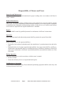
Responsibility of Owners and Users
Inspection and Maintenance
7KHGHYLFHVKDOOEHLQVSHFWHGDQGPDLQWDLQHGLQSURSHUZRUNLQJRUGHULQDFFRUGDQFHZLWK3UHVWR¶V
RZQHU¶VPDQXDO
Removal from Service
Any device not in safe operating condition such as, but not limited to, excessive leakage, missing
rollers, pins, or fasteners, any bent or cracked structural members, cut or frayed electric, hydraulic,
or pneumatic lines, damaged or malfunctioning controls or safety devices, etc. shall be removed from
VHUYLFHXQWLOLWLVUHSDLUHGWRWKHRULJLQDOPDQXIDFWXUHU¶VVWDQGDUGV
Repairs
$OOUHSDLUVVKDOOEHPDGHE\TXDOL¿HGSHUVRQQHOLQFRQIRUPDQFHZLWK3UHVWR¶VLQVWUXFWLRQV
Operators
Only trained personnel and authorized personnel shall be permitted to operate PowerStak.
Before Operation
%HIRUHXVLQJWKHGHYLFHWKHRSHUDWRUVKDOOKDYH
5HDGDQGRUKDGH[SODLQHGDQGXQGHUVWRRGWKHPDQXIDFWXUHU¶VRSHUDWLQJLQVWUXFWLRQVDQGVDIHW\
rules.
Inspected the device for proper operation and condition. Any suspect item shall be carefully exDPLQHGDQGDGHWHUPLQDWLRQPDGHE\DTXDOL¿HGSHUVRQDVWRZKHWKHULWFRQVWLWXWHVDKD]DUG$OO
LWHPVQRWLQFRQIRUPDQFHZLWK3UHVWR¶VVSHFL¿FDWLRQVKDOOEHFRUUHFWHGEHIRUHIXUWKHUXVHRIWKH
PowerStak.
During Operation
7KHGHYLFHVKDOORQO\EHXVHGLQDFFRUGDQFHZLWKWKLVRZQHU¶VPDQXDO
Do not overload.
Ensure that all safety devices are operational and in place.
0RGL¿FDWLRQVRU$OWHUDWLRQV
0RGL¿FDWLRQVRUDOWHUDWLRQVWRDQ\3UHVWRLQGXVWULDOSRVLWLRQLQJHTXLSPHQWVKDOOEHPDGHRQO\ZLWK
written permission from Presto.
OWNER’S MANUAL
Page 6
M100, M200, M300 & M400 FOOT OPERATED LIFTS
SECTION 2
SAFETY
The M Series stackers are very capable of causing serious injury or damage if adequate precautions are not
WDNHQ%\UHDGLQJDQGIROORZLQJWKLVPDQXDORSHUDWRU
injury may be prevented.
DO NOT INSTALL OR OPERATE THESE LIFTS
WITHOUT CAREFULLY READING THIS MANUAL. In order to provide for the safe operation of these
VWDFNHUV3UHVWR/LIWV,QFKDVLGHQWL¿HGFHUWDLQKD]DUGV
that may occur during the installation, maintenance and
use of these lifts.
WARNING!
Do not perform any repair work on lifts if there is
a load on the platform or forks are in the raised or
lowered position.
All personnel must stand clear of the lift when the
lift is in motion.
Do not put hands or feet under forks or platform
while in motion.
Do not put hands or feet on or near the mast
while the forks or platform is in motion.
Do not stand, sit or climb on the lift.
Do not exceed the load capacity.
Place all loads centrally located on the lift forks
or platform.
Do not place a load on a moving lift.
Do not use the lift on soft, uneven or unstable
surfaces.
Do not shock load the forks or platform. Materials must be carefully placed rather than dropped.
OWNER’S MANUAL
Page 7
M100, M200, M300 & M400 FOOT OPERATED LIFTS
SAFETY ALERT SYMBOLS AND SIGNAL WORDS
The safety of all persons operating, maintaining, repairing, or in the vicinity of this equipment is of paramount
concern. This is a powerful machine with moving parts, and is capable of causing personal injury if proper
SUHFDXWLRQVDUHQRWWDNHQ7KHUHIRUHWKURXJKRXWWKLVPDQXDOFHUWDLQKD]DUGVKDYHEHHQLGHQWL¿HGZKLFKPD\
occur in the use of the machine, and there are appropriate instructions or precautions which should be taken to
avoid these hazards. In some cases, there are consequences which may occur if instructions or precautions are
QRWIROORZHG%HORZDUHWKHV\PEROVDQGVLJQDOZRUGVDORQJZLWKWKHLUGH¿QLWLRQVUHIHUHQFHGIURP$16,=
- Product Safety Signs and Labels.
Safety Alert Symbols
These are the safety alert symbols.. They are used to alert you to potential physical injury hazards. Obey all safety messages that follow this symbol to avoid possible injury or death.
For use with DANGER signal word
5HG%DFNJURXQG
For use with WARNING signal word
2UDQJH%DFNJURXQG
For use with CAUTION signal word
<HOORZ%DFNJURXQG
Signal Words
7KHPHDQLQJRIGLIIHUHQWVLJQDOZRUGVDVGH¿QHGE\$16,6WDQGDUG=LQGLFDWHVWKHUHODWLYH
seriousness of the hazardous situation.
DANGER indicates a hazardous situation which, if not avoided,
will result in death or serious injury.
5HG%DFNJURXQG
WARNING indicates a hazardous situation which, if not avoided,
could result in death or serious injury.
2UDQJH%DFNJURXQG
<HOORZ%DFNJURXQG
CAUTION, used with the safety alert symbol, indicates a hazardous situation which, if not avoided, could result in minor or
moderate injury.
NOTICE is used to address practices not related to personal
injury.
%OXH%DFNJURXQG
SAFETY
INSTRUCTIONS
6$)(7<,16758&7,216RUHTXLYDOHQWVLJQVLQGLFDWHVDIHW\
related instructions or procedures.
*UHHQ%DFNJURXQG
OWNER’S MANUAL
Page 8
M100, M200, M300 & M400 FOOT OPERATED LIFTS
SECTION 3
7RORZHUOLIWSUHVVUHOHDVHSHGDOGRZQ3UHVVXUHRQ
release pedal controls speed of descent of load.
INSTALLATION
INSTALLATION
When the stacker arrives on a pallet the following steps
are to be followed:
1. Through the use of a forklift or overhead hoist, pick
the stacker unit up taking into consideration the center
of gravity. The center of gravity of the unit should be
adequately supported.
2QFHWKHXQLWLVOLIWHGIURPWKHSDOOHWE\DFRXSOHRI
inches, remove the pallet from under the stacker.
SECTION 5
MAINTENANCE
ROUTINE MAINTENANCE:
*UHDVHZKHHOVDQGFDVWHUVDWOHDVWRQFHDPRQWKWR
maintain easy roll of lift.
)ROORZWKHQH[WVHFWLRQVWRHQVXUHSURSHURSHUDWLRQ
'R QRW RYHUORDG WKH OLIW$OO IRRW RSHUDWHG 3UHVWR
Manual Stackers have a maximum rated capacity
RIOEV
SECTION 4
8VH RQO\ K\GUDXOLF RLO LQ WKH K\GUDXOLF V\VWHP
1(9(586(+<'5$8/,&%5$.()/8,'
OPERATION
METHOD OF OPERATION:
In order to operate the lift follow these operating procedures.
7RUDLVHWKHSODWIRUPRUIRUNVSXPSIRRWSHGDOXQWLO
platform reaches desired height.
7DEOH±+\GUDXOLF2LO6SHFL¿FDWLRQV
If the lift will be used at normal ambient temperatures, Presto Lifts supplies the unit with Conoco Super Hydraulic
32 oil. This may be replaced by any other good quality oil with 150 SSU at 100° F and rust and oxidation inhibitors
and anti-wear properties.
If the lift will be used at ambient temperatures below 0°F, use aircraft hydraulic oil. Use Type 15 aircraft hydraulic oil.
The following are equivalent to Conoco Super Hydraulic 32:
TYPE
MANUFACTURER
AW32 .......................................... CITGO
DTE 24 ....................................... EXXON/MOBIL
NUTO H32 ................................. EXXON/MOBIL
AMOCO AW32 ........................... CHEVRON (AMOCO CO.)
CAUTION!
It is very important to keep the hydraulic oil free of dirt, dust, metal chips, water, and other
contamination. Most of the problems with hydraulic systems are caused by contamination in the oil.
OWNER’S MANUAL
Page 9
M100, M200, M300 & M400 FOOT OPERATED LIFTS
SECTION 6
SECTION 7
SERVICE
TROUBLESHOOTING
To remove cylinder from lift:
3XPSOLIWWRDERYH
KHLJKWDQGWKHQSURSSODWform or forks up to keep it in raised position.
If lift does not rise to full height:
,WSUREDEO\UHTXLUHVRLO&KHFNZLWKOLIWLQGRZQ
SRVLWLRQ 7R ¿OO F\OLQGHU ZLWK RLO IROORZ WKHVH
instructions.
6WHS RQ UHOHDVH SHGDO DQG SXVK UDP GRZQ E\
hand until it reaches its lowest point.
6OLS FKDLQ RII SXOOH\ DQG UHPRYH SXOOH\ DVsembly.
7DNHRIIWZRERWWRPFDSVFUHZVWKDWKROGF\OLQder in place and slide cylinder forward towards the
base legs of the lift. The cylinder can now easily
be removed.
To replace ram chevron set in hydraulic cylinder
assembly:
1. Remove hydraulic cylinder from lift and remove
9HQW3OXJ3DUW1R0DQG2LO/HYHO3OXJ3DUW
1RDQGGUDLQRLOIURPF\OLQGHU
&ODPSSXPSERG\LQYLVHXQVFUHZWRSKH[QXW
and remove outer cylinder.
5HPRYHLQQHUF\OLQGHUIURPSXPSPDNLQJVXUH
not to distort or mar cylinder. Note: Do not use
pipe wrench.
5HPRYHUDPDQGUHSODFHFKHYURQVHW
There are two pipe plugs in the cylinder, Part No.
09HQW3OXJDQGSDUW1R02LO/HYHO
3OXJ5HPRYHERWKSOXJV
Put a good grade of hydraulic jack oil in the cylinder
through the top hole. When the oil reaches the level
of the bottom hole, replace both plugs. TOP PLUG
,6$%5($7+(53/8*%(685(725(3/$&(
PLUGS IN THEIR PROPER PLACES.
If lift does not hold load, or tends to drift downward under a load:
Dirt particle may be obstructing seating of the
valve, allowing leakage.
If dirt particle is obstructing seating of the
valve:
Open release valve by pressing down on release
pedal. At the same time, pump foot lever three or
four strokes. Do this three or four times. Then place
some weight on the platform or forks and pump foot
lever until platform reaches its full height. Now,
lower lift six inches to a foot at a time. This should
dislodge dirt and lift should work properly.
3XVK UDP LQWR LQQHU F\OLQGHU FKHYURQ HQG
last!
5HDVVHPEOH DQG ¿OO ZLWK FOHDQ K\GUDXOLF MDFN
oil.
OWNER’S MANUAL
Page 10
M100, M200, M300 & M400 FOOT OPERATED LIFTS
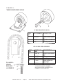
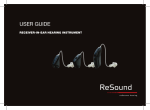
F I G U R E 1:
WHEEL IDENTIFICATION
WHEEL IDENTIFICATION
ITEM
NO.
1
PART NUMBER DESCRIPTION
C101PH2
2
3
C102PH
C103
Swivel Caster Assembly
Rigid Phenolic Wheel
Mounting Hardware
CHAIN ROLLER ASSEMBLY
F I G U R E 2:
CHAIN
ROLLER
ASSEMBLY
OWNER’S MANUAL
ITEM
NO.
1
PART NUMBER
0584-VR
2
3
4
C104**
C106B
C106C
5
C106A
DESCRIPTION
Single Chain Assembly
Chain
Lock Ring
Chain Socket 3/4''
Adjustable
Clevis Pin
63(&,),&02'(/180%(5
REQUIRED WHEN ORDERING FOR
CORRECT CHAIN LENGTH
Page 11
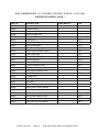
M100, M200, M300 & M400 FOOT OPERATED LIFTS
RECOMMENDED CYLINDER SPARE PARTS LISTING
M SERIES STACKERS - PAGE 1
PART #
M400**
M402
M403
M404
M407
M410
N1200
M412
M413
M414
M415
M416
M417
M419
M420
M422
M423
M424
M425
M426**
M427
N1200
M429
M430**
M431**
M432
M433-01
M434
DESCRIPTION
Hydrualic Cylinder Assy. Complete
Release Lever
Release Lever Pin
Pump Plunger Clip
N/A see 0457
Pump Body
Pump Body Plug
Pump Check Ball
Pump Check Spring
Pump Valve/Release Gaket
Pump Valve Bolt
Release Ball & Poppet
Release Spring
Release Bolt
O Ring Reservoir Seal
Pump Lever Bracket
Pump Lever Bracket Pins
Ram O Ring Seal
Cylinder Nut
Outer Cylinder
Vent Plug
Oil Lever Plug
Pump Lever Return Spring
Inner Cylinder
Ram
Ram Guide Bearing Plate
Ram Chevron Set
Ram Chevron Set Washer
OWNER’S MANUAL
Page 12
AVAILABILITY
A
A
A
K
K
A
K
K
A
K
K
K
K
K
A
A
K
A
N
A
A
A
N
N
K
A
K
KIT#
1&2
1&2
1&2
1&2
1&2
1&2
1&2
1&2
1&2
4&2
4&2
4&2
4&2
4&2
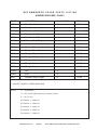
M100, M200, M300 & M400 FOOT OPERATED LIFTS
RECOMMENDED SPARE PARTS LISTING
M SERIES STACKERS - PAGE 2
PART #
DESCRIPTION
AVAILABILITY
KIT#
M435
Ram Cup Nut
K
4&2
M436
Foot Lever
A
M437
Foot Lever Pad
A
M438
Pump Intake Spring
K
1&2
M439
Pump Intake Ball
A
1&2
M440
Release Pin O Ring
K
5&2
M441
Release Pin Back-Up Ring
K
5&2
M442
Release Pin
K
5&2
M443
Plunger Sleeve Gasket
A
1-3 & 2
M444
Plunger Sleeve
K
1-3 & 2
M445
Plunger O Ring
A
1-3 & 2
M446
Plunger Nut
A
1-3 & 2
M447
Plunger Washer
A
1-3 & 2
M448
Plunger Cup
A
1-3 & 2
N0040
Nut
A
N0810
Bolt
A
0457
Square Pump Plunger
K
63(&,),&02'(/180%(55(48,5('
1-3 & 2
127(
$ $9$,/$%/(
1 127$9$,/$%/(0XVWEX\FRPSOHWH&\OLQGHU
K = In a kit only.
.LW1XPEHU 0
.LW1XPEHU 0
.LW1XPEHU 0
.LW1XPEHU 0
.LW1XPEHU 0
OWNER’S MANUAL
Page 13
M100, M200, M300 & M400 FOOT OPERATED LIFTS
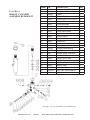
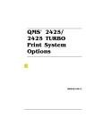
F I G U R E 3:
M400-10 PUMP BODY COMPLETE
Tip: Do not
VZDS
They are machined differently
Tip: Removal of #22,
#23, & #24 through #7
portal
P/N M400-10 Pump Body Complete includes all items below.
P/N M400-30 Pump Plunger Assembly includes items 13 thru 21.
P/N M400-50 Release Pin Assembly includes items 22 thru 24.
See pages 7 & 8 for availability of individual items.
ITEM
1R
1
2
3
4
5
6
7
8
9
10
11
12
13
PART
1R
M410
M420
M412
M416A
M417
M414
M419
M439
M438
M415
M413
M411
M443
QTY DESCRIPTION
1
1
2
1
1
2
1
1
1
1
1
1
1
Pump Body
Reservoir Seal O Ring
Pump Check Ball
Poppet
Release Spring
Gasket
Release Bolt
Pump Intake Ball
Pump Intake Spring
Pump Valve Bolt
Pump Check Spring
Plug
Gasket
OWNER’S MANUAL
Page 14
ITEM
1R
14
15
16
17
18
19
20
21
22
23
24
25
PART
1R
M444
M445
M446
M447
M448
M407A
M407B
0457
M442
M440
M441
M410-D
QTY DESCRIPTION
1
1
1
1
1
1
1
1
1
1
1
1
Plunger Sleeve
Plunger O Ring
Plunger Nut
Washer
Plunger Cup
Plunger Guide Brg.
Seal O Ring
Pump Plunger
Release Pin
Release Pin O Ring
Release Pin
Pin, Spring Roll
M100, M200, M300 & M400 FOOT OPERATED LIFTS
ITEM#
1
2
3
4
5
6
7
8
9
10
11
12
13
14
15
16
17
18
19
20
21
22
23
24
25
26
27
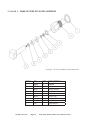
F I G U R E 4:
M400-20 CYLINDER
ASSEMBLY REPAIR KIT
P/N
M420
M412
M416A
M417
M414
M419
M439
M438
M415
M413
M443
M444
M445
M446
M447
M448
M407A
M407B
0457
M442
M440
M441
M435
M434
M433-01
M432-01
M424
DESCRIPTION
Reservoir Seal O Ring
Pump Check Ball
Poppet
Release Spring
Gasket 3/32 OD x 1/2 ID x 3/32 thk
Release Bolt
Pump Intake Ball
Pump Intake Spring
Pump Valve Bolt
Pump Check Spring
Gasket
Plunger Sleeve
Plunger O Ring
Plunger Nut
Washer
Plunger Cup
Plunger Guide Bearing
Seal O Ring
Plunger, Pump 1000/2000
Release Pin
Release Pin O Ring
Release Pin Back Up Ring (Split)
Nut, Ram Cup
Washer, Ram
Seal, Deep Z
Plate, Ram Guide Bearing
O Ring, Ram Seal, 813 ID x 1.06
See pages 7 & 8 for availability of individual items.
OWNER’S MANUAL
Page 15
M100, M200, M300 & M400 FOOT OPERATED LIFTS
4W\
1
2
1
1
2
1
1
1
1
1
1
1
1
1
1
1
1
1
1
1
1
1
1
1
1
1
1
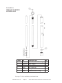
F I G U R E 5:
M400-30 PUMP PLUNGER ASSEMBLY
See pages 7 & 8 for availability of individual items.
ITEM #
1
2
P/N
M443
M444
QTY
1
1
DESCRIPTION
Gasket
6
7
8
9
0
0
0
0
0$
0%
1
1
1
1
1
1
1
Plunger O Ring
Plunger Nut
Washer
Plunger Cup
3OXQJHU*XLGH%HDULQJ
Seal O Ring
Pump Plunger
OWNER’S MANUAL
Page 16
Plunger Sleeve
M100, M200, M300 & M400 FOOT OPERATED LIFTS
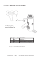
F I G U R E 6:
M400-40 CYLINDER
PACKING KIT
ITEM#
1
2
3
4
5
6
P/N
M432-01
M433-01
M434
M435
M424
M420
DESCRIPTION
Plate, Ram Guide Bearing
Seal, Deep Z
Washer, Ram
Nut, Ram Cup
O Ring, Ram Seal, 813 ID x 1.06
Reservoir Seal O Ring
4W\
1
1
1
1
1
1
See pages 7 & 8 for availability of individual items.
OWNER’S MANUAL
Page 17
M100, M200, M300 & M400 FOOT OPERATED LIFTS
F I G U R E 7:
M400-50 RELEASE PIN ASSEMBLY
1RWH6HH3DJHIRU
5HPRYDO,QVWDOODWLRQ7LSV
ITEM#
1
2
3
P/N
M442
M440
M441
QTY
1
1
1
DESCRIPTION
Release Pin
Release Pin O Ring
Release Pin Back Up Ring (Split)
See pages 7 & 8 for availability of individual items.
OWNER’S MANUAL
Page 18
M100, M200, M300 & M400 FOOT OPERATED LIFTS
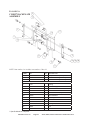
F I G U R E 8:
C118B27 BACKPLATE
ASSEMBLY
NOTE: Item number 1-A includes item numbers 2 thru 10
ITEM#
P/N
QTY
DESCRIPTION
1-A
C118B27-1000AVR
1
Backplate Assembly Complete 1000#
3
C111VR
1
Side Thrust Bearing Assembly R/S
4
C112VR
1
Side Thrust Bearing Assembly L/S
Item Numbers 3 & 4 Include Item Number 14
5
C107
4
Bearing
6
C108
4
Hood Bearing Spacer
7
N0427
4
5/8 Internal Lockwasher
8
N0180
4
5/8-16 Hex Nut
9
N0920
4
3/8-16 X 1'' Screw, Cap HH CR2
10
N0260
4
3/8 Lockwasher
11
C106B
2
Lock Rings
12
C106A
1
Clevis Pin
13
C104-XX**
1
Lift Chain
14
C114
8
Bearing
15
N0961
4
Bolt
16
N0260
4
Washer
6SHFL¿F0RGHO1R5HTXLUHG
OWNER’S MANUAL
Page 19
M100, M200, M300 & M400 FOOT OPERATED LIFTS
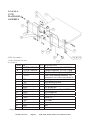
F I G U R E 9:
C117E
PLATFORM
ASSEMBLY
NOTE: Item numbers
1-A thru -B include item numbers 2 thru 10
ITEM#
1-A
-B
3
4
P/N
C117E24-1000AVR
C117E32-1000AVR
C111VR
C112VR
QTY
1
1
1
1
DESCRIPTION
Platform Assembly 24 X 24'' 1000#
Platform Assembly 32 X 30'' 1000#
Side Thrust Bearing Assembly R/S
Side Thrust Bearing Assembly L/S
Item Numbers 3 & 4 include Item Number 14
5
6
7
8
9
10
11
12
13
14
15
16
C107
C108
N0427
N0180
N0920
N0260
C106B
C106A
C104**
C114
N0961
N0260
4
4
4
4
4
4
2
1
1
8
4
4
Bearing
Hood Bearing Spacer
5/8 Internal Lockwasher
5/8-18 Hex Nut
3/8-16 X 1'' Screw, Cap HH CR2
3/8 Lockwasher
3/8 Lock Rings
Clevis Pin
Lift Chain
Bearing
Bolt
Washer
6SHFLIFPRGHOQXPEHUUHTXLUHG
OWNER’S MANUAL
Page 20
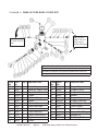
M100, M200, M300 & M400 FOOT OPERATED LIFTS
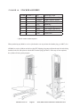
F I G U R E 10:
STACKER ASSEMBLY
ITEM#
1
2
3
4
5
6
7
8
QUANTITY
1
2
1
4
1
1
2
1
P/N
0584-VR
C102PH
M400**
C107
M429
M436
C101PH2
C100
DESCRIPTION
Chain Roller Assembly
Rigid Phenolic Wheel
Cylinder Assembly
Roller Kit
Return Spring
Foot Lever (pad M437)
Swivel Wheel Assembly
Floor Lock
6SHFLIFPRGHOQXPEHUUHTXLUHG
:KHQSXUFKDVLQJDQ\0[[VHULHVF\OLQGHUPDNHVXUHWRSXUFKDVHWKHEUHDWKHUSOXJSQ0DOVR
$OO0[[VHULHVF\OLQGHUVQHHGWRKDYHWKH137VKLSSLQJSOXJUHPRYHGIURPWKHWRSKROHDIWHUEHLQJ
LQVWDOOHGLQWKHOLIWDQGUHSODFHGZLWKWKH137EUHDWKHUSOXJSQ0,IWKLVVWHSLVQRWFRPSOHWHG
the cylinder will not operate properly.
OWNER’S MANUAL
Page 21
M100, M200, M300 & M400 FOOT OPERATED LIFTS
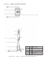
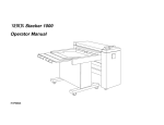
F I G U R E 11:
LABEL PLACEMENT DIAGRAM
ITEM #
1
6
7
OWNER’S MANUAL
Page 22
QTY
1
1
1
1
1
1
DESCRIPTION
Lock Up-Lock Down
Name Plate
Do Not Stand On Forks
3UHVWR/LIWV9HUWLFOH/RJR
Load Center
Help Line
M100, M200, M300 & M400 FOOT OPERATED LIFTS
PARTS
6WDQGDUGSDUWVPD\EHUHWXUQHGZLWKDUHVWRFNLQJIHHRUQHWZKLFKHYHU
LVJUHDWHU0RGL¿HGRUFXVWRPHQJLQHHUHGSDUWVDUHQRWUHWXUQDEOH8QIRUWXQDWHO\
GXHWRSRWHQWLDOO\FRQFHDOHGGDPDJHDOOVDOHVRIHOHFWULFDODVVHPEOLHVDUH¿QDO
QUALITY ISSUES
Should you feel there is a quality problem, please contact the seller to ask questions and gather information on how to rectify the issue. Presto Lift Inc. reserves
the right to determine potential credits, as a result of factory defects, based on its
inspection of the merchandise.
GENERAL
All products shipped from our factory have passed Quality Assurance inspection and
testing. The carrier of choice has signed for, and accepted the product in new working
condition. The customer should inspect to ensure it is not received damaged, has no
concealed damage or is not incomplete. Parts orders are determined to be complete
based upon Presto Lift, Inc. inspection sheets and carrier shipping weights.
OWNER’S MANUAL
Page 23
M100, M200, M300 & M400 FOOT OPERATED LIFTS
RETURN MATERIALS AUTHORIZATION POLICY
3UHVWR/LIWVSURYLGHVWKH5HWXUQ0DWHULDOV$XWKRUL]DWLRQ50$3ROLF\IRUVSHFL¿FPRGHOVDVD
courtesy to our distributors in the event they do not receive what they ordered. If a customer wishes
to return a Presto Lifts product, please contact the Customer Service Department and request an
50$QXPEHU7KLVUHTXHVWPXVWEHPDGHRQRUEHIRUHWKH¿IWHHQWKFDOHQGDUGD\IROORZLQJWKH
GDWHRI3UHVWR/LIWV¶LQYRLFHIRUWKHPHUFKDQGLVH1RWDOOXQLWVDUHUHWXUQDEOH4XDQWLW\RUGHUVDQG
special designs cannot be returned under any circumstances. Presto Customer Service reserves the
ULJKWIRU¿QDOMXGJPHQWRQDOOSURGXFWUHWXUQV
The RMA number must appear on the outside of any packaging material for a return to be accepted
and processed by Presto Lifts. Customers shipping returns from the Continental US, Canada, or
0H[LFRKDYHWKLUW\GD\VIURPGDWHRI50$LVVXHWRKDYHWKHSURGXFWDUULYHDW3UHVWR/LIWV
IDFLOLW\$OOPHUFKDQGLVHPXVWDUULYH)UHHRQ%RDUGDW3UHVWR/LIWV¶IDFLOLW\RUWKHVKLSPHQWZLOOEH
refused and returned to the sender. All credits are issued less restocking and refurbishing charges,
regardless if the merchandise was damaged in transit.
Return addresses: please refer to your RMA for the address to which your product should be returned.
Presto Lift Inc.
+LJKZD\
0DQLOD$UNDQVDV
7HOHSKRQH
)D[
OWNER’S MANUAL
Page 24
M100, M200, M300 & M400 FOOT OPERATED LIFTS
Ordering Replacement Parts
Presto Lifts has carefully chosen the components in your unit to be the best available for the purpose. Replacement
parts should be identical to the original equipment. Presto Lifts will not be responsible for equipment failures
UHVXOWLQJIURPWKHXVHRILQFRUUHFWUHSODFHPHQWSDUWVRUIURPXQDXWKRUL]HGPRGL¿FDWLRQVWRWKHXQLW
Presto Lifts can supply all replacement parts for your lift. With your order, please include the model number
DQGWKHVHULDOQXPEHURIWKHXQLW<RXFDQ¿QGWKHVHQXPEHUVRQWKHQDPHSODWH7KLVSODWHLVORFDWHGRQWKH
angle support at the top of the cylinder.
To order replacement parts, please call the Presto Parts Department. Parts are shipped subject to the following
terms:
)2%IDFWRU\
5HWXUQVRQO\ZLWKWKHDSSURYDORIRXU3DUWV'HSDUWPHQW
&UHGLWFDUGVSUHIHUUHGH[FHSWSDUWVFRYHUHGE\ZDUUDQW\
)UHLJKWFROOHFWIRUWUXFNH[FHSWSDUWVFRYHUHGE\ZDUUDQW\
)UHLJKWSUHSDLGDQGLQYRLFHIRUVPDOOSDUFHOVKLSPHQWVH[FHSWSDUWVFRYHUHGE\ZDUUDQW\
Parts replaced under warranty are on a “charge-credit” basis. We will invoice you when we ship the replacement
part, then credit you when you return the worn or damaged part, and we verify that it is covered by our warranty.
Labor is not covered under warranty for Parts orders.
Presto Parts Department
&RPPHUFH:D\
1RUWRQ0$
7HOHSKRQH
)$;
Email: [email protected]
www.PrestoLifts.com
OWNER’S MANUAL
Page 25
M100, M200, M300 & M400 FOOT OPERATED LIFTS
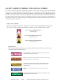
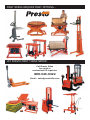
MANY NEEDS REQUIRE MANY OPTIONS...
LET PRESTO MEET THOSE NEEDS!
Call Presto Sales
for stock or
customized lift inquiries:
800-343-9322
Email: [email protected]