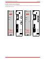
1
HDT‐4611 & HDR‐4611 Instruction Book
Revision 2
I R T Electronics Pty Ltd A.B.N. 35 000 832 575
26 Hotham Parade, ARTARMON N.S.W. 2064 AUSTRALIA
National: Phone: (02) 9439 3744
Fax: (02) 9439 7439
International:
+61 2 9439 3744
+61 2 9439 7439
Email: [email protected]
Web: www.irtelectronics.com
IRT Eurocard
Type HDT‐4611 & HDR‐4611
1.485 Gb/s HD & 270 Mb/s ASI / SDI Fibre Optic Link
DANGER
Invisible LASER radiationAvoid direct exposure to beam
Peak power
Wavelength
2 mW
1310–1610nm
Class 1 LASER Product
Designed and manufactured in Australia
IRT can be found on the Internet at:
http://www.irtelectronics.com
www.irtelectronics.com
Page 1 of 16
4611‐HDT_4611‐HDR_ib_Rev2.doc
HDT‐4611 & HDR‐4611 Instruction Book
Revision 2
IRT Eurocard
Type HDT‐4611 & HDR‐4611
1.485 Gb/s HD & 270 Mb/s ASI / SDI Fibre Optic Link
Revision History
Revision
0
1
Date
08/07/2008
29/10/2010
By
AL
AL
2
04/05/2011
AL
www.irtelectronics.com
Change Description
Original Issue.
Pictorial link diagrams added to link settings.
SNMP descriptors expanded upon.
Pathalogical test terminology (RP‐198) and
specifications corrected.
Page 2 of 16
Applicable to:
S/N ≥ 0804001
S/N ≥ 0804001
S/N ≥ 0804001
4611‐HDT_4611‐HDR_ib_Rev2.doc
HDT‐4611 & HDR‐4611 Instruction Book
Revision 2
IRT Eurocard
Type HDT‐4611 & HDR‐4611
1.485 Gb/s HD & 270 Mb/s ASI / SDI Fibre Optic Link
Instruction Book
Table of Contents
Section
Page
Revision History
Operational Safety
General Description
Technical Specifications
Configuration
Installation
Front and rear layouts
Operation
SNMP – What Is It?
HDT‐4611 & HDR‐4611 SNMP Functions
Maintenance & Storage
Warranty & Service
Equipment return
Drawing List Index
2
4
5
6
7
8
9
10
11
13
15
15
15
16
This instruction book applies to units later than S/N 0804001.
www.irtelectronics.com
Page 3 of 16
4611‐HDT_4611‐HDR_ib_Rev2.doc
HDT‐4611 & HDR‐4611 Instruction Book
Revision 2
Operational Safety:
WARNING
Operation of electronic equipment involves the use of voltages and currents that
may be dangerous to human life. Note that under certain conditions dangerous
potentials may exist in some circuits when power controls are in the OFF position.
Maintenance personnel should observe all safety regulations.
Do not make any adjustments inside equipment with power ON unless proper
precautions are observed. All internal adjustments should only be made by suitably
qualified personnel. All operational adjustments are available externally without
the need for removing covers or use of extender cards.
Optical Safety
The light emitted from the LASER diode used in this system is
invisible and may be harmful to the human eye. Avoid looking
directly into the fibre optic cable or connectors or into the
collimated beam along their axis when the device is in operation.
Operating the LASER diode outside of its maximum ratings may
cause device failure or a safety hazard.
DANGER
Invisible LASER radiationAvoid direct exposure to beam
Peak power
Wavelength
2 mW
1310–1610nm
Class 1 LASER Product
www.irtelectronics.com
Page 4 of 16
4611‐HDT_4611‐HDR_ib_Rev2.doc
HDT‐4611 & HDR‐4611 Instruction Book
Revision 2
IRT Eurocard
Type HDT‐4611 & HDR‐4611
1.485 Gb/s HD & 270 Mb/s ASI / SDI Fibre Optic Link
General Description
HDT-4611 / HDR-4611 Block Diagram
HDT-4611
1.485Gb/s HD
ASI/SDI
I/P Monitor
HDR-4611
Monitor O/P
Fibre O/P
SNMP
Fibre Link
5-31dB path loss
Alarm O/P
O/P 1
O/P 2
Fibre I/P
1.485Gb/s HD
ASI/SDI
SNMP
Alarm O/P
The IRT HDT‐4611 and HDR‐4611 are transmit and receive modules designed principally for use as a SMPTE292M
1.485 Gb/s serial digital video Fibre Optic transmission link, using 9/125 single mode fibre for path lengths with
path attenuation of 5‐31 dB. This enables the use of space saving fibre optic cable for reliable transmission of
digital video signals over lengths greater than can be provided with coaxial cable. The transmit / receive system
specifications apply to all signal conditions, including the SMPTE RP‐198 pathological test sequence.
The HDT‐4611 transmitter features an input circuit with automatic cable equalisation for Belden 8281 (or
equivalent) coaxial cable followed by a plug‐in LASER transmitter. A monitor output is provided on the rear
assembly.
The HDR‐4611 receiver uses a plug‐in APD detector preamplifier module, signal conditioning and a reclocking
circuit for the 1.485 Gb/s data rate, or for 270 Mb/s SDI and ASI signals. Two non‐inverted serial digital outputs are
provided from the transmission link on the rear assembly.
On the HDT‐4611 transmitter LED indicators on the front panel indicate the presence of signal, loss of laser power
and presence of DC power. Relay contact outputs for remote indication will indicate failure of the laser operation,
loss of input signal, and loss of power.
On the HDR‐4611 receiver LED indicators on the front panel indicate PLL lock at 1.485Gb/s or 270 Mb/s operation,
locked signal presence, optical input failure, and presence of DC power. Relay contact outputs for remote
indication will indicate loss of signal, loss of optical input, and loss of power.
An optional SNMP (Simple Network Management Protocol) plug‐in module is available, for each unit, for remote
monitoring when used in conjunction with an IRT frame fitted with SNMP capability.
The HDT‐4611 and HDR‐4611 are Eurocard modules designed to fit IRT’s standard range of Eurocard frames1 and
may be used alongside any other of IRT’s analogue or digital Eurocards.
Standard features:
•
•
•
•
•
•
One type covers 1.485 Gb/s High Definition or 270 Mb/s data signals.
Work reliably over 5 ‐ 31dB optical path range using 9/125 m single mode fibre.
Passes SMPTE RP‐198 pathological test sequence at 1.485 Gb/s and 270 Mb/s data.
LED indicators and external alarm contacts.
Fibre, video and alarm connections at rear.
Optional plug‐in SNMP monitoring module.
Applications:
•
•
Transmission of 1.485 Gb/s signals over distances > 100 meters.
Eliminates ground loop problems.
NOTE: 1 For use with 1.485 Gb/s HD signals it is recommended that these modules be housed within an
IRT 1RU or 4000 series 3RU frame only.
www.irtelectronics.com
Page 5 of 16
4611‐HDT_4611‐HDR_ib_Rev2.doc
HDT‐4611 & HDR‐4611 Instruction Book
Revision 2
Technical Specifications
HDT‐4611 ‐ Transmitter
Input impedance
Input return loss
Input serial data signal
Equalisation
Input Connector
Monitor Connector
75 Ω.
>15 dB 5 MHz to 1.5 GHz,
SMPTE/EBU 1.485 Gb/s or 270 Mb/s serial data (SDI or ASI).
Automatic, up to 100 metres at 1.485 Gb/s , and up to 250 metres at 270 Mb/s,
for Belden 8281 or equivalent cable.
1, BNC on rear assembly.
1, BNC on rear assembly.
HDR‐4611 ‐ Receiver
Number of outputs
Output level
Output impedance
Output return loss
Output rise/fall time
Intrinsic system jitter
Output Connector
2 data reclocked, AC coupled.
800 mV ± 10% into 75 Ω.
75 Ω.
>15 dB 5 MHz to 1.5 GHz.
<200 ps at 1.485 Gb/s, >400 ps & <1.5 ns at 270 Mb/s.
<0.2 UI at 1.485 Gb/s reclocked,
<0.1 UI at 270 Mb/s reclocked.
2, BNC on rear assembly.
Optical
Optical path loss2
Optical fibre
Optical wavelength (standard)
Spectral width
Optical connectors
HDT‐4611 optical output
HDR‐4611 optical input2
5 ‐ 31 dB.
Designed for use with 9/125 single mode fibre.
1310 nm ± 30 nm.
3 nm typically.
SC/PC on bracket attached to module.
0 dBm +0, ‐1 dB.
‐31 dBm min, ‐5 dBm max.
Alarm/Control connections
Phoenix 4 pin terminal plug in block.
Three relays energised in the normal condition to indicate loss of DC power,
signal or laser power on the HDT‐4611, or optical input low on the HDR‐4611.
Relay circuits are wired with contacts normally closed (or open) as set by a link on
the circuit board.
Alarm outputs
Power requirement:
Voltage
Consumption
28 Vac CT (14‐0‐14 Vac) or ±16 Vdc.
HDT‐4611 2.6 VA (90 mA), HDR‐4611 3.7 VA (130 mA).
General:
Operating temperature
Mechanical
Size
Weight
Finish
Front panel
Rear assembly
Standard accessories
Optional accessories
NOTE:
2
0 to 50° C ambient.
Suitable for mounting in IRT 19" rack chassis with input, output and power
connections to the rear.
For use with 1.485 Gb/s HD signals it is recommended that these modules be
housed within an IRT 1RU or 4000 series 3RU frame only.
6 HP x 3 RU Extended Eurocard (220 mm x 100 mm).
HDT‐4611: 405g, HDR‐4611: 410g (with rear assembly)
Grey background, black lettering & red IRT logo.
Detachable PCB with connectors to Eurocard and external signals.
Rear connector panel (supplied with module).
SMU‐4000 SNMP plug in module for use with IRT frame fitted with SNMP
“Agent”.
5 or 10dB optical attenuator must be used for HDR‐4611 when optical path loss is
less than 5dB.
Due to our policy of continuing development, these specifications are subject to change without notice.
www.irtelectronics.com
Page 6 of 16
4611‐HDT_4611‐HDR_ib_Rev2.doc
HDT‐4611 & HDR‐4611 Instruction Book
Revision 2
Configuration
Other than the following link settings, there are no user configurable settings. All other potentiometer and link
settings are factory set and should not be moved.
User link settings:
HDT‐4611:
LK1
1
2
3
1‐2
2‐3
Signal Loss alarm relay switched to ground on loss of input signal.
(Default position).
Signal Loss alarm relay switched to ground with input signal present.
1
2
3
LK2
1‐2
2‐3
Laser Fail/Off alarm relay switched to ground when laser is ok and on.
Laser Fail/Off alarm relay switched to ground when laser fails or is switched off.
(Default position).
1
2
3
LK3
1‐2
Power Fail alarm relay switched to ground when +5Vdc power rail fails.
(Default position).
Power Fail alarm relay switched to ground when +5Vdc power rail ok.
2‐3
3 2 1
SD HD
LK4
2‐3
Enable Laser ‐ laser is always enabled: ‘keep link alive’ signal when no input
signal is present. (Default position).
Auto Laser – laser is enabled only when an input signal is present.
LK53
1‐2
2‐3
HD slew rate – adjust Output Monitor slew rate to be optimised for HD.
SD slew rate – adjust Output Monitor slew rate to be optimised for SD.
LK64
IN
Reduces the input equalisation sensitivity for 270MB SD signals for use in
noisy environments or when a short input cable is used.
Input equalisation for 270Mb SD signals at maximum sensitivity.
(3 2 1)
1‐2
OUT
NOTE: 3 With link 5 in the wrong position to the actual input signal type, the monitoring output will not
meet SMPTE specification. This slew rate setting does not affect the signal transmitted via the
fibre output.
4 Link 6 not fitted to PCB.
HDR‐4611:
LK1
1
2
3
1
2
3
1
2
3
1‐2
2‐3
Signal Loss alarm relay switched to ground on loss of input signal.
(Default position).
Signal Loss alarm relay switched to ground with input signal present.
LK2
1‐2
2‐3
Optical Input Low alarm relay switched to ground when optical input is ok.
Optical Input Low alarm relay switched to ground when getting close to, or
exceeding, maximum optical path loss. Set to come on at approximately
‐28dBm optical input power. (Default position).
LK3
1‐2
Power Fail alarm relay switched to ground when +5Vdc power rail fails.
(Default position).
Power Fail alarm relay switched to ground when +5Vdc power rail ok.
www.irtelectronics.com
2‐3
Page 7 of 16
4611‐HDT_4611‐HDR_ib_Rev2.doc
HDT‐4611 & HDR‐4611 Instruction Book
Revision 2
Installation
Pre‐installation:
Handling:
This equipment may contain or be connected to static sensitive devices and proper static free handling
precautions should be observed.
Where individual circuit cards are stored, they should be placed in antistatic bags. Proper antistatic procedures
should be followed when inserting or removing cards from these bags.
Power:
AC mains supply:
Ensure that operating voltage of unit and local supply voltage match and that correct rating
fuse is installed for local supply.
DC supply:
Ensure that the correct polarity is observed and that DC supply voltage is maintained within
the operating range specified.
Earthing:
The earth path is dependent on the type of frame selected. In every case particular care should be taken to ensure
that the frame is connected to earth for safety reasons. See frame manual for details.
Signal earth: For safety reasons a connection is made between signal earth and chassis earth. No attempt should
be made to break this connection.
Installation in frame or chassis:
See details in separate manual for selected frame type.
Signal connections:
The HDT‐4611 and HDR‐4611 are set up to operate at either 1.485 Gb/s HD or 270 Mb/s SD signals and do not
require any adjustment prior to use, with the exception of a slew rate link setting for HD or SD on the monitoring
output of the HDT‐4611. There are no external controls on the front panel of the units.
Optical connections are made to the panel adapter mounted on a bracket at the rear of the modules. Care must
be taken to provide a clean surface on the optical connectors and in inserting the plug on the external fibre to
prevent damage to the alignment ferrule of the panel adapter. Type of fibre used must be single mode type.
The serial digital signal connections are made to the BNC connectors on the rear panel.
The external alarm contact connections are made to the 4 pin parallel wired connectors at the bottom of the rear
panel.
The connections are:
HDT‐4611
SK4/4A
pin 4
pin 3
pin 2
pin 1
dc power fail
laser fail/laser off
digital signal loss
ground
HDR‐4611
SK5/6
pin 4
pin 3
pin 2
pin 1
dc power fail
optical low/optical loss
digital signal loss
ground
The presence of the internal DC supply voltage is indicated by the front panel DC LED (green).
www.irtelectronics.com
Page 8 of 16
4611‐HDT_4611‐HDR_ib_Rev2.doc
HDT‐4611 & HDR‐4611 Instruction Book
Revision 2
Front & rear panel connector diagrams
The following front panel and rear assembly drawings are not to scale and are intended to show connection order
and approximate layout only.
HD F.O. TX
H DT -4 6 1 1
HD F.O. RX
H DR -4 6 1 1
P3
P3
INPUT
SK1
OUTPUTS
SK1
SIGNAL
LOCKED
SIGNAL
LASER
INPUT
FAIL
MONITOR
OUTPUT
SK2
SD
SK2
HD
SK5
SK4A
4
4
3
3
2
2
1
1
4
DC
3
CAUTION
Direct
connections
to module
2
1
SK4
4
SK4-SK4A
ALARM
CONTACTS
4-POWER
3-OPTICAL
2-SIGNAL
1-GROUND
DC
3
2
CAUTION
Direct
connections
to module
1
SK6
P2
N140
www.irtelectronics.com
SK5-SK6
ALARM
CONTACTS
4-POWER
3-OPTICAL
2-SIGNAL
1-GROUND
P2
N140
Page 9 of 16
4611‐HDT_4611‐HDR_ib_Rev2.doc
HDT‐4611 & HDR‐4611 Instruction Book
Revision 2
Operation
The HDT‐4611 and HDR‐4611 are set up to operate at either 1.485 Gb/s HD or 270 Mb/s SD and do not require
any adjustment prior to use. There are no external controls on the front panel of the units.
A 1.485 Gb/s HD signal or a 270 Mb/s type of signal, such as ASI or SDI, is connected to a 75 BNC connector on
the rear assembly of the HDT‐4611 fibre optic transmitter. A front panel LED, and a relay alarm accessible by the
rear assembly, indicates the presence of a valid input signal. Likewise, front panel LEDs, and a relay alarm also
accessible by the rear assembly, indicates when the laser module is ON or either fails or is automatically turned off
on loss of input signal. Link settings set whether the laser is permanently enabled or only enabled whilst a valid
input signal is present.
If the laser is set for permanent operation, on loss of an input signal, a 54MHz oscillator is switched into the optical
output so that the HDR‐4611 still recognizes the optical link as being valid. This 54MHz signal does not affect the
signal reclocking detect circuitry of the HDR‐4611, which is used in signal presence/alarm indication on detection
or absence of a valid HD or SD signal.
A monitor output is available via a 75 BNC connector on the rear assembly. Link LK5 sets the slew rate for either
SD or HD on the monitor output. This slew rate setting does not affect the signal transmitted via the fibre output.
With an optical laser sub‐board fitted to the transmitter, single mode optical cable is directly connected to the
module at the rear of the unit. Likewise the fibre connection at the far end of the fibre optic cable is directly
connected to the rear of the receiver.
The system will operate with an optical path loss from 5dB to a maximum of 31dB. For path lengths <5dB optical
loss, an optical attenuator is recommended. The length of fibre that this corresponds to depends on the fibre loss
characteristics at the relevant wavelength of the laser module chosen. For example, if the fibre loss characteristic
of the chosen fibre is 0.3dB per kilometre at 1310 nm, say, and assuming 1 dB for various in line connector losses,
then the maximum distance that can be run is 100 km ((31dB‐1dB)/0.3dBkm‐1).
The HDR‐4611 receiver module accepts an input optical signal with a power level in the range of ‐5 dBm to
‐31 dBm. A red LED ‘Optical Fail’ indicator on the front panel, and a relay alarm accessible by the rear assembly,
indicates when the optical path loss has exceeded the maximum 31 dB allowed.
The output of the HDR‐4611 receiver is the same signal that was originally inputted to the HDT‐4611 transmitter. A
front panel green LED, and a relay alarm accessible by the rear assembly, indicates the presence of a valid locked
output signal. Another green LED indicates whether the received signal is an HD type of signal, or a yellow LED
indicates whether the received signal is an SD type of signal.
www.irtelectronics.com
Page 10 of 16
4611‐HDT_4611‐HDR_ib_Rev2.doc
HDT‐4611 & HDR‐4611 Instruction Book
Revision 2
SNMP
What Is It?
SNMP stands for Simple Network Management Protocol. It is an application layer protocol for managing IP
(Internet Protocol) based systems. SNMP enables system administrators to manage system performance, and to
find and solve system problems. SNMP runs over UDP (User Datagram Protocol), which in turn runs over IP.
Three types of SNMP exist: SNMP version 1 (SNMPv1), SNMP version 2 (SNMPv2) and SNMP version 3 (SNMPv3).
It is not the intention here to discuss the differences between various versions, only to bring attention to the fact
that IRT Electronics modules, fitted with SNMP capability, use SNMPv1.
An SNMP managed network consists of three key components: Network Management Systems (NMS), agents, and
managed devices.
An NMS is the console through which the network administrator performs network management functions, such
as monitoring status (e.g. alarm states) and remote controlling, of a set of managed devices. One or more NMSs
must exist on any managed network. Generally the NMS is a computer running third party SNMP control software.
There are a number of third party SNMP software applications currently available on the market.
An NMS polls, or communicates with, an agent. An agent is a network management software module that resides
in a managed device. An agent has local knowledge of management information and translates that information
into a form compatible with SNMP. The agent, therefore, acts as an interface between the NMS and the managed
devices. The NMS sends a request message, and control commands for the managed devices, to the agent, which
in turn sends a response message, containing information about the managed devices, back to the NMS.
A managed device contains an SNMP agent and resides on a managed network. Managed devices collect and store
management information and make this information available to NMSs using SNMP.
Managed device agent variables are organised in a tree structure known as a Management Information Base
(MIB). Within the MIB are parameters pertaining to the managed device. An Object Identifier (OID) number within
the MIB defines the managed device type. This is a unique number specific to the model of managed device. Other
information relating to the device is also stored, information such as alarm states, controllable settings, etc. The
MIB tree is organised in such a way that there will be no two MIB files with conflicting placements.
Normally an NMS polls an agent for information relating to the MIB in a managed device to be sent back to the
NMS. When certain conditions are met within the MIB, such as major alarm conditions, for example, the agent
automatically sends what is known as a trap to the NMS without any prompting from the NMS. This allows
automatic notification of a predetermined event.
SNMP Block Diagram
NMS
IP
Network
NMS
www.irtelectronics.com
Page 11 of 16
SNMP Agent
Protocol Engine
MIB
SNMP Agent
SNMP Agent
Protocol Engine
MIB
SNMP Agent
SNMP Agent
Protocol Engine
MIB
SNMP Agent
4611‐HDT_4611‐HDR_ib_Rev2.doc
HDT‐4611 & HDR‐4611 Instruction Book
Revision 2
SNMP with IRT Products:
IRT Electronics currently employs SNMPv1 with its SNMP capable frames. The frame acts as an agent when fitted
with a CDM‐xxxx module. This module has its own designated slot next to the power supply so as to not affect the
number of modules that the frame will take. Communication between the NMS, the frame and its loaded modules
are via this CDM‐xxxx module. Note that the NMS software is third party and not supplied by IRT Electronics.
Ethernet connection for SNMP operation is via an RJ45 connector on the rear of the frame, below the mains inlet.
Ethernet rate runs at either 10 baseT or 100 baseT.
Frame parameters, such as Name, Address and Location, are set via an RS232 interface, a D9 connector on the
rear of the frame below the mains inlet. A software terminal emulator, such as Tera Term or HyperTerminal, is
used for setting and reading the parameters of the frame.
IRT modules that are SNMP compatible need a plug‐in SMU‐4000 module with a program relevant to the module
that it is plugged into. Depending on the module, besides the module identification, parameters such as alarm
states, inputs and controls etc. are communicated to the CDM‐xxxx agent via a data bus on the rear of the frame.
Thus the CDM‐xxxx collects information on what is loaded within the frame, what positions they occupy, and their
current status for communication to the NMS when the NMS sends a request for information.
In the event of a major alarm from any of the SNMP compatible modules, or power supplies, a trap is
automatically sent by the CDM‐xxxx agent to the NMS without any prompting by the NMS. This alerts the operator
to any fault conditions that may exist that need immediate attention.
110/240 V 50/60 Hz
0.7 A (max.)
FRU-4000
FRAME
FUSES
220/240 Vac
500 mA S.B.
110/120 Vac
1A S.B.
RS232
Alarm
Ethernet
+
48Vdc
AS3260 approval no.: CS6346N
Ass. no.: 804692
IRT SNMP Connections
IRT modules fitted
with SMU-4000
NMS
IP
Ethernet Cable
Network
CDM-xxxx
PSU’s
IRT SNMP Frame
Ethernet Cable
IRT modules fitted
with SMU-4000
CDM-xxxx
PSU’s
IRT SNMP Frame
Ethernet Cable
IRT SNMP Setup
www.irtelectronics.com
Page 12 of 16
4611‐HDT_4611‐HDR_ib_Rev2.doc
HDT‐4611 & HDR‐4611 Instruction Book
Revision 2
HDT‐4611 & HDR‐4611 SNMP Functions:
With the HDT‐4611/HDR‐4611 fitted with the optional plug‐in SMU‐4000 SNMP module, programmed with the
firmware to suit and installed in an IRT frame with SNMP capability, these can be interrogated by an SNMP
Network Management System (NMS). The HDT‐4611 and HDR‐4611 share the same MIB so same object identifier
name means different things, or may not be applicable, when comparing between the two cards.
The following SNMP functions are capable of being monitored by an NMS:
HDT‐4611:
irt4611Signal
irt4611Optical
An indication that an input signal is present:
(1) notPresent – no valid input signal is present.
(2) present – valid input signal is present.
An indication that there is an output from the Laser:
(1) OpticalSignalPresent – output from laser is present.
(2) noOpticalSignal – no output from laser.
irt4611OpticalConfig An indication of the Laser wavelength:
(1) nm1470 – 1470nm.
(2) nm1490 – 1490nm.
(3) nm1510 – 1510nm.
(4) nm1530 – 1530nm.
(5) nm1550 – 1550nm.
(6) nm1570 – 1570nm.
(7) nm1590 – 1590nm.
(8) nm1610 – 1610nm.
(15) nm1310 – 1310nm.
irt4611FactoryLevel
Factory use only. Not Applicable.
irt4611LaserEnable
An indication of the state of the laser enable control, as well as being able to enable via
SNMP:
(1) enabled.
(2) snmpEnabled.
(3) notEnabled.
NOTE: Dependent upon Laser Enable (LK4) setting.
irt4611Reset
Unit reset control. A set with a value of 2 sent to this OID will cause a system reset to
occur.
irt4611AlarmSource
Set and read conditions that may send a Trap when an alarm occurs and when it clear:
(1) optical – Trap sent when laser output turns off.
(2) signal – Trap sent when no input signal is present.
(3) opticalAndSignal – Trap sent when either laser turns off or no input signal is
present. Note that these two Traps are independent from each other.
(4) none – Traps are disabled.
HDR‐4611:
irt4611Signal
irt4611Optical
An indication that a signal has been detected:
(1) notPresent – no signal detected within optical input.
(2) present – signal detected within optical input.
(3) presentHighDef – HD signal detected within optical input.
An indication that there is an optical input signal present:
(1) OpticalSignalPresent – optical input present.
(2) noOpticalSignal – no optical input.
irt4611OpticalConfig An indication of the type of optical detector installed:
(17) apdHD – APD detector installed.
(18) pinHD – PIN detector installed.
irt4611FactoryLevel
Factory use only. Not Applicable.
irt4611LaserEnable
Not Applicable to HDR‐4611:
(4) notApplicable.
www.irtelectronics.com
Page 13 of 16
4611‐HDT_4611‐HDR_ib_Rev2.doc
HDT‐4611 & HDR‐4611 Instruction Book
Revision 2
irt4611Reset
Unit reset control. A set with a value of 2 sent to this OID will cause a system reset to
occur.
irt4611AlarmSource
Set and read conditions that may send a Trap when an alarm occurs and when it clear:
(1) optical – Trap sent when no optical input is present.
(2) signal – Trap sent when no signal is detected.
(3) opticalAndSignal – Trap sent when either no optical input is present or no signal
is detected. Note that these two Traps are independent from each other.
(4) none – Traps are disabled.
www.irtelectronics.com
Page 14 of 16
4611‐HDT_4611‐HDR_ib_Rev2.doc
HDT‐4611 & HDR‐4611 Instruction Book
Revision 2
Maintenance & Storage
Maintenance:
No regular maintenance is required.
Care however should be taken to ensure that all connectors are kept clean and free from contamination of any
kind. This is especially important in fibre optic equipment where cleanliness of optical connections is critical to
performance.
Storage:
If the equipment is not to be used for an extended period, it is recommended the whole unit be placed in a sealed
plastic bag to prevent dust contamination. In areas of high humidity a suitably sized bag of silica gel should be
included to deter corrosion.
Where individual circuit cards are stored, they should be placed in antistatic bags. Proper antistatic procedures
should be followed when inserting or removing cards from these bags.
Warranty & Service
Equipment is covered by a limited warranty period of three years from date of first delivery unless contrary
conditions apply under a particular contract of supply. For situations when “No Fault Found” for repairs, a
minimum charge of 1 hour’s labour, at IRT’s current labour charge rate, will apply, whether the equipment is
within the warranty period or not.
Equipment warranty is limited to faults attributable to defects in original design or manufacture. Warranty on
components shall be extended by IRT only to the extent obtainable from the component supplier.
Equipment return:
Before arranging service, ensure that the fault is in the unit to be serviced and not in associated equipment. If
possible, confirm this by substitution.
Before returning equipment contact should be made with IRT or your local agent to determine whether the
equipment can be serviced in the field or should be returned for repair.
The equipment should be properly packed for return observing antistatic procedures.
The following information should accompany the unit to be returned:
1.
2.
3.
4.
5.
6.
7.
A fault report should be included indicating the nature of the fault
The operating conditions under which the fault initially occurred.
Any additional information, which may be of assistance in fault location and remedy.
A contact name and telephone and fax numbers.
Details of payment method for items not covered by warranty.
Full return address.
For situations when “No Fault Found” for repairs, a minimum charge of 1 hour’s labour will apply,
whether the equipment is within the warranty period or not. Contact IRT for current hourly rate.
Please note that all freight charges are the responsibility of the customer.
The equipment should be returned to the agent who originally supplied the equipment or, where this is not
possible, to IRT direct as follows.
Equipment Service
IRT Electronics Pty Ltd
26 Hotham Parade
ARTARMON
N.S.W. 2064
AUSTRALIA
Phone:
Email:
www.irtelectronics.com
61 2 9439 3744
[email protected]
Page 15 of 16
Fax:
61 2 9439 7439
4611‐HDT_4611‐HDR_ib_Rev2.doc
HDT‐4611 & HDR‐4611 Instruction Book
Revision 2
Drawing List Index
Drawing #
Sheet #
Description
805027
805086
1
1
HDT‐4611 serial digital fibre optic transmitter schematic diagram.
HDR‐4611 serial digital fibre optic receiver schematic diagram.
www.irtelectronics.com
Page 16 of 16
4611‐HDT_4611‐HDR_ib_Rev2.doc
+5V
'DC'
R46
560R
'LASER ON'
R45
560R
'SIGNAL'
+3V3
LD1
'grn'
R47
560R
'LASER
OFF/FAIL'
LD3
L-3WEGW
R44
560R
+5V
LD2
'grn'
R43
560R
+5V
1
2 2
1
2
1
1
1
2
2
1
3
1
2
3
1
1
3
BAS16
2
D6
BAS16
2
D5
2
1
RL3A
V23026
RL2A
V23026
1
RL1A
V23026
+5V
C24
100nF
1
Q1
BSS123
+5V
+5V
2
3
AUTO
2
D3
BAS16
C25
100nF
2
D2
BAS16
2
Q4
BSS123
1
2
ENABLE
D1
BAS16
Q2
BSS123
1
3
2
R41
4K7
3
1
3
1
+5V
3
8
3
2
3
8
3
2
3
8
2
1
LK4
+5V
C26
4.7uF
1
Q3
BSS123
R42
4K7
+5V
nLaser Enable
2
D4
BAT54
2
1
1
3
1
3
1
2
2
1
1
2
Control Interface
TX
LASER EN
5
5
V23026
RL3B
V23026
RL2B
V23026
RL1B
805027i2s3.sch
5
O/P
INPUT
1
10
1
10
1
10
AC-4
AC-3
AC-2
AC-1
Power Supply circuit
805027i2s2.sch
PTB 3
PTB 2
PTB 1
PTB 0
POWER
LASER OFF
ENABLE
CD
O/P SLEW
Input Circuit
805027i2s4.sch
O/P SLEW
CD
RX
LASER OFF
LASER POWER ALARM
3
1
3
1
3
1
3
2
PTB0
PTB1
PTB2
PTB3
2
LK3
2
LK2
2
LK1
GNDA
1A
1B
2A
2B
3A
3B
4A
4B
5A
5B
6A
6B
7A
7B
8A
8B
9A
9B
10A
10B
11A
11B
12A
12B
13A
13B
14A
14B
15A
15B
16A
16B
17A
17B
18A
18B
19A
19B
20A
20B
21A
21B
22A
22B
23A
23B
24A
24B
25A
25B
26A
26B
27A
27B
28A
28B
29A
29B
30A
30B
31A
31B
32A
32B
DIN64
P1
DIN64
J1
1 27-02-2007
2 18-09-2007
1
2
COPYRIGHT
K.N.
Date: 8-Jul-2008
Revision: 2
ENG. APP.
CHECKED
DRAWN
DO NOT COPY NOR
DISCLOSE TO ANY
THIRD PARTY
WITHOUT WRITTEN
CONSENT
1
2
3
1
3
5
7
9
1
2
3
4
P2
J2
SK4A
ACTIVE
INPUT MON.
OUTPUT
INPUT
J2 optional power in
SK4
SK2
SK1
RX
HD/SD OPTICAL TX
805027
Drawing No.
Title
Sheet
1 of 4
IRT Electronics Pty. Ltd.
ARTARMON NSW AUSTRALIA 2064
SCALE
N.T.S.
A3
SIZE
HDT-4610/HDT-4611
SK4/4A ALARM CIRCUITS
1 GND.
2 SIGNAL FAIL
3 LASER FAIL/OFF
4 POWER FAIL
1
2
3
4
4.7nH
150R
R2R 2
L2R
1
4.7nH
150R
2
6
5
2
4
R1R
L1R
1
1
2
3
P3
1
Relay contacts shown "NOT ENERGISED"
1A
1B
2A
2B
3A
3B
4A
4B
5A
5B
6A
6B
7A
7B
8A
8B
9A
9B
10A
10B
11A
11B
12A
12B
13A
13B
14A
14B
15A
15B
16A
16B
17A
17B
18A
18B
19A
19B
20A
20B
21A
21B
22A
22B
23A
23B
24A
24B
25A
25B
26A
26B
27A
27B
28A
28B
29A
29B
30A
30B
31A
31B
32A
32B
TX
'DC'
R27
560R
'SD'
'HD'
'OPT LOW'
1
2
2
+3V3
LD5
'grn'
R28
560R
LD4
'yell'
R26
560R
+5V
LD3
'grn'
R24
560R
+5V
LD2
'red'
R23
560R
+5V
LD1
'grn'
1
1
Q5
BSS123
1
2
D2
BAS16
1
Q9
BSS123
1
Q4
BSS123
1
Q10
BSS123
R34
4K7
+5V
Q3
BSS123
RL2A
V23026
2
C20 +5V
10uF
RL1A
V23026
3
8
3
2
1
1
2
2
1
2
1
1
1
2
1
R20
4K7
RL3A
V23026
C19
4.7uF
Q2
BSS123
4K7
R19
Q8
BSS123
R21
4K7
+5V
C18
4.7uF
2
D1
BAS16
Q1
BSS123
1
'SIGNAL'
1
2
1
2
3
8
3
2
3
1
3
1
2
1
3
2
1
2
2
1
1
2
2
1
2
1
3
2
2
1
3
2
1
2
2
3
2
3
2
3
2
2
1
+5V
+5V
C28
1uF
1
3
8
R22
560R
2
2
4K7
R33
4K7
R32
3
1
2
D3
BAS16
1
1
1
10
1
10
1
10
O/P 2
AC-4
AC-3
AC-2
AC-1
Power Supply circuit
V23026
RL3B
V23026
RL2B
V23026
RL1B
805086s4i2.sch
5
5
5
805086s3i2.sch
O/P 1
SD/HD
IN-
IN+
OUT+
OUT-
SD/HD
Cable Drivers
805086s2i2.sch
LD
PTB 0
PTB 1
PTB 2
PTB 3
OPT LEVEL
LD
ALARM
HD/SD
Detector Circuit
805086s5i2.sch
SD
OPTICAL LOW
PLL LOCKED
OPT LEVEL
ALARM
RX
TX
Control Interface
PTB 3
PTB 2
PTB 1
PTB 0
3
1
3
1
3
1
+5V
2
LK3
2
LK2
2
LK1
AC-4
AC-3
AC-2
AC-1
AC-4
AC-3
AC-2
AC-1
1A
1B
2A
2B
3A
3B
4A
4B
5A
5B
6A
6B
7A
7B
8A
8B
9A
9B
10A
10B
11A
11B
12A
12B
13A
13B
14A
14B
15A
15B
16A
16B
17A
17B
18A
18B
19A
19B
20A
20B
21A
21B
22A
22B
23A
23B
24A
24B
25A
25B
26A
26B
27A
27B
28A
28B
29A
29B
30A
30B
31A
31B
32A
32B
DIN64
P1
1 23-05-2006
2 12-10-2006
1A
1B
2A
2B
3A
3B
4A
4B
5A
5B
6A
6B
7A
7B
8A
8B
9A
9B
10A
10B
11A
11B
12A
12B
13A
13B
14A
14B
15A
15B
16A
16B
17A
17B
18A
18B
19A
19B
20A
20B
21A
21B
22A
22B
23A
23B
24A
24B
25A
25B
26A
26B
27A
27B
28A
28B
29A
29B
30A
30B
31A
31B
32A
32B
1
150R
R1R
COPYRIGHT
K.N.
Date: 8-Jul-2008
Revision: 2
ENG. APP.
CHECKED
DRAWN
DO NOT COPY NOR
DISCLOSE TO ANY
THIRD PARTY
WITHOUT WRITTEN
CONSENT
2
2
1
2
150R
2
1
2
3
4
1
2
3
J2
P2
SK6
SK5
HD/SD OPTICAL RX
805086
Drawing No.
Title
Sheet
1 of 5
IRT Electronics Pty. Ltd.
ARTARMON NSW AUSTRALIA 2064
SCALE
N.T.S.
A3
SIZE
HDR-4610HDR-4611
GND.
SIGNAL LOSS
OPTICAL LOW/LOSS
DC POWER FAIL
SK5/6 ALARM CIRCUITS
1
2
3
4
O/P 2
O/P 1
J2 optional power in
1
3
5
7
9
1
2
3
4
SK2
6
R2R
4
2 RX
5
L2R 4.7nH
1
P3
SK1
3
TX 1
L1R 4.7nH
1
Relay contacts shown "NOT ENERGISED"
DIN64
J1