1
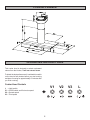
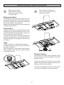
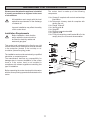
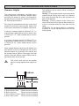
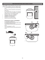
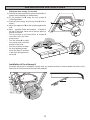
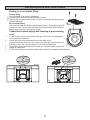
INSTRUCTION BOOKLET
COOKER HOOD
ZHC 95 ALU
IMPORTANT SAFETY INFORMATION
These warnings are provided in the interests of your safety. Ensure that you understand them all before
installing or using this appliance. Your safety is of paramount importance. If you are unsure about any of
the meanings of these warnings contact the Customer Care Department.
•
Installation
•
•
•
•
•
•
•
•
•
Any installation work must be undertaken by a
qualified electrician or competent person.
This hood must be installed in accordance with
the installation instructions and all
measurements adhered to.
If the cooker hood is installed for use above a
gas appliance then the provision for ventilation
must be in accordance with the Gas Safety
Code of Practice BS.6172, BS.5440 and
BS.6891 (natural gas) and BS.5482 (LP gas)
1994, the Gas Safety (Installation & Use)
Regulations, the Building Regulations issued by
the Dept. of the Environment, the Building
Standards (Scotland) (Consolidated)
Regulations issued by the Scottish
Development Department.
The fan motor of the cooker hood incorporates
a cut-out device, which will operate if the cooker
hood is installed below the minimum height
recommended in the Technical Information
section, or if the motor becomes overheated.
If the cut-out device is activated, switch off the
motor and allow the hood to cool. The cut-out
device will reset itself when the fan motor has
cooled.
It is dangerous to alter the specifications or
modify this product in any way.
When installed between adjoining wall cabinets,
the cabinets must not overhang the hob.
If the room where the hood is to be used
contains a fuel burning appliance such as a
central heating boiler then its flue must be of
the room sealed or balanced flue type.
If other types of flue or appliances are fitted
ensure that there is an adequate supply of air
to the room.
When the hood is used in conjunction with
appliances supplied with energy other than
electricity, the negative pressure in the room
must not exceed 0.04mbar to prevent fumes
being drawn back into the room by the hood.
•
The ducting system for this appliance must not
be connected to any existing ventilation system
which is being used for any other purpose.
Do not install above a cooker with a high level
grill.
Child Safety
•
The appliance is designed to be operated by
adults. Children should not be allowed to tamper
with the controls or play with the appliance.
During Use
•
•
•
•
This appliance is for domestic use only.
Never leave frying pans unattended during use
as over-heated fat and oil might catch fire.
Never do flambé cooking under this cooker
hood.
Do not leave naked flames under this hood.
Maintenance and Service
•
•
2
This appliance can be a fire hazard if the grease
and charcoal filters are not cleaned or replaced
as recommended.
Under no circumstances should you attempt to
repair the appliance yourself. Repairs carried
out by inexperienced persons may cause injury
or serious malfunctioning. Refer to your local
Zanussi Service Force Centre. Always insist on
genuine spare parts.
CONTENTS
For the Installer
For the User
Important Safety Information
Your Appliance
Operating Instructions
Maintenance and Cleaning
Something Not Working
Service and Spare Parts
Customer Care Department
Service Force Centres
Guarantee Conditions
2
4
4
5
6
6
6
7
9
Technical Information
Electrical Connections
Installing the Cooker Hood
3
10
10
11
YOUR APPLIANCE
OPERATING INSTRUCTIONS
This cooker hood is designed to extract unpleasant
odours from the kitchen, it will not extract steam.
To obtain the best performance it is advisable to switch
on the hood a few minutes before you start cooking
and leave it running for approximately 15 minutes after
you finish cooking.
Cooker Hood Controls
V1
L = Light switch
V1 = On/Off switch and first motor speed
V2 = Second speed
V3 = Third speed
4
V2
V3
L
MAINTENANCE AND CLEANING
Before carrying out any
maintenance or cleaning
isolate the cooker hood from
the mains supply.
The cooker hood must be kept
clean, a build up of grease or fat
can be a fire hazard.
Metal grease filters
It is necessary to wash these filters at least every two
months with warm water to which a little washing up
liquid has been added. Their compact size means that
they can be washed in the dishwasher.
Replace the metal grease filters by removing the filter
retaining clips (see below).
S36_29
Carbon filters
The carbon filters have to be replaced when they are
saturated, they cannot be cleaned and reused. They
should be replaced after approximately 4 months, or
sooner if the hood is used intensively.
To replace the carbon filters, remove the grease filters
and then the carbon filters push inwards on the two
retaining clips (G1) and disengage the security fixing
and remove.
Light
S36_30
The light consists of 2 x 20W halogen spotlights.
To replace the lights, remove the two screws that lock
the metal ring in place.
Take the spotlight out of the holder by pulling gently.
When replacing, ensure that the screws are firmly
inserted back in place.
G1
G1
External Cleaning
Any fat deposits should be removed regularly, at least
every two months. Avoid using abrasive or corrosive
cleaning products.
To clean the outside of the cooker hood, use a cloth
dipped in lukewarm water to which a small amount of
washing up liquid has been added.
S36_31
The inside of the appliance should be cleaned with a
soft cloth or brush dipped in warm soapy water.
5
SOMETHING NOT WORKING
If, having carried out these instructions carefully, your cooker hood fails to work properly please carry out the following
checks.
Symptom
Solution
The cooker hood will not start.
Check that the hood is connected to the
electricity supply.
Check that the fan speed control is on.
The cooker hood is not working effectively.
Is the fan speed high enough for the
task?
Is the grease filter clean?
Is the kitchen adequately vented to allow
the entry of fresh air.
If set up for re-circulation, check that the
charcoal filter is still effective.
If set up for extraction, check that the
ducting and outlets are not blocked.
The cooker hood has switched off during operation.
Has the safety cut-out tripped?
Turn off the hob and wait for the device
to reset.
If after all these checks, the problem persists, contact
your local Service Force Centre, quoting the model
number and serial number.
In-guarantee customers should ensure that the
above checks have been made as the engineer
will make a charge if the fault is not a mechanical
or electrical breakdown.
Please note that it will be necessary to provide proof
of purchase for any in-guarantee calls.
SERVICE AND SPARE PARTS
If you require an engineer or wish to purchase spare
parts contact your local Service Force Centre by
telephoning:
Customer Care Department
Zanussi
55-77 High Street
Slough
Berkshire
SL1 1DZ
08705 929929
Your telephone call will be routed to the Service Force
Centre covering your postcode area.
Telephone: 08705 727727 *
* calls to this number may be recorded for training
purposes.
For general assistance with your appliance or for
information on other Zanussi products please contact
our Customer Care Department by letter or telephone
at the address shown or visit our website at
www.zanussi.co.uk <http://www.zanussi.co.uk>.
6
7
8
GUARANTEE CONDITIONS
Standard Guarantee Conditions
We, Zanussi, undertake that if within 24 months of the date of the purchase this Zanussi built-in appliance or any
part thereof is proved to be defective by reason only of faulty workmanship or materials, the company will, at our
option, repair or replace the same FREE OF ANY CHARGE for labour, materials and carriage on condition that:
•
The appliance has been correctly installed and used only on the electrical supply stated on the rating plate.
•
The appliance has been used for normal domestic purposes only, and in accordance with the manufacturer’s
operating and maintenance instructions.
•
The appliance has not been serviced, maintained, repaired, taken apart or tampered with by any person not
authorised by us.
•
All service work under this guarantee must be undertaken by a Zanussi Service Force Centre.
•
Any appliances or defective parts replaced shall become the property of this company.
Home visits are made between 8.30am and 5.30pm Monday to Friday. Visits may be available outside these hours
in which case a premium will be charged.
EXCLUSIONS
This Guarantee does not cover:
•
Damage or calls resulting from transportation, improper use or neglect, the replacement of any light bulbs or
removable parts of glass or plastic.
•
Costs incurred for calls to put right appliances improperly installed or calls to appliances outside the United
Kingdom.
•
Appliances found to be in use within a commercial environment, plus those which are the subject of rental
agreements.
•
Products of Zanussi manufacture which were not marketed by Zanussi.
This guarantee is in addition to your statutory and legal rights.
ZANUSSI EUROPEAN GUARANTEE
If you move to another country within Europe then your guarantee moves with you to your new home subject to the
following qualifications:
•
The guarantee starts from the date you first purchased your product.
•
The guarantee is for the same period and to the same extent for labour and parts as exists in the new country
of use for this brand or range of products.
•
The product is installed and used in accordance with our instructions and is only used domestically, i.e. a
normal household.
•
The product is installed taking into account regulations in your new country.
Before you move please contact your nearest Customer Care centre, listed below, to give them details of your new
home. They will ensure that the local Service organisation is aware of your move and able to look after you and your
appliance.
France
Germany
Italy
Sweden
UK
Senlis
Nurnberg
Pordenone
Stockholm
Slough
+33 (0)3 44 62 29 99
+49 (0)911 323 2600
+39 (0)01678 47053
+46 (0)8 738 79 50
+44 (0)1753 219897
9
INSTALLATION INSTRUCTIONS
It is dangerous to alter the specifications or attempt to modify this product in any way.
Technical Information
DIMENSIONS
Height (CANOPY)
Height (CHIMNEY)
Width (CANOPY)
Width (CHIMNEY)
Depth
100 mm
450-850 mm
898 mm
200 - 270 mm
507 mm
Gross weight
Net weight
24,5 kg
20 kg
Ø120 mm
DUCTING OUTLET DIAMETER
ELECTRICAL SUPPLY:
POWER CONSUMPTION:
FAN MOTOR:
LAMP:
(2x40W halogen spotlights)
SUITABLE FOR
INSTALLATION ABOVE:
Electric Slot-In Cooker:
Gas Slot-In Cooker:
Electric Hob:
Gas Hob:
220-240V (50Hz)
180 W
140 W
40 W
13,5 KW
12,4 KW
7 KW
10 KW
NOTE: CE marking certifies that this appliance complies with the requirements laid
down in the EEC directive 89:336 (Electromagnetic Compatibility) and subsequent
modifications; EEC directive 73/23 (Low Voltage) and any subsequent modifications.
ELECTRICAL CONNECTION
This appliance must be earthed.
This appliance is fitted with a 3 core mains cable and
must be permanently connected to the electricity
supply via a double-pole switch having 3mm minimum
contact gap on each pole. A Switched Fuse
Connection Unit to BS1363 Part 4, fitted with a 3 Amp
fuse, is a recommendad mains supply connection
accessory to ensure compliance with the Safety
Requirements applicable to fixed wiring instructions.
Electrical Requirements
Any permanent electrical installation must comply with
the latest I.E.E. Regulations and local Electricity Board
Regulations. For your own safety this should be
undertaken by a qualified electrician e.g. your local
Electricity Board, or a contractor who is registered
with the National Inspection Council for Electrical
Installation Contracting (NICEIC).
This appliance conforms to BS 800: 1988 and
EEC Directive No. 78 308 regarding suppression of
radio and television interference.
Electrical Connection
Before connecting to the mains supply ensure that
the mains voltage corresponds to the voltage on the
rating plate inside the cooker hood.
10
INSTALLING THE COOKER HOOD
Please ensure that when the appliance is installed
it is easily accessible to an engineer in the event
of a breakdown.
The cooker hood is made up of the following
components:
1 No. Canopy C complete with controls and worktop
illumination.
1 No.Telescopic chimney stack A complete with
ducting fan unit.
1 No. Flange 120mm F
1 No. Venting grille G
1 No. Spigot R
1 No. Ducting conversion bend W
1 No. Support rod B
1 No. Fixing kit containing a wall bracket S to fix the
canopy hood, the cover and documentation.
All installation must comply with the local
authorities requirements for the discharge
of exhaust air.
Incorrect installation may affect the safety
of this cooker hood.
Installation Requirements
Before installation, check that the
wall to which the cooker hood is to
be fitted for electricity cables and
water and gas pipes.
S
This cooker hood is designed to be fixed to any rigid
vertical surface over a cooking area, and can be used
in the extraction (ducted to the outside) or recirculation (internal recycling) mode.
A
F
The installation work must be carried out by a qualified
electrician or competent person.
The manufacturer declines any responsibility for
damages due to incorrect installation of the cooker
hood or if the cooker hood is not installed in
compliance with relevant regulations controlling this
type of installation.
G
C
R
W
S36_01
Before unpacking the cooker hood position the carton
with the arrows pointing upwards as illustrated on the
carton.
B
11
INSTALLATION INSTRUCTIONS
This appliance can be used in either a ducting or
filtering mode.
Ducting – Cooking vapours and/or odours are passed
straight outside (ceiling and/or wall) via a disposal
duct, using the holes that are on the top and/or the
back of the appliance.
Filtering – Cooking vapours and/or odours are
removed from the air by 2 charcoal filters and the air
is then re-circulated around the room from the front
vents.
ATTENTION: For the filtering option it is absolutely
necessary to use the charcoal filters but not for the
ducting option.
Clearance Heights
The cooker hood is designed to be fitted over a
cooking appliance at the clearance heights stated,
providing the maximum output of the appliance
beneath does not exceed the maximums quoted in
the Technical Specifications.
If the output of the appliance below the cooker hood
exceeds the maximum outputs quoted, please refer
to the cooker manufacturer’s installation instructions.
A minimum clearance height of 650mm(25 1/2 ”) is
required when installed above a built-in electric hob,
or 700mm (27 1/2 ”) when installed above a built-in
gas hob.
A minimum clearance height of 685mm (27”) is
required when installed above a slot-in electric oven,
or 787mm (30 1/2 ”) when installed above a slot-in
gas oven.
When installed between adjoining wall cabinets, the
wall cabinets must not overhang the hob and the
distance between the underside of the cabinet and
the worktop must be 450mm. If the height of the wall
cabinet is less than 450mm a gap of 50mm must be
maintained either side of the hob.
This cooker hood must not be installed
above a cooking appliance with a high level
grill.
Hob
A: Built-in Electric Hob:
B: Built-in Gas hob:
C: Slot-in Electric Cooker:
D: Slot-in Gas Cooker:
650mm minimum clearance
700mm minimum clearance
685mm minimum clearance
787mm minimum clearance
12
INSTALLATION INSTRUCTIONS
S07_03
The versatility of the ducting fan unit on this hood
enables it to be installed in one of four different ways:
Air outlet directed upwards (re-circulation fitting
only).
Air outlet directed towards the wall (ducting
fitting only).
Air outlet directed to the right or left (ducting
fitting only).For correct installation of the hood,
please proceed in the following stages:
•
Selection of the type of installation
•
Installation of the hood canopy C
•
Installation of the chimney A
•
Ducting or re-circulation fitting
•
Electrical connection and testing
Selecting the type of installation
-
-
Air discharge towards the top
In this case the hood can be used in filter mode
Air discharge towards the wall
In this case the hood can only be used in suction
mode.
Side air discharge, Lh or Rh.
In this case the hood can only be used in suction
mode.
R
G
W
S07_30
-
13
R
W
INSTALLATION INSTRUCTIONS
Installation of the hood canopy C
Drilling the wall
a) Using the cardboard template provided, mark on the wall the centres of holes 1 for fixing of the hood canopy
C .The centre of hole 2 for fixing the chimney, (a) air outlet directed upwards or towards the wall, (b-c) air
outlet to the right or left hand side, must be marked at a distance X from the line between holes 1,obtained by
measuring the extension Z of the chimney required for installation, plus 18 mm X =Z +25-7.Using a Ø8 mm
drill bit, drill the points marked in this way.
5a
5b
5c
7
ø1
20
50
ø1
2
2
2
1
1
X
Z
105
105
1
1
1
39
25
1
ø8
S36_05
650
100 100
b) When installed with the air outlet directed towards the wall (a), it will be necessary to drill an air ducting
opening, measuring Ø120 mm, according to the diameter of the flange F provided.
Fitting the fixing elements
a) Insert the rawl plugs into holes 1 and 2 .
b) Fit the eye bolts O.
c) Fix the wall bracket S in hole 2 using the screw V (not supplied).
2
1
S
A08_07
A08_06
V
L=
44
mm
A
14
INSTALLATION INSTRUCTIONS
Fitting the hood canopy C to the wall
a) Remove the lower grill and the active charcoal filter if
present (see paragraph on maintenance).
b) Fit the support rod B using the two screws K
(3,5x9,5)provided.
c) Hook the hood canopy C to the eye bolts O fixed in
holes 1.
d) Adjust the support rod B so that it pushes against the
wall.
e) Adjusting position.There are two adjustable hooks at
the rear of the hood, which can be used to adjust its
position as follows:
- Turn the screws L until the position of screws N
coincides with the lower
access holes.
- Turn the screws N to adjust
the vertical and horizontal
O
position of the hood.
O
- Lock the screws L to fasten
the hood against the wall.
- Insert the plugs T provided
in the holes giving access to
screws N.
B
K
A08_08
S36_09
O
Installation of the chimney A
No matter which type of installation is being used, any wooden shelves in the area where the hood is to be
fitted must first be removed, drilled and later replaced.
N
L
S36_10
B
T
N L
A08_11
L
T
N
15
INSTALLATION INSTRUCTIONS
Drilling the shelves:
a) Using the cardboard template provided, and
taking hole “B ”as a point of reference, drill the
shelves along the central axis to allow the
passage of the chimney.
The chimney must be inserted into the shelves
before it is fixed to the hood canopy C.
b) When installing the re-circulation version with
the air outlet directed upwards, if the fan unit
is positioned below the line of shelves it will be
necessary to drill a suitable hole in the top shelf
only, to allow the air ducting pipe to pass
through.
Direction and position of the ducting fan
unit
a) The hood is normally supplied with the air outlet
directed towards the wall, if it is to be installed
with the air outlet directed to the right or left, it
will be necessary to change the direction of the
ducting fan unit, proceeding as follows:
- Unscrew the screws U;
- Turn the ducting fan unit 60 ° to the right or
left;
- Replace the screws U.
b) The ducting fan unit air outlets must be
arranged according to the type of installation
to be carried out.
· Air outlet directed upwards (re-circulation only)
- Remove the plastic plug from the upper part of
the venting grill and replace it on the rear part.
· Air outlet directed towards the wall.
- Remove the plastic frame from the air outlet.
S36_12
S36_13
U
S07_14
S07_22
U
A08_14
16
INSTALLATION INSTRUCTIONS
S07_16
- Remove the plug from the upper part of the ducting fan unit, as it is not
possible to insert the flange F with the plug in place.
- Fit the flange F Ø120 or 150 mm,replace the plug.
· Air outlet directed to the right or left hand side.
- Remove the four screws fastening the plastic frame, as shown in figure .
- Fit the ducting spigot R and replace the four screws removed as above.
Fixing the chimney
a) Loosen the screws M fixing the two parts of the chimney and pull the
inner section I almost all the way out. Remove the protective film P .
b) Rest the lower section of the chimney in its housing on the top of the hood
canopy. Lower the ducting fan unit until it reaches the wall bracket S and
fix it using the screw H provided.Fit the cover D
(provided) on the wall bracket S.
c) Fix the chimney to the hood canopy C using the
four screws provided.
d) Insert the transparent seal Q (provided),so as to
eliminate any play between the two parts of the
chimney . Lock the screws M.
e) Remove the support rod B .
R
S
H
S07_19
S
A08_21
I
D
P
M
A08_22
A08_20
E
E
E
Q
Q
E
A08_24
A08_23
17
INSTALLATION INSTRUCTIONS
Ducting or re-circulation fitting
Ducting fitting.
This is possible for all forms of installation:
a) Connect the air outlet to the external ducting system.
b) Remove the activated charcoal filter (if there is one)inside the hood canopy
(see Maintenance).
Re-circulation fitting
This is only possible with the air outlet directed upwards. Fit the venting grille G
onto the air outlet.The activated charcoal filter should be fitted inside the hood
canopy after connection to the power supply.
G
Connection to power supply and checking of good working
order
S07_23
1 - It is absolutely necessary to follow the warnings 3.2,3.3 and 3.4 of paragraph 3,
concerning safety measures.
2 - Loosen the two locking screws and remove the metal cover.
Connect the hood connection to the engine connection (a).Correctly place the
connectors under the cover and tighten the two locking screws (b).
3 - Once electrical connection has been carried out, check that lights, engine and
change of speed work.
4 - Fit the lower grill and the activated carbon filter (only for filter mode)(see Maintenance).
a
S36_26
b
18
S36_27
© Electrolux Household Appliances Limited 2001
4329478 03 - 010910