1
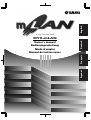
English
mLAN Interface Card
Français
Español
Owner’s manual
Bedienungsanleitung
Mode d’emploi
Manual de instrucciones
Deutsch
MY8-mLAN
MY8-(E).book Page 2 Thursday, October 11, 2001 10:05 AM
WARNING
Always follow the basic precautions listed
below to avoid the possibility of serious
injury or even death from electrical shock,
short-circuiting, damages, fire or other
hazards. These precautions include, but
are not limited to, the following:
• Do not attempt to disassemble or modify
the card. Do not apply excessive force to
card connectors or other card components. Mishandling of the card may lead to
shock, fire hazard, or equipment failure.
• Be sure to disconnect the power cable of
the main unit before installing this card (in
order to eliminate shock hazard).
CAUTION
Always follow the basic precautions listed
below to avoid the possibility of physical
injury to you or others, or damage to the
instrument or other property. These
precautions include, but are not limited
to, the following:
• The card is sensitive to static electricity.
Before handling the card, you should
briefly touch the metal casing of the main
unit with your bare hand to discharge any
static charge from your body. Failure to do
so may damage the card.
• Do not touch the metallic leads (pins) of the
circuit board when handling the card. The
pins are sharp and may cause hand cuts.
Yamaha cannot be held responsible for data loss or equipment damage caused by
inappropriate handling or use.
2
MY8-(E).book Page 3 Thursday, October 11, 2001 10:05 AM
Thank you for purchasing the Yamaha MY8-mLAN. The MY8-mLAN is an interface card that
provides mLAN interfacing. mLAN is a digital network designed for music and based on the IEEE
1394 high performance serial bus. mLAN makes it easy to construct sophisticated networks for
audio and MIDI signals that can be re-configured without changing the physical cabling (as was
necessary with previous systems).
The MY8-mLAN adds two mLAN connectors to the Yamaha AW4416 or AW2816 professional
audio workstations, or to the Yamaha 01V digital mixing console etc. (Consult your Yamaha
dealer for details of other applicable Yamaha equipment.)
English
Introduction
Package Contents
•
•
•
•
•
•
MY8-mLAN
mLAN Tools (CD-ROM)
IEEE 1394 cable (4.5 m)
Owner’s manual (this document)
mLAN guidebook
mLAN Tools installation guide
About the included CD-ROM
The included CD-ROM contains software that is useful when used in conjunction with the
MY8-mLAN. This software includes “mLAN Patchbay” which lets you make settings on
your computer to specify the routing of audio/MIDI signals between mLAN devices connected to the MY8-mLAN. For details refer to the separate “mLAN Tools Installation
Guide.”
Yamaha cannot be held responsible for damage caused by improper use or
modifications to the instrument, or data that is lost or destroyed.
The illustrations shown in this Owner’s Manual are for instructional purposes only, and may
appear somewhat different from those on your device.
The company names and product names in this Owner’s Manual are the trademarks or registered
trademarks of their respective companies.
3
MY8-(E).book Page 4 Thursday, October 11, 2001 10:05 AM
Table of Contents
Introduction ................................................................................... 3
English
Package Contents........................................................................... 3
How to install the MY8-mLAN ....................................................... 5
Names and Functions..................................................................... 6
DIP switch (SW1) settings.............................................................. 7
Connections.................................................................................. 10
About mLAN connections ............................................................ 11
Internal Configuration of the MY8-mLAN................................... 12
LED Messages ............................................................................... 13
Specifications................................................................................ 14
4
MY8-(E).book Page 5 Thursday, October 11, 2001 10:05 AM
How to install the MY8-mLAN
1. Set the MY8-mLAN’s DIP switch (SW1) according to your application. For details refer to page
NOTE
It is not possible to change the setting of the DIP switch (SW1) after the MY8-mLAN is
installed. You must set the DIP switch before installation. If you want to change the settings,
you must turn off the host device, remove the MY8-mLAN, and then change the settings.
2. Install the MY8-mLAN into your device. For details refer to the operation manual for your
English
7.
device.
WARNING
You must turn off the power of your device before you begin installing the MY8-mLAN.
3. Connect the device into which the MY8-mLAN was installed to your other mLAN (IEEE 1394)
devices or IEEE 1394-compatible computer. For details refer to page 10.
4. Make mLAN connection settings. For details refer to page 12.
MY8-mLAN Installation Precautions
• Before beginning installation, switch off the power to the main unit and any connected peripherals, and unplug them from the power outlet. Then remove all cables connecting the main
unit to other devices. (Leaving the power cord connected while working can result in electric
shock. Leaving other cables connected can interfere with the installation procedure.)
• It is recommended that you wear gloves to protect your hands from sharp or pointed projections on the equipment.
• Board components may be damaged by electrostatic discharge. Be sure to drain any electrostatic charge from body and clothes before starting work. Keep hands clear of board components, board circuitry, and metallic leads while carrying out the installation.
• Handle the plug-in boards with care. Dropping or subjecting the card to any kind of shock may
cause damage or result in a malfunction.
• Do not touch the exposed metal parts in the circuit board. Touching these parts may result in a
faulty contact.
• Take care to avoid dropping screws into the main unit. If a screw does fall in, be sure to remove
it before you reassemble and power up the unit. Starting the unit with a loose screw inside may
lead to improper operation or to equipment failure. (If you are unable to retrieve a dropped
screw, consult your Yamaha dealer for advice.)
5
MY8-(E).book Page 6 Thursday, October 11, 2001 10:05 AM
Names and Functions
English
1
2
3
A mLAN (IEEE1394) jacks
These jacks are used to connect mLAN devices or IEEE1394-compatible devices via IEEE1394 standard (6-pin) cables. Each jack has an LED in the upper left corner to indicate the following statuses.
green : The MY8-mLAN or connected device is a “leaf” node.
off
: Not connected.
red
: When there is a possibility that the sound will be interrupted.
NOTE
If you disconnect the cable from the jack or turn off the power of the device when the LED is lit
red, the sound on the bus (system) will be momentarily interrupted.
B RT/ERR LED
This LED indicates the following statuses.
green : The MY8-mLAN is a “root” node.
orange : An IEEE 1394 bus-related error has occurred.
red
: Another type of error has occurred.
off
: Normal operating condition other than the above.
NOTE
Refer to “LED Messages” on page 13 for information on the error indication.
C ACTIVE LED
This LED indicates the following statuses.
blue
: The relay function between mLAN (IEEE 1394) jacks is active.
off
: The relay function between mLAN (IEEE 1394) jacks is inactive.
NOTE
6
Since the MY8-mLAN will stop functioning as a bus relay when the power of the main unit is
turned off, this LED will also correspond to the power on (lit blue) or off (dark) status.
MY8-(E).book Page 7 Thursday, October 11, 2001 10:05 AM
DIP switch (SW1) settings
English
The MY8-mLAN has a switch that specifies whether audio input/output and MIDI input/output via
mLAN will be enabled.
In this switch, moving the white slider toward the number will turn the setting “OFF,” and moving
it toward the side marked ON will turn the setting “ON.” The following settings are assigned to
each number 1–8.
Audio OUTPUT-Plug 1-8 (ON enables, OFF disables)
This specifies whether the audio output plugs will be enabled or disabled.
If this is ON, the eight audio output plugs will be enabled.
If this is OFF, the audio output plugs will be disabled.
Audio INPUT-Plug 1-8 (ON enables, OFF disables)
This specifies whether the audio input plugs will be enabled or disabled.
If this is ON, the eight audio input plugs will be enabled.
If this is OFF, the audio input plugs will be disabled.
MIDI INPUT-Plug, OUTPUT-Plug (ON enables, OFF disables)
This specifies whether the MIDI input/output plugs will be enabled or disabled.
If this is ON, one MIDI output plug and one MIDI input plug will be enabled.
If this is OFF, the MIDI plugs will be disabled.
–
MY8-mLAN number
This specifies the number of the module name.
When you are using multiple MY8-mLAN units together, use these ON/OFF switches to specify a number that will distinguish each unit from the others. This will be reflected in the module name (e.g., “MYmLAN31”) used when you make mLAN connection settings. When you
are using multiple MY8-mLAN units, there will be no problems with operation even if each
unit is set to the same number. However if you assign a different number to each unit, you will
be able to distinguish between units by the different module name that is displayed for each
unit when controlling them from software such as “mLAN Patchbay.”
NOTE
For details about mLAN connections/plugs, see page 11.
7
English
MY8-(E).book Page 8 Thursday, October 11, 2001 10:05 AM
Number
Module name displayed for
connection setting
OFF
OFF
OFF
OFF
OFF
—
Do not use this setting
ON
OFF
OFF
OFF
OFF
1
MYmLAN01(factory setting)
OFF
ON
OFF
OFF
OFF
2
MYmLAN02
ON
ON
OFF
OFF
OFF
3
MYmLAN03
OFF
OFF
ON
OFF
OFF
4
MYmLAN04
ON
OFF
ON
OFF
OFF
5
MYmLAN05
OFF
ON
ON
OFF
OFF
6
MYmLAN06
ON
ON
ON
OFF
OFF
7
MYmLAN07
OFF
OFF
OFF
ON
OFF
8
MYmLAN08
ON
OFF
OFF
ON
OFF
9
MYmLAN09
OFF
ON
OFF
ON
OFF
10
MYmLAN10
ON
ON
OFF
ON
OFF
11
MYmLAN11
OFF
OFF
ON
ON
OFF
12
MYmLAN12
ON
OFF
ON
ON
OFF
13
MYmLAN13
OFF
ON
ON
ON
OFF
14
MYmLAN14
ON
ON
ON
ON
OFF
15
MYmLAN15
OFF
OFF
OFF
OFF
ON
16
MYmLAN16
ON
17
|
29
MYmLAN17
|
MYmLAN29
Same as numbers 1–13
OFF
ON
ON
ON
ON
30
MYmLAN30
ON
ON
ON
ON
ON
31
MYmLAN31
By setting these settings appropriately for the device in which the MY8-mLAN is installed, you can
construct an uncluttered and stable system.
For example on a device such as the Yamaha DA-824 (D/A converter) which provides only the
audio INPUT-Plugs described in , enabling the audio OUTPUT-Plugs described in will cause an
invalid plug to be displayed when you make mLAN connection settings, even though audio is not
actually being output to the mLAN bus. On systems that have plug information for numerous
devices, this will complicate the situation.
8
MY8-(E).book Page 9 Thursday, October 11, 2001 10:05 AM
DIP switch settings for typical applications
This device performs A/D conversion of analog audio input, and sends it to other devices on
the mLAN bus. Thus for the MY8-mLAN installed in this device, only the audio output plugs
are valid, and the audio input plugs and MIDI input/output plugs are invalid.
Set the DIP switches as follows.
1-ON, 2-OFF, 3-OFF,
4–8 may be set as desired. (However, be sure not to turn all of them OFF.)
■ When the MY8-mLAN is installed in the Yamaha DA824
English
■ When the MY8-mLAN is installed in the Yamaha AD824
This device performs D/A conversion of digital audio from another device on the mLAN bus,
and outputs it as analog audio. Thus for the MY8-mLAN installed in this device, only the audio
input plugs are valid, and the audio output plugs and MIDI input/output plugs are invalid.
Set the DIP switches as follows.
1-OFF, 2-ON, 3-OFF,
4–8 may be set as desired. (However, be sure not to turn all of them OFF.)
■ Yamaha AW4416 earlier than version 2.0 (not including 2.0)
This version does not support the MY8-mLAN. Please upgrade to version 2.0 or later.
■ When the MY8-mLAN is installed in the Yamaha AW4416 version 2.0 or later
• When installed in slot 1
Slot 1 transmits/receives audio data to/from other devices on the mLAN bus. It does not transmit or receive MIDI data. Thus for the MY-mLAN installed in slot 1, the audio output plugs and
audio input plugs are valid, and the MIDI plugs are invalid.
Set the DIP switches as follows.
1-ON, 2-ON, 3-OFF,
4–8 may be set as desired. (However, be sure not to turn all of them OFF.)
• When installed in slot 2
Slot 2 transmits/receives audio and MIDI data to/from other devices on the mLAN bus. Thus
for the MY8-mLAN installed in slot 2, the audio output and input plugs as well as the MIDI
input/output plugs are valid.
Set the DIP switches as follows.
1-ON, 2-ON, 3-ON,
4–8 may be set as desired. (However, be sure not to turn all of them OFF.)
■ When the MY8-mLAN is installed in the Yamaha AW2816 earlier than version 1.1
(not including 1.1)
This version does not support the MY8-mLAN. Please upgrade to version 1.1 or later.
■ When the MY8-mLAN is installed in the Yamaha AW2816 version 1.1 or later
This device transmits/receives audio and MIDI data to/from other devices on the mLAN bus.
Thus for the MY8-mLAN installed in this device, the audio output and input plugs as well as
the MIDI input/output plugs are valid.
Set the DIP switches as follows.
1-ON, 2-ON, 3-ON,
4–8 may be set as desired. (However, be sure not to turn all of them OFF.)
9
MY8-(E).book Page 10 Thursday, October 11, 2001 10:05 AM
Connections
Here’s how to make connections from the MY8-mLAN to other mLAN devices or to your computer.
English
Connecting an mLAN (IEEE1394) device
Use an IEEE 1394 standard cable (6 pin) to connect the mLAN (IEEE 1394) jack of the MY8-mLAN
to the mLAN (IEEE 1394) connector of the other mLAN (IEEE 1394) device. When doing so, it is
not necessary to turn off the power of the mLAN (IEEE 1394) device or the host device in which
the MY8-mLAN is installed.
mLAN (IEEE1394) device
MY8-mLAN
IEEE1394
standard cable
IEEE1394 standard cable
Macintosh computer
that supports FireWire
CAUTION
Do not insert or remove the MY8-mLAN while the power of the host device is turned on.
10
MY8-(E).book Page 11 Thursday, October 11, 2001 10:05 AM
About mLAN connections
• Use the “mLAN Patchbay” application program to make settings from a Macintosh computer
that is equipped with a FireWire port.
• Use the “mLAN Patchbay” application program to make settings from a Windows computer
that is equipped with a COM port or other serial port. (However, you will need another mLAN
device that has a serial port.)
• Make settings from an mLAN-compatible device (such as the mLAN8P or a synthesizer in which
the mLAN option is installed).
English
If you want to use an IEEE 1394 cable to connect mLAN-compatible devices via their IEEE 1394
(FireWire) connectors and exchange audio or MIDI signals, you must make connection settings.
There are three ways to make connection settings.
The type of system in which the MY8-mLAN is being used will determine which of the above
three methods you use to make settings.
For each MY8-mLAN unit, eight channels of audio and one set of MIDI signals can be input and
output. When making mLAN connection settings, these audio and MIDI inputs and outputs are
handled as “plugs” — virtual connectors with a name assigned to each.
Each audio or MIDI output from the MY8-mLAN to another mLAN device is called an “OUTPUTPlug,” and each audio or MIDI input received by the MY8-mLAN from another mLAN device is
called an “INPUT-Plug.” Connections are made by connecting these plugs.
NOTE
For more information about mLAN connections/plugs, refer to the mLAN Guide Book.
11
MY8-(E).book Page 12 Thursday, October 11, 2001 10:05 AM
Internal Configuration of the
MY8-mLAN
English
The signal flow within the MY8-mLAN is shown by the following diagram.
mLAN device
mLAN jacks1, 2
mLAN
MIDI IN
mLAN
MIDI OUT
mLAN MIDI/
MIDI
conversion
MIDI/
mLAN MIDI
conversion
mLAN audio input
mLAN audio output
mLAN audio/Audio direct conversion
Audio/mLAN audio direct conversion
MY8-mLAN
OPTION I/O slot
AW4426, 01V, etc.
mLAN signals
non-mLAN signals
12
mLAN cables
MY8-(E).book Page 13 Thursday, October 11, 2001 10:05 AM
LED Messages
LED messages
mLAN1, 2
Indicates the status of the mLAN (IEEE
1394) jack.
RT/ERR
Indicates “root” node and error.
ACTIVE
Indicates the status of the relay function
between mLAN (IEEE 1394) jacks.
Status
Red ..... Disconnecting the connection will
interrupt the sound on the bus
(system).
Green... The connection is a “leaf” node.
Red/Orange ... An error has occurred.
Green ... The MY8-mLAN is a “root”
English
Function
node.
Blue ... The relay function is enabled.
Error messages
mLAN*
2
1
red
orange
orange The power to the bus is insufficient.
green
red
red
Cause
The topology of the connected devices
creates a loop.
Cycle Start Packet is not transmitted to
orange the bus. (Audio/MIDI data cannot be
transmitted.)
A malfunctioning device exists on the
red
orange
bus.
green orange The number of hops exceeds 16.
red
red
RT
red
red
red
MIDI IN transfer rate is not correct.
Data transmission exceeds the MIDI
transfer rate.
The sound is interrupted for some reason, or the devices are not syncing.
Action
Check to see if any part of the connection
creates a loop.
Remove the malfunctioning device.
Remove the malfunctioning device.
Check the number of hops.
Add a power provider to the bus, or
remove a power consumer from the
bus.
Check the MIDI transfer rate setting.
Check to see if the transmitting device
is operating properly.
Check the word clock setting.
* If the RT/ERR LED is lit green or is dark, these LEDs indicate the status of the mLAN (IEEE 1394) jacks.
13
MY8-(E).book Page 14 Thursday, October 11, 2001 10:05 AM
English
Specifications
mLAN
IEEE1394 High Performance Serial Bus
Data Rate S200, Isochronous Resource Manager capable, Bus Manager capable,
Connection Manager
Conforms to IEC61883-6 Audio and Music Protocol
Digital Audio 8in/8out, MIDI 1in/1out
Sampling rate
44.1 kHz, 48 kHz
Jacks
Front: mLAN IEEE1394 (1/2), Rear: OPTION I/O slot connector
Display
mLAN 1/2 LED, ACTIVE LED, RT (Root)/ERR (Error) LED
Power consumption
2.2 W (440 mA/+5 V)
Specifications and descriptions in this owner’s manual are for information purposes only. Yamaha Corp. reserves the right
to change or modify products or specifications at any time without prior notice.Since specifications, equipment or options
may not be the same in every locale, please check with your Yamaha dealer.
14
MY8-(E).book Page 15 Thursday, October 11, 2001 10:05 AM
English
MEMO
15
MY8-(E).book Page 16 Thursday, October 11, 2001 10:05 AM
English
MEMO
16
MY8-Hyo4.fm Page 13 Thursday, September 20, 2001 9:26 AM
YAMAHA CORPORATION
This document is printed on recycled chlorine free (ECF) paper with soy ink.
Auf Recycling-Umweltpapier gedruckt.
Ce document a été imprimé sur du papier recyclé non blanchi au chlore.
Este documento se ha impreso reciclado en papel sin cloro alguno.
Pro Audio & Digital Musical Instrument Division
P.O. Box 3, Hamamatsu, 430-8651, Japan
© 2001 Yamaha Corporation
V000000 010APAP2.2-02A0 Printed in Japan