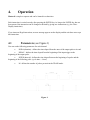
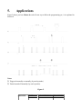
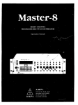
1
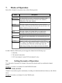
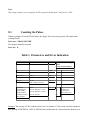
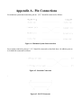
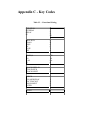
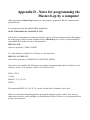
Master-8 Instruction Manual
Thank you for buying Master-8.
Master-8 is an 8-channel pulse generator, based on advanced microprocessor technology.
Master-8, the flexible pulse generator, has many useful features. You will find that Master-8 is user
friendly and the programming simple and easy to learn. Master-8 is an attractive unit and you will
enjoy using its eight paradigms.
Please read this manual carefully and become familiar with all the possible options and operating
modes
Table of Contents
1. Introduction
1.1 General
2. Front and Rear Panel Description
2.1 Front Panel
2.2 Rear Panel
3. Theory of Operation
4. Operation
4.1 Parameters
5. Applications
6. Programming Master-8
7. Modes of Operation
7.1 Setting the modes of Operation
8. Setting Parameters
8.1 Using the ‘’ and ‘↓’ Keys
8.2 Setting the ‘M’ Parameter
8.3 Counting the Pulses
9. Triggering
9.1 Manual Triggering
9.2 Setting the internal connections:
9.3 External Inputs
10. Eight Stored Paradigms
10.1 Transferring to another Paradigm
10.2 Copying Paradigms
11. Clearing the Memory
12. Verification Checks
13. Clock Options
13.1 Clock
13.2 Stop-Watch
13.3 Timer
14. Master-8-cp
14.1 Programming by a computer
14.2 Communication
14.3 Communication between Master-8-cp and a terminal
Appendix A - Pin Connections
Appendix B - Setting the baud-rate and character format
Appendix C - Key Codes
Appendix D - Notes for programming the Master-8-cp by a computer
1.
Introduction
Master-8 is an 8-channel stimulator/pulse generator which enables you to switch your set-up between
completely different experiments (paradigms). Master-8 stores eight user’s preprogrammed paradigms.
Each paradigm can use all eight channels.
Using Master-8, switching between two different protocols is easily accomplished. Set-up can be
switched to the selected setting by using a single command. This option is very useful in the following
cases:
a. where the current protocol requires modification during the course of the experiment.
b. where several users with identical set-ups require retrieval of their specific settings from the
Master-8 memory.
1.1
General
A lithium battery with a guaranteed life of 7 years ensures that all parameters of the 8 paradigms are
stored in the memory even after the power is switched off, unless the parameters are changed.
Therefore, there is no need to reinsert the parameters when switching on the system.
2.
2.1
Front and Rear Panel Description
Front Panel
The Front Panel contains four main sections:
−
−
−
−
Power Switch and Power On Indicator
Front Panel keys
Input Section
Output Section
One. Power Switch and Power On Indicator:
The power switch and the power ON indicator are located on the lower left side of the front panel.
Two. Front Panel Keys
The front panel keys are color-coded and comprise 5 groups as follows:
1. Digits: 0 to 9.
2. Operation mode keys: FREE (Free Run), TRAIN, TRIG, DC, GATE, OFF.
3. Parameter keys: DURA (Duration), DELAY, INTER (Interval Time), M (No. of pulses
per train), ‘’, ‘↓’.
4. Clock keys: CLOCK-DISPLAY, STOP WATCH, CLOCK-RESET, TIMER.
5. Command keys: CLEAR-DISPLAY, CONNECT/DISCONNECT, CHECK, ENTER,
RESET.
Note:
Some of the keys perform a dual function
The key code is painted on the key. For example, the code of FREE is FR. Pressing a
key will result in a response on the display screen.
Three. External Input Section
You will find the external input section is located on the right hand side of the key section. This section
is divided into two, parts - EXT1 for channel 1 and EXT2 for channel 2. Each has a BNC socket and an
ON/OFF switch for enabling or disabling the input.
Four. Output Section
On the panel from the top down are: the channel number, a LED indicating that the channel is active, a
switch for selecting the polarity of the output pulses, a knob for adjusting the output amplitude, and a
BNC socket for connecting the output to external devices.
Outputs ‘2+3’, ‘4+5’ and ‘6+7+8’ are the summations of outputs ‘2+3’, ‘4+5’ and ‘6+7+8’
respectively. You can use these sockets for multi-level pulses (e.g. +/- pulses). The two switches add
the summations ‘2+3’ and /or ‘6+7+8’ to the ‘4+5’ output, resulting in the ‘4+5’ output delivering up to
7 pulse levels +GND.
2.2
Rear Panel
The rear panel contains the following components:
a. A switch to connect or disconnect the ground to/from the chassis.
reduce the noise level of the system.
You can also use this switch to
b. An RS-232 interface to communicate with a computer (for the Master-8-cp and Master-8-VP
models).
3.
Theory of Operation
Each channel operates independently in one of the following modes:
•
FREE-RUN - the channel delivers pulses continuously
•
TRIGGER - following a trigger, the channel delivers a single pulse
•
TRAIN - following a trigger, the channel delivers a train of pulses
•
DC - the channel is time independent, it can be turned on and off manually
•
GATE (channels 1 and 2 only) - the channel delivers pulses continuously while it is
externally gated
You can connect the channels internally to each other, therefore there is no need to connect wires
between the channels.
The Master-8-cp model can be programmed by a computer via a standard RS-232 interface. The
communication is bi-directional.
Channels 1 and 2 can receive external triggers. This enables synchronizing channels with external
devices.
Master-8 features a clock which measures the time that has elapsed after pressing the CLOCK
-RESET key (e.g. the experiment time). It also features a timer which can change the mode of a
channel at a certain hour (i.e. turn the channel on or off).
You can adjust the amplitude of the output pulses from -10V to +10V, with a maximum current of
20mA.
4.
Operation
Master-8 is simple to operate and can be learned in a short time.
Each instruction is carried out only after pressing the ENTER key. As long as the ENTER key has not
been pressed, the instruction can be changed or deleted by giving new instructions (e.g. the ClearDisplay instruction).
If you insert an illegal instruction, an error message appears on the display and the unit does not accept
this instruction.
4.1
Parameters (see Figure 1)
You can set the following parameters for each channel:
•
DURA (duration) - defines the time elapsed from the onset of the output pulse to its end.
•
DELAY - defines the time elapsed from the beginning of the input trigger to the
beginning of the output pulse.
•
INTER (interval) - defines the time elapsed between the beginning of a pulse and the
beginning of the following pulse. (cycle time = 1/rate).
•
M - defines the number of pulses per train in the TRAIN mode.
Figure 1.
5.
Applications
Figure 2 shows you how Master-8 works. Do not try to follow the programming yet, it is explained in
Section 6.
Notes:
➀ Triggered externally or manually (by one keystroke)
➁ Turned on and off manually (by one keystroke).
Figure 2.
CHANNEL
MODE
PARAMETERS IN TRIGGERED
USE
BY
#3
FREE-RUN
duration. Interval
none
#2
TRIG
duration, delay
#3
#4
TRAIN
duration, interval, M #2 & #3
#5
DC
none
none
A special feature of Master-8 is the 3 multilevel outputs which you can use for multilevel pulses (e.g.
+/- pulses). These OUTPUTS are ‘2+3’, ‘4+5’ and ‘6+7+8’ respectively.
Close to the ‘4+5’ output there are two switches. You can use these switches to add the summations
‘2+3’ and/or ‘6+7+8’ to the ‘4+5’ output, thus the ‘4+5’ output can deliver up to 7 level pulses + GND.
Examples of outputs that you can obtain through the ‘4+5’ output are shown in Figure 3.
Figure 3.
6.
Programming Master-8
This section demonstrates how to program the Master-8. Please follow the instructions and notice how
simple and straightforward they are.
Notes:
1. Each instruction is followed by a reference enabling you to find more details on a similar
instruction.
2. Before continuing, make sure that you are familiar with the location of different keys (see item 2.1).
Before you begin to program, the entire Master-8 memory must cleared.
Press keys: ‘OFF, ALL, ALL, ALL, ENTER’ (see Section 11)
This instruction clears all paradigms of Master-8. Now you are ready to program it.
1. Set channel #1 to the FREE-RUN mode.
.
Press keys: ‘FREE, 1, ENTER’ (see Section 7).
Channel #1 now delivers pulses continuously. Since you have not yet set the time parameters, the
channel is running with its default times: 0.1 sec duration and 0.2 sec interval (from the beginning of a
pulse to the beginning of the next one).
2. Set the duration time of channel #1 to 9.5 msec.
The format of 9.5 msec. will be 9.5 x 10⁻³ sec. (or several other formats, see Section 8).
Press keys: ‘9.5, ENTER,3,ENTER’.
(‘3’ for msec. For seconds use ‘0’, for µsec use ‘6’). The duration of channel #1 is now exactly 9.5
msec. (Please check with an oscilloscope).
Set the interval time of channel #1 to 2 sec.
Press keys: ‘INTERVAL,1,2,ENTER,0,ENTER’.
(The ‘0’ indicates that you are counting in seconds.) Now channel #1 is running in the FREE-RUN
mode. Its duration time is 9.5 msec. and its interval is 2 sec.
3. Set channel #2 to the trigger mode.
Press keys: ‘TRIG, 2, ENTER’ (see Section 7)
Nothing happens, this is because Channel #2 is now in the TRIGGER mode, but is waiting to
accept a trigger. You can trigger it in 3 ways:
a) MANUAL TRIGGERING Press key: ‘2’.
(‘2’ is the channel number.) Note that each press on ‘2’ delivers the triggered pulse. Press ‘2’ several
times.
b) EXTERNAL TRIGGERING Whenever there is an input pulse in the ‘EXT 2’ input it triggers channel #2 (see Section 9).
c) INTERNAL TRIGGERING You can internally connect each channel to any number of the other channels (see Section 9).
4. Connect channel #1 internally to channel #2 Press keys: ‘CONNECT,1,2,ENTER’ to connected. (see
Section 9).
Each output of channel #1 triggers channel #2.
Notes:
One.You don’t have to worry about the amplitude or polarity of the trigger source.
Two.The instruction itself is very straightforward (i.e. similar to the way you would say it: “CONNECT from #1 to #2, ENTER”).
Three.You can add manual pulses by pressing ‘2’.
5. Set the duration of channel #2 to be 15 msec. Press key: DURA,2,15,ENTER,3,ENTER’ (see Section 8)
6. Set the delay of channel #2 to be 100 msec. Press keys: DELAY,2,100,ENTER,3,ENTER’ (Please check the new delay).
7. Set channel #3 to the train mode.
Press keys: ‘TRAIN,3,ENTER’.
Channel #3 is now in the TRAIN mode and is waiting for a trigger.
8. Trigger it manually by pressing key ‘3’ (see Section 9)
You then obtain the train of pulses.
9. PULSES PER TRAIN
Set the number of pulses per train of channel #3 to be ‘5’.
Press keys : ‘M,3,5,ENTER,0,ENTER’ (see Section 8).
Trigger Channel #3 manually again by pressing ‘3’.
10. Connect channel #1 to trigger #3.
Press keys: CONNECT,1,3,ENTER (see Section 9).
Channel #1 will now trigger both channels #2 & #3.
Note:
The ‘→’ sign on the panel above the ‘1.4’ digits. This arrow indicates the direction of the connection.
To demonstrate Master-8’s most powerful feature
Assume that you programmed all the 8 channels to run in a specific pattern (your present experiment)
and now you want to switch to a new pattern (PARADIGM) that also uses all the 8 channels. With
Master-8 you can do this very easily. But first you have to program the other paradigms.
11. Press key: ‘ALL’
The name of the present paradigm (‘1’) is displayed.
In order to switch to paradigm #5,
Press keys: ‘5,ENTER’ (see Section 10).
Note:
Since this is a new paradigm all the channels are off, all the internal connections are
disconnected and all the time parameters have their default values.
12. Set all the 8 channels to the FREE-RUN mode
Press keys: ‘FREE,1,ENTER’, ‘FREE,2,ENTER’. Etc.
Each of the 8 channels now runs continuously at its own rate, independently of the other channels.
13. Now you can switch back to the previous paradigm by recalling it.
Press keys: ‘ALL,1,ENTER’ and you obtain the previous paradigm.
Press keys: ‘ALL,5,ENTER’ and you obtain the other one. All the channels are now working in
synchronization since you started them together.
14. Turn the power off.
Notes:
a. Master-8 stores all the 8 paradigms even when the power is turned off.
b. There is a lithium battery for memory retention. (This battery need only be replaced
after 7 years).
15. Switch the power on. Master-8 immediately continues working in the last paradigm, exactly as
before you switched the power off.
16. Switch to paradigm #1.
Press keys: ‘ALL,1,ENTER’.
Note: this paradigm is also stored in the memory after switching the power off.
17. Before continuing, clear all the Master-8 memory Press keys: ‘OFF,ALL,ALL,ALL,ENTER’. (see Section 10).
Dear User,
The last section was a brief demonstration of how to use Master-8.
Now you have a rough idea of how Master-8 works. However, here are many instructions that you are
not yet familiar with e.g. DC, GATE, CHECK, TIMER. Even the features that are demonstrated above
are only partially demonstrated.
Please read the rest of this manual carefully so that you will not miss any important feature. Sections 7
to 13 deal with the operation of Master-8. Section 14 and Appendices A,B,C and D are about the
communication of Master-8-cp with a computer.
7.
Modes of Operation
Each of the 8 channels can operate in one of the following modes:
Mode
Description
FREE RUN
The channel delivers pulses continuously according to the
programmed duration and interval times. The channel is
independent of the other channels.
TRAIN
Following a trigger, the channel delivers a train of pulses
according to the programmed duration and interval times. The
number of pulses per train is set by ‘M’.
TRIG
Following a trigger, the channel delivers a single pulse
according to the programmed delay and duration times.
DC
The channel is time independent, you can manually turn it on
and off.
GATED
Channels 1 and 2 can be externally gated via the EXT1 or
EXT2 inputs. The channel delivers pulses continuously while
it is externally gated. When the external input stops, the
channel stops working. A new input reactivates the channel.
In either TRAIN or TRIG mode you can trigger the channel in the following ways:
1. Manually
2. The internal connections
3. EXT1 (for channel 1 only) EXT2 (for channel 2 only)
7.1
Setting the modes of Operation
To set the mode of operation of a channel, first press the selected mode key and then the channel
number.
Example 1: In order to set channel #2 to the FREE-RUN mode Press keys: ‘FREE,2,ENTER’.
Channel #2 now delivers pulses continuously according to its duration and interval times (or the default
times).
Example 2: In order to set channel #3 to the TRAIN mode -
Press keys: ‘TRAIN,3,ENTER’.
Channel #3 is now in the TRAIN mode. You can trigger it in several ways. Trigger it now manually by
pressing ‘3’ (channel number)
Example 3: To set channel #5 in the DC mode Press: ‘DC 5 ENTER’
Channel #5 is now in the DC mode, it is time independent and delivers a continuous pulse. You can
manually stop and start the pulse by pressing ‘5’ (channel number)
Example 4: To turn off all the channels Press keys: ‘OFF,ALL,ENTER’.
8.
Setting Parameters
To set the time parameters (DURA, DELAY or INTER), first press the selected parameter key and then
the desired time.
Example: To set the duration of channel 6 to be 52 msec (52 x 10-3 sec, the time is given in seconds).
Press keys: ‘DURA,6’
(the previous duration is displayed. If the duration time has never been set, the sign ‘FFFF FF’ is
displayed).
Press keys: ’52,ENTER,3,ENTER’. (‘3’ for msec)
For your convenience it is recommended to use only exponents of 6 (µsec), 3 (msec) or 0 (sec).
- e.g. 52 msec can be inserted also as 0.052 x 100 sec, or 5.2 x 10⁻²sec, or 5200 x 10-5 sec etc.
Note:
The new parameter becomes operative, the instant you press the last ENTER.
8.1
Using the ‘’ and ‘↓’ Keys
You can increase or decrease each time parameter using the ‘’ and ‘↓’ keys.
Example:
Press keys: ‘DURA,6’.
By holding down the ‘’and ‘↓’ keys, you will change the duration of
channel 6.
Note: the change takes place only when releasing the key.
Press key: ‘CLEAR DISPLAY’ in order to clear the display.
8.2
Setting the ‘M’ Parameter
Example: To set M=80 pulses per train for channel 8 Press keys: M,8. The previous M8 is displayed.
Press keys:’80,ENTER,0,ENTER.
Note:
Only integer numbers are accepted for M. The exponent should equal 1 only for M > 9999.
8.3
Counting the Pulses
Whenever channel 8 is in the TRAIN mode, the display shows how many pulses still remain in the
existing TRAIN.
Press keys: ‘TRAIN,8,ENTER’.
Now trigger channel 8 manually
Press key: ‘8’.
Table 1. Parameters and Error Indication
Parameter
Min
Max
Error indication for illegal
values.
(x is the channel number)
M
1
59,900
Mx
Err
DURATION
40µsec
3999 sec
Dx
Err
DELAY
100µsec
Delay> Duration/10,000
3999 sec
Lx
Lx
Err
Err
INTERVAL
a)Normal usage:
b)Train Mode:
c)If the channel
internally activates
other channels:
60µsec
Interval> Duration + 9µsec
Interval> Duration + 59µsec
3999 sec
Ix
Rx
Tx
Err
Err (Rate err)
Err (Train err)
Err (Connect err)
Interval >500µsec
Cx
Example: The message ‘R7 Err’ indicates ‘Rate error’ on channel #7. The reason is that the channel is
now running in FREE-RUN, GATE or TRAIN mode and the interval is shorter than the duration or at
least
INTERVAL < DURATION + 9 µsec.
In order to remove the R7 Err message you should do one of the following:
One.increase the interval time of channel #7 or
Two.decrease the duration time of channel #7 or
Three.change the mode of channel #7 to TRIG, DC or OFF.
Please note that there is no delay in the TRAIN mode. The channel delivers the train of pulses
immediately after receiving the trigger input. In order to obtain a delay time, you should use an
intermediate channel in the TRIG mode.
9.
9.1
Triggering
Manual Triggering
In the TRAIN, TRIG or DC modes you can trigger the channel manually.
Example 1: When channel 3 is in the TRAIN mode, every key stroke on the ‘3’ key evokes a train of
pulses according to the parameters of channel 3.
Example 2: When channel 4 is in the DC mode, every even key stroke on the ‘4’ key turns the channel
on and every odd key stroke turns it off.
When a channel is not in one of the above modes, or if it has already received a trigger but has not yet
completed its response, pressing the channel number does not affect the channel (it just clears the
display).
9.2
Setting the internal connections:
In the TRAIN or TRIG modes, you can trigger the channel by other channels internally. Each channel
has an internal input and an internal output. By inserting the right instructions, you can connect an
internal input to an internal output.
Example 1: In order to connect the output of channel 2 to the input of channel 3 Press keys: ‘CONNECT,2,3,ENTER’.
Note that the arrow on the front panel above the display shows the direction of the connection. For
example, 2,3 means that the output of channel 2 is connected to the input of channel 3. Every internal
output can be connected to any number of internal inputs. Every internal input can be connected to any
number of internal outputs. The level or polarity of the output does not affect the internal connections.
To disconnect press the ‘CONNECT’ key twice.
Example 2: To disconnect an existing connection between 2 and 3 Press keys: ‘CONNECT,CONNECT,2,3,ENTER’
It is possible to disconnect all inputs or outputs of any single channel.
Example 3: To disconnect all outputs from channel #5 Press keys: ‘CONNECT,CONNECT,5,ENTER’
Example 4: To disconnect all inputs to channel #5 Press keys: ‘CONNECT,CONNECT,5,ENTER’
Example 5: To disconnect all inputs and all outputs from all channels Press keys: ‘CONNECT,CONNECT,ALL,ALL,ENTER’
9.3
External Inputs
In the modes: TRAIN, TRIG or GATE channels 1 and 2 can be triggered (gated) externally. EXT 1
activates only channel 1. EXT 2 activates only channel 2. (channels 1 and 2 can activate the other
channels internally).
The external input has to be in the range of 5 to 10V.
Note:
A computer can trigger each channel directly (‘manually’) via the RS-232 interface of Master-8-cp
(see Section 14).
10.
Eight Stored Paradigms
A paradigm specifies the modes and parameters of all the channels and their internal connections.
Master-8 stores eight different programmed paradigms. The changeover from one paradigm to another
is very fast (50 msec).
10.1
Transferring to another Paradigm
Example: To transfer to paradigm number 7 Press key: ‘ALL’ (the previous paradigm is displayed) ‘7, ENTER’.
You don’t have to worry about saving the old paradigm, each instruction is saved the moment you
insert it.
Note:
Transferring from one paradigm to another does not affect the clock, the stop-watch or the timer.
10.2
Copying Paradigms
Copying paradigms is very useful when you want a new paradigm with just some modification from a
present one. Instead of programming the whole new paradigm, you can copy the present one and just
modify it.
Example: In order to copy paradigm #6 Press keys: ‘ALL,2,6,ENTER’
Note the arrow sign (‘→’) for the source/target direction. Paradigm #2 is not affected by this
instruction.
11.
Clearing the Memory
To turn off all the channels Press keys: ‘OFF,ALL,ENTER’.
To clear all the memory of the present paradigm Press keys:’OFF,ALL,ALL,ENTER’.
This will turn off all the channels to the initial values ‘FFFF FF’.
Note:
Clearing the present paradigm does not affect the other paradigms, the clock, the stop-watch and the
timer.
To clear all the memory of all the 8 paradigms (Master-8 will then be without any user program)
Press keys: ‘OFF,ALL,ALL,ALL,ENTER’.
12.
Verification Checks
There are many details you can check.
Note: All the checking instructions begin with the word ‘CHECK’.
1. To check the modes of all the channels Press keys: CHECK, ENTER’.
The display shows the modes of all the channels that are not turned off and the present paradigm
number.
2. To check the mode and the parameters (DURATION,DELAY,INTERVAL and M) of a specific
channel (e.g. channel 2) Press keys: ‘CHECK,2,ENTER
You can check (and change) each parameter individually, as described above (in ‘setting
parameters”, Section 8)
3. Checking the internal connections:
Example 1: To check which inputs are internally connected to the output of channel 4 Press keys: ‘CHECK,4,CONNECT,ENTER’.
If channel 4 does not have any output connections this instruction just clears the display.
Example 2: To check which outputs are internally connected to the input of channel 7 Press keys: CHECK,CONNECT,7,ENTER’.
Note: the arrow above the display shows the direction of the connections.
Example 3: To check all the internal connections: Press keys: ‘CHECK,CONNECT, CONNECT,ENTER’.
(or: ‘CHECK,CONNECT,ENTER’.)
13.
Clock Options
In addition to its standard 8 channels, Master-8 features 2 internal clocks. The first is called ‘clock’ and
counts the time in seconds up to 24 hours. The other called ‘stop-watch’ counts the time by tenths of
seconds up to 1 hour.
13.1
Clock
The clock is used:
1. to measure the time that elapsed from an event (e.g. beginning of the experiments).
2. for the ‘TIMER’ option (see below).
The clock time can always be displayed by pressing the ‘CLOCK DISPLAY’ key. The clock can be
reset by pressing the ‘CLOCK-RESET’ key. The resetting can be performed only when the clock time
is displayed.
The clock never stops running. A second keystroke on ‘CLOCK-DISPLAY’ (or any other key except
the ‘CLOCK-RESET’ key) clears the clock display.
13.2
Stop-Watch
The first keystroke on the ‘STOP-WATCH’ key displays its present situation. Then every odd keystroke
activates it and every even keystroke stops it.
The stop-watch can be reset by the ‘CLOCK-RESET’ key only when the stop-watch time is
displayed.
Note:
The main ‘RESET’ key resets both clocks, regardless of what was shown on the display.
13.3
Timer
The TIMER is linked to the clock and can change the mode of any single channel at a fixed time. For
example, if you want to set the experiment to stop at a given time you can instruct one channel (or all
of them) to do so.
Example 1: In order to turn off the channel #2 at 3:45 (as counted by the clock).
Press keys: ‘TIMER,ENTER’.
Now the timer shows its last setting (if no instruction was inserted, it shows ‘OFF’).
Press key: ‘OFF,2,ENTER,3,ENTER,45,ENTER’.
Check by pressing: ‘TIMER,ENTER’.
To exit from the TIMER checking,
Press keys: ‘CLEAR-DISPLAY’
Example 2: If the TIMER is already set and you want to cancel the TIMER action, you can turn the
TIMER off.
Press keys: ‘TIMER,OFF,ENTER’.
14.
14.1
Master-8-cp
Programming by a computer
You can program Master-8-cp through the front panel keys in the same way as Master-8. In addition
Master-8-cp can be programmed via a computer or even by a terminal consisting of a monitor and a
keyboard.
In order to communicate with a computer, you should connect the Master-8-cp to the computer via the
standard RS-232 interface on the rear panel. The connections are described in Appendix A.
Master-8-cp can receive and transmit ASCII characters. The setting of the communication parameters
i.e. baud-rate and character-format is very simple (see Appendix B).
14.2
A.
Communication
Programming Master-8-cp by a Computer
Programming Master-8-cp via a computer is identical to programming it via the front panel keys. Each
key has a corresponding code (see Appendix C). Sending the code by the computer has the same effect
as pressing the specific key.
Example 1: The instruction: FREE,3,ENTER’ (meaning set channel #3 on the FREE-RUN mode) is
performed by the computer writing ‘F3E’ to Master-8-cp. (See Appendix C).
Example 2: The instruction: ‘DURA,2,1.4,ENTER,3,ENTER’ (‘set the duration of channel #2 to be
1.4 msec) is performed by the computer writing - ‘D21.4E3E’ to Master-8-cp.
In fact, Master-8-cp does not distinguish whether a certain instruction was inserted via the keys or via
the computer (except for the CHECK instruction, see below).
Please note that the computer can trigger each channel ‘manually’.
Example 3: When channel #8 is on the DC, TRIG or TRAIN mode, you can trigger it manually by
pressing the ‘8’ key. The computer can also trigger channel #8 manually by entering ‘8’ to Master-8cp.
B.
Reading Parameters from Master-8-cp to the Computer
When you want to read information from the Master-8-cp to your program, you enter a code showing
that your program is ready to read parameters. This code is the value of ‘B’ (for ‘Begin’). The default
value is B=0 and Master-8-cp does not send information to your PC.
When you want to read information from Master-8-cp, enter ‘B1E’ (which means B=1, ENTER).
The Master-8-cp then sends your PC all the information that appears on its front panel display. When
you don’t want to read information any more, set to B=0 using the instruction ‘B0E’.
C. Your PC Checks Parameters of the Master-8-cp
When Master-8-cp accepts a CHECK instruction, it recognizes whether it was sent by the front panel
keys or by the computer. If it was sent by the keys Master-8-cp waits a while after displaying each
parameter. If it was sent by the computer Master-8-cp does not wait at all and sends the suitable
information to the computer. In the case of the CHECK instruction, Master-8-cp sends information
even when B=0.
There are 2 instructions that you can use in order to check the status of the Master-8:
1. The instruction ‘HXE’
This instruction checks all the internal connections, (e.g. ‘CHECK,CONNECT,ENTER’) and
invokes Master-8-cp to send a table of all the internal connections to the computer (see Table 3).
Table 3.
Notes:
‘*’ - Symbolizes that there is an operational connection between the two
channels. i.e. there is a connection between them and it fulfills the
following conditions:
a. The target channel is in one of the modes TRIG or TRAIN (the modes in which the channel expects
a trigger input).
b. The source channel is not in the OFF mode. (Thus it may send a trigger). In the table there is an
operational connection from channel #2 to channel #5.
‘+’ - symbolizes that there is a connection that is not operative between
the two channels.
In the above table all the internal outputs of channel #1 are not
operative.
2. The instruction ‘HAE’
The instruction ‘HAE’ (‘CHECK,ALL,ENTER’) transfers to the computer (or monitor) all the
information about the present paradigm. (the table of the connections, the modes and parameters of all
the channels).
See Appendix D for some examples of communication with a computer.
You have to take special care when you send the CLOCK or STOP-WATCH information to the
computer, because this information is running continuously and can easily fill internal buffers of the
computer. Whenever you want to read such information from Master-8-cp, enter ‘B2E’ (B=2), read the
information and immediately reset to B=0 or B=1.
14.3
Communication between Master-8-cp and a terminal
The communication between Master-8-cp and a terminal (monitor and keyboard) is identical to the
communication with a computer, but it is recommended to insert the initial code ‘B1E’ at the beginning
of the communication (without the final code ‘B0E’).
In this case Master-8-cp sends all the information that appears on its display to the monitor. The
instruction ‘HXE’ (‘CHECK,CONNECTIONS,ENTER’) causes Master-8-cp to send the connectionstable to the monitor as described above. The instruction ‘HAE’ sends all the parameters of the present
paradigm, including the table of connections.
Appendix A - Pin Connections
For minimum system interconnection, pins no. 1,2,3,7 should be connected as follows:
Figure A1. Minimum System Interconnection
For a regular connection, pins no. 1,2,3,7 should be connected as described above. In addition, pins no.
6,20 should be connected as follows:
Figure A2. Standard Connection
:
Figure A3. RS-232 Connector
Appendix B - Setting the baudrate
and character
format
1. A double press on ALL key shows the present baud rate. Each additional press on the
ALL key selects the next baud rate in the cycle:
110, 150, 200, 300, 600, 1200, 2400, 4800, 9600, 19200.
2. Pressing the ENTER key latches the selected baud-rate.
3. BITS PER CHARACTER: Each on the ALL key selects either 7 or 8 bits per character
(ASCII).
4. Pressing the ENTER key latches the number of bits per character.
5. PARITY BIT: Each press on the ALL key selects the next parity mode on the cycle: 0 no parity. 1 - odd parity. 2 - even parity.
6. Pressing the ENTER key latches the selected parity.
7. STOP BITS: Each press on the ALL key selects either 1 or 2 stop bits.
8. Pressing the ENTER key latches the selected number of stop bits.
9. Press CLEAR-DISPLAY.
Check that you selected the right setting by pressing: CHECK,ALL,ENTER.
Appendix C - Key Codes
Table C1. - Functional Listing
DURATION
INTERVAL
DELAY
M
D
I
L
M
FREE-RUN
TRAIN
TRIG
DC
GATE
OFF
F
N
G
C
T
O
TIMER,0
1-8
9,All
Q
0,W
1-8
9,A
Q
CLOCK DISPLAY
STOP-WATCH
CLOCK RESET
Q
S
R
CHECK
CLEAR DISPLAY
CNCT/DSCNCT
DISCONNECT
ENTER
H
Y
X
Z
E
BEGIN
B
Table C2. - Alphabetic Listing
A,9
B
C
D
E
F
G
H
I
L
M
All,9
BEGIN
DC
DURATION
ENTER
FREE-RUN
TRIG
CHECK
INTERVAL
DELAY
M
N
O
Q
R
S
T
TRAIN
OFF
CLOCK DISPLAY
CLOCK RESET
STOP-WATCH
GATE
W,0
X
Y
Z
1-8
Q
TIMER,0
CNCT/DSCNCT
CLEAR DISPLAY
DISCONNECT
1-8
Q
Appendix D - Notes for programming the
Master-8-cp by a computer
When programming Master-8-cp through your own program, program the RS-232 communication
parameters first.
For example the instruction (BASIC,IBM compatibles):
OPEN’COM1,9600,N,8,1,CS,DS,LF,PE’ AS#1
tells the PC to communicate at a baud rate of 9600, no parity, 8 bits per character stop bit and suppress
the control lines. From now on the computer refers to Master-8-cp as #1. Now, to operate channel #3
on the FREE-RUN mode you can use the instruction:
PRINT #1,’F3E’;
which is equivalent to ‘FREE,3,ENTER’.
To set the duration of channel #3 to 250 msec. use the instruction:
PRINT #1, ‘D 3 250 E 3 E’;
which is the equivalent to ‘DURATION,3,250,ENTER,3,ENTER’
One can also use variables. The following is an example of programming the delay of channel 1 to be
100 msec., delay 2 to be 200 msec., delay 3 to be 300 msec each.
FOR I=1 TO 8
J=100*I
PRINT#1, ‘L’;I;J;’E 3 E’;
NEXT I
The instruction PRINT #1,’L,I;J;’E 3 E’; means “Set the delay of channel I, into J msec".
When you switch between paradigms please note that the changeover takes a while. Thus after the
instruction to switch to a new paradigm, you should make a break of 100 msec. in your program before
giving a new instruction.