1
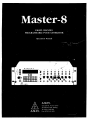
Master-8
EIGHT CHANNEL
PROGRAMMABLE PULSE GENERATOR
Operation Manual
A.M.P.I.
A.M.P.I.
123Uzlel St., P.O.B. 16477
Jerusalem 91163, ISRAEL
Tel: (972) 2 439 338
Fax: (972) 2 431 833
Thank you for buying Master-8 — the most flexible pulse generator. Master-8 is
an 8 channel pulse generator, based on advanced microprocessor technology.
Therefore Master-8 has many handy options. Please read this manual carefully
and become familiar with all the possibilities. You will find Master-8 friendly to
use and the programming simple and easy to learn. Master-8 is an attractive unit
and you will enjoy working with its eight paradigms.
On the following pages you will find:
Page 3 — Introduction
4 — Description of the keyboard, front and rear panels
5 — Operation
6 — Applications
7 — A demonstration of Programming Master-8
10 — Modes of operation
11 — Setting the parameters
13 — Triggering
14
14
15
16
—
—
—
—
17 —
20 —
21 —
22 —
23 —
Eight stored paradigms
Clearing the memory
Ways to check
The clock, stop-watch and timer
Master-8-cp, communication with a computer
APPENDIX A: The RS-232 connections.
APPENDIX B: Setting the baud - rate
APPENDIX C: The codes of the keys
APPENDIX D: Notes for programming Master-8-cp by
a computer.
Introduction
P r e p r o g r a m m e d settings
Master-8 is an 8 channel pulse generator. With Master-8 you can easily switch
your set-up between completely different experiments (paradigms). Master-8
stores eight user's preprogrammed paradigms. Each paradigm can use all the eight
channels. You can switch your set-up to the selected setting by a single command.
This option is very useful in the following cases:
a) When you want to switch the experiment to another one. The changeover is
very fast (50 msec).
b) When several users are using the same set-up. Each user recalls his settings
from the memory of Master-8.
All parameters of all the 8 paradigms are stored in the memory even after the power
is switched off by a lithium battery with a guaranteed life of 7 years. There is no
need to reinsert the parameters after switching on the unit.
Operation
Each channel operates independently in one of the following modes:
1. FREE-RUN— The channel delivers pulses continuously.
2. TRIGGER — Following a trigger, the channel delivers a single pulse.
3. TRAIN — Following a trigger, the channel delivers a train of pulses.
4. DC — DC output, time independent, turns on and off manually.
5. GATE (channels 1 and 2 only) — The channel delivers pulses continuously
while it is externally gated.
Each channel can be internally connected with different channels and receive
trigger pulses from them. There is no need to connect wires between channels.
The Master-8-cp model can be programmed by a computer via a standard
RS-232 interface. The communication is bidirectional.
Channels 1 & 2 can receive external triggers. This offers a possibility of
synchronizing those (and other) channels with external devices.
In addition to its standard 8 channels Master-8 features a clock that counts the
time that has passed from pressing the CLOC^K-RESET key (e.g. the experiment
time). It features a timer that can change the mode of a channel at a certain hour
(e.g. turn it on oroff).
The amplitude of the output pulses can be adjusted from -lOV to +10V, and
maximum current of 20 mA.
Description
T H E PO\X'ER S W I T C H is located on the lower left side of the front panel. Beside
it is a red light indicating 'POWER 0 N \
F r o n t panel keys
The front panel keys are divided into 5 groups. Each group has a different shade,
please follow:
1) The digits: 0 — y.
2) The operation mode keys: FREE (Free Run), T R A I N , T R I G , DC, GATE,
OFF.
3) The parameter keys: DURA (Duration), DELAY, I N T E R (Interval Time),
M (No. o[ pulses per train),' f , ' i '
-1) The clock keys: C L O C K - D I S P L A Y , S T O P - W A T C H , C L O C K - R E S E T ,
TIMER.
5) The command keys: C L E A R - D I S P L A Y , C 0 X N E C T / D I S C 0 N \ E C : T ,
C:HEC:K, ENTER, RESET.
Some of the keys have a dual function.
Pressing a key is followed by a response on the display. The code of the key
is written on the key. (For example: the code of FREE is 'FR').
Channel Board
On the right hand side of the key section is the external (EX'T) input section
divided into two parts—EXT 1 for channel 1 and E X T 2 for channel 2. Each has a
BNC socket and an O N / O F F switch for enabling and disabling the input.
'To their right is the eight channel control section. On the panel from the top down
arc: the channel number, a L E D indicating that the channel is active, a switch to
select the polarity of the output pulses, a knob to adjust the output amplitude, and a
BNC socket to connect the output to external devices.
Outputs '2-f 3\'4 + 5' and '6-(-7-i-8' are the summations of the outputs 2 + 3, 4-1-5 and
6 + 7 + 8 respectively. These sockets can be used for multilevel pulses (e.g. - - pulses). 'The two switches add the summations 2 + 3 and/or 6+7+8 to the '4 + 5'
output, thus the '4+5' output can deliver up to 7 levels pulses + CiND.
Rear panel
On the rear panel there is a switch to connect/disconnect the ground to/from
chassis. Sometimes this switch is used to reduce the noise level of the system.
In the M a s t e r - 8 - c p model (computer programmable) there is a RS-232 interface
for communication with a computer.
r
Operation
General
The operation of Master-8 is simple and can be learned in a short time. Previous
parameters remain in the memory even after the power has been switched off,
unless the parameters are changed.
Every instruction is carried out only after pressing the ENTER key. As long as the
ENTER key has not been pressed, the instruction can be changed or deleted by
giving new instructions (e.g. the CLEAR-DISPLAY instruction).
If a non-operable instruction is inserted, an error message appears on the display.
The unit does not accept this instruction and is ready to receive a new one.
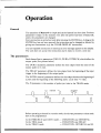
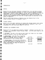
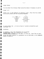
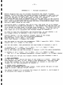
The parameters
Each channel has its parameters (DELAY, DURA, INTER, M) which define the
output pulse (See picture below).
The DURA (duration) parameter defines the time elapse from the onset of the
output pulse to its end.
The DELAY parameter defines the time elapse from the beginning of the input
trigger to the beginning of the output pulse.
The INTER (interval) parameter defines the time elapse between the beginning of
a pulse and the beginning of the following pulse, (cycle time = I/rate).
The M parameter is the number of pulses per train in the TRAIN mode.
I«-
Jl
X
Jl
delay
interval
duration
zn
R
Before operating a channel in a certain mode, the relevant parameters to that mode
have to be programmed:
In the FREE-RUN and GATE modes — DURATION and INTERVAL.
In the TRIG mode
— DURATION and DELAY.
In the TRAIN mode
— DURATION, INTERVAL and M.
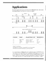
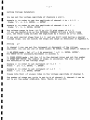
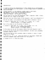
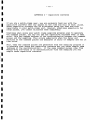
Applications
The following illustration gives you an idea of how M a s t e r - 8 works. Don't follow
the programming yet, you will do it in the next chapter.
duration
M=4
"L
#5-
Output 4+5; Bilevel pulses (out U4 + out flSj
CHANNEL
MODE
PARAMETERS IN USE
TRIGGERED BY
duration, interval
duration, delay
duration, intcival, M
none
none
-4
^5
I-RHl-.-RUN
TRIG
TRAIN
DC
none
Note.s for the figure:
® Triggered externally or manually (by one kcy.stioke).
© 'I'urned on and off manually (by one keystroke).
b) A special feature of M a s t e r - 8 is the 3 multilevel outputs: O U T P U T S '2+3',
'4+5', and '6+7+8' which deliver the summations of the outputs 2+3, 4+5 and
6+7+8 respectively. These outputs can be used for multilevel pulses (e.g. + / pulses). There are two switches to add the summations 2+3 and/or 6+7+8 to the
'4+5' output, thus the '4+5' output can deliver up to 7 level pulses + G N D .
The following are examples of outputs that you can get through the '4+5'
output;
R
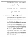
A Demonstration of Programming Master-8
This chapter is a demonstration of how to program the Master-8. Please follow the
instructions and notice how simple and straight-forward the instructions are.
Please note that each instruction is followed by the page number where you can
find more details on similar instructions. Before continuing, make sure that you are
familiar with the location of the different keys (see page 4).
The first step is to clear the entire memory of Master-8 —
Press: 'OFF, ALL, ALL, ALL, ENTER' (see page 14).
This instruction clears all paradigms of Master-8. Now we are ready to program it.
1) Set channel # 1 to the FREE-RUN mode, by pressing: 'FREE, 1, ENTER' (see
page 10). Channel #1 now delivers pulses continuously. Since we have not yet set the
time parameters, the channel is running with its default times: 0.1 sec duration and
0.2 sec interval (from the beginning of a pulse to the beginning of the next one).
2) Now let's set the duration time of channel #1 to 9.5 msec. The format of 9.5
msec, will be 9.5 x 10' sec. (or several other formats, see page II).
Press: 'DLIRA , 1' — The previous duration is displayed. Now you get the
'FFFF FF', since the duration time of channel #1 has never been set.
Now press: '9.5, ENTER, 3, ENTER'. ('3' for msec. For seconds use '0', For ^sec
use '6'). The duration of channel # 1 is now exactly 9.5 msec. (Please check with a
scope).
Now let's set the interval time of channel #1 to 2 sec. What do you have to press?
Press: 'INTERVAL, 1, 2, ENTER, 0, ENTER'. (The '0' is because you count in
seconds.) Now channeWl is running in the FREE-RUN mode. Its duration time is
9.5 msec, and its interval time is 2 sec.
3) Let's set channel #2 to the triggered mode.
Press: 'TRIG, 2, ENTER' (see page 10). and...nothing happens. Channel #2 is
now on the TRIGGERED mode, but is waiting to accept a trigger. You can
trigger it in 3 ways:
A) MANUAL TRIGGERING — Press: '2'. ('2' is the channel number.) Note
that each press on '2' delivers the triggered pulse. Press '2' several times.
B) EXTERNAL TRIGGERING — Whenever there is an input pulse in the
'EXT 2' input it triggers channel #2 (see page 13).
C) INTERNAL TRIGGERING — You can internally connect each channel to
any number of the other channels (see page 13).
(4) Let's connect channel #1 internally to channel #2 —
Press: 'CONNECT,!, 2, ENTER' and it is connected, (see page 13).
Each output of channel #1 triggers channel #2. You don't have to connect wires
between channels. You also don't have to worry about the amplitude or polarity of
the trigger source. Even the instruction itself is very straight forward (the same way
you would say it: 'CONNECT from #1 to #2, ENTER'). Please note that you can
add manual pulses by pressing '2'.
(5) Now set the duration of channel #2 to be 15 msec. —
Press: 'DURA, 2, 15, ENTER, 3, ENTER' (see page II).
(6) Set the delay of channel H 2 to be 100 msec. —
Press: 'DELAY, 2, 100, ENTER, 3, ENTER' (Please check the new delay).
(7) Let's set channel #3 to the train mode. What is the instruction?
Right! Do you see how simple it is?
Press: 'TRAIN, 3, ENTER'.
Channel #3 is now in the TRAIN mode and is waiting for a trigger.
(8) Trigger it manually several times by pressing '3' (see page 13).
(9) PULSES PER TRAIN
Set the number of pulses per train in channel #3 to be 5.
Press: 'M, 3, 5, ENTER, 0, ENTER' (see page 11).
Now trigger Channel #3 manually again by pressing '3'.
(10) Now connect channel #1 to trigger #3. What is the instruction?
Press: 'CONNECT, 1, 3, ENTER' (see page 13).
Channel #1 is now triggering both channels #2 & #3. Please note the'-»'sign on the
panel above the '1.3' digits. This arrow indicates the direction of the connection.
And now for the most powerful feautre of Master-8. Let's say that you
programmed all the 8 channels to run in a specitic pattern, which is your present
experiment. Now you want to switch to a new pattern (paradigm) that also uses all
the 8 channels. With Master-8 you can do this very easily. But first you have to
program the other paradigm .
(11) Press: 'ALL'
The name of the present paradigm (now '1') is displayed. In order to switch to
paradigm #5, Press: '5, ENTER' (see page 14).
Since this is a new paradigm all the channels are off, all the internal connections are
disconnected and all the time parameters have their default values.
(12) Set all the 8 channels to the FREE-RUN mode by pressing: 'FREE, 1,
ENTER', 'FREE, 2, ENTER', etc. Each of the 8 channels is now running
continuously at its own rate, independent of the other channels (Nice, isn't it?).
(13) Now you can switch back to the previous paradigm by recalling it.
Press: 'ALL, 1, ENTER' and you get the previous paradigm.
Press: 'ALL, 5, ENTER' and you get the other one. All the channels are now
working in synchronization since you initiated them together.
(14) What about turning the power ofP Let's try it. Turn the power off.
Master-8 stores all the 8 paradigms even when the power is turned off. There is a
lithium battery for memory retention. This lithium battery should be replaced only
after 7 years.
(15) Now turn the power on. Master-8 immediately continues working in the last
paradigm just as before you turned the power off.
(16) Switch to paradigm #1. Press: 'ALL, 1, ENTER'. Note that this paradigm is
also stored in the memory after turning the power off.
Dear User,
The last chapter was a brief demonstration of how to use Master-8. Now you have
some idea of how Master-8 works, but it is not enough. There are many
instructions that you are not yet familiar with e.g. DC, GATE, CHECK, TIMER.
Even the features that are demonstrated above are only partially demonstrated.
Please read the rest of this manual carefully so that you will not miss any important
feature. Pages 10-16 deal with the operation of Master-8. Pages 17-23 are about the
communication of Master-8-cp with a computer.
(17) Before continuing clear all the memory of Master-8 —
Press: 'OFF, ALL, ALL, ALL, ENTER', (see page 14).
Modes of Operation
Each of the 8 channels can operate in one of the following modes:
FREE RUN: The channel delivers pulses continuously according to the
programmed duration and interval times. The channel is independent of the other
channels.
TRAIN: Following a trigger, the channel delivers a train of pulses according to the
programmed duration and interval times. 'The number of pulses per train is
.set by 'M'.
TRIG: Following a trigger, the channel delivers a single pulse according to the
programmed delay and duration times.
DC: The channel delivers a DC pulse (time independent). The channel turns on
and off manually.
GATED: (available only on channels 1 and 2, the external gate is input through
EXT 1 or EXT 2). 'The channel delivers pulses continuously while it is externally
gated. When the external input stops, the channel stops working. A new input
reactivates the channel.
Before operating a channel in one of the modes, the relevant parameters to that
mode have to be programmed.
When on one of the modes 'TRAIN or 'TRIG the channel can be triggered by:
1) Manually.
2)'The internal connections.
3) EXT 1 (for channel 1 only) EXT 2 (for channel 2 only).
Setting the modes of operation
In order to set the mode of operation of a channel, first press the chosen mode key
then the channel number.
Example 1: In order to set channel #2 to the FREE-RUN mode —
Press: 'FREE, 2, ENTER'.
Channel #2 now delivers pulses continuously, according to the duration and
interval preprogrammed times (or the default times).
Example 2: In order to set channel #3 to the TRAIN mode —
Press: 'TRAIN; 3, ENTER'.
Channel ^3 is now on the TRAIN mode. There are several ways to trigger it.
Trigger it now manually by pre.ssing '3' (the channel number).
Example 3: In order to turn off channel #2 —
Press: 'OFF, 2, ENTER'.
Example 4: In order to turn off all the channels —
Press: 'OFF, ALL, EN'TER'.
101
Setting Parameters
In order to set the time parameters (DURA, DELAY or INTER), first press the
chosen parameter key then the time desired.
Example: In order to set the duration of channel 6 to be 52 msec (52x 10"^ sec, the
time is always given in seconds).
Press: 'DURA,6'. (The previous duration is displayed. If the duration time has
never been inserted, the sign 'FFFF F F ' is displayed).
Now press: '52,ENTER, 3, ENTER'. ('3' for msec)
Before pressing the ENTER key, you can change the instruction. The time is
accepted only after the last ENTER.
52 msec can be inserted also as 0.052x 10 sec, or 5.2x lO"" sec, or 5200x 10 sec, etc.
For your convenience it is recommended to use only exponents of 6 (|asec),
3 (msec) or 0 (sec). Thus for 52 msec use either 52 msec or 0.052 sec.
U s i n g t h e 'T' a n d ' l ' k e y s :
You can increase or decrease each time parameter using the ' t ' and ' 1 ' keys.
Example: Press: 'DURA, 6'. Now, prolonged presses on the 'T' and ' I ' keys
change the duration of channel 6. Please note that the change takes place only
after releasing the key.
Setting the 'M' parameter:
Example: To set M=80 pulses per train on channel 8, —
Press: ' M,8'. The previous M8 is displayed.
Now press: '80, ENTER, 0, ENTER.
Only integer numbers are accepted for M. The exponent should equal 1 only for
M > 9999.
Counting the pulses
Whenever channel 8 is in the TRAIN mode, the display shows how many pulses
still remain on the existing TRAIN.
Press: 'TRAIN, 8, ENTER'.
Now trigger channel 8 manually by pressing: '8'.
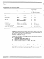
Table 1
P a r a m e t e r s and e r r o r indication
Hrror indication
Min
Max
for illegal values.
(x is the channel number)
1. M
59,990
Mx
Err
2. D U R A T I O N
40|isec
3999 sec
Dx
Err
3. DELAY
lOO^sec
3999 sec
DELAY>L>URATION/10,000
Lx
Lx
Err
Err
4. I N T E R V A L
a) Normal usage:
b) Train mode:
c) If the channel internally
activates other channels:
60nsec
3999 sec
INTERVAL>DURATION+9liSeC
INTERVAL>DURATION + 59|aseC
Ix
Rx
Tx
Err
Err (Rate err)
Err (Train err)
INTERVAL >500|iSeC
Cx
Err (Connect err)
E x a m p l e : T h e message ' R 7 E r r ' indicates ' R a t e e r r o r ' on channel #7.'The reason
is that the c h a n n e l is now r u n n i n g on F R E E - R U N , G A T E or T R A I N m o d e , a n d
t h e interval is shorter t h a n the d u r a t i o n or at least
INTERVAL < DURATION + 9 | i s e c .
I n o r d e r to get rid of the R7 E r r message you should move o u t of this situation in
one of the following ways:
a) increase the interval time of c h a n n e l #7.
or b) decrease the d u r a t i o n time of c h a n n e l #7.
or c) change the m o d e of c h a n n e l #7 to T R I G , D C or O F F .
Please note that there is no delay in the T R A I N m o d e . T h e channel delivers the
train of pulses immediately after receiving the trigger i n p u t . I n o r d e r to get a
delay t i m e , you should use an i n t e r m e d i a t e channel in the ' T R I G m o d e .
12i
Triggering
Manual triggering
In the modes: TRAIN, TRIG, or DC the channel can be triggered manually.
Example 1: When channel 3 is on the TRAIN mode, every press on the ' 3 ' key,
evokes u train of pulses according to the parameters of channel 3.
Example 2: When channel 4 is on the DC mode, every even press '4' turns the
channel on, and every odd press turns it off.
When a channel is not in one of the above modes, or if it has already received a
trigger but has not yet completed its response, pressing the channel number does
not affect the channel (It just clears the display).
Setting the internal connections:
In the modes TRAIN or 'TRIG the channel can be triggered by other channels
internally. Each channel has an internal input and an internal output. By inserting
the right instructions, you can connect an internal input to an internal output.
Example 1: In order to connect the output of channel 2 to the input of channel 3 —
Press: 'CONNECT, 2, 3, ENTER'.
The arrow above the display shows the direction of the connection. For example,
2.3 means that the output of channel 2 is connected to the input of channel 3.
Every internal output can be connected to any number of internal inputs. Every
internal input can be connected to any number of internal outputs. The level or
polarity of the output does not affect the internal connections.
Disconnecting is performed by pressing the 'CONNECT' key twice.
Example 2: In order to disconnect an existing connection between 2 and 3 —
Press: 'CONNECT, CONNECT, 2, 3, ENTER'.
It is possible to disconnect all inputs or outputs of any single channel.
Example 3: To disconnect all outputs from channel 5 —
Press: 'CONNECT, CONNECT, 5, ALL, ENTER'.
Example 4: To disconnect all inputs to channel 5 —
Press: 'CONNECT, CONNECT, ALL, 5, ENTER'.
Example 5: 'To disconnect all inputs and all outputs of all channels —
Press: 'CONNECT, CONNECT, ALL, ALL, ENTER'.
The external inputs
In the modes: 'TRAIN, 'TRIGorGA'TE channels 1 and 2 can be triggered (gated)
externally. EX'T 1 activates only channel 1. EXT 2 activates only channel 2.
(channels 1 and 2 can activate the other channels internally).
'The external input has to be in the range of 5-10 V.
Please note that a computer can trigger each channel directlv 'manually' via the
RS-232 interface of Master-8-cp (see page 17).
13
^ =
Eight Stored Paradigms
A paradigm specifies the modes and parameters of all the channels and their
internal connections. Master-8 stores eight different programmed paradigms.
The changeover from one paradigm to another is very fast (50 msec).
Transferring to another paradigm
Example: To transfer to paradigm number 7 — Press: 'ALL' (the previous
paradigm is displayed) '7, ENTER'.
You don't have to worry about saving the old paradigm. Each instruction is saved
the moment you insert it.
NOTE: Transferring from one paradigm to another does not affect the clock, the
stop-watch or the timer.
Copying paradigms
Copying paradigms is very useful when you want a new paradigm with just some
changes from a present one. Instead of programming the whole new paradigm, you
can copy the present one and just make the changes.
Example: In order to copy paradigm #2 to paradigm #6 —
Press: 'ALL, 2, 6, ENTER'. (Please note the arrow sign ('-»') for the sourcetarget direction). Paradigm #2 is not affected by this instruction.
Clearing the memory
In order to turn off all the channels — Press: 'OFF, ALL, ENTER'.
In order to disconnect all the internal connecfions (in the present paradigm) —
Press: 'CONNECT, CONNECT, ALL, ALL, ENTER'.
In order to clear all the memory of the present paradigm —
Press: 'OFF, ALL, ALL, ENTER'. This will turn off all the channels, disconnect
all the internal connections, and change all the parameters of all the channels to the
initial values 'FFFF FF'.
NOTE: Clearing the present paradigm does not affect the other paradigms, the
clock, the stop-watch and the timer.
In order to clear all the memory of all the 8 paradigms (and Master-8 will then be
without any user program)
Press: 'OFF, ALL, ALL, ALL, ENTER'.
^ ^ S ^ 14
— ^ ^ — ^ ^ ^ = ^ =
^ ^ ^ i ^ =
Ways to Check
There are many details you can check. All the checking instructions begin with the
word 'CHECK'.
1) To check the modes of all the channels —
Press: 'CHECK, ENTER'.
The display shows the modes of all the channels that are not turned off and the
present paradigm number.
2) To check the mode and the parameters (DURATION, DELAY, INTERVAL
and M) of a specific channel (e.g. channel 2) —
Press: 'CHECK, 2, ENTER'.
You can check (and change) each parameter individually, as described above (in
'setting parameters'. Page no. 11 )•
3) Checking the internal connections:
Example 1: To check which inputs are internally connected to the output of
channel 4 —
Press: 'CHECK, 4, CONNECT, ENTER'.
If channel 4 does not have any output connections this instruction just clears the
display.
Example 2: To check which outputs are internally connected to the intput of
channel 7 —
Press: 'CHECK, CONNECT, 7, ENTER'.
Note the arrow above the display shows the direction of the connections.
Example 3: To check all the internal connections —
Press:
'CHECK, CONNECT, CONNECT, ENTER', (or: 'CHECK,
CONNECT, ENTER').
15s
Clock Options
In addition to its standard 8 channels, M a s t e r - 8 features 2 internal clocks. The
first is called 'clock' and counts the time in seconds up to 24 hours. The other called
'stop-watch' counts the time by tenths of seconds up to 1 hour.
The clock
'The clock is used:
1) to measure the time that passed from an event (e.g. the beginning of the
experiment).
2) for the ' T I M E R ' option (see below).
'The clock time can always be displayed by pressing the ' C L O C K - D I S P L A Y ' key.
T h e clock can be reset by pressing the ' C L O C K - R E S E T ' key. The resetting can be
performed only w h e n t h e clock t i m e is d i s p l a y e d .
The clock never stops running. A second press on ' C L O C K - D I S P L A Y ' (or any
other key except the 'CLOCK-RESE'T' key) clears the clock display.
The stop-watch
The first press on the 'S'TOP-WATCH' key displays its present situation. 'Then
every odd press activates it and every even press stops it.
The stop-watch can be reset by the ' C L O C K - R E S E T ' key only w h e n t h e s t o p w a t c h t i m e is d i s p l a y e d .
N O T E : 'The main ' R E S E T ' key resets both clocks, regardless of what was shown
on the display.
The timer
'The 'TIMER is linked to the clock and can change the mode of any single channel at
a fixed time. For example, if you want to set the experiment to stop at a given time
you can instruct one channel (or all of them) to do so.
E x a m p l e 1: In order to turn off channel til at 3:45 (as counted by the clock).
P r e s s : ''TIMER, EN'TER'. Now the timer shows its last setting (if no instruction
was inserted, it shows ' O F F ' ) .
Now P r e s s : ' O F F , 2, E N T E R , 3, E N T E R , 45, EN'TER'.
C:heck by pressing: ' T I M E R , ENTER'.
'To exit from the TIMER checking, press the C L E A R - D I S P L A Y key.
E x a m p l e 2: If the T I M E R is already set and you want to cancel the 'TIMER
action, you can turn the 'TIMER off by pressing: ''TIMER, O F F , EN'TER'.
16i
Master-8-cp
P r o g r a m m i n g by a computer
Master-8-cp can be programmed through the front panel keys in the same way as
Master-8. In addition Master-8-cp can be programmed via a computer or even
by a terminal consisting of a monitor and a keyboard.
In order to communicate with a computer, you should connect the Master-8-cp to
the computer via the standard RS-232 interface on the rear panel. The connections
are described in Appendix A.
Master-8-cp can receive and transmit ASCII characters. The setting of the
communication parameters i.e. baud-rate and the character-format is very simple
(See Appendix B).
Communication
A. PROGRAMMING Master-8-cp BY A COMPUTER
Programming Master-8-cp via a computer is identical to programming it via the
front panel keys. Each key has a corresponding code (see Appendix C). Sending the
code by the computer has the same effect as pressing the specific key.
Example I: The instruction: 'FREE, 3, ENTER' (meaning set channel #3 on the
FREE-RUN mode) is performed by the computer writing 'F 3 E' to Master-8-cp.
(See Appendix C).
Example 2: The instruction: 'DURA, 2, 1.4, ENTER, 3, ENTER' ("set the
duration of channel #2 to be 1.4 msec") is performed by the computer writing —
'D 2 1.4 E 3 E' to Master-8-cp.
In fact, Master-8-cp does not distinguish whether a certain instruction was
inserted via the keys or via the computer (except for the CHECK instruction, see
below).
Please note that the computer can trigger each channel 'manually'.
Example 3: When channel #8 is on the TRIG or TRAIN mode, you can trigger it
manually by pressing the '8' key. The computer can also trigger channel #8
manually by writing '8' to Master-8-cp.
B. COMMUNICATION FROM Master-8-cp TO THE COMPUTER.
The communication from the computer to Master-8-cp does not need any initial
or final codes. Master-8-cp is always 'listening' to the computer. However, in the
communication from Master-8-cp to the computer, the computer has to send
codes indicating that it is ready to accept information. Otherwise its internal buffer
will fill with insignificant information.
Whenever the computer is ready to receive information, its program has to send to
Master-8-cp the initial code 'B 1 E' (meaning B=l, ENTER). To stop the flow of
informafion, the code 'B 0 E' (B=0) should be sent to Master-8-cp. While B=l,
Master-8-cp transfers all the information that appears on the front panel display
to the computer.
When Master-8-cp accepts a CHECK instruction, it recognizes whether it was
sent by the front panel keys or by the computer. If it was sent by the keys Master8-cp waits a while after displaying each parameter. If it was sent by the computer
Master-8-cp does not wait at all, and sends the suitable information to the
computer. In the case of the CHECK instruction, Master-8-cp sends information
even when B=0.
You have to take special care when you send the CLOCK or STOP-WATCH
information to the computer, because this information is running confinuously and
can easily fill internal buffers of the computer. Whenever you want to read such
information from Master-8-cp, send the letters 'B 2 E' (B=2), read the
information and immediately set back to B=0 or B=l.
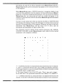
The instruction 'H X E' (checks all the internal connections, like 'CHECK,
CONNECT, ENTER') invokes Master-8-cp to send a table of all the internal
connections to the computer as follows:
1 2
1
3
4
+
+
5
6
7
+
+
8
2
3
4
5
6
7
8
'*' — Symbolizes that there is an operational connection between the two channels,
i.e. there is a connection between them, and it fulfills the following conditions:
a) The target channel is in one of the modes TRIG or TRAIN (the modes in which
the channel expects a trigger input).
b) The source channel is not in the OFF mode. (Thus it may send a trigger).
In the table there is an operational connection from channel #2 to channel #5.
' + ' — symbolizes that there is a connection that is not operative between the two
channels. In the above table all the internal outputs of channel # 1 are not operative.
18i
The instruction 'H A E' ('CHECK, ALL, ENTER') transfers to the computer (or
monitor) all the information about the present paradigm, (the table of the
connections, the modes and parameters of all the channels).
See Appendix D for some examples of communication with a computer.
Communication between Master-8-cp and a terminal
The communication between Master-8-cp and a terminal (monitor and
keyboard) is identical to the communication with a computer, but it is
recommended to insert the initial code 'B 1 E' at the beginning of the
communication (without the final code 'B 0 E').
In this case Master-8-cp sends all the information that appears on its display to
the monitor. The instrucfion 'H X E '('CHECK, CONNECTIONS, ENTER')
causes Master-8-cp to send the connections-table to the monitor as described
above. The instruction 'H A E' sends all the parameters of the present paradigm,
including the table of connections.
19i
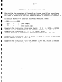
Appendix A
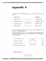
For minimum system interconnection, pins no. 1, 2, 3, 7 should be connected as
follows:
Computer
Master-8-cp
1 CHASSIS GND
CHASSIS GND
2
TRANSMIT DATA
TRANSMIT DATA
3
RECEIVE DATA
RECEIVE DATA
7
SIGNAL GND
SIGNAL GND
A jumper should be connected between pins no. 4 and 5 (CTS,RTS) on the
connector in the Master-8-cp side.
For a regular connection, pins no. 1,2, 3,7 should be connected as described above,
without the jumper between pins 4 and 5. In addition pins no. 4, 5,6,20 should be
connected as follows:
4
RTS (request to send)
RTS
5
CTS (clear to send)
CTS
6
DSR (data set ready)
DSR
DTR
20 DTR (data terminal ready)
The RS-232 connector:
13
25
20i
Z^
14
Appendix B
Setting the baud-rate and character format
1) A double press on the ALL key shows the present baud rate. Each additional
press on the ALL key selects the next baud-rate in the cycle:
75,110,150,200,300,600,1200,2400,4800,9600,19200.
2) Pressing the EN'TER key latches the selected baud-rate.
3) BITS PER CHARACTER: Each press on the ALL key selects either 7 or 8 bits
per character (ASCII).
4) Pressing the ENTER key latches the number of bits per character.
5) PARITY BTT: Each press on the ALL key selects the next parity mode in the
cycle: 0 — no parity. 1 — odd parity. 2 — even parity.
6) Pressing the EN'TER key latches the selected parity.
7) STOP BTTS: Each press on the ALL key selects either 1 or 2 stop bits.
8) Pressing the EN'TER key latches the selected number of stop bits.
9) Press: CLEAR-DISPLAY.
Check that you selected the right setting by pressing: —
CHECK, ALL, EN'TER.
21
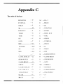
Appendix C
The codes of the keys
DURATION
—D
A,9
—ALL, 9
INTERVAL
—I
B
— BEGIN
DELAY
—L
C
— DC
M
—M
D
— DURATION
FREE-RUN
—F
E
— ENTER
TRAIN
—N
F
— FREE - RUN
TRIG
—G
G
— TRIG
DC
-
H
— CHECK
GATE
—T
I
— INTERVAL
OFF
— 0
L
— DELAY
0, TIMER
— o,w
M
—M
1-8
— 1-8
N
-
9,A11
-9,A
O
— OFF
b
— '.'
Q
— CLOCK DISPLAY
R
— CLOCK RESET
1
C
CLOCK DISPLAY - Q
TRAIN
STOP-WATCH
- s
S
— STOP-WATCH
CLOCK RESET
—R
T
— GATE
CHECK
—H
W,0 — TIMER, 0
CLEAR DISPLAY
— \'
X
— CONNECT
CNCT/DSCNCT
- X
\'
— CLEAR DISPLAY
DISCOXNl-:CT
— /
z
— DISCONNEC:T
ENTER
— 1-:
1-8
— 1-8
BEGIN
—B
i
1
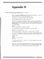
Appendix D
Notes for programming the Master-8-cp by a computer
When programming Master-8-cp through your own program, you have to
program the RS-232 communication parameters first.
For example the instruction (BASIC], IBM compatibles):
OPEN "COM1,9600,N,8,1,CS,DS,LF,PE" AS #1
tells the PC to communicate at baud rate 9600, no parity, 8 bits per character, 1
stop bit and suppress the control lines. From now on the computer refers to
Master-8-cp as #1. Now, to operate channel 3 on the FREE-RUN mode, you can
use the instruction:
PRINT #1,"F 3 E";
which is the equivalent to 'FREE, 3, ENTER'.
'To set the duration of channel 3 to 250 msec, use the instruction:
PRINT #1, "D 3 250 E 3 E";
which is the equivalent to 'DURATION, 3, 250, ENTER, 3, ENTER'
One can also use variables. The following is an example of programming the delay
of channel 1 to be 100 msec, delay 2 to be 200 msec, delay 3 to 300 msec. etc.
FOR 1=1 'TO 8
J=100*I
PRINT #1,"L";IJ;"E 3 E";
NEXT I
'The instruction PRINT #1,"L"IJ;"E 3 E"; has the meaning: Set the delay
of channel I, into J msec.
When you switch between paradigms please note that the changeover takes a
while. 'Thus after the instruction to switch to a new paradigm, you should make a
break of 100 msec in your program before giving a new instruction.
«iJ—jfj^t'wXj^jaaMS'"~'BI * *
-'-'*! • " T — ' ^ V
|«ia>ocHUM|
cflnvfir
^yimr'^-^i0^i^
t
.a/SsmuMdy
mm:
A
A.M.P.I.
A.M.P.I.
123UzielSt., P.O.B, 16477
Jerusalem 91163, ISRAEL
Tel: (972) 2 439 338
Fax: (972) 2 431 833
[/c^
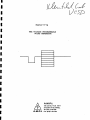
Master-8-vp
THE VOLTAGE PROGRAMMABLE
PULSE GENERATOR
A.M.P.I.
A.M.P.I.
123UzielSt.. P.O.B. 16477
Jerusalem 91163, ISRAEL
Tel: (972) 2 439 338
Fax: (972) 2 431 833
- 1-
In this manual we assume that you have already read the manual of Master-8.
Thus, it describes only the features of Master-8-vp that Master-8 does not
have.
If you are an experienced user of Master-8 you probably know that Master-8
is a very flexible unit. Master-8-vp adds this flexibility in the fields
that require increment/decrement voltage steps.
Using the FIXED STEPS or the VARIED STEPS modes, in combination with the
different modes of operation: FREE-RUN, TRIG, TRAIN, GATE and DC, and
setting the 8 channels to synchronize the voltage steps with many other
instruments, make Master-8-vp a very effective and powerful tool in your lab.
On the following pages you will find:
Page 2
3
6
6
6
7
9
10
11
12
-
Introduction
Setting Parameters
Output Offset
Output '4+5'
Parameters
Demonstration
Appendix A: Higher Voltage Resolution
Appendix B: Voltage Calibration
Appendix C: Capacitive Currents
Appendix D: Communication With a PC
- 2 INTRODUCTION
General
Master-8-vp has the same features as Master-8-cp. You can easily switch
between 8 preprogrammed paradigms (in order to switch between different
experiments) using a single command. You can set all parameters using the
front panel keys or via the RS-232 interface. You can also run the
channels in the following modes: FREE-RUN, TRIG, TRAIN, DC and GATE and
have the same parameters and time and voltage ranges as described in the
manual of Master-8.
The only additional feature of Master-8-vp over Master-8-cp is the
output voltage control of channels 4 and 5.
VOLTAGE CONTROL
While in all the other channels you adjust the voltage output level using
the front panel knobs, the voltage amplitudes of channels 4 and 5 are
programmed via the front panel keys or via a PC.
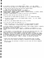
INCREMENT AND DECREMENT STEPS
Master-8-vp has an additional powerful feature - Channel 5 can be set to
increment or decrement output voltage steps. You set these steps in one
of three modes:
1) No steps - You set AV=0 and you don't have any steps (all the output
pulses of channel 5 have the same amplitude).
2) Fixed steps - You set the A V and the
number of steps per cycle. The number of
steps is unlimited. The only limit is
the saturation of the voltage range.
3) Varied Steps - You set each individual
step and the number of steps per cycle. You
can mix depolarizing and hyperpolarizing
steps. The number of steps is limited to
30 steps per cycle.
fixed steps
varied steps
- 3 Setting Voltage Parameters
You can set the voltage amplitude of channels 4 and 5.
Example 1: In order to set the amplitude of channel 4 to - 2.3 V
Press: 'V , 4, 2.3, ENTER, -, ENTER' .
-
Example 2: In order to set the amplitude of channel 5 to 1 V
Press: 'V , 5, 1, ENTER, ENTER' .
The voltage range is from -12.7V to +12.7V with steps of 0.1 V.
(If you use Master-8-vp as the EXTERNAL COMMAND driving a Patch Clamp
unit, the Patch Clamp divides the amplitude by a factor of 10 to 1000).
If you want smaller steps than O.l V, and you don't mind having a smaller
voltage range, you can modify the steps and range as described in Appendix A.
Setting
AV
In channel 5 you can set the increment or decrement of the voltage
amplitude. You can use one of three modes: NO STEPS, FIXED STEPS or VARIED ST
1) NO STEPS mode - Set A V = 0 by pressing: ' A V, 0, ENTER, ENTER'.
Now there is no increment/decrement in channel 5.
2) FIXED STEPS mode - Set the A V to the desired value and set the number
of steps per cycle. The number of steps is unlimited. The only limit is
the saturation of the voltage range.
Example 1: In order to set decrement of -0.3 V
Press: ' A V , 0.3, ENTER, -, ENTER'.
Example 2: In order to set increment of 1.2 V
Press: ' A V, 1.2, ENTER, ENTER'
Please note that
A V always rides on the voltage amplitude of channel 5.
The number of steps per cycle is set by M of channel 5. Channel 5 can be
set to all the modes :FREE-RUN, TRIG, TRAIN, DC and OFF.
- 4 Example 3: If V5=2, M5=4 and
the
the
the
the
1st
2nd
3rd
4th
pulse
pulse
pulse
pulse
=
=
=
=
AV=0.5 then:
2.5V
3V
3.5V
4V
Channel 5 delivers its pulses using the time parameters (DURATION,
INTERVAL and DELAY) the same way as the other channels do. The only
difference is the increment/decrement steps.
In the above example it is interesting to understand what channel 5 does
in each of the different modes of operation:
TRAIN
TRIG
: Following each trigger channel 5 delivers the above 4 pulses.
: Following each trigger channel 5 delivers the next pulse in the
above cycle. If there is a trigger after the last pulse, the
cycle starts again.
FREE-RUN: Channel 5 generates pulses continuously. The amplitude of the
pulses varies in the above cycle. After the last pulse the cycle
starts again.
DC
: The channel is time independent. The first time that you press '5'
(manual trigger) the channel delivers a DC output with the first
amplitude (2.5V in the example). The next '5' terminates the DC
output. The next ' 5 ' delivers the 3V DC output and the next
one terminates it, etc.
Channel 5 (as every other channel) can be triggered:
1) Internally, by another channel through the internal connections.
2) Manually, by pressing '5' ( - the channel number).
When you want to trigger channel 5 by the computer you can do it in one
of the following ways:
1) The computer triggers channel 1 (or 2) via the 'EXT 1' ('EXT 2') input.
Internally connect channel 1 to trigger channel 5. Channel 1 can also
be used to trigger the oscilloscope, recorder, etc.
2) 'Manually' by the computer: The computer sends the letter '5' ( - the
channel number) via the RS-232 interface.
For most applications you may use channel 5 in the TRIG or TRAIN modes and
the trigger comes from the computer, from another channel or manually. In
the demonstration of page 7 please find examples of such applications.
- 5 -
2) Varied Steps - You set each individual step and the number of steps
per cycle. You can mix depolarizing steps with hyperpolarizing steps. The
number of steps is limited to 30 steps per cycle.
Example 1: In order to set 4 pulses per cycle: the first step -8.5V, the
second -5V, the third -2V and the fourth +2V:
1) Set M of channel 5 to 4 by pressing: ' M, 5, 4, ENTER, ENTER'.
2) Set V5=0 by pressing: ' V, 5, 0, ENTER,ENTER'.
3) Set the VARIED STEPS by pressing: ' A V , ENTER'
Now press: '8.5, ENTER, -, ENTER'
(first pulse -8.5V)
and continue: '5 , ENTER, -, ENTER,
(second pulse -5V)
'2 , ENTER, -, ENTER,
(third pulse -2V)
'2 , ENTER, ENTER'
(fourth pulse +2V)
Please note that by this instruction you set the different step levels,
but you still haven't switched to the VARIED STEPS. Thus you still get the
FIXED STEPS.
4) Switch to- the VARIED STEPS by pressing: ' A V , OFF, ENTER'.
If you want.to switch back to the FIXED STEPS, set the desired increment/
decrement step again.
NOTE:
When A V = OFF - Master-8-vp uses the VARIED STEPS.
When A V = Value - Master-8-vp uses the FIXED STEPS.
When A V = 0 - Master-8-vp doesn't have any steps (but delivers pulses
with constant amplitude = V 5 ) .
- 6Output Offset
You can adjust the voltage offset using the knobs of channels #4 and #5.
Output '4+5'
Output '4+5' is the summation of channels 4 and 5. Thus from this output
you can get pulses like the following examples:
n
n
In each example the
individual AV.
AV can be fixed or varied by presetting each
Parameters
In Channels 4 and 5 the parameters are as follows:
Voltage range: from -12.7 volt to +12.7 Volt.
Interval time of Channel #5; 500 usee, to 3,999 sec. (more then an hour)
In all the other channels all parameters are as described in the OPERATION
MANUAL of Master-8.
- 7 Demonstration
In order to follow the demonstration in this chapter use an oscilloscope.
In this demonstration we use channel 1 as the trigger source to channels 4 an
and to the scope.
Connect channel 1 to the external trigger input of the scope.
Set channel 1 to run with the following parameters:
FREE-RUN mode, D1=0.1 m s e c , 11=500 msec.
Check that channel 1 now triggers the scope.
Set the scope to run with the parameters: TIME: 1 msec/div, GAIN : IV/div.
Connect the '4+5' output to the scope.
Make sure that the offset knobs of both channels 4 and 5 are adjusted to 0.
Now set the modes, time parameters and amplitudes of channels 4 and 5:
1) Channel 4: TRIG mode, D4 = 0.5 m s e c , L4 = 2 m s e c , V4 = 1 Volt.
Connect channel 1 to trigger channel 4.
Now on the scope you see the pulses of channel 4.
2) Channel 5: TRIG mode, D5 = 4 m s e c , L5 = 15 m s e c , V5 = -2V
and A V = 0 (no increment/decrement)
Connect channel 1 to trigger channel 5.
On the scope you now get the outputs coming from both channels 4 and 5.
So far we set the timing and voltage parameters. You don't get increment/
decrement steps as A V = 0 .
Now lets say that we want increment steps in channel 5, using
steps of 0.5 V each:
6
fixed
3) Set M5 = 6, A V = O.SV . Watch the results on the scope. Please note
that the increment steps ride on the V5 (= -2V) pulse.
4) Change to V5 = 0. Watch the scope.
- 8 5) In order to switch to the VARIED STEPS, Press: ' AV ,OFF, ENTER'
You don't see any steps as all the steps now have their default value = 0.
6) Now lets say that we want the following VARIED STEPS:
-4V, -2V, -IV, -0.5V, +2V, +4V .
In order to set these steps press: ' AV, ENTER'
Now Master-8-vp is ready to get the different steps.
Press:'4,ENTER,-,ENTER, 2,ENTER,-,ENTER, 1,ENTER,-,ENTER, 0.5,ENTER,-,ENTER,
2,ENTER,ENTER, 4,ENTER,ENTER' .
Now press: 'CLEAR DISPLAY' In order to exit out of the sequence.
Watch the scope and see that you get the varied
7) Switch back to FIXED STEPS by setting
AV.
AV = 0.5V, Watch the scope.
8) In order to switch back to the VARIED STEPS, Press: ' AV, OFF, ENTER'.
Watch the scope.
9) Set V5=1V, The VARIED STEPS ride on the IV pulses.
10) If you don't want any steps set A V = 0.
* Please note that it is very convenient to switch between NO STEPS
( AV=0) ,FIXED STEPS ( AV=any value), and VARIED STEPS ( AV=OFF).
12) So far channel 1 is running continuously. Lets trigger channel 1 manually
Set channel 1 to the TRIG mode.
Now each time that you trigger channel 1 (manually, by pressing ' 1 ' , or
through the PC via the 'EXT 1' input) you get the next trace in the above
cycle.
13) Set channel 1 to the TRAIN mode. Set Ml=6 (Ml should be equal M 5 ) . Now
each time that you trigger channel 1 you get the whole cycle.
Please note that in this example Ml counts the number of pulses per train
of channel 1 which is the number of pulses per cycle. M5 counts the number
of different amplitude levels in the cycle. Usually Ml should be equal to
M5. It may happen that the pulses of 'OUT 5 ' do not start from the first
pulse. In this case press: ' TRIG, 5, ENTER' to restart the pulses.
* Please note that different paradigms store different sets of steps.
Thus you can also change the steps by transferring between paradigms.
* When you copy one paradigm to another you also copy the entire sequence
of the steps.
- 9 -
APPENDIX A - Higher Voltage Resolution
The voltage range of channels 4 and 5 is from -12.7 V to +12.7V. with
resolution of O.IV. This range and resolution are suitable to patch clamp
units as the patch clamp divides this output by a factor of 10 to 1000.
However, if you want a finer resolution, you can double it, by dividing
the output of the channel by a factor of 2. This gives a resolution of 0.05 V
but changes the whole range to -6.35 V to 6.35 V.
You should keep in mind that Master-8-vp does not know that you made this
change. Thus, after switching, if you want an output of 1 V, you should
set the channel to a 2 V output.
In order to divide the output, open the top cover, and find 2 small red
DIP switches on the rear side of the circuit board. The one to your left
relates to channel 4 and the one to your right relates to channel 5. If
you didn't make any changes, both switches are in the OFF position, and
the output is not divided. In order to divide the output of channel 4 by
a factor of 2, set the left switch to ON. In order to divide the output of
channel 5 by a factor of 2, set the right switch to ON. Now you may have
to adjust the zero level and calibrate the output voltages as described in
Appendix B.
- 10 -
APPENDIX B
-
Voltage Calibration
Before shipping the unit we already calibrated the output voltages.
However, if you find that the output voltage of channels 4 and 5 are not
accurate, you can calibrate them. First check that the offset knobs of
those two channels on the front panel are set to 0 offset.
Now remove the top cover of Master-8-vp. On the rear part of the circuit
board, find 4 trim-potentiometers (trimpots). These trimpots are blue or
gray. They protrude above the surface and have a rectangular shape. Each
one has a small screw on its side.
Concerning these 4 trimpots: The one to your left side (A) is to adjust
the zero level of pulses from channel 4. The second one from the left (B)
is to adjust the zero level of pulses from channel 5. The third from the
left (C) is to calibrate the voltage output of channel 4 and the one to
your right (D) is to calibrate the voltage output of channel 5.
In order to make the adjustments and calibrations, we use channel 1 as
the trigger source to channels 4 and 5 and to the scope:
Connect channel 1 to the external trigger input of the scope.
Set channel i to run with the following parameters:
FREE-RUN mode, D1=0.1 m s e c , 11=500 msec
Check that channel 1 triggers the scope.
Set the scope to run with the parameters: TIME: 1 msec/div, GAIN : IV/div.
Connect the '4+5' output to the scope.
Now set the modes, time parameters and amplitudes of channels 4 and 5:
1) Channel 4: D4 = 1 m s e c , L4 = 3 m s e c , V4 = 1 V, Mode 4 = TRIG.
Connect channel 1 to trigger channel 4.
Now on the scope you see the pulses of channel 4 with the above parameters.
2) Channel 5: D5 = 4 m s e c , L5 = 5 m s e c , V5 = 1 V, Mode 5 = TRIG.
Set AV = 0 (no increment/decrement).Connect channel 1 to trigger channel
On the scope you now get the outputs coming from both channels 4 and 5.
3) ZERO ADJUSTMENT:
Now set V4=0, V5=0. Switch the gain of the scope to 0.IV/div. Check that
both outputs are zero. If not, using a fine screwdriver, turn the screw
on the left trimpot (A) for zero adjustment of channel 4, and that of
trimpot (B) for zero adjustment of channel 5.
4) OUTPUT LEVEL CALIBRATION:
In order to calibrate the voltage output, first switch the gain of your
scope to 2V/div, and set V4=12V, V5=12V.
Now adjust trimpot C to calibrate the output of channel 4, and trimpot D
to calibrate the output of channel 5.
- 11 -
APPENDIX C - Capacitive Currents
If you are a patch-clamp user, you are probably familiar with the
capacitive currents that may appear at the rise and fall of each pulse.
These capacitive currents may be eliminated using the fast and slow
capacitance in your patch-clamp unit. However, sometimes especially for
large pulses, you cannot eliminate them completely.
Sometimes when using your patch clamp sampling program also to generate
the command pulses, you may not see the capacitive currents even if they
exist. This may happen because of the synchronization between the command
pulses and the sampling. This occurs especially when the delay and
duration of the command pulses are measured in units of samples and not in
time units.
Thus, when the command pulses are generated from the sampling program it
is possible that there are capacitive currents but you never sample them
(because of the synchronization). If the same command pulses come from
Master-8-vp and there is no synchronization with the sampling you may
sample those capacitive currents.
- 12 -
APPENDIX D - Communication With a PC
When setting the parameters of Master-8-vp through your PC you should send
ASCII codes of letters instead of pressing keys. The codes are the same as
the codes of Master-8-cp. See the operation Manual of Master-8-cp Appendix C.
In addition Master-8-vp uses the following additional codes:
key
'AV
'V
I —I
code
-
J
V
(for jumps)
"(the minus,sign)
Example 1: The instruction (from panel keys): 'V, 5,
(meaning V5=-3V) is performed by the computer writing
3, ENTER, -, ENTER'
'V 5 3 E - E'.
Example 2: The instruction : ' V, 4, 2.1, ENTER, ENTER'
(meaning V4=2.1V) is performed by the computer writing 'V 4 2.1 E E'.
Example 3: The instruction ' AV, 1, ENTER, -, ENTER' ( AV=-1V) is performed
by the computer writing 'J 1 E - E'.
Example 4: The instruction ' AV, OFF, ENTER' ( AV = OFF, Switch to VARIED
STEPS mode) is performed by the computer writing 'J O E'.
A.M.P.I.
123UzielSt„ P.O.B. 16477
Jerusalem 91163, ISRAEL
PHONE: +972 2 643-9338
FAX:+972 2 643-1833
e-mail: [email protected]
http://www.ampi.co.il
\
Please note our new numbers: \
Phone: +972 2 643-9338
\
Fax:+972 2 643-1833
March 16,199/
Dear Doctor,
Thank you for buying Master-8 - the most flexible pulse generator. Enclosed please
find two manuals. Read them carefully and become familiar with the flexibility of
Master-8. The programming is friendly and easy to learn. I am sure that you will find
Master-8 an attractive unit and you will enjoy working with its eight paradigms as
many users do.
Please note that channels 4 and 5 are the voltage programmable channels. In the other
channels you adjust the voltage amplitude using the channel knob. In channels 4 and 5
you set the voltage amplitude by the front panel keys or by a computer via the RS-232
interface. The front panel knobs of these 2 channels is used for the voltage offset.
You now have the Master-8-vp unit and you can program it in three ways:
1) Through the front panel keys.
2) By a computer, using the RS-232 interface.
3) By a terminal, using the RS-232 interface. You can program the Master-8
through the keyboard, and see its parameters on the monitor.
If you have an IBM or its compatibles, you can use the enclosed diskette. It contains
two programs (written in QBASIC):
1) M8VP.BAS - With this interactive program you see on the screen all the
parameters of the present paradigm, including the table of the intemal connections.
(Thus you can change the internal connections by moving the cursor within the table
using the arrows of the keyboard.)
2) TERMTNAL.BAS - This program switches your computer into a simple
terminal. Now, in order to see on the screen the parameters of the present paradigm
press 'H A E' (for: 'CHECK, ALL, ENTER').
Press: 'M8VP' (M8VP.BAT) to run the M8VP.BAS program, or 'TERMINAL'
(TERMINAL.BAT) to run the TERMINAL.BAS program.
For connecting the Master-8-vp to your PC you have to use a wire as described
in Appendix A in the manual of Master-8. For using the programs in the diskette
choose (Appendix B): Baud-rate 9600, No parity, 8 bits per character.
If you have any questions or comments, please do not hesitate to contact me.
Very truly yours,
f.
Dr. E, Armon
Sales Manager
A.M.P.L