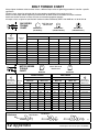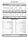
1
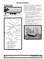
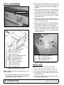
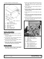
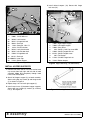
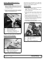
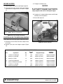
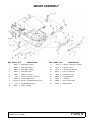
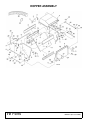
15 cu. ft. Metal Grasscatcher Rev. 8/17/2007 MAN0115 For F-Series Power Units HIS T E ! SAV NUAL MA e it with ine ach lud Inc w'n M tains r Mo . It con ation u o y ual form Man part in other in ir repa t found als. no manu Tested. Proven. Unbeatable. INSTALLATION MANUAL MOW’N MACHINE TO THE DEALER: Assembly and proper installation of this product is the responsibility of the Woods® dealer. Read manual instructions and safety rules. Make sure all items on the Dealer’s Pre-Delivery and Delivery Check Lists in the Operator’s Manual are completed before releasing equipment to the owner. The dealer must complete the Product Registration included with the Operator’s Manual. The customer must sign the registration which certifies that all Dealer Check List items have been completed. The dealer is to return the prepaid postage portion to Woods, give one copy to the customer, and retain one copy. Failure to complete and return this card does not diminish customer’s warranty rights. TO THE OWNER: Read this manual before operating your Woods equipment. The information presented will prepare you to do a better and safer job. Keep this manual handy for ready reference. Require all operators to read this manual carefully and become acquainted with all adjustment and operating procedures before attempting to operate. Replacement manuals can be obtained from your dealer. To locate your nearest dealer, check the Dealer Locator at www.WoodsEquipment.com, or in the United States and Canada call 1-800-319-6637. The equipment you have purchased has been carefully engineered and manufactured to provide dependable and satisfactory use. Like all mechanical products, it will require cleaning and upkeep. Lubricate the unit as specified. Observe all safety information in this manual and safety decals on the equipment. For service, your authorized Woods dealer has trained mechanics, genuine Woods service parts, and the necessary tools and equipment to handle all your needs. Use only genuine Woods service parts. Substitute parts will void the warranty and may not meet standards required for safe and satisfactory operation. Record the model number and serial number of your equipment in the spaces provided: Model: _______________________________ Date of Purchase: _____________________ Serial Number: (see Safety Decal section for location) ____________________________________ Provide this information to your dealer to obtain correct repair parts. Throughout this manual, the term NOTICE is used to indicate that failure to observe can cause damage to equipment. The terms CAUTION, WARNING, and DANGER are used in conjunction with the Safety-Alert Symbol (a triangle with an exclamation mark) to indicate the degree of hazard for items of personal safety. 2 Introduction Gen’l (Rev. 7/20/2007) HOPPER ASSEMBLY ASSEMBLE HOPPER ! Assembly of hopper will be easier if assembled upside down on a flat surface, see Figure 2. Note that Figure 1 shows hopper in the upright position. LEA EL INSTRUCTIVO! Si no lee Ingles, pida ayuda a alguien que si lo lea para que le traduzca las medidas de seguridad. WARNING Only use grass collection system with dual tailwheel option. NOTE: When assembling the hopper, make sure bolts that will interfere with grass clippings are installed with heads on the inside. This will prevent clippings from catching on bolts when the grasscatcher is dumped. Leave hardware loose until hopper is assembled. 1. Lay top section upside down on a flat surface, using Figure 1 as a guide for assembly. NOTE: Do not install bolts in side holes where upper and lower crossmembers will mount (refer to Figure 4, items 12 & 15). 2. Attach side panels (6, 7), upper front panel (8) and back panel (9) to hopper top (1). Make sure side panel corners are outside the front and back panels as shown in Figure 2. 3. Fasten bottom panel (11) to the side panels and to the outside of the front panel (Figure 1). 6 8 9 7 1 1. 4. 70067 5. 70065 6. 1000664 7. 1000665 8. 70528 9. 70530 11. 1000667 70521 Hop- DP1 Figure 2. Assemble Hopper Upside Down per top 1/4 NC x 1/2 Whiz bolt 1/4 NC Whiz nut Right side panel Left side panel Upper front panel Back panel Bottom panel Figure 1. Hopper Assembly MAN0115 (Rev. 3/31/2006) Assembly 3 INSTALL CROSSMEMBERS Front Crossmember 2. Make sure two pivot bearings (13), (Figure 4) are attached to the inside of front cross channel (15) using sheet metal screws (14). Do not tighten at this time. 3. Slide left side door trip lever (17) through opening on left side panel, pivot bearings (13) attached to front cross channel (15), and right side panel. 4. Secure front cross channel (15) to bottom panel using whiz bolts (4) and whiz nuts (5). Tighten sheet metal screws. 5. Attach right dump lever (18) to door trip lever (17), so that both bars face forward. Secure using cap screw (19) and lock nut (20). 6. Mount rear cross channel (12) on outside of bottom panel using whiz bolts (4) and whiz nuts (5) as shown. Make sure pivot hinge is at the bottom. DP7A Figure 3. Side Panel & Front Crossmember Installed 7. Attach left and right door hinge mounts (26, 27) to back and side panels as shown in Figure 5. Use whiz bolt (10) and whiz nut (5) to secure hinge mount to back panel. 5 10 4 5 26 4. 70067 5. 70065 12. 1000679 13. 71163 14. 27610 15. 1000680 17. 1000677 18. 1000678 19. 3184 20. 6128 26. 70536 27. 70537 1/4 NC x 1/2 Whiz bolt 1/4 NC Whiz nut Rear cross channel Pivot bearing 5/16 x 3/4 Sheet metal screw Front cross channel Left side door trip lever Right dump lever 1/4 NC x 1-1/4 HHCS 1/4 NC Lock nut Right door hinge Left door hinge 4. 5. 10. 26. 70067 70065 70068 70536 1/4 NC x 1/2 Whiz bolt 1/4 NC Whiz nut 1/4 NC x 3/4 Whiz bolt Right door hinge Figure 5. Right Door Hinge Mount Installation INSTALL DOOR NOTE: 90° bend on latch bracket faces forward. Figure 4. Crossmember Installation 1. Attach latch brackets (28) to bottom of door (24). NOTE: Hopper should still be upside down. Do not tighten hardware. 2. Place nylon bearings (23) into door hinge mounts. 1. Install front crossmember (16) between right and left side panels. Install crossmember with brackets facing forward as shown in Figure 3. 4 Assembly 3. Insert both left and right door hinges (26, 27) into door hinge mounts. 4. Place door (24) over hinges and secure with whiz bolt (4, 10) and whiz nut (5). (Rev. 8/17/2007) MAN0115 (Rev. 3/31/2006) 5. Torque all hardware according to page 8. 2. Attach latch linkage rod (36) to both right and left door handle mount. Be sure to install spring bracket (35) into clevis when attaching left side (see Figure 7). 3. Attach opposite end of door linkage rod (45) to door handle mount. 4. Adjust linkage so that there is a slight amount of pressure holding the door closed when handle is snapped over center. 5. Attach opposite end of latch linkage rod to door latches. 6. Attach spring (34) to hole in side panel with spring anchor (35) on left side and to spring bracket (33) as shown in Figure 7. 7. Adjust latch linkage rods so that the door latches will release just before the door opens when the door handle is moved forward. 5. 10. 23. 24. 26. 27. 70065 70068 70026 70531 70536 70537 4. 70067 1/4 NC x 1/2 Whiz bolt 1/4 NC Whiz nut 1/4 NC x 3/4 Whiz bolt Nylon bearing Door Right door hinge Left door hinge 48 40 29 31 32 45 39 40 39 40 Figure 6. Door Assembly 36 INSTALL DOOR HANDLE NOTE: Turn hopper assembly over and support in upright position. 1. Attach door handle (29) to left door handle mount as shown in Figure 7. 2. Install stop lever (49) and rubber bumper (50) to right side panel as shown in Figure 8. 3. Install latch pivot bracket (42) to both sides of grasscatcher as shown in Figure 8. 4. Attach door latches (44) to latch pivot brackets. Adjust latch brackets (28) so that the door latches will hold the door tightly shut (see Figure 8). INSTALL LINKAGE 1. Attach door linkage rod (36) to both right and left door hinge as shown in Figure 7 and Figure 8. Place head of clevis pin to the outside. MAN0115 (Rev. 3/31/2006) 33 34 29. 70526 31. 1686 32. 15030 33. 70546 34. 70834 35. 1001501 36. 70547 39. 70024 40. 1326 45. 70548 48. 64151 35 Hopper handle 3/8 NC x 3/4 HHCS 3/8 NC Flange lock nut Link Spring Spring anchor bracket Linkage latch rod Clevis pin, 5/16 x 25/32 Cotter pin, 1/8 x 1/2 Linkage door rod Clevis pin, 3/8 x 1-1/8 Figure 7. Left Side Assembly 5 5. Install rubber bumpers (19). Secure with flange lock nuts (13). 48 40 5 1 9 45 8 49 7 50 19 13 28 2 42 44 4. 70067 5. 70065 28. 70538 36. 70547 39. 70024 40. 1326 41. 4378 42. 70543 44. 70545 45. 70548 48. 64151 49. 1000670 50. 71444 4 36 5 39 40 41 40 1/4 NC x 1/2 Whiz bolt 1/4 NC Whiz nut Latch bracket Linkage latch rod Clevis pin Cotter pin, 1/8 x 1/2 5/16 Flat washer Latch pivot bracket Left side door latch Linkage door rod Clevis pin Lever stop Rubber bumper Figure 8. Right Side 6 1. 2. 5. 6. 7. 8. 9. 13. 19. 74082 74083 74084 920 15030 62153 565 14139 71444 7 Right hopper support Left hopper support Cross brace 3/8 NC x 1-3/4 Cap screw GR5 3/8 NC Flanged lock nut 3/8 NC Flanged screw Flat Washer 5/16 NC Flange lock nut Rubber bumper Figure 9. Hopper Mounting (Left Side Shown) INSTALL HOPPER SUPPORTS 1. Remove two center 3/8 NC x 3/4 hex washer head cap screws from both right and left side of hood assembly. Note: Drill completely through hood frame if not already done. 2. Attach left hopper support (2) to hood assembly. Secure using two cap screws (6) and flange screw (7) as shown in Figure 9. 3. Repeat steps 1 & 2 to install right support (1). 4. Install cross brace (5) between hopper supports. Secure with cap screws (8), washer (9), and lock nut (7). See Figure 10. 6 Assembly Figure 10. Mounting Bracket Instructions (Rev. 8/17/2007) MAN0115 (Rev. 3/31/2006) INSTALL REAR HOPPER SUPPORT & REAR HOPPER PIVOT Align hinges of rear crossmember (12) on hopper with hinges of rear hopper pivot (4). Insert clevis pins (14) and hair pins (15) as shown in Figure 12. 1. Attach rear hopper support (3) to the rear of the power unit using four flanged head cap screws (8), standard flat washers (9), and two flange lock nuts (7) as shown in Figure 11. 2. Attach the rear hopper pivot (4) to the rear hopper support using four flanged head cap screws (8), washers (9), and flange lock nuts (7). 8 9 1. Attach cable (10) to rear of power unit on both right and left sides as shown in Figure 13. NOTE: Remove cap screw for ground cable on 21D & 25L power units. 2. Secure with flanged cap screw (8), washer (9), and flange lock nut (7). Leave hardware loose at this time. 3. Remove the fourth whiz bolt and whiz nut from the bottom of both right and left side panels. 7 4. Install whiz bolt (16), other end of cable (10), flat washer (9), and whiz nut previously removed in this hole position as shown in Figure 13. 4 7 ATTACH CABLE 5. Pivot hopper back and allow weight of hopper on cables. Torque hardware at this time. 8 3 16 9 8 3. 4. 7. 8. 9. 74082 73678 15030 62153 565 7 9 DP4 10 Rear hopper support Rear hopper pivot 3/8 NC Flange lock nut 3/8 NC x 1 Flanged cap screw 3/8 Standard flat washer Figure 11. Rear Hopper Support & Rear Hopper Pivot 9 7. 8. 9. 10. 16. MOUNT HOPPER ASSEMBLY 12 15030 62153 565 73957 70068 8 7 3/8 NC Flange lock nut (2) 3/8 NC Flanged cap screw (2) 3/8 Flat washer (4) Cable 1/4 NC x 3/4 Whiz bolt (2) DP3 Figure 13. Cable Installed (Right Side Shown) 4 14 15 4. 73678 12. 1000679 14. 63523 15. 2688 Rear hopper pivot Rear cross channel (Hopper) 3/4 x 4-1/2 Clevis pin (2) 5/32 Hair pin cotter (2) DP2 Figure 12. Hinge Pin Installed (Left Hinge Shown) (Rev. 8/17/2007) MAN0115 (Rev. 3/31/2006) Assembly 7 SECURE HOPPER 3. Tilt hopper assembly back. NOTICE 1. Rotate hopper onto right and left hopper supports. 2. Insert 3/8 lynch pins (18) to attach front hopper crossmember to support brace as shown in Figure 14. ■ Do not attempt to tilt hopper to service position unless hopper is completely empty. Failure to empty hopper could result in damage to hopper. 4. On power unit, unhook rubber latches and lift hood assembly to service position. 5. Secure with prop rod. 18 18. 33000 3/8 x 2-1/4 Lynch pins Figure 14. Latch Locked into Position POSITION HOOD FOR SERVICING ENGINE To flip hood up for servicing engine, follow these steps: DP5 1. Disconnect vacuum hose from hose adapter chute on vacuum. Figure 15. Servicing Engine 2. Remove lynch pins from hopper support (Figure 14). TORQUE SPECIFICATIONS Cap Screw Qty Wrench Size 4 1/4 NC x 1/2 Whiz bolt 68 7/16 10 lbs-ft (13 N-m) Hopper Assembly 6 3/8 NC x 1-3/4 HHCS 4 9/16 35 lbs-ft (47 N-m) Mount Assembly 8 3/8 NC x 1 FHCS 12 9/16 35 lbs-ft (47 N-m) Mount Assembly 10 1/4 NC x 3/4 Whiz bolt 14 7/16 10 lbs-ft (13 N-m) Hopper Assembly 14 5/16 x 3/4 Sheet metal screw 4 1/2 19 lbs-ft (26 N-m) Hopper Assembly 19 1/4 NC x 1-1/4 HHCS 1 7/16 10 lbs-ft (13 N-m) Hopper Assembly 31 3/8 NC x 3/4 HHCS 2 9/16 35 lbs-ft (47 N-m) Hopper Assembly Ref 8 Assembly Required Torque Hardware Location MAN0115 (Rev. 3/31/2006) MOUNT ASSEMBLY REF PARTS QTY DESCRIPTION REF PARTS QTY DESCRIPTION 1 74082 1 Right hopper support 11 4528 4 5/16 NC x 1-3/4 Cap screw GR5 2 74083 1 Left hopper support 12 6778 4 5/16 NC Lock nut 3 73677 1 Rear hopper support 13 14139 2 5/16 NC Flange lock nut 4 73678 1 Rear hopper pivot 14 63523 2 3/4 x 4-1/2 Clevis pin 5 74084 1 Hopper cross brace 15 2688 2 5/32 Hair pin cotter 6 920 4 3/8 NC x 1-3/4 Cap screw GR5 16 70068 2 1/4 x 3/4 Whiz bolt 70065 2 1/4 Whiz nut 7 15030 12 3/8 NC Flange lock nut 17 8 62153 12 3/8 NC x 1 Flanged head cap screw 18 33000 2 3/8 x 2-1/4 Lynch pin 19 71444 2 Rubber bumper 9 565 8 3/8 Standard flat washer 10 73957 2 Cable assembly MAN0115 (Rev.3/31/2006) Parts 9 HOPPER ASSEMBLY 10 Parts MAN0115 (Rev. 3/31/2006) HOPPER ASSEMBLY PART LIST REF PARTS QTY DESCRIPTION REF PARTS QTY DESCRIPTION 1 70521 1 Hopper top 28 70538 2 Latch bracket 2 70504 1 Window 29 70526 1 Hopper handle 3 70505 2 Mounting bracket 30 70527 1 Handle grip, .812 x 4 4 70067 68 1/4 NC x 1/2 Whiz bolt 31 1686 2 3/8 NC x 3/4 HHCS 5 70065 82 1/4 NC Whiz nut 32 15030 2 3/8 NC Flange lock nut 6 1000664 1 Right side panel 33 70546 1 Link, .19 x .75 x 4.0 7 1000665 1 Left side panel 34 70834 1 Spring 8 70528 1 Upper front panel 35 1001501 1 Spring anchor bracket 9 70530 1 Back panel 36 70547 2 Linkage latch rod 10 70068 14 1/4 NC x 3/4 Whiz bolt 37 5283 2 5/16 NF Hex nut 11 1000667 1 Bottom panel 38 70022 2 Adjustable clevis, 5/16 NF 12 1000679 1 Rear cross channel 39 70024 2 Clevis pin, 5/16 x 25/32 13 71163 2 Pivot bearing 40 1326 8 Cotter pin, 1/8 x 1/2 14 27610 4 5/16 x 3/4 Sheet metal screw 41 4378 9 5/16 Flat washer 15 1000680 1 Front cross channel 42 70543 1 Latch pivot bracket 16 74085 1 Front crossmember 43 70544 1 Right side door latch 17 1000677 1 Left door trip lever 44 70545 1 Left side door latch 18 1000678 1 Right dump lever 45 70548 2 Linkage door rod 19 3184 1 1/4 NC x 1-1/4 HHCS 46 1271 2 3/8 NF Hex nut 20 6128 1 1/4 NC Lock nut 47 70360 2 Adjustable clevis, 3/8NF 21 70534 1 Right door hinge mount 48 64151 2 Clevis pin, 3/8 x 1-1/8 22 70535 1 Left door hinge mount 49 1000670 1 Lever stop 23 70026 2 Nylon bearing (included. w/ 21 & 22) 50 71444 1 Rubber bumper 24 70531 1 Door 51 14139 1 5/16 NC Flange lock nut 25 70552 1 Door seal 52 1001018 1 64" Flex hose 26 70536 2 Right door hinge 53 70523 1 6" Hose clamp 27 70537 2 Left door hinge MAN0115 (Rev.3/31/2006) Parts 11 BOLT TORQUE CHART Always tighten hardware to these values unless a different torque value or tightening procedure is listed for a specific application. Fasteners must always be replaced with the same grade as specified in the manual parts list. Always use the proper tool for tightening hardware: SAE for SAE hardware and Metric for metric hardware. Make sure fastener threads are clean and you start thread engagement properly. All torque values are given to specifications used on hardware defined by SAE J1701 MAR 99 & J1701M JUL 96. SAE Bolt Head Identification SAE SERIES TORQUE CHART A SAE Grade 2 (No Dashes) SAE Grade 8 (6 Radial Dashes) SAE Grade 5 (3 Radial Dashes) MARKING ON HEAD A Diameter (Inches) Wrench Size SAE 2 lbs-ft SAE 5 N-m SAE 8 lbs-ft N-m lbs-ft N-m 1/4" 7/16" 6 8 10 13 14 18 5/16" 3/8" 1/2" 9/16" 12 23 17 31 19 35 26 47 27 49 37 67 7/16" 1/2" 5/8" 3/4" 36 55 48 75 55 85 75 115 78 120 106 163 9/16" 5/8" 13/16" 15/16" 78 110 106 149 121 170 164 230 171 240 232 325 3/4" 7/8" 1-1/8" 1-5/16" 192 306 261 416 297 474 403 642 420 669 569 907 1" 1-1/2" 467 634 722 979 1020 1383 METRIC SERIES TORQUE CHART A A Metric Bolt Head Identification 8.8 Metric Grade 8.8 10.9 Metric Grade 10.9 COARSE THREAD FINE THREAD MARKING ON HEAD MARKING ON HEAD A Diameter & Thread Pitch (Millimeters) Wrench Size N-m lbs-ft N-m lbs-ft N-m lbs-ft N-m lbs-ft Diameter & Thread Pitch (Millimeters) 6 x 1.0 8 x 1.25 10 mm 13 mm 8 20 6 15 11 27 8 20 8 21 6 16 11 29 8 22 6 x 1.0 8 x 1.0 10 x 1.5 12 x 1.75 16 mm 18 mm 39 68 29 50 54 94 40 70 41 75 30 55 57 103 42 76 10 x 1.25 12 x 1.25 14 x 2.0 16 x 2.0 21 mm 24 mm 109 169 80 125 151 234 111 173 118 181 87 133 163 250 120 184 14 x 1.5 16 x 1.5 18 x 2.5 20 x 2.5 27 mm 30 mm 234 330 172 244 323 457 239 337 263 367 194 270 363 507 268 374 18 x 1.5 20 x 1.5 22 x 2.5 24 x 3.0 34 mm 36 mm 451 571 332 421 623 790 460 583 495 623 365 459 684 861 505 635 22 x 1.5 24 x 2.0 30 x 3.0 46 mm 1175 867 1626 1199 1258 928 1740 1283 30 x 2.0 Typical Washer Installations Bolt Metric 8.8 Lock Washer Metric 10.9 Metric 8.8 Metric 10.9 Flat Washer 8/9/00 12 Appendix Bolt Torque & Size Charts (Rev. 10/10/2005) BOLT SIZE CHART NOTE: Chart shows bolt thread sizes and corresponding head (wrench) sizes for standard SAE and metric bolts. SAE Bolt Thread Sizes 5/16 3/8 1/2 IN MM 5/8 3/4 7/8 1 2 3 4 5 6 7 25 50 75 100 125 150 175 Metric Bolt Thread Sizes 8MM 10MM 12MM 14MM 16MM 18MM ABBREVIATIONS AG ............................................................. Agriculture ATF...............................Automatic Transmission Fluid BSPP .......................... British Standard Pipe Parallel BSPTM...............British Standard Pipe Tapered Male CV .................................................. Constant Velocity CCW ............................................ Counter-Clockwise CW ............................................................. Clockwise F..................................................................... Female GA ................................................................... Gauge GR (5, etc.) ......................................... Grade (5, etc.) HHCS .......................................Hex Head Cap Screw HT ......................................................... Heat-Treated JIC............... Joint Industry Council 37° Degree Flare LH ...............................................................Left Hand LT ......................................................................... Left m ....................................................................... Meter mm ..............................................................Millimeter M ........................................................................ Male MPa........................................................Mega Pascal N .................................................................... Newton Bolt Torque & Size Charts (Rev. 10/10/2005) NC ....................................................National Coarse NF......................................................... National Fine NPSM ...................National Pipe Straight Mechanical NPT ........................................ National Pipe Tapered NPT SWF ....... National Pipe Tapered Swivel Female ORBM ......................................... O-Ring Boss - Male P .........................................................................Pitch PBY .................................................... Power-Beyond psi ........................................ Pounds per Square Inch PTO ................................................... Power Take Off QD ..................................................Quick Disconnect RH ............................................................Right Hand ROPS.......................... Roll-Over Protective Structure RPM.......................................Revolutions Per Minute RT ...................................................................... Right SAE ........................Society of Automotive Engineers UNC ....................................................Unified Coarse UNF ........................................................ Unified Fine UNS ....................................................Unified Special Appendix 13 LIMITED WARRANTY (Mow’n Machine Zero-Turn Mower and Woods Boundary Utility Vehicle Replacement Parts) TM TM Woods Equipment Company (“WOODS”) warrants replacement parts for Mow’n Machine zero-turn mowers and attachments and Woods Boundary utility vehicles, accessories and attachments to be free from defect in material and workmanship for a period of ninety (90) days from the date of delivery of the product to the original purchaser. TM TM IMPLIED WARRANTIES OF MERCHANTABILITY AND/OR FITNESS FOR A PARTICULAR PURPOSE ARE LIMITED IN DURATION TO A PERIOD OF NINETY (90) DAYS FROM THE DATE OF DELIVERY OF THE PRODUCT TO THE ORIGINAL PURCHASER. Some states do not allow limitations on how long an implied warranty lasts, so the above limitation may not apply to you. This Warranty is extended solely to the original purchaser of the product. Should the original purchaser sell or otherwise transfer the product to a third party, this Warranty does not transfer to the third party purchaser in any way. There are no third party beneficiaries of this Warranty. This Warranty does not cover normal wear or tear, or normal maintenance items, or any damage, failure or loss caused by improper operation, improper maintenance, misuse, or an accident. WOODS’ obligation under this Warranty is limited to, at WOODS’ option, the repair or replacement, free of charge, of the product if the product is defective or in noncompliance with this Warranty. The product must be returned to WOODS with proof of purchase within thirty (30) days after such defect or noncompliance is discovered or should have been discovered, routed through the dealer and distributor from whom the purchase was made, transportation charges prepaid. WOODS shall complete such repair or replacement within a reasonable time after WOODS receives the product. WOODS shall not be liable for any incidental or consequential losses, damages or expenses, arising directly or indirectly from the product, whether such claim is based upon breach of contract, breach of warranty, negligence, strict liability in tort or any other legal theory. Without limiting the foregoing, WOODS shall not be liable for any damages relating to (i) lost profits, business, revenues or goodwill; (ii) any expense or loss incurred for labor, supplies, substitute machinery or rental; or (iii) any other type of damage to property or economic loss. Some states do not allow the exclusion or limitation of incidental or consequential damages, so the above limitations may not apply to you. No agent, representative, dealer, distributor, service person, salesperson, or employee of any company, including without limitation, WOODS, its authorized dealers, distributors, and service centers, is authorized to alter, modify, or enlarge this Warranty. This Warranty gives you specific legal rights, and you may also have other rights which may vary from state to state. Answers to any questions regarding warranty service and locations may be obtained by contacting: Woods Equipment Company 2606 South Illinois Route 2 Post Office Box 1000 Oregon, Illinois 61061 800-319-6637 tel 800-399-6637 fax www.WoodsEquipment.com F-8495 MM & Boundary Repair Parts (Rev. 2/15/2006) LIMITED WARRANTY (Mow’n Machine Zero-Turn Mowers and Woods Boundary Utility Vehicles) TM TM Please Enter Information Below and Save For Future Reference. Date Purchased: __________________________ From (Dealer): _____________________________________ Model Number: __________________________ Serial Number: _____________________________________ WHAT IS COVERED: Woods Equipment Company (“WOODS”) warrants Mow’n MachineTM zero-turn mowers and attachments and Woods BoundaryTM utility vehicles, accessories and attachments to be free from defect in material and workmanship for the warranty periods listed below. FOR HOW LONG: Mow’n Machine Model #CZ2136B, CZ1736K, CZ1942K, CZ1948K, CZ1952K, FE21B, FZ23B, FZ25D, FZ28K, ME2052B, MZ1952K, MZ2652G, MZ2561K, MZ2761, MZ3361G, MZ3372G, MZ2061YD & attachments are warranted for two (2) years from the date of delivery to the original purchaser or 2000 hours of operation, whichever occurs first. Mow’n Machine ME and MZ Series Models, serial number XXXXXXXX300 and above, Limited Lifetime Warranty on deck, deck cradle, and engine deck for the life of the machine to the original retail purchaser. Woods Boundary utility vehicle Model #MAV350, MAV480, MAV4x4, accessories & attachments are warranted for two (2) years from the date of delivery to the original purchaser. IMPLIED WARRANTIES OF MERCHANTABILITY AND/OR FITNESS FOR A PARTICULAR PURPOSE ARE LIMITED IN DURATION TO THE DURATION OF THE WRITTEN WARRANTY PERIODS LISTED ABOVE. Some states do not allow limitations on how long an implied warranty lasts, so the above limitation may not apply to you. WHO IS COVERED: This Warranty is extended solely to the original purchaser of the product. Should the original purchaser sell or otherwise transfer the product to a third party, this Warranty does not transfer to the third party purchaser in any way. There are no third party beneficiaries of this Warranty. WHAT IS NOT COVERED: This Warranty does not cover normal wear or tear, or normal maintenance items, or any damage, failure or loss caused by: 1. Improper operation, improper maintenance, misuse, or an accident; 2. Any modification or repair by someone other than WOODS, a WOODS authorized dealer or distributor, and/or a WOODS authorized service center; or 3. Repairs made with parts other than those obtainable through WOODS. WOODS makes no warranty, express or implied, with respect to engines, batteries, tires or other parts or accessories not manufactured by WOODS. Warranties for these items, if any, are provided separately by their respective manufacturers. WHAT WOODS WILL DO TO CORRECT PROBLEMS: WOODS’ obligation under this Warranty is limited to, at WOODS’ option, the repair or replacement, free of charge, of the product if the product is defective or in noncompliance with this Warranty. The product must be returned to WOODS with proof of purchase within thirty (30) days after such defect or noncompliance is discovered or should have been discovered, routed through the dealer and distributor from whom the purchase was made, transportation charges prepaid. WOODS shall complete such repair or replacement within a reasonable time after WOODS receives the product. OTHER LIMITATIONS: WOODS shall not be liable for any incidental or consequential losses, damages or expenses, arising directly or indirectly from the product, whether such claim is based upon breach of contract, breach of warranty, negligence, strict liability in tort or any other legal theory. Without limiting the foregoing, WOODS shall not be liable for any damages relating to (i) lost profits, business, revenues or goodwill; (ii) any expense or loss incurred for labor, supplies, substitute machinery or rental; or (iii) any other type of damage to property or economic loss. Some states do not allow the exclusion or limitation of incidental or consequential damages, so the above limitations may not apply to you. No agent, representative, dealer, distributor, service person, salesperson, or employee of any company, including without limitation, WOODS, its authorized dealers, distributors, and service centers, is authorized to alter, modify, or enlarge this Warranty. HOW STATE LAW APPLIES: This Warranty gives you specific legal rights, and you may also have other rights which may vary from state to state. QUESTIONS: Answers to any questions regarding warranty service and locations may be obtained by contacting: Woods Equipment Company 2606 South Illinois Route 2 Post Office Box 1000 Oregon, Illinois 61061 800-319-6637 tel 800-399-6637 fax www.WoodsEquipment.com F-8045 MM & Boundary (Rev. 7/6/2007) PART NO. MAN0115 Woods Equipment Company 2606 South Illinois Route 2 Post Office Box 1000 Oregon, Illinois 61061 800-319-6637 tel 800-399-6637 fax www.WoodsEquipment.com © 2001 Woods Equipment Company. All rights reserved. WOODS, the Woods logo, and "Tested. Proven. Unbeatable." are trademarks of Woods Equipment Company. All other trademarks, trade names, or service marks not owned by Woods Equipment Company that appear in this manual are the property of their respective companies or mark holders. Specifications subject to change without notice.