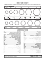
1
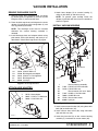
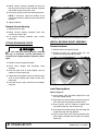
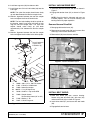
(Rev. 12/14/2007) MAN0258 For Mower Models MX54, MX61 on F-Series Power Units Tested. Proven. Unbeatable. OPERATOR'S MANUAL MOW’N MACHINE VACUUM TM TO THE DEALER: Assembly and proper installation of this product is the responsibility of the Woods® dealer. Read manual instructions and safety rules. Make sure all items on the Dealer’s Pre-Delivery and Delivery Check Lists in the Operator’s Manual are completed before releasing equipment to the owner. The dealer must complete the Product Registration included with the Operator’s Manual. The customer must sign the registration which certifies that all Dealer Check List items have been completed. The dealer is to return the prepaid postage portion to Woods, give one copy to the customer, and retain one copy. Failure to complete and return this card does not diminish customer’s warranty rights. TO THE OWNER: Read this manual before operating your Woods equipment. The information presented will prepare you to do a better and safer job. Keep this manual handy for ready reference. Require all operators to read this manual carefully and become acquainted with all adjustment and operating procedures before attempting to operate. Replacement manuals can be obtained from your dealer. To locate your nearest dealer, check the Dealer Locator at www.WoodsEquipment.com, or in the United States and Canada call 1-800-319-6637. The equipment you have purchased has been carefully engineered and manufactured to provide dependable and satisfactory use. Like all mechanical products, it will require cleaning and upkeep. Lubricate the unit as specified. Observe all safety information in this manual and safety decals on the equipment. For service, your authorized Woods dealer has trained mechanics, genuine Woods service parts, and the necessary tools and equipment to handle all your needs. Use only genuine Woods service parts. Substitute parts will void the warranty and may not meet standards required for safe and satisfactory operation. Record the model number and serial number of your equipment in the spaces provided: Model: _______________________________ Date of Purchase: _____________________ Serial Number: (see Safety Decal section for location) ____________________________________ Provide this information to your dealer to obtain correct repair parts. Throughout this manual, the term NOTICE is used to indicate that failure to observe can cause damage to equipment. The terms CAUTION, WARNING, and DANGER are used in conjunction with the Safety-Alert Symbol (a triangle with an exclamation mark) to indicate the degree of hazard for items of personal safety. 2 Introduction Gen’l (Rev. 7/20/2007) TABLE OF CONTENTS INTRODUCTION . . . . . . . . . . . . . . . . . . . . . . . . . . . . . . . . . . . . . . . . . . . . . . 2 GENERAL INFORMATION . . . . . . . . . . . . . . . . . . . . . . . . . . . . . . . . . . . . . . 3 SAFETY RULES . . . . . . . . . . . . . . . . . . . . . . . . . . . . . . . . . . . . . . . . . . . . . . 4 SAFETY DECALS . . . . . . . . . . . . . . . . . . . . . . . . . . . . . . . . . . . . . . . . . . . . . 6 INSTALLATION . . . . . . . . . . . . . . . . . . . . . . . . . . . . . . . . . . . . . . . . . . . . . . . 7 DEALER CHECK LISTS . . . . . . . . . . . . . . . . . . . . . . . . . . . . . . . . . . . . . . . 10 SERVICE . . . . . . . . . . . . . . . . . . . . . . . . . . . . . . . . . . . . . . . . . . . . . . . . . . . .11 PARTS LISTS . . . . . . . . . . . . . . . . . . . . . . . . . . . . . . . . . . . . . . . . . . . . . . . 12 BOLT TORQUE CHART . . . . . . . . . . . . . . . . . . . . . . . . . . . . . . . . . . . . . . . 14 BOLT SIZE CHART & ABBREVIATIONS . . . . . . . . . . . . . . . . . . . . . . . . . . 15 REPLACEMENT PARTS WARRANTY . . . . . . . . . . . . . . . . . . . . . . . . . . . . 16 PRODUCT WARRANTY . . . . . . . . . . . . . . . . . . . . . . . INSIDE BACK COVER GENERAL INFORMATION The purpose of this manual is to assist you in operating and maintaining your vacuum system. Read it carefully. It furnishes information and instructions that will help you achieve years of dependable performance. These instructions have been compiled from extensive field experience and engineering data. Some information may be general in nature due to unknown and varying operating conditions. However, through experience and these instructions, you should be able to develop procedures suitable to your particular situation. The illustrations and data used in this manual were current at the time of printing but, due to possible inline production changes, your machine may vary slightly in MAN0258 (Rev. 12/14/2007) detail. We reserve the right to redesign and change the machines as may be necessary without notification. WARNING ■ Some illustrations in this manual show the mower with safety shields removed to provide a better view. The mower should never be operated with any safety shielding removed. Throughout this manual, references are made to right and left directions. These are determined by standing behind the equipment facing the direction of forward travel. Introduction 3 SAFETY RULES ATTENTION! BECOME ALERT! YOUR SAFETY IS INVOLVED! Safety is a primary concern in the design and manufacture of our products. Unfortunately, our efforts to provide safe equipment can be wiped out by an operator’s single careless act. In addition to the design and configuration of equipment, hazard control and accident prevention are dependent upon the awareness, concern, judgement, and proper training of personnel involved in the operation, transport, maintenance, and storage of equipment. It has been said, “The best safety device is an informed, careful operator.” We ask you to be that kind of operator. ! LEA EL INSTRUCTIVO! Si no lee Ingles, pida ayuda a alguien que si lo lea para que le traduzca las medidas de seguridad. TRAINING Safety instructions are important! Read all attachment and power unit manuals; follow all safety rules and safety decal information. (Replacement manuals and safety decals are available from your dealer. To locate your nearest dealer, check the Dealer Locator at www.WoodsEquipment.com, or in the United States and Canada call 1-800-3196637.) Failure to follow instructions or safety rules can result in serious injury or death. PREPARATION Check that all hardware is properly installed. Always tighten to torque chart specifications unless instructed otherwise in this manual. Always wear relatively tight and belted clothing to avoid entanglement in moving parts. Wear sturdy, rough-soled work shoes and protective equipment for eyes, hair, hands, hearing, and head. Make sure attachment is properly secured, adjusted, and in good operating condition. Remove accumulated debris from this equipment, power unit, and engine to avoid fire hazard. Make sure all safety decals are installed. Replace if damaged. (See Safety Decals section for location.) Make sure shields and guards are properly installed and in good condition. Replace if damaged. Be sure either the discharge chute, mulching end cap, or complete vacuum attachment is installed and in good condition. Replace if damaged. Inspect and clear area of stones, branches, or other hard objects that might be thrown, causing injury or damage. OPERATION Keep bystanders away from equipment. If you do not understand any part of this manual and need assistance, see your dealer. Do not operate or transport equipment while under the influence of alcohol or drugs. Know your controls and how to stop engine and attachment quickly in an emergency. Operate only in daylight or good artificial light. Operators must be instructed in and be capable of the safe operation of the equipment, its attachments, and all controls. Do not allow anyone to operate this equipment without proper instructions. Never allow children or untrained persons to operate equipment. Data indicates that those operators age 60 years and above are involved in a large percentage of riding mower-related injuries. Those operators should evaluate their ability to operate the riding mower safely enough to protect themselves and others from injury. 4 Safety Keep hands, feet, hair, and clothing away from equipment while engine is running. Stay clear of all moving parts. Never allow riders on power unit or attachment. Watch for hidden hazards on the terrain during operation. Before making any adjustments on attachment, stop engine and engage parking brake. Never adjust or work on attachment while the power unit or attachment is running. Do not allow bystanders in the area when operating, attaching, removing, assembling, or servicing equipment. Mow’n Machine Vacuum (10/8/2004) SAFETY RULES ATTENTION! BECOME ALERT! YOUR SAFETY IS INVOLVED! Keep children out of the mowing area and under the watchful care of a responsible adult other than the operator. Be alert and turn machine off if a child enters the mowing area. Before attempting to unplug vacuum hoses, disengage PTO, stop power unit, and remove key. Before performing any service or maintenance, lower attachment to ground, turn off power unit engine, remove key, and disconnect battery ground cable (negative -). Be sure either the discharge chute, mulching end cap, or complete vacuum attachment is installed and in good condition. Replace if damaged. TRANSPORTATION Use extra care when loading or unloading the machine onto a trailer or truck. Never allow riders on power unit or attachment. Do not operate or transport on steep slopes. Do not operate or transport equipment while under the influence of alcohol or drugs. engine, remove key, and disconnect battery ground cable (negative -). Do not modify or alter or permit anyone else to modify or alter the equipment or any of its components in any way. Always wear relatively tight and belted clothing to avoid entanglement in moving parts. Wear sturdy, rough-soled work shoes and protective equipment for eyes, hair, hands, hearing, and head. Make sure attachment is properly secured, adjusted, and in good operating condition. Keep all persons away from operator control area while performing adjustments, service, or maintenance. Tighten all bolts, nuts and screws to torque chart specifications. Check that all cotter pins are installed securely to ensure equipment is in a safe condition before putting unit into service. Make sure all safety decals are installed. Replace if damaged. (See Safety Decals section for location.) MAINTENANCE Make sure shields and guards are properly installed and in good condition. Replace if damaged. Before attempting to unplug vacuum hoses, disengage PTO, stop power unit, and remove key. STORAGE Before performing any service or maintenance, lower attachment to ground, turn off power unit Keep children and bystanders away from storage area. Mow’n Machine Vacuum (10/8/2004) Safety 5 SAFETY & INSTRUCTIONAL DECALS ATTENTION! BECOME ALERT! YOUR SAFETY IS INVOLVED! Replace Immediately If Damaged! BE CAREFUL! Use a clean, damp cloth to clean safety decals. MODEL NO. Replacement safety decals can be ordered free from your Woods dealer. To locate your nearest dealer, check the Dealer Locator at www.WoodsEquipment.com, or in the United States and Canada call 1-800-319-6637. WARNING THROWN OBJECT HAZARD CAN RESULT IN SERIOUS INJURY OR DEATH. NEVER OPERATE WITHOUT DISCHARGE CHUTE OR ENTIRE GRASSCATCHER SYSTEM IN PLACE. 72672 SERIAL NO. Woods Equipment Company Oregon, Illinois, U.S.A. 2 - SERIAL NUMBER PLATE (Located on back side of blower housing) DANGER SHIELD MISSING DO NOT OPERATE - PUT SHIELD ON 18869 Avoid spraying too close to decals when using a pressure washer; high-pressure water can enter through very small scratches or under edges of decals causing them to peel or come off. 3 - PN 18869 1 - PN 72672 3 CD6274 2 1 6 Safety MAN0258 (Rev. 12/14/2007) VACUUM INSTALLATION REMOVE DISCHARGE CHUTE 1. Remove mower deck discharge chute and hinge by removing two carriage bolts (2) and nuts (3) and lifting the chute (1) away from the deck. 2. Place the discharge chute and hinge on the chute adapter (4) and secure with carriage bolts (2) and nuts (3) previously removed. 1. Attach hose adapter (2) to vacuum housing (1) using six whiz bolts (3) and whiz nuts (4). NOTE: To prevent grass buildup inside the adapter, install bolts with nuts (4) on the outside as shown in Figure 2. INSTALL VACUUM HOUSING NOTE: The discharge chute must be installed whenever the vacuum housing assembly is removed. 1 3. Install discharge chute and adapter to deck using pivot mount, clevis shaft bracket, and lynch pin as described in ‘Attach Discharge Chute” on page 8. A 34 34 34 61 62 37 61 59 38 60 60 CD6275-1 34. 59. 60. 61. 62. 73163 75208 78182 78107 33000 5/16 NC Whiz nut Discharge chute adapter 5/16 NC x 1 Carriage bolt Discharge chute Lynch pin Figure 1. Discharge Removal ATTACH HOSE ADAPTER 1. 2. 3. 4. Vacuum fan housing 70570 Hose adapter 70067 1/4 NC x 1/2 Whiz bolt 70065 1/4 NC Whiz nut 3 2 33 62 CD6276-1 35 37 36 1. 33. 34. 35. 36. 37. 38. 62. 71851 73163 71637 70069 75109 33000 Vacuum housing assembly 5/16 NC x 3/4 Hex whiz bolt 5/16 NC Whiz nut Vacuum mount (54" or 61" deck) 3/8 NC x 1 Hex whiz bolt 3/8 NC Whiz nut Vacuum front mount Lynch pin Figure 3. Vacuum Housing Installation 1. Install vacuum mount bracket (35) using three whiz bolts (36) and whiz nuts (37). 4 1 CD6281-1 Figure 2. Hose Adapter Installation MAN0258 (Rev. 12/14/2007) 2. Install vacuum front mount (38) using whiz bolts (33) and whiz nuts (34). 3. Insert the pivot shaft (A) on the vacuum housing assembly (1) into sleeve of vacuum mount (35). Installation 7 4. Rotate vacuum housing assembly into place so that the clevis shaft on vacuum housing assembly slips inside vacuum front mount (38). 5. Install lynch pin (62) to lock the housing into place. NOTE: If necessary, adjust the position of the vacuum front mount to allow for easy installation of lynch pin. 62 6. Tighten hardware. Remove Vacuum Housing 1. Remove lynch pin (62). 2. Rotate vacuum housing assembly away from vacuum front mount (38). 3. Lift vacuum housing assembly from vacuum mount (35). DP1 Figure 4. Discharge Chute with Adapter Installed INSTALL BEARING MOUNT ASSEMBLY ATTACH DISCHARGE CHUTE WARNING Remove Hardware 1. Remove center and right belt shield. Be sure either the discharge chute, mulching end cap, or complete vacuum attachment is installed and in good condition. Replace if damaged. 2. Remove top bolt (A), cupped washer (B), and spacer from the right spindle assembly. A 1. Remove vacuum housing from deck. 2. Install chute attached. adapter with discharge B chute 3. Insert the pivot shaft of chute adapter (59) into sleeve of vacuum mount (35). 4. Rotate the chute adapter in place so that the clevis shaft on chute adapter slips inside vacuum front mount (38). 5. Install the lynch pin (62), to lock the chute adapter into place. DP2 Figure 5. Right Spindle and Sheave Assembly Install Bearing Mount Refer to Figure 6. 1. Install washer (49) and lower coupler drive (39) over right spindle sheave. 2. Align keyway of sheave and flex coupler and install .25 x .069" square key (40) that comes with kit. 3. Secure sheave and flex coupler to spindle shaft using sheave bolt (41) and flat washer (9). 4. Place nylon flex coupler sleeve (42) over lower flex coupler drive (39) and align grooves. 5. Install vacuum drive mount (43) by positioning the drive spindle assembly into the nylon flex coupler sleeve (42). 8 Installation MAN0258 (Rev. 12/14/2007) INSTALL VACUUM DRIVE BELT 6. Install two cage nuts (63) into slots on deck. 7. Install three new 5/16 x 3/4 whiz bolts (33) into the 5/16 cage. 1. Install belt (56) over sheaves and idler as shown in Figure 7. NOTE: The nylon flex coupler should move freely up and down between the two flex coupler hubs. 2. Engage belt tension lever (25) as shown in Figure 8. 8. Maintain alignment between the two flex coupler hubs and tighten the three 5/16 whiz bolts. NOTE: Check that belt is alignment and parts are installed properly. Test run vacuum housing and bearing mount for proper operation. NOTE: The four bolts holding the drive spindle on the bearing mount have been left loose to help align the two flex coupler hubs. The nylon flex coupler should move freely up and down approximately 1/16" between the two flex coupler hubs. 9. Maintain alignment between the two flex coupler hubs and tighten the four bolts to the drive spindle. Remove Vacuum Drive Belt 1. Disengage belt tension lever (25). 2. Remove two 3-prong knobs (58) and vacuum drive shield (57) from vacuum drive mount. 3. Remove belt (56) from sheaves and idler. 56 33 Loose Hardware Tighten After Installation (4) 33 33 43 42 40 41 Figure 7. Vacuum Drive Belt Layout 9 39 63 63 49 25 CD6277-1 9. 70036 .406 x 1.27 x .120 Flat washer 33. 71851 5/16 NC x 3/4 Whiz bolt 39. 72656 Lower flex coupler 40. 480752 1/4 x 1/4 Square key 41. 78188 3/8 NF x 1 Cap screw GR5 42. 72658 Coupler sleeve 43. Vacuum drive mount (61" or 54") 49. 71495 Washer, 1" ID 63. 74047 5/16 NC Cage nut Figure 6. Vacuum Drive Mount Installation Figure 8. Belt Tension lever Engaged INSTALL BELT SHIELD 1. Place belt shield (31) over vacuum housing. Secure using two whiz bolts (33), whiz nuts (34), and one whiz bolt (32) as shown in Figure 9. 2. Install drive shield (57) and secure with two knobs (58). 3. Engaged belt tension lever. MAN0258 (Rev. 12/14/2007) Installation 9 57 34 58 33 32 33 34 31 CD6274-2 Figure 9. Belt Shield Installation DEALER CHECK LIST PRE-DELIVER CHECK LIST DELIVERY CHECK LIST Inspect the equipment thoroughly after assembly to make sure it is properly set up before delivering it to the customer. ___ Show customer how to make adjustments and select proper PTO speed. The following check lists are a reminder of points to inspect. Check off each item as it is found satisfactory or after proper adjustment is made. ___ Check that shields and guards are properly installed and in good condition. Replace if damaged. ___ Check all bolts to be sure they are properly torqued. ___ Check that all cotter pins and safety pins are properly installed. Replace if damaged. ___ Check and grease all lubrication points. ___ Instruct customer how to lubricate and explain importance of lubrication. ___ Present Operator's Manual and request that customer and all operators read it before operating equipment. Point out the manual safety rules, explain their meanings and emphasize the increased safety hazards that exist when safety rules are not followed. ___ Make customer aware of optional equipment available so that customer can make proper choices as required. Point out all guards and shields. Explain their importance and the safety hazards that exist when not kept in place and in good condition. NOTICE ■ Operating vacuum attachment with ROPS/ enclosure requires that the deck height adjustment handle be folded down whenever possible. Failure to fold down handle may result in damage to the handle. 10 Installation MAN0258 (Rev. 12/14/2007) SERVICE REPLACE VACUUM HOUSING BEARINGS REPLACE VACUUM SPINDLE BEARINGS 1. Remove vacuum housing (1) from deck. 1. Remove vacuum drive housing (43) from deck. 2. Remove hose adapter (2) from vacuum housing. 2. Leave plastic coupler sleeve attached to right deck spindle. 3. Remove belt sheave and hardware shown in position (A) from assembly. 4. Remove housing top (5) from vacuum housing. 5. Remove spindle housing (12) hardware (B) from housing top (5). by removing 6. Remove cap screw (7), lock washer (8), and flat washer (9) from bottom of shaft and fan assembly (C). Remove vacuum fan (6). 7. Press spindle shaft (15) through bearings (13) and out of spindle housing (12). 3. Remove spindle assembly (B) from bearing mount. 4. Remove cap screw (41) and cup washer (54) from top of spindle. 5. Remove sheave (52) from spindle shaft (45). A puller maybe required to remove sheave. 6. Press spindle shaft (45) through bearings (13) and out of spindle housing (50). 7. Press bearings (13) from spindle housing. Install New Bearings 8. Press bearings (13) from spindle housing. 1. Press new bearings (13) in spindle housing. Make sure spacer (14) is installed between bearings. Install New Bearings 1. Press new bearings (13) in spindle housing. Make sure spacer (14) is installed between bearings. 2. To reassemble vacuum housing, reverse steps 1 through 7. Make sure all hardware is installed correctly. See page 13 for complete parts list. 2. Reverse steps 1 - 6 and reassemble spindle housing. Make sure all hardware is installed correctly. See page 13 for complete parts list. 3. Install bearing mount to deck. See Install Bearing Mount Assembly on page 8. 4. Attach vacuum housing to deck and secure. 41 A 54 52 B 5 13 15 14 14 13 13 12 C 13 45 6 9 8 7 B 50 APPLY LOCTITE 43 1 2 CD6278 Figure 10. Vacuum Housing Assembly MAN0258 (Rev. 12/14/2007) Figure 11. Vacuum Drive Spindle Assembly Service 11 VACUUM & DRIVE ASSEMBLY 12 Parts MAN0258 (Rev. 12/14/2007) VACUUM & DRIVE ASSEMBLY PARTS LIST REF PART QTY DESCRIPTION REF PART QTY DESCRIPTION 1 75112 1 Vacuum fan housing 34 73163 6 5/16 NC Whiz nut 2 70570 1 Hose adapter 35 1000656 1 Vacuum mount 61" 3 70067 6 1/4 NC x 1/2 Whiz bolt, truss head 75155 1 Vacuum mount 54" 4 70065 6 1/4 NC Whiz nut 36 62153 3 3/8 NC x 1 Hex whiz bolt 5 75123 1 Vacuum top 37 70069 3 3/8 NC Whiz nut 6 75154 1 Vacuum fan 38 75109 1 Vacuum front mount 7 64518 * 1 3/8 NF x 1 Hex head cap screw GR5 39 72656 1 Lower flex coupler, 25 mm 8 838 * 2 3/8 Lock washer 40 70072 1 .25 x .25 x .69 Square key 9 70036 1 .406 x 1.27 x .120 Flat washer 41 78188 * 2 3/8 NF x 1 Hex head cap screw GR5 10 3886 1 1/4 x 1/4 x 1-1/4 Square key 42 72658 1 Coupler sleeve 11 70601 3 1.00 x 1.50 x.048 Shim washer 43 75111 1 Vacuum drive mount 61" 12 70608 1 Vacuum spindle housing 75138 1 Vacuum drive mount 54" 13 71984 2 25 mm Bearing 44 75172 1 Spindle plate 14 72099 2 Spacer 45 72702 1 15 72081 1 Blower spindle shaft, 25 mm Drive spindle shaft assembly (incl. items 46, 47, 48) 16 75149 1 Sheave spacer 46 1 Shaft assembly, 25 mm 17 70010 1 1/2 x 2-1/2 Fiber washer 47 72607 1 Upper flex coupler 18 70575 1 Vacuum sheave 48 11880 * 1 5/16 x 1-3/4 Spirol roll pin 71495 2 Washer 1 x 3 x 18 ga. 19 855 * 1 1/2 Lock washer 49 20 70012 * 1 1/2 NF x 2 Hex head cap screw GR5 50 70590 1 Drive spindle housing 21 75153 1 Belt tensioner arm (incl. item 22) 51 70086 1 3/8 Spacer 22 70165 1 Handle grip 52 71999 1 Sheave 4.60", 25 mm 1 1/8 x 1 Cotter pin 53 70072 1 1/4 x 1/4 x 11/16 Square key 23 3597 * 24 71430 1 Pedestal bearing 54 70005 1 3/8 Cupped washer 25 75152 1 Vacuum idler arm 55 14562 * 4 5/16 NC x 1 Hex head cap screw GR5 56 75166 1 Vacuum belt 61" 71506 1 Vacuum belt 54" 57 75115 1 Vacuum drive shield 58 66840 2 3/8 NC 3-prong knob 59 75208 1 Discharge chute adapter 26 7747 * 1 3/8 NC x 3 Hex head cap screw GR5 27 565 * 1 3/8 Flat washer 28 835 * 1 3/8 NC Hex nut 1 Idler 1 1/2 NC x 1-1/4 Hex head cap screw GR5 75125 1 Vacuum belt shield 61" 60 78182 * 2 5/16 NC x 1 Carriage bolt 75169 1 Vacuum belt shield 54" 61 78107 1 Discharge chute 72169 1 1/4 NC x 1/2 Hex whiz bolt 62 33000 1 3/8 x 2-1/4 Lynch pin 5/16 NC x 3/4 Hex whiz bolt 63 74047 2 5/ NC Cage nut 64 70107 1 Spring 29 30 31 32 33 75164 6100 * 71851 7 * MAN0258 (Rev. 12/14/2007) Standard Hardware, Obtain Locally Parts 13 BOLT TORQUE CHART Always tighten hardware to these values unless a different torque value or tightening procedure is listed for a specific application. Fasteners must always be replaced with the same grade as specified in the manual parts list. Always use the proper tool for tightening hardware: SAE for SAE hardware and Metric for metric hardware. Make sure fastener threads are clean and you start thread engagement properly. All torque values are given to specifications used on hardware defined by SAE J1701 MAR 99 & J1701M JUL 96. SAE Bolt Head Identification SAE SERIES TORQUE CHART A SAE Grade 2 (No Dashes) SAE Grade 8 (6 Radial Dashes) SAE Grade 5 (3 Radial Dashes) MARKING ON HEAD A SAE 2 SAE 5 SAE 8 Diameter (Inches) Wrench Size lbs-ft N-m lbs-ft N-m lbs-ft N-m 1/4" 5/16" 7/16" 1/2" 6 12 8 17 10 19 13 26 14 27 18 37 3/8" 7/16" 9/16" 5/8" 23 36 31 48 35 55 47 75 49 78 67 106 1/2" 9/16" 3/4" 13/16" 55 78 75 106 85 121 115 164 120 171 163 232 5/8" 3/4" 15/16" 1-1/8" 110 192 149 261 170 297 230 403 240 420 325 569 7/8" 1" 1-5/16" 1-1/2" 306 467 416 634 474 722 642 979 669 1020 907 1383 A METRIC SERIES TORQUE CHART A Metric Bolt Head Identification 8.8 Metric Grade 8.8 10.9 Metric Grade 10.9 Coarse Thread Fine Thread Marking on Head Marking on Head A Diameter & Thread Pitch (Millimeters) Wrench Size N-m lbs-ft N-m lbs-ft N-m lbs-ft N-m lbs-ft Diameter & Thread Pitch (Millimeters) 6 x 1.0 10 mm 8 6 11 8 8 6 11 8 6 x 1.0 8 x 1.25 10 x 1.5 13 mm 16 mm 20 39 15 29 27 54 20 40 21 41 16 30 29 57 22 42 8 x 1.0 10 x 1.25 12 x 1.75 14 x 2.0 18 mm 21 mm 68 109 50 80 94 151 70 111 75 118 55 87 103 163 76 120 12 x 1.25 14 x 1.5 16 x 2.0 18 x 2.5 24 mm 27 mm 169 234 125 172 234 323 173 239 181 263 133 194 250 363 184 268 16 x 1.5 18 x 1.5 20 x 2.5 22 x 2.5 30 mm 34 mm 330 451 244 332 457 623 337 460 367 495 270 365 507 684 374 505 20 x 1.5 22 x 1.5 24 x 3.0 30 x 3.0 36 mm 46 mm 571 1175 421 867 790 1626 583 1199 623 1258 459 928 861 1740 635 1283 24 x 2.0 30 x 2.0 Typical Washer Installations Bolt Metric 8.8 Lock Washer Metric 10.9 Metric 8.8 Metric 10.9 Flat Washer 8/9/00 14 Appendix Bolt Torque & Size Charts (Rev. 3/28/2007) BOLT SIZE CHART NOTE: Chart shows bolt thread sizes and corresponding head (wrench) sizes for standard SAE and metric bolts. SAE Bolt Thread Sizes 5/16 3/8 1/2 IN MM 5/8 3/4 7/8 1 2 3 4 5 6 7 25 50 75 100 125 150 175 Metric Bolt Thread Sizes 8MM 10MM 12MM 14MM 16MM 18MM ABBREVIATIONS AG .............................................................. Agriculture ASABE.................... American Society of Agricultural & Biological Engineers (formerly ASAE) ASAE ....... American Society of Agricultural Engineers ATF ............................... Automatic Transmission Fluid BSPP .............................British Standard Pipe Parallel BSPTM ................ British Standard Pipe Tapered Male CV.....................................................Constant Velocity CCW .............................................. Counter-Clockwise CW............................................................... Clockwise F ...................................................................... Female FT .............................................................. Full Thread GA .................................................................... Gauge GR (5, etc.) ........................................... Grade (5, etc.) HHCS ........................................Hex Head Cap Screw HT ........................................................... Heat-Treated JIC .................Joint Industry Council 37° Degree Flare LH .................................................................Left Hand LT........................................................................... Left m......................................................................... Meter mm................................................................ Millimeter M.......................................................................... Male Bolt Torque & Size Charts (Rev. 3/28/2007) MPa......................................................... Mega Pascal N.......................................................................Newton NC ...................................................... National Coarse NF ...........................................................National Fine NPSM..................... National Pipe Straight Mechanical NPT .......................................... National Pipe Tapered NPT SWF ......... National Pipe Tapered Swivel Female ORBM .......................................... O-Ring Boss - Male P...........................................................................Pitch PBY ...................................................... Power-Beyond psi.......................................... Pounds per Square Inch PTO ..................................................... Power Take Off QD ....................................................Quick Disconnect RH ..............................................................Right Hand ROPS ........................... Roll-Over Protective Structure RPM ........................................Revolutions Per Minute RT ....................................................................... Right SAE ..........................Society of Automotive Engineers UNC ..................................................... Unified Coarse UNF...........................................................Unified Fine UNS...................................................... Unified Special Appendix 15 LIMITED WARRANTY (Mow’n Machine Zero-Turn Mower and Woods Boundary Utility Vehicle Replacement Parts) TM TM Woods Equipment Company (“WOODS”) warrants replacement parts for Mow’n Machine zero-turn mowers and attachments and Woods Boundary utility vehicles, accessories and attachments to be free from defect in material and workmanship for a period of ninety (90) days from the date of delivery of the product to the original purchaser. TM TM IMPLIED WARRANTIES OF MERCHANTABILITY AND/OR FITNESS FOR A PARTICULAR PURPOSE ARE LIMITED IN DURATION TO A PERIOD OF NINETY (90) DAYS FROM THE DATE OF DELIVERY OF THE PRODUCT TO THE ORIGINAL PURCHASER. Some states do not allow limitations on how long an implied warranty lasts, so the above limitation may not apply to you. This Warranty is extended solely to the original purchaser of the product. Should the original purchaser sell or otherwise transfer the product to a third party, this Warranty does not transfer to the third party purchaser in any way. There are no third party beneficiaries of this Warranty. This Warranty does not cover normal wear or tear, or normal maintenance items, or any damage, failure or loss caused by improper operation, improper maintenance, misuse, or an accident. WOODS’ obligation under this Warranty is limited to, at WOODS’ option, the repair or replacement, free of charge, of the product if the product is defective or in noncompliance with this Warranty. The product must be returned to WOODS with proof of purchase within thirty (30) days after such defect or noncompliance is discovered or should have been discovered, routed through the dealer and distributor from whom the purchase was made, transportation charges prepaid. WOODS shall complete such repair or replacement within a reasonable time after WOODS receives the product. WOODS shall not be liable for any incidental or consequential losses, damages or expenses, arising directly or indirectly from the product, whether such claim is based upon breach of contract, breach of warranty, negligence, strict liability in tort or any other legal theory. Without limiting the foregoing, WOODS shall not be liable for any damages relating to (i) lost profits, business, revenues or goodwill; (ii) any expense or loss incurred for labor, supplies, substitute machinery or rental; or (iii) any other type of damage to property or economic loss. Some states do not allow the exclusion or limitation of incidental or consequential damages, so the above limitations may not apply to you. No agent, representative, dealer, distributor, service person, salesperson, or employee of any company, including without limitation, WOODS, its authorized dealers, distributors, and service centers, is authorized to alter, modify, or enlarge this Warranty. This Warranty gives you specific legal rights, and you may also have other rights which may vary from state to state. Answers to any questions regarding warranty service and locations may be obtained by contacting: Woods Equipment Company 2606 South Illinois Route 2 Post Office Box 1000 Oregon, Illinois 61061 800-319-6637 tel 800-399-6637 fax www.WoodsEquipment.com F-8495 MM & Boundary Repair Parts (Rev. 2/15/2006) LIMITED WARRANTY (Mow’n Machine Zero-Turn Mowers and Woods Boundary Utility Vehicles) TM TM Please Enter Information Below and Save For Future Reference. Date Purchased: __________________________ From (Dealer): _____________________________________ Model Number: __________________________ Serial Number: _____________________________________ WHAT IS COVERED: Woods Equipment Company (“WOODS”) warrants Mow’n MachineTM zero-turn mowers and attachments and Woods BoundaryTM utility vehicles, accessories and attachments to be free from defect in material and workmanship for the warranty periods listed below. FOR HOW LONG: Mow’n Machine Model #CZ2136B, CZ1736K, CZ1942K, CZ1948K, CZ1952K, ME2052B, MZ1952K, MZ2652G, MZ2561K, MZ2761, MZ3361G, MZ3372G, MZ2061YD & attachments are warranted for Commercial Use for two (2) years from the date of delivery to the original purchaser or 2000 hours of operation, whichever occurs first; or, for Non-Commercial Use for five (5) years from the date of delivery to the original purchaser or 500 hours of operation, whichever occurs first. Mow’n Machine Model #FE21B, FZ21D, FZ23B, FZ25D, FZ28K & attachments are warranted for two (2) years from the date of delivery to the original purchaser or 2000 hours of operation, whichever occurs first. In addition, Mow’n Machine ME and MZ Series Models, serial number XXXXXXXX300 and above, have a Limited Lifetime Warranty on deck, deck cradle, and engine deck for the life of the machine to the original retail purchaser. Woods Boundary utility vehicle Model #MAV350, MAV480, MAV4x4, accessories & attachments are warranted for two (2) years from the date of delivery to the original purchaser. IMPLIED WARRANTIES OF MERCHANTABILITY AND/OR FITNESS FOR A PARTICULAR PURPOSE ARE LIMITED IN DURATION TO THE DURATION OF THE WRITTEN WARRANTY PERIODS LISTED ABOVE. Some states do not allow limitations on how long an implied warranty lasts, so the above limitation may not apply to you. WHO IS COVERED: This Warranty is extended solely to the original purchaser of the product. Should the original purchaser sell or otherwise transfer the product to a third party, this Warranty does not transfer to the third party purchaser in any way. There are no third party beneficiaries of this Warranty. WHAT IS NOT COVERED: This Warranty does not cover normal wear or tear, or normal maintenance items, or any damage, failure or loss caused by: 1. Improper operation, improper maintenance, misuse, or an accident; 2. Any modification or repair by someone other than WOODS, a WOODS’ authorized dealer or distributor, and/or a WOODS’ authorized service center; or 3. Repairs made with parts other than those obtained through WOODS. WOODS MAKES NO WARRANTY, EXPRESS OR IMPLIED, WITH RESPECT TO ENGINES, BATTERIES, TIRES OR OTHER PARTS OR ACCESSORIES WITH RESPECT TO WHICH THE MANUFACTURER PROVIDES A SEPARATE WARRANTY. WHAT WOODS WILL DO TO CORRECT PROBLEMS: WOODS’ obligation under this Warranty is limited to, at WOODS’ option, the repair or replacement, free of charge, of the product if the product is defective or in noncompliance with this Warranty. The product must be returned to WOODS with proof of purchase within thirty (30) days after such defect or noncompliance is discovered or should have been discovered, routed through the dealer and distributor from whom the purchase was made, transportation charges prepaid. WOODS shall complete such repair or replacement within a reasonable time after WOODS receives the product. OTHER LIMITATIONS: WOODS shall not be liable for any incidental or consequential losses, damages or expenses, arising directly or indirectly from the product, whether such claim is based upon breach of contract, breach of warranty, negligence, strict liability in tort or any other legal theory. Without limiting the foregoing, WOODS shall not be liable for any damages relating to (i) lost profits, business, revenues or goodwill; (ii) any expense or loss incurred for labor, supplies, substitute machinery or rental; or (iii) any other type of damage to property or economic loss. Some states do not allow the exclusion or limitation of incidental or consequential damages, so the above limitations may not apply to you. No agent, representative, dealer, distributor, service person, salesperson, or employee of any company, including without limitation, WOODS, its authorized dealers, distributors, and service centers, is authorized to alter, modify, or enlarge this Warranty. HOW STATE LAW APPLIES: This Warranty gives you specific legal rights, and you may also have other rights which vary from state to state. QUESTIONS: Answers to any questions regarding warranty service and locations may be obtained by contacting: Woods Equipment Company 2606 South Illinois Route 2 Post Office Box 1000 Oregon, Illinois 61061 800-319-6637 tel 800-399-6637 fax www.WoodsEquipment.com F-8045 MM & Boundary (Rev. 10/10/2007) Woods Equipment Company 2606 South Illinois Route 2 Post Office Box 1000 Oregon, Illinois 61061 USA 800-319-6637 tel 800-399-6637 fax www.WoodsEquipment.com ©2003 Woods Equipment Company. All rights reserved. WOODS, the Woods logo, and “Tested. Proven. Unbeatable.” are trademarks of Woods Equipment Company. All other trademarks, trade names, or service marks not owned by Woods Equipment Company that appear in this manual are the property of their respective companies or mark holders. Specifications subject to change without notice.