1
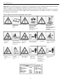
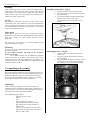
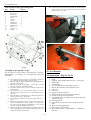
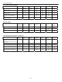
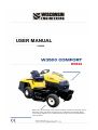
USER MANUAL
02/2008
Before the commissioning of the machine carefully read this User Manual. Always
follow the safety precautions and instructions contained in this Manual! Please
read carefully and take care to understand and comply with all recommendations
and procedures!
-1-
User manual W3532
Important: The following signs are located on your equipment or in the attached product brochure. Before
using the equipment it is important to familiarize yourself with the meaning of each sign.
If the self-adhesive label is damaged, illegible or has been removed, ask the dealer to send you a new label
and attach it in the same place as the original label (ordering numbers of self-adhesive labels – according to
the catalogue of spare parts).
Safety symbols used on the self-moving rotary cutter:
Attention!
Attention!
Read the User
Manual before
using.
Risk of injury
from flying
objects.
When cutting, the
storage vessel must be
attached or covered
against stones.
Risk of injury
from flying
objects.
Risk of
overturning of the
cutter.
Use cutter
maximally on 10°
slopes.
Risk of injury to
small children.
Remove the ignition
key before repair,
adjustment and
maintenance
and proceed according
to the Manual..
Keep a safe distance
from other persons.
Keep a safe
distance from
small children.
Type
Serial number
Year of production
Engine
Working output
Maximum output
Total weight
-2-
Attention! Before repair,
adjustment or
maintenance disconnect
the cable from the
spark plug
and proceed according to
h
l
Attention!
Risk of injury to
hands, feet and
fingers from
rotating blades and
leaves in the
ventilator of the
When reversing, check
the space behind the
cutter.
Keep a sufficient
distance.
User manual W3532
LAWN TRACTOR W 3532
User and Maintenance Manual
Dear Customer,
Thank you very much for choosing our product and we are sure that it will fulfil all your expectations. Please
read this Manual carefully and proceed exactly according to the instructions. By doing do, you will ensure
the optimal use and the long service life of the self-moving cutter. You will correctly use your investment.
The producer reserves the right to make any technical and commercial changes. For this reason, your selfmoving rotary cutter may report some small differences compared with this Manual without change to the
principal properties and the manner of operation of the machine.
Design of the machine
The machine is designed for cutting grass on treated areas of city greenery, sports sites, recreational areas,
etc.
CONTENTS
1. Regulations concerning the protection and safety of health during work ...................................................... 3
2. Marking and technical service........................................................................................................................ 4
3. Unpacking and assembly ................................................................................................................................ 5
4. User Manual ................................................................................................................................................... 6
5. Maintenance.................................................................................................................................................. 14
6. Lubrication plan – Fig.25 ............................................................................................................................. 21
7. Basic specification and technical data for self-moving rotary cutters from the W3532 series .................... 22
8. Electrical connection diagram – Fig.26........................................................................................................ 23
9. Maintenance of accumulator ........................................................................................................................ 25
10. Values of noise emissions and vibrations................................................................................................... 26
11. Recycling .................................................................................................................................................... 26
1. Regulations concerning the protection
and safety of health during work
Self-moving cutters of the W3532 series for cutting grass are
produced according to the valid European safety standards.
For the W3532 model, the cutting mechanism is mounted with
a swath of 1220 mm.
The symbol
at the beginning of the text indicates
regulations concerning safety. Labels located on several areas
of the self-moving rotary cutter are an integral part of the
safety regulations and must not be removed or erased under
any circumstances.
In the interest of security and the safety of other persons, keep
to the principal regulations for correct use as mentioned below.
-3-
User manual W3532
6) If the self-moving rotary cutter is not used for cutting
grass, it is necessary to disconnect the blades and to
lift the cutting mechanism to the highest position.
7) The transport of persons is forbidden.
8) Before each use it is necessary to check that the
blades are firmly tightened and sharpened.
9) Before starting work, the working area must not
contain other items, such as stones, branches, etc.
10) It is possible to use the self-moving rotary cutter for
cutting only in the case that the bin for cut grass or the
cover against stones are connected.
11) During cutting there must not be any persons or
animals within the range of the working area.
12) It is permitted to use the self-moving rotary cutter on
slopes with a maximum 10°(17%).
13) Each time you remove cut grass from the bin, the
drive of the cutting mechanism must be disconnected
and it is necessary to wait until the blades have
stopped.
14) Do not make any intervention into the engine for the
purpose of increasing the output and the revolutions.
15) Before getting off the self-moving cutter it is
necessary to disconnect the drive of the cutting
mechanism and to wait until the blades have stopped.
Remove the key from the ignition before leaving the
machine unattended.
16) During breaks which are necessary due to health
reasons, the employee must not be affected by the
excessive noise and vibrations.
17) In the case of professional use (or in the case of
exceeding the maximum time of exposure according
to point 15), it is necessary to submit to the
respective body of the hygiene service, the
proposal for the specification of work as risky
work in terms of noise and vibrations.
18) Near residential buildings the machine can only be
operated between 6:00 a.m. – 6:00 p.m.
Important!
Responsibility
1) Persons under 18 and any person who do not fulfil the
conditions of operation are not permitted to use the
self-moving rotary cutter.
2) The user is responsible for any damage caused by a
third person during the unauthorized operation of the
machine.
3) The self-moving rotary cutter must be used in the
respective manner for the purposes stated in this
Manual. Each misuse has the consequence of the
expiration of the warranty and the rejection of the
responsibility of the producer.
4) The self-moving rotary cutter is equipped with a
series of micro switches and safety equipment into
which it is not permitted to intervene. This would
lead to the expiration of the warranty and the rejection
of the responsibility of the producer.
5) The self-moving rotary cutter must not be used on
roads (1st, 2nd and 3rd class roads and highways).
Transport to the working place is possible, e.g. on the
trailer of a private car or tractor.
Safety rules during operation
1) Wear appropriate clothes and shoes
2) The self-moving rotary cutter is to be activated in a
clear or well ventilated area. Burnt exhaust gases are
toxic!
3) Attention! Do not activate the cutting mechanism
of the self-moving cutter in the lower position.
Before activation lift the cutting mechanism
minimally into the 3rd position of the lifting lever
of the cutting mechanism; then lift the drive of the
cutting mechanism or you can lower the cutting
mechanism into the lowest position.
4) Add fuel only the engine is switched off in clear or
well ventilated premises. Fuel vapours are explosive!
5) Do not manipulate with fire and do not smoke
near the tank.
ATTENTION!
When working with the accumulator, keep to the safety
precautions of the producer.
The electrolyte in the
accumulator is a caustic agent.
Safety rules when the machine is disconnected
and during maintenance
1) Never leave the ignition key within the reach of
children and unauthorized persons.
2) Repair, maintenance, treatment and cleaning can be
performed only when the ignition key has been
removed from the ignition box.
3) Sharpen both blade edges and take care with the
balancing of the blades.
4) Deformed or damaged blades must be replaced and
must not be repaired. Use only original brand
knives.
2. Marking and technical service
-4-
User manual W3532
Marking
Each self-moving rotary cutter is delivered marked with a
name-plate which contains the most important data and the
serial number. The serial number and the year of production
must be stated in the case of each request for technical service
and for each order of spare parts.
Assembly of the wheel – Fig 1a
1.
2.
Mount the wheel on the exceeding shaft
Face the hole of the wheel and the shaft with
the delivered pin.
3. Fix with the hammer inside and check that it
appears on the opposite side. (We
recommend to use a cutting drift or screw
driver)
Service
This Manual contains the instructions for the control of the
self-moving rotary cutter and for the correct basic maintenance
which is performed by the user. For performing actions which
are not described in the Manual it is necessary to contact the
seller or the authorized service.
Spare parts
In the case of repair it is necessary to exclusively use spare
parts which ensure safety and replacement. Each order of spare
parts must include the serial number and the year of
production.
For spare parts it is necessary to proceed according to the
manual concerning the engine.
Warranty
Fig.1a
The warranty is provided according to the instructions in the
Warranty certificate.
For the engine warranty, the terms of the respective
producer are valid.
We recommend using only the additional equipment
which is stated by the producer of the W3532 grass cutter,
otherwise there is a risk of the expiration of the warranty. The
possible connection of the other additional equipment must be
consulted with the producer!
Attaching the seat – Fig.1b
a.
b.
c.
Attach the braces into the hole of the seat
console (1).
The seat is placed onto the seat catchers (2)
on the machine.
Place and tighten the bolts in position (3) and
connect the switch of the seat by attaching
the connectors on the outlets of the switch.
3. Unpacking and assembly
Due to the storage and transport, some construction groups of
the self-moving rotary cutter are not assembled directly in the
production plant but during the commissioning. The client
must inspect the completeness of the machine. It is necessary
to proceed according to the following instructions:
Unpacking
After removing the package it is necessary to check all
individual parts of the machine and the freely packed parts. It
is also necessary to take care to prevent damage to the cutting
mechanism when removing from the palette.
The standard package contains:
- self-moving rotary cutter
- wheel
- seat
- parts of the grass storage bin
- bag with documents and User Manual
- bag with pin for securing the wheel, 2
ignition keys
- 1 spare 10A, 40A fuses and 1 spare bulb
- parts for the assembly of the seat 2 bolts, 2
braces, 2 pads, 2 nuts.
Fif.1b
-5-
User manual W3532
10. Insert the bar of the fork lifting cylinder into the hole in the
upper cap of the storage bin and secure the fork with the
flexible arrester. Fig. 2b)
List of parts of the grass storage bin
Pos:
Name
1
2
3
4
5
6
7
8
9
10
11
12
bin cover 1
front frame
bottom frame
brace I.
brace II.
curtain
bolt M6x10
bolt M6x16
bolt M6x20
plate 6 8
plate 6.4 2
nut M6 4
Pieces
1
1
2
2
1
2
6
4
Fig.2a
Fig.2
Fig .2b
Assembly of storage bin – Fig.2
For the transport of the machine, the storage bin is partially
disassembled. To assemble, we recommend the following
procedure:
1.
2.
3.
4.
5.
6.
7.
8.
9.
4. User Manual
4.1 Operation – Fig.3a, 3b, 3c
The assembly of the storage bin is performed according to
Fig. 2 and the list of parts of the grass storage bin.
Place the paper from the package of the cutting machine on
the table or the ground.
Place the cap of the storage bin pos. 1 on the paper. Spread
the fabric for the easy assembly of bolts.
Screw the curtain to the cap pos.6. Push the curtain to the
cap to the stop.
Screw parts. pos. 5,4,2, so that the free ends pos. 5,4,2, are
approximately in the area. For pos. 4 and 2 the holes are in
one axis.
Place the frame of the bottom pos.3 with the feet to the free
ends of positions 5,4,2,. Then screw.
Lift the fabric and insert the locks of the fabric into pos. 2
and 3.
Before the placement of the bin on the self-moving rotary
cutter we recommend to set the guiding “V” (obr.2a) into
the position approximately perpendicular to the ground
(with the switch for lifting the storage bin).
Place the storage bin on the guiding according to Fig.2 and
check the tightening of the fabric and the placement of the
storage bin in the closed position!
-6-
1.
2.
3.
4.
5.
6.
7.
8.
9.
10.
11.
12.
13.
14.
15.
16.
17.
18.
Wheel
Panel
Pedal for forward and backward travel – travel pedal
Brake pedal
Parking brake
Level for regulation of the height of the cut.
Bolt for disconnection of the hydraulic travel
Gas lever
Choke rod
Ignition switch (switch box)
Switch for the drive of the cutting mechanism
Switch for tilting of the storage bin
AUT-MAN switch –switching between automatic and
manual operation
Start signal lamp
Signal lamp for activation of the cutting mechanism
drive
Brake activation signal lamp
Full storage bin signal lamp
Motor-hours counter – speed indicator – maintenance
indicator
User manual W3532
19. Switch for lifting front hanger (only for request with
front hanger W3532 - Y0418)
VNÁDRŽE = approximately 7 litres
Cleaner for the hydraulic system – Fig.5
During the replacement of the cleaner it is necessary to
discharge the oil from the hydraulic system according to Fig.5a
by discharging hole “H”. After discharging the oil, unscrew
the cleaner and replace it.
Fig.3a
Fig.5
3
4
7
Fig.3b
Fig.3c
4.2 Preparation before commissioning
Fuelling
Hydraulic system – Fig.5
Regularly check the oil level in the hydraulic tank according to
Fig.5. M8AD MOGUL SUPER (MOGUL SUPER 15W50)
motor oil is required
-7-
Fig.5a
User manual W3532
spaces between the cap and the switch must be cleaned from
cut grass during the work, if necessary> In the case of filling
this space with grass it is not possible to run the engine when
the bag is attached.
Due to the transport, the self-moving rotary cutter is delivered
without motor oil and fuel. Before the activation of the
engine it is necessary to fill up the engine box with oil, and
it is necessary to comply with the regulations of the Service
Manual for the engine. Measure the level of the engine oil
when the engine is disconnected which must be between the
MIN and MAX lines of measuring bar “T” Fig.5. Using the
filler, fill up the tank with fuel and take care not to over-fill the
fuel. The tank holds approximately 9 litres The type of fuel
and oil which are to be used are stated in the service manuals
for the engine.
Checking the blades
Check that the blades are well sharpened and whether the
respective hubs are reliably fixed. Incorrectly sharpened
blades can upland the grass and cause yellowing of the
lawn.
4.3 Commissioning
Inflation of tyres
The correct inflation of the tyres is the basic precondition for
levelling the cutting mechanism and for the achievement for
proportionally cutting the lawn.
Before inflation it is necessary to remove the cover and
connect to the valves the pressure air pump equipped with the
pressure gauge. Due to the use of tube-free tyres, a manual air
pump is not recommended for the inflation of tyres.
Inflation of front wheels
Inflation of rear wheels
Parking brake
Braking with the parking brake is performed by pressing the
foot brake pedal, the relocation of the “P” lever in Fig.6
backwards in the direction of the arrow, releasing the brake
pedal and releasing the lever. The foot pedal remains in the
lower position. The release of the brake is performed by
pressing the brake pedal which causes the automatic release of
the braking brake and the lever “P”.
1.4 bar
1 bar
Grass bag
Place the tank on the guiding according to Fig. 2a and check
the tightening of the fabric and the placement of the bag.
Rear axle – Fig.5b
The axle is filled with 0.8 L of PP90 oil.
Filling hole -1
Discharging hole -2
Check hole -3
Note: In the case of the correct height of the level, the oil will
start to discharge from the stable axle from the open check
hole.
Fig.6
Fig.5b
Important!
The bag or the cover against the stones controls the switch
which blocks the switching of the electromagnetic clutch for
the driving of the cutting mechanism. In the case that the bag
or the cover against stones is not connected, it is not possible
to disconnect the cutting mechanism. It is forbidden to
disconnect this mechanism or restrict its efficiency. The
-8-
V
Fig.7
User manual W3532
Disconnection of the travel drive
If it is necessary to manually move the self-moving rotary
cutter without the engine started, it is necessary to release belt
“V” according to Fig.7. When the hydro-drive is disconnected
it is forbidden to activate the engine! Therefore, after
relocation, immediately tighten the bolt again.
Adjustment of the seat
The adjustment of the seat is performed by means of lever
“S” according to Fig.7a.
Fig.8
Description of Fig. 8.
“0” OFF
“1” Lighting, running of engine
“2” Running the engine, without lighting
“3” Start engine
Note
If during the starting of the engine there are any problems,
do not start the engine because there could be discharging
of the accumulator and overheating of the engine. Return
the ignition key to the position “0”, wait several seconds
and then repeat the procedure. If it is not possible to start,
read the instructions in the User Manual for using the
engine.
Fig.7a
Activation
Important!
Important!
It is permitted to run the engine in the open air or a well
ventilated room. Remember that exhaust gases from the
engine are toxic.
Before the activation of the engine it is necessary to perform
the following operation:
1. Brake pedal – press into the braked position.
2. Switch for activation of blade drives – position OFF.
3. Choke rod – draw up outward = position START
Gas lever – in position MIN.
4. During starting, take care to correctly insert the
key to prevent its breaking! Insert the key into the
ignition box (Fig.8) and turn it into position “1” (the
current circuit is activated)
5. Turn the key into the START position for starting
the engine. After activation release the key. Insert the
control lever of the choke into the initial position.
In the case of activation with a warm engine it is not
necessary to use the choke (START position).
If the accumulator is discharged do not use cables for
starting, this could destroy the electrical installation!
Disconnect the accumulator from the electrical installation
of the cutter and charge it with the charging device.
After the termination of work it is necessary to regularly
check the level of electrolyte and the status of charging of
the accumulator, minimally 1 x in a month. If necessary
charge the accumulator, otherwise there is the risk of
damage. We recommend removing the accumulator from
the machine and placing it on a dry, hot place.
It is necessary to make sure that the security measure does
not prevent the starting of the engine, such as:
- the machine is not braked
- the drive of the cutting mechanism is ON
Travel (Fig.3b, pos.3)
The travel of the machine is controlled by the travel pedal
which is located on the right side of the platform. The fluency
of the driving is controlled by the fluent control of pedal.
front (wider) part of pedal - driving in forward
direction
rear part of the pedal – driving in backward
direction
-9-
User manual W3532
To stop the machine release the travel brake, press the
brake and consequently always secure the machine with
the parking brake against the unwanted travel of the
machine.
Before driving release the parking brake.
4.4 Cutting grass
Attention! Do not activate the cutting mechanism of the
self-moving cutter in the lower position. Before activation
lift the cutting mechanism minimally into the 3rd position of
the lifting lever of the cutting mechanism,Fig.9; then lift
the drive of the cutting mechanism or you can lower the
cutting mechanism into the lowest position.
Fig.9
The producer recommends keeping this setting!
If you relocate the supporting wheels of the cutting mechanism
into the upper position and the lever for the lifting of the
cutting is in the 1st position, you will achieve the maximum
cutting of the grass.
Activation of the driving of the cutting
mechanism and the travel of the machine
If the self-moving rotary cutter is on the grass which is to be
cut, then it is necessary:
1. to set minimally the 3rd position of the lifting cutting
mechanism
2. to activate the drive of the cutting mechanism by
switching the switch on the panel of the machine
3. to set the required position of the lifting cutting
mechanism
4. as described above in the “travel” chapter, fluently
move the machine
Important!
The machine is equipped with automatic checking of the
contents of the bag. (This means that when the bag is full
there is the automatic disconnection of the electromagnetic
clutch of the drive for the cutting mechanism). The automatic
check is activated by the AUT-MAN switch (Fig.3c, position
13), switching to the AUT position. (When switching into the
MAN position there is the disconnection of the automatic
checking). In the case of starting the drive of the cutting
mechanism and following the filling of the bag, the drive of
the cutting mechanism is automatically disconnected. The
filling of the storage rank is indicated by the signal lamp
(Fig.3a, pos. 17). The activation of the drive of the cutting
mechanism is possible after emptying the bag. (In the case of
cutting in the MAN position, the bag is filled more than in the
AUT position, however, the any further cut grass remains on
the lawn. The use of the MAN position requires a skilful
operator!)
Note: In practice, experienced employees use both positions.
After automatic filling of the basket and disconnection of the
cutting machine, they switch to manual control and the
complete cutting of the estimated strip of the lawn during
which the channel is not overfilled. This reduces the number
of overflows of the tanks and driving to the place of emptying.
Important!
To prevent the increased wearing of belts of the drive of
the cutting mechanism, it is recommended to switch to the
cutting mechanism with adjusted gas lever in the central
position.
Fig.10
Setting the height of the cut, Pic.9
Setting the height of the cut is performed by the lever “K”
(Fig.9) in seven possible positions. When changing positions
in a downward direction it is necessary to release the arrester
by pressing the button at the end of the lever.
To ensure the correct output and the proportional cut, it is
necessary to select the travel speed according to the status of
the cut grass (height and density) and the moisture of the lawn.
In the case of the decrease of the speed of the engine, it is
recommended to decrease the travel speed and it is necessary
to take into consideration that good cutting of the lawn is not
achieved if the speed of the travel is too high. Always, when it
is necessary to overcome an obstacle, it is necessary to
disconnect the drive of the cutting mechanism and to lift the
cutting mechanism into the highest position.
- 10 -
User manual W3532
Slopes
Important!
In the case of the contact of the blades of the cutting
machine with stones or other items, it is necessary to
immediately disconnect the drive of the cutting machine,
disconnect the ignition and remove the key. Check
whether the blades of the cutting machines are not
damaged; also check the status of the fixation bolts of the
blades or other parts of the cutting machine. In the case of
damage, it is necessary to remove the defects by replacing
the defective part with an original part! Perform the
inspection of the cutting mechanism regularly after each
cutting!
Important!
After termination of each cutting it is necessary to check
the fabric of the bag for grass to see whether it was
damaged during the cutting. If the fabric of the bag is
damaged or worn, it is necessary to replaces it with new
fabric!
Supporting wheel, Fig.10
The supporting wheel (1) at the lowest position of the cutting
mechanism ensures the space between the soil and the edge of
the cutting mechanism. In this manner it is possible to prevent
damage to the lawn. If a change in the position of wheel is
required, it is necessary to release the securing counter-nut of
the Allen head screw (2) – of the axis of the wheel and to
relocate the bolt with the wheel into the other hole of the
holder. It is necessary to perform this operation in the same
manner for all 4 wheels when the engine of the drive of the
cutting mechanism is disconnected.
The producer
recommends keeping the setting from the production!
Do not use the self-moving rotary cutter for work on slopes
with an inclination higher than 10° (17%). In the case of a
change of the direction, it is necessary to pay increased
attention. It is necessary to take care of the fact that the wheels
must not be in contact with obstacles (stones, branches, roots,
etc.) which could result in the overturning and loss of control
of the machine. During working on the slope, use only the
lower travel speed.
After stopping the machine on the slope, always secure it
with the parking brake!
Emptying the bag
Never leave the bag until it is full in order to prevent blocking
of the throwing piping.
During the emptying of the tank:
1. disconnect the drive of the cutting mechanism using
the switch on the panel
2. decrease the revolutions of the engine
3. empty the bag
To control the movement of the grass bag, it is possible to use
the switch (Fig.3c, pos.12). The bag is tilted by pressing on the
lower part of the switch; by pressing on the upper part of the
switch the bag returns to the initial, closed position.
Tilt the bag only when the engine is running and the drive
of the cutting mechanism is disconnected!
Disconnection of the grass bag
The disconnection is performed according to Fig. 2b, 2a.
Remove the flexible pin and draw out the fork of the lifting
mechanism from the cup of the bag. Catch the grass bag at the
handles and draw out the guiding of the grass bag from the
guiding of the self-moving rotary cutter.
The disconnection or connection of the grass bag is performed
only when the drive of the cutting mechanism is disconnected!
Safety system
Cutting of the lawn with the self-moving rotary
cutter
1.
The longitudinal cutting in combination with the cross
cutting contributes to the achievement of a better
appearance of the lawn.
2. In the case of blocking the transport channel it is
recommended to decrease the speed of the travel
because it may be too high due to the status of the
lawn. If this problem is not resolved, the reason will
be incorrectly sharpened blades, a deformed profile of
the cutting nose or the sealed and air tight fabrics of
the bag.
3. If the grass is too high, it is recommended to cut it in
two phases. First of all, with the cutting mechanism at
the maximum height or the lower speed, then at the
required level.
4. It is necessary to pay special attention to cutting near
brushes and kerbs. As a consequence of the contact
with the obstacle, the distance between the blades can
change as well as the sides of the body of the cutting
mechanism and the height of the cutting may change.
The safe work of the self-moving rotary cutter is ensured by
the system with three protective switches.
The switches are controlled by:
- brake pedal
- seat
- bag or cover against stones
The engine can only be run only when:
- the machine is braked
- the drive of the cutting mechanism is OFF
When the engine is started it is possible to release the brake
only in the case that the operator is sat on the seat. Otherwise,
the engine is stopped. In the case of the fulfilled conditions for
the operation of the engine, it is possible to activate the drive
of the cutting mechanism only in the case that the bag or the
cover against stones is attached.
Switching the lights on
According to Fig.8 and the description in Fig.8.
- 11 -
User manual W3532
Important!
For the protection of electrical installation:
1. prevent the replacement of the polarity!
2. do not activate the self-moving rotary cutter without
the accumulator!
3. do not use starting cables to start the machine!
Termination of work
After termination of the cutting, it is necessary to disconnect
the drive of the cutting mechanism and to lift the cutting
mechanism to the highest possible position. Brake the selfmoving rotary cutter and secure it with the parking brake,
disconnect the engine, put the ignition key to the “0” position.
Before the disconnection of the engine, leave the gas lever for
about 20 seconds in the position for minimum revolutions on
order to prevent back shock.
connect a rotary sweeping brush, a rotary snow plough or a
plough iron.
The suspending equipment in pos. “Z” Fig.11a is
mounted on the self-moving rotary cutter by means of 2 pins,
pos. “C” and 4 clips. The actuator of the lifting “A” is
mounted on point “U” directly on the pin welded onto the
frame by means of the 2 draw bars of hinge “T”. The front
suspending equipment includes the hinge of the plough iron
“R” which is attached by 4 bolts, position “S”. The actuator
for the lifting of the front hinge is controlled by the switch
according to Fig.3c, pos.19.
Instead of the front suspending equipment it is
possible to connect to the front part of the self-moving rotary
cutter, bolster “N” according to Fig.11b. The bolster is
attached by 4 bolts in points “X”.
Important!
Always remove the ignition key when the machine is
unattended.
Fig.11b
Rear suspending equipment – Fig.11c
Using the rear suspending equipment it is possible to connect a
semi-trailer or other hitching tools.
The hitching equipment (1) is mounted on the rear plate of the
machine by means of 4 bolts. Using the pin (2), the eye of the
semi-trailer is connected to the equipment and is secured with
the safety arrester (3).
During the aggregation with the semi-trailer, the blades
must be disconnected in order to prevent the disconnection
of the engine due to the fact that the grass storage bin or
the cover against stones is not connected.
Fig.11c
Cover against stones DKK-572
The cover against stones (1) enables to cut grass using the
cutter without the need of the bag. It directs the stream of
grass and as a safety element it prevents the flying of stones or
other solid pieces.
Fig.11a
Front suspending equipment
Upon request it is possible to deliver the front suspending
equipment (Fig.11a), which by using makes it possible to
- 12 -
User manual W3532
2. Setting the timer for maintenance
Press and hold button S2 for 4 seconds. The number which is
in the correct position will start to flash and the SERVICE
icon will be displayed. By pressing and holding button S1 the
number will start to change. As soon as you achieve the
required number, release button S1 and press button S2 for 1
second, it will switch to the setting the next number. Repeat
the above-mentioned steps for as long as you set the service
interval. After 14-16 seconds without pressing buttons the
counter will return to the basic regime.
3. Activation of the maintenance timer
Press and hold for 4 seconds, buttons S1 and S2 at the same
time. Two numbers will be displayed for 20 seconds and then
the counter will return to the basic regime. If the engine is in
operation and the time for the maintenance achieved 0, the
service icon will appear.
4.5 Motor hours counter / speed counter –
Motor Monitor PT 14 (Fig.11e)
4. Checking the interval for maintenance
Press and hold for 4 seconds, button S2 for as long as the
remaining time of your interval appears. If you want to set a
new interval, repeat steps 4 and 5. Each time you want to see
the remaining time from the set interval, press and hold button
S2.
5. Deletion of the maintenance icon
Press and hold buttons S1 and S2. The service icon will be
disconnected. The time for the maintenance will automatically
return to the number which was previously pre-programmed.
6. Display only hours
Fig.11e
The engine monitor is an independent LCD counter for motorhours, a speed indicator and a measuring gauge for
maintenance. Energy is supplied from a lithium battery The
conductor around the sparking plug ensures both functions; the
signal of the counter for the revolutions, as well as an indicator
that the engine is running. For maintenance, this counter is
used in such a manner that the maintenance interval is set and
at the moment of expiration the counter reports the
requirement for the maintenance of the engine. Before setting
the counter each time, make sure that the engine is
disconnected. If it is necessary to unwind the black conductor
from the cable of the spark plug, for re-winding it is necessary
to perform only 3 ÷ 4 turns (otherwise the counter will not
show the correct values of the revolutions within the whole
range of the revolutions of the engine).
Press and hold button S1 for as long as 04 is displayed.
Release the button and the display will return to the overall
hours after 8-10 seconds. If the engine is in operation, the
display shows only hours, it will not display the revolutions
and the hour icon will flash.
7. Resetting the total hours and the timer for the
maintenance
Press and hold button S1 for as long as 05 is displayed.
Release the button and the display will return to total hours
after 8 seconds. Press and hold for 20 seconds, buttons S1 and
S2 at the same time, the counter will be completely reset. The
complete reset function may be excluded during production.
4.6 Cleaning and storage
After each use it is necessary to clean the self-moving rotary
cutter from the outside, to empty the bag and to shake it to
remove the remainders of grass and earth.
1. Setting the reading of the signal from the
spark plug
Press and hold button S1 for 4 seconds. LCD displays 01 (the
spark plug is activated twice per revolution), 02 (once per
revolution), 03 (each further revolution), 04 (displays only
hours not revolutions). As soon as you find the required
diagram, release button S1. The LCD will flash 8-10s and
return to the overall regime of the counter. Pre-setting of the
standard counter is 02 (once per revolution). This pre-setting
can be changed during production.
Washing – Fig.12
Washing is to be performed on a firm base with the bag
attached. Washing the inside parts of the cutter and the
throwing mechanism is to be performed with the disconnected
drive of the cutting mechanism with a stream of water lasting
several minutes or with the activated drive of the cutting
mechanism and the connection of the pressured water
gradually to both connections of the ¾” neck located on the
shell of the cutting mechanism. Then disconnect the drive of
the cutting mechanism, stop the machine, remove the bag,
- 13 -
User manual W3532
empty, wash and attach it again on order to be dried very
quickly. If there are any reminders of grass on the walls of the
bag, it is necessary to clean it so that the material can breathe.
Wash the plastic parts of the body with water and a sponge
dipped in washing detergent and pay attention so that the
engine and parts of the electrical installation are not in
contact with water.
Fig.13
Gearing – Fig.14
Fig.12
Never use a high-pressure cleaner or aggressive detergent
for washing the body, engine and electric actuator.
After 5 hours of operation of the machine, adjust the free
gearing by turning the accessible pin downward from the
machine. Using the pin (1) it is possible to turn after loosening
the two nuts (2). After setting the clearance of the nut, fully
tighten.
If these principles are not complied with, there is the risk
of the expiration of the warranty.
Storage and not using the machine for long
periods
Store the self-moving rotary cutter in a dry place protected
against atmospheric influences and cover it, if possible. If the
machine will not be used for a long time (longer than one
month) it is necessary to disconnect the red cable from the
accumulator and follow the instructions in the Manual for the
engine). Emptying the fuel tank
Regularly check that the voltage in the accumulator has
not decreased below 12V. Charge it, if necessary
5. Maintenance
Fig.14
Engine
Important!
With respect to the protection of the environment, take
care to prevent the escape of oil, fuel or other harmful
substances.
All repairs, maintenance and treatment of the machine is
to be performed when the engine is not active when the
ignition key is removed.
Front axle - Fig.13
After five hours of operation, tighten the bolt (1) on the arm of
the left vertical pin. The bolts (2) serve for setting the
clearance of the front axle in the frame.
Proceed according to the instructions of the Service and
Maintenance Manual (air cleaner, fuel cleaner, replacement of
oil, cleaning of ignition sparks, etc.).
The engine oil is discharged into the prepared vessel by
unscrewing cap “Z” on the discharging hole Pic.14. During
the replacement or discharging of oil always hold the neck
of the discharging tube with an hexagonal wrench, so as not
to loosen the tube when removing the cap! Otherwise there is
the risk of the unwanted escape of oil!
Electromagnetic clutch – Fig.15
The clearance between the rotor and the body of the
electromagnetic clutch must be within the range 0.35-0.5 mm
(the higher value is for summer operation). The adjustment is
performed by tightening (loosening) the 3 bolts position 1
Fig.15.
- 14 -
User manual W3532
F = according to a table
Fig.15b
Fig.15
Adjustment of brakes– Fig.15c
Adjustment of the belt for the pump driveFig.15a, 15b
Tightening of the belt for the pump drive is performed by the
shift of the complete pump (position “1”) in the grooves of the
pump consoles.
1. Adjustment of air brake valve
The adjustment of the brake valve is based on the
adjustment of the clearance between the brake plates and
the disk of the brake. It is adjusted with the released
terminal of the draw bar of the brake when the joining
spring does not produce any force on the level of the air
brake valve. The clearance is decreased by screwing the
pocket of the axis into the body of the air brake valve. (On
the contrary, during the unscrewing it is increased). The
correct clearance is achieved at the angle of the deviation
of the lever of the air brake valve from the neutral position
to the contact of the brake plates on the disk within the
range 15-20o.
2. Adjustment of the draw bar of the brake:
After the adjustment of the air brake valve, there is the
adjustment of the draw bar of the brake by the relocation
of the terminal on the draw bar and its securing by the nuts
in such a position where the join spring is tensioned and
slightly “wheezes” in the holes of the lever and the
converter.
Fig.15a
Procedure:
1. Loosen 4 securing bolts of the pump (position “3”) so
the pump can freely move at the ends.
2. By symmetric pushing of the pump from the frame by
means of two pressing bolts (position “2”), tighten
the belt. Proceed according to Fig.15b and the
Table. (Note: A low tightening force may cause
skipping of the belt pulley teeth in the case of large
loads)
3. In the correct position, 4 securing bolts of the pump
are tightened.
4.
CHECKING THE CORRECT TIGHTENING OF THE
BELT
Deflection force for 10
New belt
Work belt
mm bend – see
185
–
203
N
129
– 148 N
Fig.15b
Fig.15c
- 15 -
User manual W3532
Description of Fig. 15c
1. Air brake valve
2. Pocket of the axis with hexagon
3. Air brake valve lever
4. Joining spring
5. Converter
6. Terminal
7. Draw bar of the brake
Repair of tyres
The self-moving rotary cutter is equipped with tubeless tyres.
The repair of these tyres must be performed by a professional
service.
Removing of the transport channel
Before the removing of the transport channel it is necessary to
disconnect the electric conductors on the sensor for the filling
of the bag. The disconnecting connector is located near the
sensor in the front upper part of the transport channel. By
lifting the front part of the channel, the leading locks are
released and it is possible to shift the transport channel in a
backward direction. Re-assembly is performed by following
the opposite procedure. (Note: To draw out the channel, the
cutting mechanism must be slightly lifted).
Adjustment of the neutral position of the pump
lever – Fig. 15d
The neutral position of the pump lever is adjusted by the
change of the length of the draw bar by turning ball pin "K”.
After the adjustment, it is necessary to secure the pin in the
correct position with the counter-nut.
Sensor for filling the bag
In the front upper part of the transport channel, it is necessary
to clean the free capacity of the sensor membrane from the
remainders of grass (Fig.15e) – the best is after each cutting!
Fig.15d
Replacement of lamps
Lamps are located in the sleeve with bayonet fastening which
can be removed by turning.
Fig.15e
Replacement of the fuse
The electronics and the electrical installation are protected by a
10A fuse. For locating and removing the failure it is necessary
to replace the damaged fuse with a new fuse with the same
current value. For the heating of the bag and the lifting of the
front hinge, there is s 10A fuse. The fuses are located in the
pocket located under the panel on the side of the accumulator
cover. Never use fuses with another value of the current. If
after the replacement of the fuse, the self-moving cutter does
not function, it is necessary to contact an authorized service.
Replacement of wheels
Disconnect the self-moving rotary cutter under the loadbearing part of the chassis on the part of replacement of the
wheel. The front and rear wheels are secured by the pad and
the pin. During assembly it is necessary to open the pin for the
correct placement of the cover of the axis end. The rear wheels
are mounted directly on the semi-axes of the differential
equipped with a plain key. When attaching the wheels it is
necessary to lubricate the axes with grease. In the case of the
replacement of one or both rear wheels it is necessary to take
care to keep the same diameter of the wheels or to check the
adjustment of the cutting mechanism.
Notification!
The function for the automatic checking of the filling of the
bag depends on the composition of the cut grass! For
example, in the case of cutting dense wet spring grass it is
possible to disconnect the drive of the cutting equipment in
the case that half the bag is filled. On the other hand, when
cutting autumn dry grass the grass bag can be filled to the
maximum possible volume.
Dismantling of the cutting mechanism
When dismantling the cutting mechanism it is necessary to:
1. remove the transport channel
2. readjust the cutting mechanism to the lower position
3. disconnect the belt of the drive of the cutting
mechanism
4. lift the cutting mechanism into the position “2-3”
5. disconnect the front hinge pins
6. insert into the hubs of the rear hinges the auxiliary bar
with the diameter of 12 – 15 mm, length 300 mm, by
means of which it is possible to lighten the draw of
the hinge arm. Draw out the pin to disconnect the
- 16 -
User manual W3532
hinge arm from the cutting mechanism and release the
draw of the arm. Draw out the cutting mechanism to
the left or right side. The assembly is performed in
the opposite procedure.
Adjustment of the height of the cutting
mechanism
Method of measurement and TENSION
TESTER No. 7401-0076 (possible to deliver on an
order basis)
Place the measuring preparation on the cover Fig.17 so that the
measuring device is in contact with the toothed belt – without
pressure. Shift the O ring up to the cover. Re-adjust the smaller
O-ring to the beginning of the power scale, Fig.17. Re-adjust
the greater O-ring to the required value by 14 mm, Fig. 18.
When adjusting the cutting mechanism it is necessary to:
1. place the self-moving rotary cutter on a plain area
2. set the cutting mechanism to the lower position
3. loosen the arresting bolts of the draw bars of the front
hinge of the cutting mechanism
4. set the cutting mechanism into the required position
5. tighten the bolts of the draw bars of the front hinge
Measuring
ring must be
in contact with
the tested
body
Replacement of driving belts
The power from the engine to the cutting mechanism is
transferred by means of the V-belt and the belt with doublesided teeth. The driving belts must be replaced as soon as they
start to show symptoms of wear. Use only original belts!
Reference
point
Fig.17
Adjustment of the driving belt Engine – cutting
mechanism
The belt is permanently fastened with a spring-biased pulley
and, therefore, no additional adjustment or tensioning is
necessary.
Adjustment of the driving belt for blade drives,
Fig.16
Fig.18
The tensioning of this belt is performed by the adjustment of
the nut (1) after the loosening of the bolt of the pulley (2) on
the lower side of the board (3).
A correctly tightened belt has a bend of 14 mm (in the middle
of the distance between the toothed belt pulley) with the
loading 65 N. After the tightening of the belt, tighten the
pulley bolt (2). After tightening, check the value of the
tightening of the belt.
Catch the measuring instrument at the handle (read handle) and
press against the toothed belt for as long as the O-ring is in
contact with the wall of the cover Fig.19 and 20. Remove the
measuring instrument and ascertain to which value the O-ring
was shifted on the scale in N (v kg). In the case of the correct
tightening of the toothed belt on measuring route 14 mm, you
will achieve loading of 65 N (6.5 kg).
Reference point
Move O-ring to the
reference point
Measurement
value
Fig.16
Fig.19
- 17 -
User manual W3532
Starting position
Measurement value
Fig.20
Sharpening of blades
Fig.22
An unsharpened blade tears the grass, decreases the filling of
the bag and causes yellowing of the lawn which makes the
lawn unattractive. The blades must be sharpened on both
cutting edges. In the case of dismantling the blades it is
necessary to use working gloves; firmly grip the blade and
unscrew centric bolts M12 (position 1) Fig.22 and cutting bolts
M5 (position 2). It is necessary to sharpen both cutting edges
with a grinding stone with medium graining and to check the
balancing of the blade so that the round bar is inserted in to the
central hole (Fig. 23) and balances the blade.
During assembly, take care that the buckling of the blades was
directed inside the shell of the cutting mechanism. Secure
centric blades M12 against self-loosening with the seal,
LOXEAL 55-03. Tighten bolts with a torque wrench, pos. 1 to
torque moment 80 Nm. Always, before re-mounting the blades
check the status of the shear bolts, pos. 2. Damaged shear
bolts (size M5-5S-unstrengthed) must be replaced with new
bolts (original)!
Damaged or bent blades must be replaced, do not try to
repair them! Always use the original brand of blades!
Fig.23
ATTENTION!
Blades are placed facing each other at an angle of 90° and
turn in the opposite direction. During mounting it is
necessary to keep to the following mutual position.
- 18 -
User manual W3532
Maintenance plan
SELF-MOVING ROTARY CUTTER
Working action
Before
After the
commission first 10
ing (new
hours
cutter)
After the
first 50
hours
Monthly
inspection
•
•
•
- checking the tightening of the belts
- checking the angular joints and
adjustment of the clearance for
control
- checking the function of the brake
and adjustment
- checking the inflation of the tyres
•
•
•
•
- checking the adjustment of the
travel (neutral position)
- checking the oil level of the
hydraulic system (SAE 15 W 50,
super mogul oil)
- replacement of oil in the hydraulic
system
- replacement of the insert of the oil
cleaner in the hydraulic system
- checking the vertical pins of the rear
axle
- checking the function of drivers,
safety switches, fuses and lights
- lubrication of pinion and control
segment (including bearings)
- lubrication of angular joints and
lifting pockets
- checking the status of the
accumulator
- checking the mounting of the wheel
After each 50
hours
•
•
•
After each
100 hours
After each
season
•
•
•
•
•
•
•
•
•
•
•
•
•
•
•
•
•
•
After 500
hours or after
1 year
•
•
•
•
•
•
•
•
•
•
•
•
•
•
•
•
•
•
•
- lubrication of the bowden of the gas
control and starter
•
•
•
•
•
•
•
•
•
•
•
•
•
•
ENGINE
Working action
- checking the volume of
engine oil - mogul super
15W50 (Mogul super M8AD)
- replacement of engine oil
Before
commissionin
g (new cutter)
•
After the
first 5
hours
•
- checking fuel system
(tightness, wearing)
- replacement of fuel filter
•
Weekly
checking
•
Monthly
inspection
•
After each 50
hours
•
•
•
- replacement of oil filter
- cleaning of engine air filter
After the first
10 hours
After each 100 After each
hours
200 hours
•
After each
season
•
•
•
•
•
•
•
•
- replacement of ignition
plugs
- replacement of air filter
•
•
•
•
•
•
•
•
- 19 -
User manual W3532
CUTTING MECHANISM
Working action
- checking the sharpening and
tightening of blades
- checking the tightening of the toothed
belts
- lubrication of bearings for the
clamping of blades
- checking the tightening and
adjustment of the electromagnetic
clutch
- checking for any possible damage of
the cutting mechanism
After each
cutting
After the first
5 hours
•
•
Weekly
checking
•
•
Monthly
inspection
•
•
•
•
After each 50
hours
•
•
•
•
After each 100
hours
•
•
•
•
After each
season
•
•
•
•
•
REAR AXLE
Working action
Before
After the first
commissioning 5 hours
(new cutter)
Weekly
checking
Monthly
inspection
After each 50
hours
After each 100
hours
After 500
hours of
operation
•
- replacement of oil (oil PP 90)
•
- checking the status of the driving
chain
- replacement of the driving chain
•*
* In the case of work on a hilly terrain after each 400 hours of operation.
TRANSPORT CHANNEL AND BAG
Working action
After each
cutting
- checking the function of the
automatic system for the disconnection
of the cutting mechanism (cleaning of
the channel)
- cleaning of the bag fabric
- checking damage to the bag fabric
After the first
5 hours
•
Weekly
checking
•
Monthly
inspection
After each 50
hours
After each 100
hours
After each
season
•
•
•
•
•
•
•
•
•
•
•
•
•
•
•
•
•
- lubrication of the rotary points of the
bag
- checking the function of the electric
engine for lifting (only for electric
lifting)
- 20 -
User manual W3532
6. Lubrication plan – Fig.25
Positio
n
Lubrication point
Grease
Time interval for
lubrication
1.
2.
3.
Control joints
Centric pin for front axle
Pinion and control segment
1 x in 6 months
1 x in a year
1 x in a month
4.
5.
Placement of brake pedal and travel pedal
Arresting segment of parking brake
1 x in a month
1 x in a month
4
-
6.
7.
8.
1 x in a month
1 x in a month
1 x in 6 months
1
4
-
1 x in a month
1 x in a month
1 x in 6 months
1
1
5
1 x in a month
1 x in a month
1
2
15.
Front hinge pins
Lubrication
grease
Oil SAE 30
Oil WD-40
Lubrication
grease
PP90
Lubrication
grease
Oil SAE 30
1 x in 6 months
13.
14.
Wire for the control of gas and the starter
Hinge joints for the cutting mechanism
Rotary plate for the level of lifting of the cutting
mechanism
Arresting segment of the level of the cutting
mechanism
Placement of the draw bar for tilting of the bag
Chain gear
Pins in the draw bars of the brake system, including
the brake axis
Rear axle gearbox
Joint and pin for travel control
Oil SAE 30
Oil SAE 30
Lubrication
grease
Oil SAE 30
Lubrication
grease
Oil SAE 30
Oil SAE 30
Oil SAE 30
Number of
lubrication
points
4
2
-
1 x in a month
8
9.
10.
11.
12.
Fig.25
- 21 -
User manual W3532
7. Basic specification and technical data for self-moving rotary cutters from the W3532
series
W3532
Engine
Producer
Output
Alternator
KOHLER COMMAND
22 HP
12V/15A
Cutting mechanism
Cut
Number of blades
Manner of turning
Height of cutting
Disconnection of the drive
Collection of grass
1,220 mm
2
contra-rotating
30 ÷ 120 mm
electromagnetic clutch with brake
rear throwing, grass bag in the rear part of the machine
Grass bag
Volume of the bag
Manner of emptying
460 l
electric
Gear mechanism
- hydrostatic, independent regulated piston hydro generator (for engine) + robust rear axle with piston
hydro-engine
- volume of hydraulic tank 7L.
Maximum travel speed
forwards
backward
13 km.h-1
5 km.h-1
Tyres
Front
Rear
Dimensions
Length with bag + front hinge
Width
Height
wheel base
wheel track
16 x 6.5 – 8
20 x 10.00 – 8
2,820 mm
1,265 mm
1,280 mm
1,280 mm
1,030 mm
Weight
435 kg
Fuel tank
Volume of fuel tank
11 l
- 22 -
User manual W3532
8. Electrical connection diagram – Fig.26
Colour distinguishing of conductors
Conductor No.
colour
Conductor No.
colour
Conductor No.
colour
Conductor No.
colour
Conductor No.
colour
1
2
3
4
5
6
7
9
9
10
11
12
13
14
15
16
17
18
19
20
21
22
23
24
25
26
27
28
29
30
31
32
33
34
35
36
37
38
39
40
41
42
43
44
45
46
47
48
49
50
51
52
53
54
55
56
57
58
59
60
61
62
63
64
65
66
67
68
69
70
71
81
82
83
84
85
86
88
89
brown
red
black
black
black
black
black
black
black
black
black
black
red
orange
violet
blue
blue
white
white
white
brown
brown
brown
brown
brown
brown
brown
red
green
purple
white
black
brown
red-white
red-white
blue
brown
red
black
blue
blue
brown
brown
blue
yellow
yellow
yellow
red-black
red-black
brown
white
white
red
red
blue
blue
brown
brown
brown
brown
green
green
green
brown
purple
brown
grey
grey
brown
blue
brown
red
List of devices
1. Accumulator12 V
2. Starting solenoid
3. Engine
4. Fuse 10 A
5. Switching box
6. Fuse 40 A
8. switch cutter - start
9. Switch AUT – MAN
11. Check lamp - START
12. Check lamp manual brake
13. Check lamp cutter
14. Check lamp for blocking the bag
16. Micro switch for filling the bag
17. Seat switch
18. Switch manual brake
19. Switch for bag hinge
21. Front lights
22. Counter for motor hours / revolution meter
23. Electromagnetic clutch
24. Auxiliary relay seat
25. Auxiliary relay seat + brake
26. Auxiliary relay manual + brake
27. Auxiliary relay bag
28. Auxiliary relay automatic system
29. Auxiliary relay for tilting of the bag
32. Switch for tilting of the bag
34. Accumulator for heating of the bag
40. Fuse 40A
41. Auxiliary relay – front hinge
42. Switch for lifting the front hinge
43. Actuator for lifting the front hinge
Note: Indication of devices in the diagram (Fig.26) -
- 23 -
red
yellow
green
red
black
brown
brown
User manual W3532
Obr.26
- 24 -
User manual W3532
9. Maintenance of accumulator
Safety precautions during use and installation
A 12V car filling accumulator is used. The electrolyte is completed in the production plant and is charged to
the required capacity of 32Ah.
The filling and adding of electrolyte must be performed by professional service.
ATTENTION!
Important:
After termination of the work it is necessary to regularly check the level of electrolyte and the status of the
charging of the accumulator, minimally 1 x in a month.
If it is necessary (difficulty in starting, decrease of intensity of lighting, etc.) to charge the accumulator,
there is a risk of its damage.
After termination of seasonal work we recommend removing the accumulator from the machine and to place
it in a dry warm place.
Charging of accumulator
Before charging, dismantle the filling cap and check the level of electrolyte. If you ascertain a small decrease
in the level of electrolyte, it is necessary to add distilled water up to the “UPPER LEVEL”.
In the case of a large decrease in the level, contact a professional service.
Charge the accumulator by the maximum current 3A. Charge until the accumulator starts to boil and the
specific density of electrolyte exceeds 1.27.
Installation
Fix the accumulator firmly into the machine. Make sure that the positive and negative poles of the
accumulator are connected correctly.
Maintenance of accumulator
1. Once a month check the level of electrolyte.
2. Use distilled water for renewing the level. Never use electrolyte for increase the level.
3. Always keep the accumulator clean.
- 25 -
User manual W3532
10. Values of noise emissions and vibrations
Engine
Level of acoustic pressure in the place of operator dB (A)
Guaranteed level of acoustic output dB (A)
Weighted effective value of acceleration – seat (vertical vibration)
m.sec-2
W3532
Kohler Command 22 HP
87,2
103
1.0 m.s-2
Weighted effective value of the acceleration of vibrations transferred to hands– left hand
right hand
Conditions for measurement:
- revolutions of cutting equipment
- speed of the travel
- cutting of the grass at medium height
2.7 m.sec-2.
3.5 m.sec-2.
2500 ot.min-1.
5.4 km.hod –1.
30 mm
11. Recycling
After expiration of the service life, the self-moving rotary cutter must be liquidated in accordance with Act No. 185/2001 Coll., and
according to valid regulations.
Accessories for cutting mechanism W3532 – can be ordered on request
Y0417
Y0418
E5821
Y0735
E5741
F000531
E6754
bolster
front hinge
hydraulic unit DJH-590
mulching set
cover against stones DKK-572
snow chains
tractive hinge
Working tools for cutting mechanism W3532 – can be ordered on request
B3361
E5770
S0444
E7080
E7090
leaf picker ASL-611
sweeping brush AZK-612 (connection: front hinge Y0418 + hydraulic unit E5821)
snow plough SF-1050 (connection: front hinge Y0418 + hydraulic unit E5821)
plough RS-110-35M – mechanical lifting
plough RS-110-35E – electric lifting - (connection: front hinge Y0418)
- 26 -
User manual W3532
02 - 2008
WISCONSIN Engineering CZ, s.r.o.
Vrahovická 41, 796 02 PROSTĚJOV,
Tel: 582 401 915 Fax: 582 401 919
E-mail: [email protected]
www.wisconsineng.cz
- 27 -