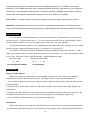
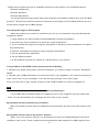
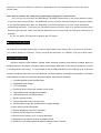
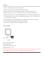
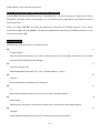
1
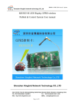
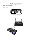
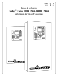
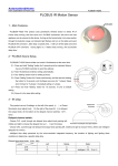
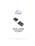
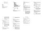
CAMBER PANEL SWITCH
How does PLCBUS work:
Powerline Communication Bus (PLCBUS) is a highly reliable, cost effective, 2-way communications
technology which enables control products to utilize existing powerlines for both residential and commercial
applications. The most main feature of PLCBUS Technology is no any Filter and block necessary.
1. Modules: These components will receive PLCBUS signals and will switch or dim the attached lamp
or appliance, and then feedback current status.
2. Controllers: These components will transmit PLCBUS signals and thus will control the Modules;
2-way Communications.
3. Transceivers: Wireless components like remotes (433.92MHz). The signals of these components
will be received by a controller with transceiver functionally (PLCBUS-T 4023UK). The Transceiver
will translate the signals into PLCBUS signals on the power line.
PLCBUS Features:
Highly Reliable -The PLCBUS method of communication is 100 ~ 1000 times more reliable than current
X-10 technology and 10 ~100 times more reliable than CEBUS or LONWORKS powerline technologies.
Reliability is defined as the percentage of transmitter/receiver pairs that correctly operate upon initial
installation. The PLCBUS test units are randomly installed in the environment typical of the target market.
This market is defined as the single-family residential market in China. This environment is defined to be
the existing base of homes, without any modifications. This means that there should be no “fixing” the
electrical system of the residence by adding repeaters or filtering. The first version of PLCBUS will be over
99.9% reliable (>100 times X-10). Current X-10 is around 70%~80%.
No New Wires – 100% powerline communication, no new wires.
Higher Speed – 20 to 40 times the speed of X10 in terms of data transmitted. This is equivalent to over ten full
commands per second. The average latency of command to action is less than 0.1 second.
Two Way Communications – Hardware, software and protocol design allow for two-way communication in all
products.
House Separation – Multiple houses on one transformer will be separated by means of an addressing
scheme allowing totally 64,000 different addresses.
Interaction – PLCBUS communication can be used in the presence of all X-10, CEBus, or LonWorks
1/17
compatible equipment with no interference between PLCBUS equipment or X-10, CEBus, or LonWorks
equipment. The PLCBUS technology uses a completely different frequency range than any of the wide-band,
narrow-band, or spread spectrum technologies. The physical method of PLCBUS communication is entirely
different than the modulation-demodulation techniques of all X-10, CEBus, or LonWorks.
Peer to Peer – No central controller necessary for single point-to-point control or group (scene) control.
Simplicity – the PLCBUS solution uses “off the shelf” components for transmission, receiving and control
circuits, including standard microprocessors. No ASIC’s (application specific integrated circuits) are necessary.
64000 Addresses:
You can select up to 256 addresses by code set electronically. Each address is dividing into a
House Code (A – P) and a Unit Code (1 – 16). On control the House code is also selectable. When
Modules and Controllers are set to the same House Code, they will work together.
The PLCBUS System contains many standardized commands where by modules set to the same
House Code will respond simultaneously (e.g. All Lights On, All Units Off).
For installer: To different families, PLCBUS also provide additional 250 User Codes (1 – 250).
When you install for many houses in the same building, for each family, you should set a different User
Code. Thus, 250 User Codes x 256 Addresses = 64000 Addresses totally.
250 User Codes
x
(1…250)
(For 250 different families)
256 (House/Unit Codes)
(A…P / 1…16)
(In each family)
Signal Range:
Range of radio signals
Many of the wireless components of the PLCBUS program use radio signals (433.92MHz).
Examples are remotes and wireless sensors. The range of these radio signals depends on:
1. The number of walls and floors the signal will have to pass through and the material used in these
walls and floors.
2. Other wireless Transmitters which use the same frequency will influence the range. Please see
interference.
3. Distortion by radio fields from micro processors and satellite equipment. When you move your RF
PLCBUS products away from this kind of device, the range can be improved significantly.
4. The number of people between RF Transmitter and Receiver.
Interference
When more devices are using the same frequency to communicate, the range of those products
will decrease significantly because of the distortion of the signals used. Please find the list below of
2/17
known devices which will have an important influence on the range of your PLCBUS products:
Wireless Headphones
Wireless Speakers
Wireless Baby Phone
You will get the best range results when these sources are switched off while using your PLCBUS
products. The products mentioned will have influence on the range of the PLCBUS Products, but will
not be able to trigger the PLCBUS System.
Increasing the range of radio signals
When the range of your remote is insufficient you can try to increase the range by following the
suggestions below:
1. Check whether you have fixed the PLCBUS4023UK (Transceiver Module)?
2. Are there any devices switched on which can cause interference?
3. Try to increase the range by moving the Transmitter or Receiver (a few centimeters can make a
huge difference!).
4. Remove Transmitter and Receiver away from big metal objects.
5. Are the antennas fully extended?
6. Are the batteries fresh?
7. Is the #4023UK Transceiver located at a central place in your house?
If any problem on PLCBUS control, please note the following:
1. Whether your power line system is exceed one phase, you need to install a “Coupler”, #PLCBUS
4825E.
2. Whether your PLCBUS controller can control the units in your neighbors, you must have forgotten to
learn” User Code” of your controllers. It can be solved by learning “User Code” again.
And if you still have no way, please contact to local PLCBUS dealer or e-mail to [email protected].
FAQ:
What is the reason for modules to switch on/off spontaneously?
It is possible that a PLCBUS System is installed at one of your neighbors using the same User
Code. To solve this problem try to change the User Code of your system.
My modules will not respond to my controller?
Make sure that the House Code on all Modules and Controllers are set to the same House Code
(A-P).
My modules will not react to my remote / Sensor?
When you use a remote or sensor, you should have at least one PLCBUS4023UK Transceiver
installed in your house. These components will translate the radio signals to PLCBUS signal on the
3/17
power line. Only one Transceiver should be installed for all remotes and sensors set to the same
House Code.
Am I able to increase the range of my remotes by using more Transceivers?
Yes, you can use more than one #PLCBUS-T 4023UK Transceivers in your home when the range
of your remotes is not sufficient. The #4023UK is using so called collision detection to prevent signals
to be disturbed when more than one #4023UK Transceiver will wait for a quite power line before
transmitting their data. To prevent your PLCBUS System to become slow or to prevent dimming from
becoming less smooth, make sure that the #4023UK units are placed as far away from each other as
possible.
Or you can add a RF Repeater to amplify the RF Signal.
★ Leaving Factory Default:
All products in PLCBUS System are “1-Phase” Status when leave factory. So if you use it in “3-Phase”,
you need to setup it to “3-Phase”. Firstly, setup all the controllers to “3-Phase”, then go to other setup.
Camber Panel Switches:
Gracious artificial crystal adopted, Camber Panel Switches creatively and perfectly combine glass hot
bending technique and home automation switch panel design. Meanwhile, in this series of products, we build
in “Present sensor technology”. TFT LCD DISPLAY 240 X RGB X 320 DOTS color LCD and up to 24 pictures
storage, except the main menu, you can download your family photos, and display automatically. So Camber
Panel Switches design is more fashion and hommization. Main features as below:
1. Fantastic artificial crystal camber panel;
2. Detachable panel design;
3. TFT LCD display;
4. Receiving device names are showed in main menu;
5. Digital photos rolling display automatically;
6. Download pictures via USB connector;
7. Build-in present sensor;
8. Dimmer Switches, easy to change fuse;
9. Enhancement of Two-way communications signal strength;
10. Blue LED local On/Off indicator;
11. Enquiry Brightness Level from controller;
12. Enquiry On/Off status from controller;
13. Each receiver memory up to 16 scene addresses;
14. Brightness level memory function in different scene;
15. Electronic Code setting and main address changing from controller.
4/17
Camber Panel Switch Structure Illustration :
Button Names
Show Area
Pictures
Display
Area
Local control
buttons and
Blue indicating
Light
Detachable
Camber Panel
Backside Part
S1/S2 Key
S3/S4 Key
Camber Panel Switches Pictures Display Download Method:
Connect the USB line between camber switch and your PC, when the computer displays Figure 1, double-click
the left mouse button, and you can find the display as Figure 2; then double-click DPFMate.exe into Figure 3,
here, in the grey field of Figure 3, single-click the right mouse button, you can choose “language”, see Figure 4.
Figure 1
Figure 2
Figure 3
Figure 4
5/17
Figure 5
At this time, in Figure3, you can delete or add some pictures you have edited;
DPF Mate: Functions introduction of each button:
Turn Left/Turn Right: turnover the picture left and right;
Cut: you choose some part of the picture from DPF and then add/save it; No matter what resolution
originally, here will be unified.
+/-: Zoom In or Zoom Out the display area of picture;
Setup: you can change font color and background mode;
Add: after you choose the picture on the right, then click ADD button, the picture will be added to the
display area on the left.
Save: you can save the edited pictures to other disk;
Save All: you can save all edited pictures to other disk;
Choose Picture: you can choose and drag in the pictures you favor from your PC directly;
Choose All: click then you can choose all the pictures;
Download: after you drag a new picture into preview area, then click mouse on DOWNLOAD button,
when the progress bar below show you 100% means the picture has been copied to switch.
Delete: click then you can delete the picture till no anything on the right DPF;
Exit: you can exit this software operation interface (Page).
Main Menu Picture Function Explanation:
Main menu (The first picture) of camber receiver switches, you can edit the picture and add lights name for
indicating (Such as: Bed Room, Living Room, Wall Light, etc). The features as below:
1. If your hand moving near 15cm, the camber switches can wake-up from stand-by mode;
2. If no any operation, in 10 seconds, display area will rolling show the other 23 photos display (1 picture
each per 6 seconds, and 1 minute later enter stand-by mode), period to your hand near in 15cm range,
it also can return to main menu at once.
3. During pictures rolling show, if you click key S3 or S4, can turn to next picture by manual, and if no
clicking, 5 seconds later, it will rolling show again automatically.
6/17
Camber Panel Switches – Receivers: s:
CS820 - Camber 2.4' Single-Button Dimmer Switch
CS821 - Camber 2.4' Double-Button Dimmer Switch
Main Features:
1. Two-way communications
2. Lamp On/Off status and Brightness check
3. Respond “On/Off, All Lights On/All Units Off, Bright/Dim” command
4. Memory 16 different address for scenes control
5. LED indicating light local show lamps On/Off status
6. Dimmer and 100 Brightness levels for Incandescent lamp only
7. 1 (Main add) + 16 (Scene add), totally 17 addresses.
Installations:
◆ Switch off power.
◆ Connects according to the label on the module.
◆ Module’s “L” connects to incoming 230V ‘Line’ wire.
◆ Module’s “N” connects to the incoming 230V ‘Neutral’
◆ Module’s “1” and “2” connects to Lamps.
Main Address Setup: (Load1 and Load2 setup method is same)
1. Press key S1 (for Load1) or S2 (for Load2) and hold for 5 seconds the controlled lamp goes ‘On’, and
the 4 LED indicating lights flicker (CS821: S1-Top two LED lights, S2-Bottom two LED lights), means
enter setup status;
2. Next, release Key S1 or S2 and use main controller to send an address with ‘On’ or ‘Off’ command (e.g.
A1 ‘On’) to the CS820/821. The controlled lamp will go ‘Off’ and the 4 LED indicating lights are always
bright, means setup is successfully (CS821: Top 2 LED lights are always bright for indicating Load1
setup successfully, Bottom 2 LED lights indicates Load2).
3. To exit this setting mode, tap any control button once or there is no any action within 20 seconds; the
module will also exit this setting mode automatically.
16 Addresses – Scene Controls Setting:
1 (Main add) + 16 (Scene add), totally 17 addresses (See detail for this setup in controllers user manual).
7/17
Delete Scene Address:
Also please see detail for this setup in controller’s user manual.
Operations:
Operate manually very easy, i.e. tap left or right local control button, the lamp will be controlled ‘On’ or ‘Off’
and different from current status. (Top left and right control buttons are for Load1 and Bottom for Load2).
Lamp controlled is ‘On’, the LED indicating light will be ‘Off’, and vice versa.
Brightness adjustment: Press “left control button” and hold more than 1s is for bright, so “right control button”
is for dim. If releasing, next “On” the lamp, it will memory the last brightness level.
LED indicating lights: have 4 different brightness levels; and tap Key S1 or S2 once for one changing.
Can be remotely controlled using any PLCBUS compatible transmitter.
Accept ‘On/Off’, ‘All Lights On/All Units Off ‘and Bright/Dim commands.
Connection Figures:
#CS820: 230V±10%/50Hz – 400W max – Incandescent lamps only
#CS821: 230V±10%/50Hz– 400W in sum – Incandescent lamps only.
Load types fitted: Incandescent lamp, LED light (Resistive only)
Load types no-fitted: Non-resistive light and appliances (such as: Low-Voltage spotlight, fluorescent lamp,
appliance, etc). While if connected, will lead switches are damaged fast.
Static State Power Consumption < 1W
Dimmer switches, for security, we add fuse design, and very easy to change it;
Just open the fuse cover and then replace it is ok; (Please see figure above).
Notice: When install, you’d better take apart screen and the cover, and then plug/cover one by one, while if
8/17
they are together, and you press too much, it is easy to damage the micro button under them.
CS824 - Camber 2.4' Single-Button Appliance Switch
CS825 - Camber 2.4' Double-Button Appliance Switch
Main Features:
1. Two-way communications
2. Fluorescent Lamp and Appliance ON/OFF status check
3. Respond “On/Off, All Lights On/All Units Off” command
4. Memory 16 different address for scenes control
5. LED indicating light local show lights On/Off status
6. 1 (Main add) + 16 (Scene add), totally 17 addresses.
(See detail for this setup in controller’s user manual).
Installations:
◆ Switch off power.
◆ Connects according to the label on the module.
◆ Module’s “L” connects to incoming 230V ‘Line’ wire.
◆ Module’s “N” connects to the incoming 230V ‘Neutral’
◆ Module’s “1” and “2” connects to Fluorescent Lamps or Appliances.
“All Lights On / All Units Off” commands respond and Main Address Setup:
1.
Press key S1 (for Load 1) or S2 (for Load 2) and hold for 5 seconds the controlled lamp goes ‘On’,
and the 4 LED indicating lights flicker (CS825: S1-Top two LED lights, S2-Bottom two LED lights),
means enter setup status;
2.
Next, release Key S1 or S2 and use your controller to send a “All Lights On” command, the
controlled light will respond “All Lights On”; While send a “All Units Off” command, the controlled
light will respond “All Units Off” only, not respond “All Lights On” command;
3.
And then use your controller to send an address with ‘On’ or ‘Off’ command (e.g. A2 ‘On’) to the
CS824/825. The controlled light will go ‘Off’ and the 4 LED indicating lights are always bright, means
setup is successfully. (CS825: Top 2 LED lights are always bright for indicating Load1 setup
successfully, Bottom 2 LED lights indicates Load2).
9/17
4.
To exit this setting mode, tap any control button once or there is no any action within 20 seconds; the
module will also exit this setting mode automatically.
16 Addresses – Scene Controls Setting:
1 (Main add) + 16 (Scene add), totally 17 addresses (See detail for this setup in controllers user manual).
Delete Scene Address:
Also please see detail for this setup in controller’s user manual.
Operations:
Operate manually very easy, i.e. tap left or right local control button, the lamp will be controlled ‘On’ or ‘Off’
and different from current status. (Top left and right control buttons are for Load1 and Bottom for Load2).
Light controlled is ‘On’, the LED indicating light will be ‘Off’, and vice versa.
LED indicating lights: have 4 different brightness levels; and tap Key S1 or S2 once for one changing.
Can be remotely controlled using any PLCBUS compatible transmitter.
Accept ‘On/Off’, ‘All Lights On/All Units Off ‘commands.
Connection Figures:
Rated Voltage: 230V±10%/50Hz
Rated Current: Resistive Load: 8A
(Incandescent lamp, etc)
Electric Transformer: 5A (electronic ballast, fluorescent light, low-voltage spotlight, etc)
Inductive Load: 1.5A
(Electric fan, Air Condition, inductive ballast, etc).
Static State Power Consumption < 1W
Notice: When install, you’d better take apart screen and the cover, and then plug/cover one by one, while if
10/17
they are together, and you press too much, it is easy to damage the micro button under them.
CS860 - Camber 2.4' Shutter Control Switch
Main Features:
1. Two-way communications
2. Control motor “Turn Open” or “Turn Close”
3. Respond “On/Off” command only
4. Memory 16 different address for scenes control
5. LED indicating light local show motor turn “+” /”-“status
6. 1 (Main add) + 16 (Scene add), totally 17 addresses.
(See detail for this setup in controller’s user manual).
Installations:
◆ Switch off power.
◆ Connects according to the label on the module.
◆ Module’s “L” connects to incoming 230V ‘Line’ wire.
◆ Module’s “N” connects to the incoming 230V ‘Neutral’
◆ Module’s “1” and “2” connects to positive (“+” as below) and return aspect (“-” ) running of motor.
Main Address Setup: (Load1 and Load2 setup method is same)
1. Press key S1 (for Load1) or S2 (for Load2) and hold for 5 seconds the controlled motor turn “+”, and the
4 LED indicating lights flicker, means enter setup status;
2. Next, release Key S1 or S2 and use your controller to send an address with ‘On’ or ‘Off’ command (e.g.
A3 ‘On’) to the CS860. The controlled motor will stop and the 4 LED indicating lights are always bright,
means setup is successfully;
3. To exit this setting mode, tap any control button once or there is no any action within 20 seconds; the
module will also exit this setting mode automatically.
16 Addresses – Scene Controls Setting:
1 (Main add) + 16 (Scene add), totally 17 addresses (See detail for this setup in controllers user manual).
Delete Scene Address:
Also please see detail for this setup in controller’s user manual.
11/17
Operations:
Operate manually very easy, i.e. when motor is stopped, tap top left or right local control button, the motor
will turn “+”, and tap bottom left or right control button, turn “-“;
During motor running, if tap again for stop; and then again for continuing;
“Bright” and “Dim” buttons on controller, each tap, the curtain will be closed and opened 10cm;
Motor controlled is turned ‘+’, the top 2 indicating lights will be ‘Off’, and bottom 2 LED lights are ‘On’;
While Motor controlled is turned ‘-’, the top 2 indicating lights will be ‘On’, and bottom 2 LED lights are ‘Off’;
This LED lights status will keep 10 minutes till CS860 stop power supply to motor, the 4 LED lights will be
‘On’ all. (This design is more safety);
LED indicating lights: have 4 different brightness levels; and tap Key S1 or S2 once for one changing.
Can be remotely controlled using any PLCBUS compatible transmitter.
Accept ‘On/Off’, ‘All Lights On/All Units Off ‘and Bright/Dim commands.
Connection Figures:
Rated Voltage: 230V±10%/50Hz
Motor Controlled: 300W
Static State Power Consumption < 1W
Suitable Temperature: -10~50℃
Notice: When install, you’d better take apart screen and the cover, and then plug/cover one by one, while if
they are together, and you press too much, it is easy to damage the micro button under them.
12/17
CS810 - Camber 2.8' Simple Touch Controller
CS810 is a Crystal Camber 2.8’ LCD Scene Simple Touch Controller and the fashion design bring you very
concise and lively feeling; you can control the SCENE function visually and easy installation.
Main function features:
1. CS810: Voice indicating function when operation;
2. The screen can contain up to 24 different pages. Each page, you can edit picture according to your favor;
3. In each page, you can setup up to 18 buttons (each button size > 7 x 8mm);
4. In each button, can memory up to 16 different address and ON or OFF command, or link to some page;
5. Any each button in the display, where you tap, you can setup there freely.
6. 30seconds no operation for “Sleep” - standby Mode can save power wastage.
LCD Screen Simple Touch Area
Installations:
◆ Switch off power.
◆ Connects according to the label on the module.
◆ Module’s “L” connects to incoming 230V ‘Line’ wire.
◆ Module’s “N” connects to the incoming 230V ‘Neutral’
Button Functions Introductions:
LINK Key:
1. Press and hold for 10s till blue LED indicating lights are bright, can clean all scenes setup in
current page;
2. Tap once can turn to last page.
13/17
ENT Key:
1. Press and hold for 5s till blue LED indicating lights flicker;
A. LED lights flicker 3 times + 3 buzzers means current 3-phase status;
B. LED lights flicker once + 1 buzzer means current 1-phase status;
2. Tap once can turn to next page.
Scene Function Setup Method:
(Very important, before setup each page, this step is necessary. Because you can’t confirm whether
some place of this page have been setup scene before, so needing clean all).Press LINK Key and hold for
10 seconds, LED indicating light is bright, you can delete all command in current page.
(1). Scene Setup Method:
A). On the picture edited, any button you want to setup, press and hold for 5 seconds, the blue
indicating lights are bright, releasing now (here if no operation in 15 seconds or tap any place on
the screen for exiting automatically);
B). Then use controller send out up to 16 different address and On or Off command, each button can
memory up to 16 different addresses.
C). After memory 16 different addresses, CS810 will exit setup status automatically. (Or tap ENT key
also can exit).
(2). Dimming Buttons Setup Method:
(1). Press any button in this page and hold for 5 seconds, the blue LED lights are bright, releasing now;
(2). here you can use controller send out Bright or Dim command,
(3). after CS810 distinguish and memory, it will exit automatically. Here, the button has Bright or Dim
function.
Notice: Dimming operation: when you bright or dim daily, each tap bright or dim button, the controlled
light is the first address in last scene operated.
(3). Link to One Page Setup Method:
You can setup one button in this page with “Link to any page” function, press this button and hold for
5 seconds, the blue lights are bright, then tap LINK Key several times (how many times means link to
which page); after you setup, you can tap ENT Key for save and exit.
14/17
Technical Parameters:
Rated Voltage: 230V±10%/50Hz
Static State Power Wastage: <1W
Suitable Temperature: 0 - 40℃
Screen: 2.8 color TFT LCD DISPLAY 240 X RGB X 320 DOTS
Notice:
After installing CS810
(1). Before setup each page, please clean all of the commands in current page. (Press LINK and hold for 10
seconds);
(2). During fix or take apart CS810 need to take care and avoid of the LCD Screen fall down; If you want to
clean it, needing ensure the screen is under dormant-status. Then use clean and soft cloth to wipe the screen;
needing to notice, avoid of non-dedicated cleanser drip on the screen.
(3). When install, you’d better take apart screen and the cover, and then plug/cover one by one, while if they
are together, and you press too much, it is easy to damage the micro button under them.
Connection Figures:
16 Scene Addresses Clean All Method:
Each receiver has 16 scene addresses, except delete all from controllers (e.g. #4034E/4830E, etc), from
switches still can local delete the scene addresses, method as below:
Press Key S1 or S2 (S1 for delete 16 scene addresses of Load1, S2 is for Load2) and hold for 10s till the unit
controlled is Off, the operation is successful! (Notice: when hold for 5s, the unit controlled is On for entering
15/17
setup method, so don’t release at that time).
P16 for “All Rooms Lights On/All Rooms Units Off” Functions:
Address P16: Each PLCBUS Receiver has 1 Main address + 16 Scene addresses. When the 16 Scene
addresses still haven’t been setup totally up to 16 different scene addresses, the PLCBUS receiver
has this function.
When you press “P16-ON”, all lights and appliances controlled by PLCBUS modules in your whole
house will be On, while “P16-OFF”, all lights and appliances controlled by PLCBUS modules in your
whole house will be Off.
Announcements:
Protecting your switches, and try to let them far from:
●
A
ny kind of liquid:
Don’t let switches touch water, rain, sweat or other extreme moist surrounding, and notice never put them
into dryer, while will bring product damage.
●
E
xtreme hot or bitter cold:
Avoid temperature lower than -10℃ (14℉) or higher than 60℃ (140℉).
●
M
icrowave:
Don’t put switches in microwave oven for drying.
●
D
irt:
Don’t expose switches to dust, dirt, sand, food or other unsuitable material.
●
W
ashing liquid:
Please use dry-soft cloth to clean product surface, don’t use alcohol or other washing liquid.
●
D
rop down:
Avoid switches dropped down to ground, the panel and screen will be broken.
16/17
Warning:
▲
A
void of switch on-off frequently, it can lead controlled units damaged. Just like TV, Air Condition,
Refrigerator, etc, if switch on-off often will bring appliances perpetual damage. Damaged on this reason, it
is not in our warranty range.
▲
P
lease ensure children are far from switches, or some small parts are eaten by them.
▲
W
hen you choose controlled devices, please notice some units (such as: coffee pot, etc), if nobody at home,
and also no water in them or also notice each switch has a rated load limited, don’t exceed it, while bring
fire, manufacture doesn’t assume any economic losses.
So when installation engineer program, if control appliances, don’t setup them respond “All Lights On”
command.
Ver. 20120310
17/17