1
DEGREE PROJECT IN COMMUNICATION SYSTEMS, SECOND LEVEL
STOCKHOLM, SWEDEN 2015
USB dongles for mobile
broadband
Data communications for laptop
computers
LIU ENFEI
KTH ROYAL INSTITUTE OF TECHNOLOGY
INFORMATION AND COMMUNICATION TECHNOLOGY
USB dongles for mobile
broadband
Data communications for laptop
computers
Liu Enfei
2015-06-24
Master’s Thesis
Examiner and Academic adviser
Gerald Q. Maguire Jr.
KTH Royal Institute of Technology
School of Information and Communication Technology (ICT)
Department of Communication Systems
SE-100 44 Stockholm, Sweden
Abstract | i
Abstract
Today a growing number of people need to work on laptops with wireless Internet connection. There
are two common wireless Internet access solutions: wireless local area network (WLAN) via hotspot,
and high speed wide area cellular network via mobile broadband device such as 3G/4G Universal
Serial Bus (USB) dongle. USB dongle was the pioneer product in 3G/4G market, and it is still a
popular device in many countries. Mobile broadband can offer both high speed access and mobility.
Technically mobile broadband allows Internet connection as long as your mobile transceiver can
access your cellular network operator’s network. However, in practice the data rates experienced by a
user via mobile broadband are not comparable to the data rates that are available via WLAN.
Moreover, mobile broadband has been implemented according to multiple different standards. Hence,
in order to provide a user with locally optimal service requires that user must make use of
heterogeneous networks. Furthermore, the variety of networks gets increasing due to the emergence
of various 4G networks.
The aim of this thesis is to explore how heterogeneous networks could be exploited to provide a
user of a laptop computer with locally optimal service, while hiding the complexity of this
heterogeneous service. The research focuses on the implications of integrating multiple network
interfaces into a single USB dongle. Our research shows that multi-mode USB dongle is still needed in
market, though there are competitions from smartphones and mobile WiFi devices. We point out that
the PPP (Point to Point Protocol) based USB dongle should update to Ethernet USB protocols such as
RNDIS (Remote Network Driver Interface Specification) or USB CDC (Communications Device Class)
protocols. Furthermore, we suggest a USB dongle should be able to work as a WLAN access point to
share Internet with other mobile devices, and it should also work as a WLAN client which can join
other hotspots. If hotspot operators can authenticate USB dongles by SIM cards, then users can easily
access a great number of hotspots belong to these operators.
Keywords
Data communications, USB, WLAN, 3G, 4G
Sammanfattning | iii
Sammanfattning
Mer än någonsin behöver människan arbeta med bärbara datorer med anslutning till trådlöst
Internet. Det finns två vanliga trådlösa Internet-anslutningar: trådlöst lokalt nätverk (WLAN på
engelska) via en hotspot, eller höghastighets mobilnät via mobilt bredband som 3G/4G Universal
Serial Bus (USB) dongel. USB dongeln var pionjär produkten inom 3G/4G marknaden, och den är
fortfarande en populär enhet i många länder. Mobilt bredband kan erbjuda både tillgång till höga
hastighet och bra mobilitet. Mobilt bredband tillåter, rent tekniskt, användaren hålla en Internetanslutning så länge mobilen har tillgång till mobilnätets operatörsnät. Men i praktiken är
datahastigheterna, som användaren upplever ha via det mobila bredbandet, inte jämförbar med de
datahastigheter som är tillgängliga via WLAN. Dessutom har mobilt bredband implementerats enligt
flera olika standarder. Således, för att förutse en användare med en optimal lokal tjänst, krävs det att
användaren måste använda heterogena nätverk. Dessutom blir olika nätverk allt större på grund av
uppkomsten av olika 4G-nät.
Syftet med denna avhandling är att undersöka hur heterogena nätverk skulle kunna utnyttjas för
att förutse en laptop användare med optimal lokal nätverksservice, samtidigt dölja komplexiteten för
användaren om den heterogena tjänsten. Forskningen fokuserar på konsekvenserna av att integrera
flera nätverksgränssnitt till en enda USB-dongel. Vår forskning visar att det fortfarande behövs en
multi-mode USB dongel på marknaden, dock existerar det konkurrens från smartphones och mobila
WiFi-enheter. Vi påpekar även i avhandlingen att PPP (Point-to-Point Protocol) baserade USB
dongeln bör uppdateras till Ethernet USB-protokoll, såsom RNDIS (Remote Network Driver Interface
Specification) eller USB CDC (Communications Device Class) protokoll. Vidare föreslår vi att en USBdongel bör kunna fungera som en kopplingspunkt för att dela Internet med andra mobila enheter, och
att den också bör fungera som en WLAN-klient som kan ansluta sig till andra hotspots. Om hotspot
operatörer kan autentisera USB-donglar genom SIM-kort, så kan användarna enkelt få tillgång till ett
stort antal hotspots som tillhör dessa operatörer.
Nyckelord
Datakommunication, USB, WLAN, 3G, 4G
Acknowledgements | v
Acknowledgements
I would like to express my sincere gratitude to my examiner and academic adviser Professor Gerald Q.
Maguire Jr. who is the most intelligent, knowledgeable, efficient, and vigorous person I have ever
seen. Probably that is the reason why we call him "Chip". Professor Maguire is not only an outstanding
scientist,, but also a very popular teacher who has supervised hundreds of bachelor and master
students. I would never have been able to finish my thesis without his brilliant guidance and
continuous support thought the thesis. It has been a long journey to complete this thesis, fortunately
with the help of Professor Maguire, the journey is finally turning to be a gift to my life, a master degree
with invaluable experience.
Table of Contents | vii
Table of Contents
Abstract .......................................................................................i
Keywords .................................................................................................. i
Sammanfattning ........................................................................iii
Nyckelord................................................................................................ iii
Acknowledgements ...................................................................v
Table of Contents .....................................................................vii
List of Figures ...........................................................................ix
List of Tables .............................................................................xi
List of Acronyms and Abbreviations ....................................xiii
1 Introduction ..........................................................................1
1.1
1.2
1.3
1.4
1.5
1.6
2
3
4
Background ..........................................................................7
2.1
2.2
2.3
WLAN............................................................................................ 7
Cellular networks......................................................................... 8
Coupling WLAN and 3G .............................................................. 9
2.3.1
Loose coupling ................................................................ 11
2.3.2
Tight coupling ................................................................. 12
2.4
2.5
Policy based handoff ................................................................ 12
Related work .............................................................................. 14
2.5.1
Policy based loose coupling framework .......................... 14
2.5.2
An IMS-SIP based coupling framework .......................... 14
2.5.3
Industrial proposals ......................................................... 15
2.6
Chapter summary ...................................................................... 16
Method.................................................................................19
3.1
3.2
3.3
Research method ...................................................................... 19
Power consumption .................................................................. 20
Watching USB communication using USBTrace .................... 23
3.3.1
USB communication overview ........................................ 23
3.3.2
Watching USB communication ....................................... 26
3.4
Communication between the laptop and dongle .................... 33
3.4.1
Remote Access Service .................................................. 33
3.4.2
Remote Network Driver Interface Specification .............. 35
3.5
General architecture of the dongle .......................................... 37
Analysis...............................................................................39
4.1
4.2
5
Problem statement ...................................................................... 1
Research purpose ....................................................................... 2
General background about wireless networks ......................... 3
Modems and USB dongles ......................................................... 4
Limitations ................................................................................... 6
Structure of thesis ....................................................................... 6
Technical analysis ..................................................................... 39
Market analysis .......................................................................... 41
Conclusions and Future work ...........................................45
5.1
5.2
Conclusions ............................................................................... 45
Future work ................................................................................ 46
viii| Table of Contents
5.3
Reflections ................................................................................. 46
References ................................................................................47
Appendix A ...............................................................................51
A.1: USB dongle data rate in uploading .............................................. 51
A.2: USB dongle data rate in downloading ......................................... 52
Appendix B ...............................................................................53
List of Figures | ix
List of Figures
Figure 1-1:
Figure 2-1:
Figure 2-2:
Figure 2-3:
Figure 3-1:
Figure 3-2:
Figure 3-3:
Figure 3-4:
Figure 3-5:
Figure 3-6:
Figure 3-7:
Figure 3-8:
Figure 3-9:
Figure 3-10:
Figure 3-11:
Figure 3-12:
Figure 3-13:
Figure 3-14:
Figure 3-15:
Figure 3-16:
Figure 3-17:
Figure 3-18:
Figure 3-19:
Figure 3-20:
Figure 3-21:
Figure 3-22:
Figure 3-23:
Figure 4-1:
Figure 4-2:
Huawei E1550 - a 3G USB dongle............................................. 2
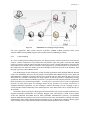
Architecture of an infrastructure mode WLAN ........................ 8
UMTS/WLAN loose coupling and tight coupling ................... 11
Horizontal handoff and vertical handoff ................................. 13
Test voltage in parallel circuit ................................................. 20
Generating packets using TCP-spray ....................................... 21
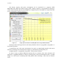
Laptop power information from BatteryMon when using the
WLAN interface....................................................................... 22
Laptop power information from BatteryMon when using 3G
interface ................................................................................... 23
USB packet types ..................................................................... 24
Three USB communication stages .......................................... 25
USB descriptors....................................................................... 26
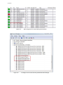
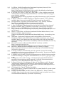
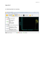
The beginning of USB enumeration ....................................... 27
The beginning of URB ............................................................. 27
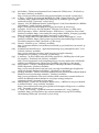
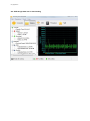
Detailed URB information ...................................................... 28
Device descriptor information ................................................ 29
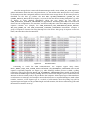
Mass storage device is removed during the enumeration ...... 30
The dongle is seen as three devices by the Windows device
manager ................................................................................... 30
New device starts ..................................................................... 31
Polling transaction .................................................................. 32
Connecting to the Internet ...................................................... 32
The last 21 packets watched by USBTrace .............................. 33
General PPP frame format ...................................................... 34
AT commands between laptop and dongle............................. 34
Two interfaces of USB dongle ................................................. 35
NDIS driver architecture ........................................................ 36
RNDIS architecture ..................................................................37
USB dongle architecture ..........................................................37
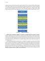
A simple workflow of USB dongle .......................................... 40
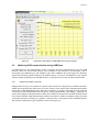
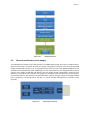
Main functions of configuration page...................................... 41
List of Tables | xi
List of Tables
Table 2-1:
Table 2-2:
Table 2-3:
Table 3-1:
Table 4-1:
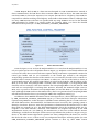
Examples of IEEE 802.11 standards [9][10] .............................7
3G/WLAN scenarios and their capabilities [14]......................10
Comparison between loose coupling and tight coupling ........ 16
Huawei E1550 USB dongle power consumption ..................... 21
Handoff policy parameters ..................................................... 40
List of Acronyms and Abbreviations | xiii
List of Acronyms and Abbreviations
1G
2G
3G
3GPP
4G
AAA
ACK
ACM
AP
CDC
CDMA2000
CH
CPU
CRC
CSCF
DECT
DHCP
DNS
DSL
EAP
ETSI
FCS
GGSN
GPS
GPRS
GSM
HDLC
HSS
HSPA
I-CSCF
ICT
IEEE
I/O
IMS
IoT
IP
IRP
IRQ
ISP
LAN
LTE
MDL
MDS
MIMO
NAK
NAT
First Generation
Second Generation
Third Generation
3rd Generation Partnership Project
Fourth Generation
Authentication, Authorization and Accounting
Acknowledgement
Abstract Control Model
Access Point
Communications Device Class
Code Division Multiple Access 2000
Correspondent Host
Central Processing Unit
Cyclic Redundancy Check
Call Session Control Function
Digital Enhanced Cordless Telecommunications
Dynamic Host Configuration Protocol
Domain Name System
Digital Subscriber Line
Extensible Authentication Protocol
European Telecommunications Standards Institute
Frame Check Sequence
Gateway GPRS Support Node
Global Positioning System
General Packet Radio Service
Global System for Mobile Communications
High-Level Data Link Control
Home Subscriber Server
High Speed Packet Access
Interrogating CSCF
Information and Communication Technologies
Institute of Electrical and Electronics Engineers
Input/Output
IP Multimedia Subsystem
Internet of Things
Internet Protocol
I/O Request Packet
Interrupt Request
Internet Service Provider
Local Area Network
Long Term Evolution
Memory Descriptor List
Multi-access Data Server
Multiple Input Multiple Output
Negative Acknowledgement
Network Address Translation
xiv| List of Acronyms and Abbreviations
NCM
OFDMA
OS
P-CSCF
PCMCIA
PCI
PDA
PID
PNP
PPP
QMI
QoS
RADIUS
RAN
RAS
RNC
RNDIS
S-CSCF
SGSN
SIM
SIP
SMS
SNR
STCP
TD-SCDMA
UE
UMTS
URB
USB
USB-IF
UTRAN
WCDMA
Wi-Fi
WLAN
Network Control Model
Orthogonal Frequency Division Multiple Access
Operating System
Proxy CSCF
Personal Computer Memory Card International Association
Peripheral Component Interconnect
Personal Digital Assistant
Packet ID
Plug and Play
Point to Point Protocol
Qualcomm MSM Interface
Quality of Service
Remote Authentication Dial in User Service
Radio Access Network
Remote Access Service
Radio Network Controller
Remote Network Driver Interface Specification
Serving CSCF
Serving GPRS Support Node
Subscriber Identification Module
Session Initiation Protocol
Short Message Service
Signal to Noise Ratio
Stream Transmission Control Protocol
Time Division Synchronous Code Division Multiple Access
User Equipment
Universal Mobile Telecommunications System
USB Request Block
Universal Serial Bus
USB Implementers Forum
UMTS Terrestrial Radio Access Network
Wideband Code Division Multiple Access
Wireless Fidelity
Wireless Local Area Network
Introduction | 1
1 Introduction
Information and communication technologies (ICT) have completely changed the world in a relatively
short period of time. Only two to three decades ago, the telegraph was still widely used for long
distance message transmission in many countries, and most people had never heard the word
“Internet”. Today the Internet has become an indispensable part of people’s lives throughout the
world. Instead of going to the post office to send a telegram, you can generally reach nearly anyone by
simply sending an email from any location that has Internet connectivity.
Another remarkable change brought about by ICT is the widespread popularity of mobile phones.
Today the number of mobile phone subscribers is much greater than the number of landline
subscribers. Many countries have a mobile phone penetration rate above 100%. For instance, Europe
has the highest mobile penetration rate in the world, with the total number of connections being 132%
of the population of Europe in 2012 [1].
With the increasing use of the Internet and mobile phones, there has been a spontaneous market
demand for convergence of these two technologies. Customers are not content to access the Internet
via a fixed desktop computer, but expect to surf and access the Internet wirelessly, from any location
that has network connectivity. This demand has stimulated the deployment of many types of wireless
networks. Two of the most prevalent types of wireless networks are the wireless local area network
(WLAN) and high speed wide area cellular networks (often called “mobile broadband”). Today the
most popular instance of the later type of network is the various types of third generation (3G) and
more recently fourth generation (4G) cellular networks. In this thesis, unless otherwise stated, we will
simply equate mobile broadband, with one specific type of 3G network: Universal Mobile
Telecommunications System (UMTS) - Wideband Code Division Multiple Access (WCDMA). We make
this simplification since this project started originally during 2009, during that time the most widespread type of 3G network was WCDMA and WCDMA offered the highest peak data rates of the
various 3G networks – thus with respect to our analysis it presented the strongest alternative to
WLAN. To be specific, we will focus on the cellular standards introduced by the 3rd Generation
Partnership Project (3GPP). By 2015 the new mobile network Long Term Evolution (LTE) has been
widely deployed in many countries. LTE uses a different wireless communication standard than
WCDMA; however, this thesis focuses on the communication interface with a laptop computer, rather
than external radio links, so our research did not shift to LTE. The conclusions should be valid for
both WCDMA and LTE radio interfaces. Therefore, throughout this thesis the term “mobile
broadband” simply refers to high speed wide area wireless access to the Internet.
1.1
Problem statement
Wireless Internet access has become very common in recent years, and there are many different
access solutions. People can connect their laptop to the Internet via a WLAN hotspot, through a
mobile phone, portable modem, or other similar device, implemented for example, as a 3G Universal
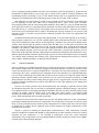
Serial Bus (USB) dongle. There are various USB dongles are available in the market and the market is
huge. Huawei, a Chinese telecommunications manufacturer, announced that the company shipped
more than 50 million mobile broadband units in 2012, including data cards, dongles, embedded
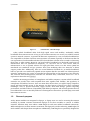
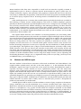
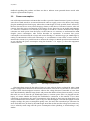
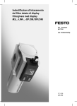
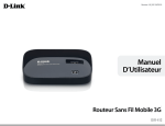
modules, etc. [2]. An example of such a USB dongle is shown in Figure 1-1.
2 | Introduction
Figure 1-1:
Huawei E1550 - a 3G USB dongle
Today mobile broadband offers both high speed access and mobility. Technically mobile
broadband allows Internet access as long as your mobile transceiver can access your cellular network
operator’s network. However, in practice the data rates experience by a user via mobile broadband are
not comparable to the data rates that users experience via WLAN, especially as the data rate that the
user experiences is both unstable and often lower than the data rate that users are used to when using
their home or office WLAN. Moreover, 3G based mobile broadband was developed based upon an
infrastructure that was optimized for telephony, i.e., the focus was on voice service. Such an
infrastructure is not an optimal solution for high speed data service. For this reason 3GPP has
introduced new standards and 3G operators have been modifying their core networks to better
support packet data. Additionally, there are several different standards for 3G mobile broadband,
hence to provide a user with locally optimal service requires that the user make use of heterogeneous
networks. Furthermore, the variety of networks has increased due to the emergence of 4G networks.
The research about heterogeneous networks has attracted many researchers, there are a lot of
explorations about this area [3][4][5].
With the increasing prevalence of smartphones and tablet computers, current mobile broadband
networks can provide users with acceptable data rates together with mobility. The popularity of
smartphones and tablets, however, does not mean these devices have yet replace laptop computers,
people still need wireless access to the Internet via their laptops. Laptops have many prominent
advantages, such as physical keyboards, bigger screens, more disk storage, greater computing
performance, and file & software compatibility with desktop computers. The research question that we
have addressed is: How to smoothly make use of heterogeneous networks to provide laptop users with
better Internet service?
1.2
Research purpose
Today, WLAN modules are integrated in laptops, so laptop users are used to accessing the Internet
wirelessly by WLAN. Common mainstream laptops do not have modules to connect to cellular
networks, therefore many users utilize a USB dongle for wide area mobile broadband connectivity.
While smartphones can share Internet connection with laptops by wireless tethering, USB dongles are
much smaller and cheaper than smartphones. Additionally, USB dongles are specifically designed for
Introduction | 3
providing network connectivity. A USB dongle which combines WLAN and cellular modules together
would give laptop users a lot of convenience. Users would not need to manually search for available
wireless connections and decide which network is better, they would simply plug such a dongle into
their laptop, and then the dongle would try to connect with the user’s preferred network (usually a
WLAN offering the best communication quality). If there are no accessible WLANs, then the dongle
would connect via a wide area cellular operator’s mobile broadband service; for example, via a 3G
network. Not only users, but mobile network operators would benefit from this combined dongle,
since they can use the WLAN network for mobile data offloading to ease the traffic burdens due to the
explosion growth of Internet data traffic via their cellular networks. Because the communication
modules are inside the USB dongles, rather than integrated with laptops or smartphones, it is much
easier to modify and upgrade to new dongles (to get access to new types of wireless networks), which
is good news for dongle producers.
The aim of the thesis is to explore how heterogeneous networks could be exploited to provide a
laptop user with locally optimal service, while hiding the complexity of this heterogeneous service.
The goal is to understand the implications of integrating multiple network interfaces into a single USB
dongle. Questions that this thesis should answer include:
1.
Is there a market for a dongle that contains some specific set of wireless interfaces?
2. What should be the communication interface between this dongle and the host operating
system?
3. What parameters might the user want to be able to configure using this interface to the
dongle?
4. What should be the future direction for development of 3G/4G dongles?
There are various research strategies and methods for ICT research topics. To apply the
appropriate research methods, we need explicitly aware of our research aim and questions, clearly
understand what type of information is helpful to answer the questions, and then select the methods
which can generate the requisite data. This thesis focuses on design research, literature studies, and
experimental tests as the main methods. Common methods for social research such as interviews and
questionnaires were not utilized as when the work started there were no dongles available that
provided heterogeneous wireless Internet connectivity and much of the technical community was
either focused on high speed cellular networks or LANs, thus there seemed to be little that could be
gained by asking people about a device that would exploit heterogeneous networks.
In the years that have passed since this project started there has been a growing interest in
heterogonous networks, especially for off-loading macro cellular networks. One of the main reasons to
complete this thesis project was the chance to revisit some of the design decisions and questions that
this thesis raised long ago and to see if the questions and answers have changed.
1.3
General background about wireless networks
Wireless communications technology is not new, Guglielmo Marconi developed the first wireless
telegraph system in 1896 [6]. Today consumer adoption of wireless technology is a major
telecommunications trend. Wireless communication technology is evolving rapidly and there are an
increasing number of wireless communication applications in use every day. Examples of this
technology include broadcast radio and television, various satellite navigation systems (such as GPS),
WLANs, cordless & mobile telephones, and the explosion in the use of tablets and smartphones. In
this thesis we will focus on two of these technologies: WLANs and the wide area cellular networks that
have evolved to support mobile phones.
WLANs offer an efficient complement to wired LANs. Most WLANs use unlicensed radio
frequencies to transmit and receive data over the air. Some of the major reasons for the success of
WLAN have been that WLANs can easily be deployed, WLAN equipment is available at low cost, and
4 | Introduction
WLAN interfaces offer data rates comparable to wired local area networks. Typically a WLAN is
implemented as part of a home or corporate network. Some WLANs are open to public users, for
example in libraries, airports, and restaurants. The popularity of WLAN has led to more and more
users using it. Additionally, the popularity of WLANs has led to the incorporation of WLAN interfaces
in all current laptop computers and an increasing fraction of handheld devices (including mobile
phones).
Today mobile phones are so common that a mobile phone is probably the first device you think of
when hearing of wireless services. Mobile telephony (also known as cellular telephony) operators
generally use licensed spectrum to provide telephone services over a contiguous area, normally a large
area covered by numerous cells. Cellular technology is the underlying technology for these wide area
mobile wireless communication systems. Each cell provides wireless connectivity for a given area,
while the mobile network’s core infrastructure provides the required functions to enable a user to be
authenticated, to be reachable despite the terminal move from one cell to another, and to provide
connectivity to devices within a cell.
The original cellular networks, now referred to as the first-generation (1G), used analog traffic
channels. The second-generation (2G) networks were based on digital technologies. These 2G devices
were introduced into the telecommunication market in the 1990s. The 2G vendors and operators had
great success and 2G technologies are still used today (although in a number of countries these
devices are being phased out, and many operators are planning to terminate 2G service). Voice
telephony was the main focus of 1G and 2G mobile phone services; however, data services have
become increasingly important in recent years, especially after the introduction of third-generation
(3G) technologies. The high data rates (7 Mbps in the downlink direction and nearly 1 Mbps in the
uplink direction in the first 3G devices and networks) made mobile web browsing smooth and
convenient. The wide deployment of fourth-generation (4G) cellular networks further promotes this
trend. In addition to web browsing, an ever-increasing variety of Internet based services are becoming
available via mobile broadband. These services range from simple services (such as uploading and
downloading documents, images, etc.) to augmented reality (such as Layar (http://www.layar.com)
and Wikitude (http://www.wikitude.org/)).
1.4
Modems and USB dongles
The term “modem” is derived from a contraction of the words “modulation” and “demodulation”. The
original modems worked exactly and only as the name implies, i.e., at the transmitter the device
modulated a signal based upon an input and at the receiver the device demodulated the signal to
reproduce the input. Current modems are more sophisticated products and offer many extra
functions, such as integrated routers and firewalls. The point-to-point protocol (PPP) is widely used
together with modems and simple links in order to transport data between two peers. PPP is a full
duplex, bit oriented protocol that can run over synchronous or asynchronous links [7]. PPP was not
specifically designed for any particular type of higher layer protocols. PPP supports data transfers over
many types of physical media, including (but not limited to) serial & parallel twisted pair links and
cellular networks. In practice, PPP is widely used as a data link layer protocol to encapsulate IP
packets for transmission over modem links
A mobile phone could be used as a wireless modem to connect a laptop computer to the Internet.
Using a USB cable was once the mainstream way to connect a mobile phone and a laptop, but a
Bluetooth or infrared link could also be used (depending upon the phone). Nowadays connecting via
WLAN to a smartphone is very popular and this allows the computer connected via the WLAN
interface to utilize the wide area cellular connectivity of the smartphone. This sharing of wide area or
local area connectivity through one device is often referred to as “tethering” or “Internet Sharing”. If
the tethering is not done over WLAN, then generally the software of the laptop uses the mobile phone
as if it were a dialup modem. Hence the protocol used for this data communication is PPP.
Introduction | 5
Instead of connecting the laptop with a mobile phone, several types of wireless modem cards can
be directly inserted into the computer. Traditionally many of these devices used the Personal
Computer Memory Card International Association (PCMCIA) card format or the later ExpressCard
format. The early designs of these devices were made to look like a dialup modem to the computer;
hence the data communications protocol used was PPP. While this may have been convenient from
the point of view of being able to utilize the modem software built into many operating systems;
unfortunately, this approach lead to the software treating this link as it would a dial-up modem; hence
the behavior is to connect and then remain continuously connected until the connection is explicitly
terminated. This has a number of undesirable effects, including unnecessary power consumption
when there is not continuous user traffic and vendors & network operators thought in terms of
“connected” services, hence delaying the transition to packet-based services.
Current laptop computers have one or more universal serial bus (USB) interfaces. USB version 2.0
offers a maximum data rate of 480 Mbps and compatibility with many products. The latest USB 3.1
(also known as SuperSpeed+ USB) increases the maximum data rate to 10 Gbps. Today the USB
interface has even replaced the traditional RS-232 serial interface, PS2 keyboard port, and PS2 mouse
port on most desktop computers. Because of the USB Forum’s efforts to foster the standardization and
interoperability of USB devices, a very wide range of devices exist with USB interfaces. Among these
devices are flash drives, modems, and Ethernet interfaces.
A USB wireless adapter is often called dongle, although this term was originally used for devices
that were used by applications to check that an application should be able to run on this computer. In
this earlier usage the “dongle” acted like a hardware key that was required in order to run the
application. However, according to BCE Inc. the word dongle is now widely used to refer to a
broadband wireless adapter [8].
There are 3G/4G USB dongles in various sizes and shapes. Most look similar to USB flash drives
(with various types of antennas attached to them). These dongles can indeed be used as flash drives or
memory stick, since there are flash memories present in these dongles. This flash memory contains a
file system with software which the host computers can load and run. This software frequently
includes a driver for one or more operating systems (OSs) and a management application so that the
user can control the dongle. However, this flash memory could be used to provide other software – for
example the software could provide routing software to route packets to WLAN or 3G interfaces. All
the necessary drivers and software are stored in the dongle by the manufacturer so that the user can
conveniently use the dongle immediately (or soon) after they plug the dongle into their laptop.
Each USB dongle contains a small modem and transceiver inside the dongle, enabling the device
to connect to a 3G/4G network. To access the Internet via a cellular network the OS frequently makes
use of the dongle as a modem to connect to a terminal server via PPP. The OS begins by negotiating
the protocol family it is going to use, gets assigned an IP address, and then the OS encapsulates IP
packets into PPP frames and transmits these frames over the PPP link to their destination. If the
connection is lost, then the process has to start all over again. This is the approach used by many
current dongles, but in this thesis a new approach is proposed.
This thesis proposes that a dongle should look like a WLAN or Ethernet interface (rather than a
modem). The device would simply send and receive link frames which encapsulate IP packets. This
network interface could make better use of the underlying network’s packet capabilities by sending
individual packets without the overhead of initiating a PPP session. Such a network interface would
remove the need for the Internet service provider (ISP) to provide a PPP server. If the ISP has an IPv6
network, then the device simply needs to know the IPv6 prefix of the network and it could proceed to
send IPv6 packets (this leaves aside the question of how the device authenticates itself and how it
would be authorized to use the network – these questions are left as future work – see section 5.2).
6 | Introduction
1.5
Limitations
It is important to note that this project started in 2009, long before the introduction of 3GPP’s Long
Term Evolution (LTE) networks. This thesis will not consider the case of LTE networks; however the
use of such networks rather than or in addition to UMTS WCDMA networks is largely a matter of the
difference in the radio links and does not change the communication between the laptop computer
and an external radio communication module.
After this project was started the USB Implementers Forum (USB-IF) defined a number of USB
Communications Device Class (CDC) protocols to provide this virtual Ethernet functionality, such as
CDC ACM (Abstract Control Model). In addition, Microsoft defined their own Remote Network Driver
Interface Specification (RNDIS) to provide similar functionality for their Windows OS machines.
The start of this thesis also predates the standardization and introduction of USB CDC Network
Control Model (NCM). NCM in fact eliminates the need for the PPP encapsulation of IP packets, thus
showing that in fact the idea that was initially proposed in 2009 for this thesis project was a good idea.
1.6
Structure of thesis
This first chapter has introduced the general background and stated the problem that is the focus of
this thesis project. Chapter 2 will give more background about the different types of networks that will
be considered and how the user can make use of these heterogeneous networks. Chapter 3 describes
the research methods and details of applying this method to solve the problem. Chapter 4 describes
some technical parameters of the new designed dongle and business analysis for the market. Finally,
Chapter 5 summarizes the conclusions, suggests future work, and sets this thesis in the context of
economic, social, environmental, and ethical considerations relevant to this thesis project.
Background | 7
2 Background
There are several different wireless internet access technologies available for mobile users. Of these
the most common are WLAN and cellular networks. This chapter provides some background
information about these two types of access technologies, and then presents some of the methods that
can be used to couple them.
2.1
WLAN
The Institute of Electrical and Electronics Engineers (IEEE) has approved a set of standards for
WLANs: the IEEE 802.11 family. Table 2-1 shows some of the most frequently used IEEE 802.11
standards. Wireless Fidelity (Wi-Fi™) is a trademark of the Wi-Fi Alliance, and the label "Wi-Fi
Certified" on a product means that the product has been tested to comply with the indicated standard.
However, the term Wi-Fi is often misused by many writers as a synonym for IEEE 802.11 or another
type of WLAN.
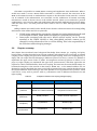
Table 2-1:
Examples of IEEE 802.11 standards [9][10]
Standard
Frequency
Data rates (max)
Max range (indoor)
802.11b
2.4 GHz
11 Mbps
38 meters
802.11a
5 GHz
54 Mbps
35 meters
802.11g
2.4 GHz
54 Mbps
38 meters
802.11n
2.4/5 GHz
600 Mbps
70 meters
802.11ac
5 GHz
1.7/3.5 Gbps
35 meters
WLANs have occupied an important place in the local area network (LAN) market during the past
twenty years. Today deploying a WLAN is a compulsory complement to traditional LANs in many
organizations. In some cases, businesses only deploy WLANs and only deploy wired LANs within their
data centers. WLANs offer an efficient solution for places that are not easily served by wired LANs.
The coverage area of a WLAN is often called a Wi-Fi hotspot, as Wi-Fi has become a de facto
synonym for WLAN and because the coverage area is often a location where there are likely to be
users. The use of the term hotspot is often used to emphasize the difference in expectation of coverage,
i.e., a WLAN is expected to provide only localized coverage, while a wide area cellular network is
expected to provide (nearly) ubiquitous coverage. Viewed another way, lack of WLAN coverage is
expected to be the norm; while lack of wide area cellular network coverage is expected to be an
exception. Interestingly in 2015, the lack of WLAN is increasingly exceptional and unexpected; while,
the lack of wide area cellular coverage indoors is becoming more common in Stockholm (due to the
high loss to the radio frequencies being used - caused by the energy efficient windows that are
increasingly installed in buildings).
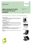
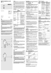
There are two operational modes defined in the IEEE 802.11 WLAN standards: infrastructure
mode and ad hoc mode. An access point (AP) is a vital component in an infrastructure mode network.
An AP acts as a bridge to allow WLAN interface equipped devices to connect to a backbone network
(see Figure 2-1). Note that this backbone network could be a wired or wireless network. In contrast in
an ad hoc network, an AP is not necessary as the devices communicate directly.
8 | Background
Figure 2-1:
Architecture of an infrastructure mode WLAN
IEEE working groups have developed a number of WLAN standards. The maximum theoretical
data rates of the commonly available IEEE 802.11 standards were shown in Table 2-1. Due to the high
data rates of WLAN, there is little difference for a typical user when surfing the Internet via WLAN or
LAN. Because of the very large numbers of devices made and the fact that the majority of the devices
are customer installed WLAN is relatively cheap and easy to deploy, hence it has become very popular.
However, WLAN does have an obvious flaw. As the name suggests, WLAN is a technology for local
access, which means that the wireless coverage area is not a very large area; hence as noted earlier
these coverage areas are often called “hotspots”. Because of this limited coverage, users can not count
on hotspots being everywhere nor are all hotspots open to the public.
Another problem of WLAN is caused by the frequency band(s) used by these devices. The popular
IEEE 802.11 b/g/n standards devices share the unlicensed 2.4 GHz radio frequency with many other
devices, e.g., Bluetooth, microwave ovens, cordless phones, etc., so there is a potential for conflict
when attempting to transmit as well as interference when multiple devices are operating in close
proximity. However, in Europe in practice most cordless phones are Digital Enhanced Cordless
Telecommunications (DECT) phones and hence use the 1.88-1.9 GHz band assigned to DECT and
most consumer microwave ovens are single frequency (hence represent only a narrow band interferer)
and are well shielded; thus the major interferer is Bluetooth – which hops all over the 2.4 GHz band –
thus generating the maximum interference, all be it in a narrow band at any given time hence for a
given IEEE 802.11 b/g/n channel this appears as short term interference.
2.2
Cellular networks
The term cellular refers to the fact that a geographical area is partitioned into a number of geographic
coverage areas, known as cells. Each cell contains a base station, which transmits signals to and
receives signals from, the mobile stations in its cell [11]. This approach is the basis of the cellular
network technology used by mobile phones today. Before the introduction of cellular networks, radio
telephone service was provided by powerful transmitters connected to a large antenna in order to
provide a long transmission radius – typically around 70-80 km [12]. Unfortunately, although the
area was large the system’s bandwidth was only sufficient to support about 25 channels at a time (with
one user per analog channel). This meant that only a few people could enjoy mobile phone service
Background | 9
within that huge area at any given time. In contrast modern cellular networks use numerous lower
power base stations, and divide the area into smaller cells, each cell is assigned a band of frequencies,
time slots, or codes (depending upon the particular system technology), so that thousands of users (or
more) can use their mobile phones at the same time.
With the widespread deployment of 3G and 4G, more and more people are using cellular networks
to access the Internet. There were three main types of 3G networks available when 3G were launched
into the market in the beginning of 21st century: Wideband Code Division Multiple Access (WCDMA),
Code Division Multiple Access 2000 (CDMA2000), and Time Division Synchronous Code Division
Multiple Access (TD-SCDMA). WCDMA had been deployed worldwide, while CDMA2000 is primarily
used in North America and South Korea, and TD-SCDMA is commercially available only in China.
Nowadays most WCDMA networks have been upgraded into High Speed Packet Access (HSPA) and
Evolved HSPA (also called HSPA+) which offer much higher data rates and significant improvement
in battery life. Since the second decade of this century, 4G networks are becoming globally deployed.
Several 4G candidate systems were developed, but now only two 4G standards are commercially in the
market: Mobile Worldwide Interoperability for Microwave Access (Mobile WiMAX) and Long Term
Evolution (LTE). Of these two, LTE is the current dominant 4G network worldwide. A distinct feature
of 4G is that it is not designed for the traditional circuit-switched telephony network, but rather it was
designed to support IP packet-switched services. 4G networks even use IP within their core networks,
hence these cellular + core networks are often called all-IP networks. The spread spectrum radio
technology used in 3G systems was abandoned in 4G and replaced by Orthogonal Frequency Division
Multiple Access (OFDMA) and other frequency domain equalization schemes. Combined with
Multiple Input Multiple Output (MIMO) technique, 4G networks can transfer much higher data rates
than its predecessor networks [13]. However, as we mentioned in the first chapter, the research in
thesis is based on 3G technology and the market penetration of 3G is still much bigger than 4G.
The biggest advantage of a wide area cellular network is the large coverage area. Users can access
the Internet anywhere as long as their device can transmit & receive a sufficiently strong signal.
However, the main disadvantages of these wide area cellular networks are their higher traffic charges
and comparatively lower data rates in comparison with WLAN, although data rates increased a lot
with the introduction of 3G/4G technologies. In some areas that are not yet covered by 3G/4G service
the user might only have access to a 2G service such as General Packet Radio Service (GPRS) or even
Global System for Mobile Communications (GSM) which offers much lower maximum data rates.
2.3
Coupling WLAN and 3G
3G networks provide what appears to the user to be “always on wide area internet connectivity”. While
these networks allow high mobility, their disadvantage is relatively low user data rates and high traffic
charges. While WLANs offer users much higher and more stable data rates, this is at the cost of low
mobility and limited geographic service areas. The advantages and disadvantages of 3G and WLAN
with respect to peak data rate make these two technologies complementary. Hence integration of 3G
and WLAN is a natural demand from the market. In response to this demand, more and more service
providers have started to offer such a service. Many proposals have been presented in the literature for
how to solve the many technical problems concerning the design and implementation of such a
heterogeneous network, such as how to do authentication, authorization, and accounting (AAA);
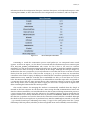
billing; support mobility; and provide quality of service (QoS) guarantees. The 3rd Generation
Partnership Project (3GPP) proposed in a preliminary feasibility study [14] six possible 3G/WLAN
integration scenarios based on the service experienced by the user. Each scenario extends the
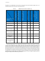
preceding one towards tighter integration. These six scenarios are show in Table 2-2.
In addition to combining WLAN and 3G service to achieve the best possible user throughput in a
given location, there are also many reasons for performing so-called vertical handovers between these
two technologies. An analysis of such vertical handovers to minimize battery power consumption is
10 | Background
described in [15]. Additionally, devices that are equipped with several interfaces might want to use
multiple interfaces at the same time, as described in [16].
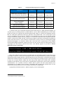
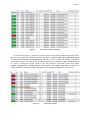
3G/WLAN scenarios and their capabilities [14]
X
X
X
X
X
Common customer care
X
X
X
X
X
X
3GPP system based
access control
X
X
X
X
X
3GPP system based
access charging
X
X
X
X
X
X
X
X
X
X
X
X
X
X
Access to 3GPP system
packet switched based
services from WLAN
Service continuity
Seamless service
continuity
Access to 3GPP system
circuit switched based
services with seamless
mobility
Scenario 6:
Scenario 5: Seamless services
Access to 3GPP system Circuit
Switched based Services
X
Scenario 4: Service continuity
Common billing
Scenario 2: 3GPP system based
Access Control and Charging
Service and operational
capabilities
Scenario 1: Common Billing and
Customer Care
Scenarios
Scenario 3: Access to 3GPP system
Packet Switched based services
Table 2-2:
X
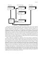
Generally speaking there are two different main approaches to design a heterogeneous 3G/WLAN
network: loose coupling and tight coupling. These two approaches were initially proposed by the
European Telecommunications Standards Institute (ETSI). We will discuss these methods in detail in
the following subsections. As mentioned in the beginning of the thesis, we choose UMTS WCDMA as
the target 3G network, since it was the most wide spread type of 3G network when this project started,
thus offering the most popular alternative to WLAN. Hereafter we will refer to this technology simply
as UMTS (since in the discussion of the different types of couplings it does not matter which of the 3G
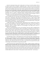
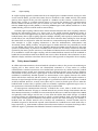
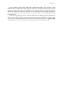
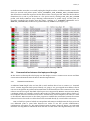
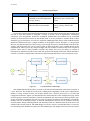
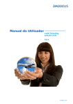
link technologies is used). Figure 2-2 shows the architectures of loose and tight coupling. Details of
the figure are explained in the following subsections.
Background | 11
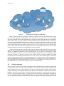
Figure 2-2:
UMTS/WLAN loose coupling and tight coupling
UE: User equipment; RNC: Radio network controller; UTRAN: UMTS terrestrial radio access
network, SGSN: Serving GPRS Support Node; GGSN: Gateway GPRS Support Node
2.3.1
Loose coupling
In a loose coupling interworking architecture, the WLAN gateway connects with the core IP network
without a direct connection to the UMTS network elements. The data paths of WLAN and UMTS
traffic are separate, and the interconnected networks are loosely coupled independent networks. The
data traffic from a mobile node in a WLAN to user equipment (a 3G terminal) does not go directly to
the UMTS network; rather the traffic passes first through an IP network (such as the Internet), then
through a gateway to the UMTS network.
The disadvantage of this architecture is that roaming agreements with multiple different WLANs
need to be established. However, the advantage is that WLAN and UMTS networks can be deployed
independently by different providers and the user can freely choose which network they wish to use
when both are available. Considering the large number of WLAN providers, establishing roaming
agreements between UMTS and WLAN operators is an expensive and complex problem (as generally
these agreements are bi-lateral agreements – so each pair of operators have to reach an agreement;
however, in some places there are exchanges where all the operators can connect and there is a
standard settlement agreement via the exchange). Another advantage of loose coupling is that it
avoids potential traffic bottlenecks in the UMTS network, since data traffic can be routed directly via
IP networks.
In literature about roaming in a heterogeneous infrastructure, the loosely coupled architecture is a
frequent researched architecture. For example, Ruggeri, Iera, and Polito [17] cited several similar
works and indicated that IEEE 802.1X, EAP (extensible authentication protocol), and RADIUS
(Remote Authentication Dial In User Service) can be used for AAA. An alternative offering non-binary
authentication using traffic shaping has been explored in [18]. In Raul Garcia’s Master’s thesis [19] he
shows mobility can be supported via Mobile IP and the Session Initiation Protocol (SIP).
12 | Background
2.3.2
Tight coupling
In a tight coupling approach a WLAN network is an integral part of a UMTS network, acting as a radio
access network (RAN), just like other RANs that are attached to that UMTS network. The WLAN
gateway must support all the protocols required in a UTRAN. In this scenario a mobile node in a
WLAN must connect to a UMTS network before it can access the Internet. The communications
between UMTS and WLAN occur just as between any other cells. The coupling could occur at the
Gateway GPRS Support Node (GGSN) or a Serving GPRS Support Node (SGSN). Mobile IP or other
UMTS mobility protocols could be used for interworking.
Normally tight coupling solutions have shorter handoff latencies than loose coupling solutions,
because the interworking occurs at a closer point to the mobile terminal. Simulation results of
real-time services and applications [20] show that loose coupling based on Mobile IP suffers longer
handoff latency than a tight coupling approach. Siddiqui, Zeadally, and Yaprak [21] indicate that the
overall delays (not only handoff latencies) are much lower when the data exchange is done through
the GGSN node as compared to when the networks are connected through the SGSN node. Another
clear strength of a tight coupling architecture is that the Authentication, Authorization and
Accounting (AAA), billing, mobility, and QoS support in UMTS networks can potentially be reused
over the WLAN cells; however, this is only feasible if WLAN and UMTS networks belong to the same
operator. Unfortunately, in practice it is unlikely that a mobile user can always connect via networks
operated by the same operator. Moreover, both UMTS and WLAN devices and configurations needed
to be modified to realize this tight coupling, and the UMTS backbone network must be modified to
handle the increased data traffic from WLAN APs. Due to these drawbacks, this architecture is more
difficult to deploy and fewer researchers have focused on this approach as compared to loose coupling.
2.4
Policy based handoff
In cellular telecommunications, the term handoff or handover refers to the process of transferring an
ongoing call or data session from one channel/link connected to a base station to another
(channel/link or another base station). As a fundamental operation for any cellular networks, handoff
management ensures mobile users maintain network connectivity despite users moving to different
cells. Details of this process have a great impact on how the old links are released and new links are
established. Traditionally handoff depends on measurements of the signals (between the mobile
device and the base station(s) and the reverse). For example, if the original link signal continues to
decrease in signal strength and the signal strength of a potential new link is increasing then a handoff
would be initiated. However, in many cases, there may be a need to decide upon when to make the
handoff based on other rules (or policies) such as a terminal’s capabilities, application types, costs, or
user preferences. This kind of handoff is called a policy based handoff.
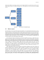
In heterogeneous UMTS/WLAN networks, a handoff also occurs when a mobile user roams
between different networks. A laptop in a UMTS network may want to change from UMTS to WLAN,
when WLAN connectivity is available, because normally the data rate in a WLAN is higher than UMTS
and generally traffic charges are flat rate or lower than the cellular data traffic charges. A handoff
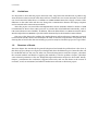
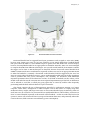
occurring between two dissimilar networks is called a vertical handoff, while a horizontal handoff
occurs when roaming between different cells/subnets that use the same technology, for instance, a
handoff from one cellular network cell to another cell. Furthermore, vertical handoff could be
classified as upward or downward. Upward vertical handoff is a handoff from a small sized cell to a
larger sized cell, e.g., from WLAN to UMTS, whereas downward refers to movement form larger cell to
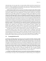
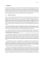
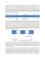
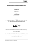
small cell. Figure 2-3 illustrates the difference between horizontal and vertical handoff.
Background | 13
Figure 2-3:
Horizontal handoff and vertical handoff
Horizontal handoff can be triggered based upon parameters such as signal to noise ratio (SNR),
bit error rates, frame error rates, etc. [22]. For example, we can simply define that a handoff should
take place when the SNR of a new WLAN hotspot is greater than the SNR of the current hotspot;
however, this simplified method is not appropriate for dissimilar networks, since it is not meaningful
to compare the SNR from different technologies. For upward vertical handoff, from WLAN to UMTS,
the trigger can be when no WLAN hotspots are detected, whereas downward vertical handoff from
UMTS to WLAN needs more considerations (especially as there may not be an appropriate WLAN AP
to make the handoff to). Certainly a downward vertical handoff could be triggered by the user, but
since our aim is reduce the burden on users, a more sophisticated handoff policy involving parameters
such as potential data rate, power consumption, cost, reliability, etc. should be used. Additional
important parameters that can be taken into account, for all kind of handoffs, are the velocity of the
mobile node and what are the current & near term expected requirements upon the link. A dwell timer
can be utilized to avoid the so called ping pong effect that is caused by mobile nodes frequently
performing handoffs back and forth between a pair of networks.
This thesis concerns the use of heterogeneous networks by applications running on a laptop
computer, rather than a smartphone or tablet computer. Due to the nature of a laptop (large size,
moderate to heavy weight, and large screen size) we can assume that the laptop is stationary when it is
used, hence we do not need to be concerned about rapid handoff due to node mobility, and hence we
focus on vertical handoff, especially on downward vertical handoff – as this can reduce the load on the
operator’s macro cell, increase the user’s average and maximum data rates, and potentially reduce the
costs for the user (both economic cost and battery power consumption).
14 | Background
2.5
Related work
Coupling 3G and WLAN networks has attracted a lot of interest from researchers, leading to many
different proposals. This section presents some of this related work, both proposals in academic
literature as well as industrial examples.
2.5.1
Policy based loose coupling framework
There already exists extensive literature concerning proposed 3G and WLAN coupling architectures,
especially those proposing loosely coupling. The common feature for all the proposed architectures
using loose coupling is the use of Mobile IP as the basic instrument of inter-system mobility and the
high level perspective of the integration process [23]. Another important focus is policy based handoff.
Since in practice a handoff decision is not only based on signal strength, but might depend on many
parameters, thus policy based handoff is a common solution. An example of a loose coupling policy
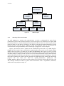
based handoff framework, proposal by S. Balasubramaniam and J. Indulska [24], is presented below.
This proposed framework categorizes policy parameters as “static context” or “dynamic context”.
Static contexts refer to parameters that do not change very often, such as the devices, networks, and
their QoS requirements; while dynamic contexts include current information about users and
networks, that change dynamically when user location or network conditions change. These contexts
are gathered in a "Context Repository" which is one of two crucial functional modules in their
framework. The other module is an "Adaptability Manager" which decides how to adapt to context
changes and when to execute a handoff. This manager is divided into two different processes: vertical
handoff decision and QoS mapping. Heterogeneous networks within a domain are formed as a domain
network cluster, with each cluster supported by its own adaptability manager and context repository.
There is also a proxy in each network which receives notifications about requested handoff operations
from the adaptability manager and redirects communication streams between different domains, such
as a correspondent host (CH) domain and a network domain.
A characteristic of this proxy is that it bi-casts the communication stream during handoffs (i.e.,
the proxy delivers two streams). A mobile host’s traffic follows a route from network 1 to network 2
and then on to a UMTS network. Initially a communication stream is transmitted through the proxies
in CH and network 1 to the mobile host. When a handoff is triggered, the stream is not only forwarded
to the mobile host but a copy is also forwarded to the new proxy in the network that the mobile host is
moving into. The bi-casting operation is terminated as soon as the redirected packets begin to arrive.
Bi-casting minimizes QoS violations during handoff, in terms of exceeding bounds on delay, jitter, or
packet loss.
This proposal also includes a detailed handoff decision algorithm. Their experiments with a
prototype showed that smart decision mechanisms are necessary for smooth adaptation of the
communication streams under different conditions.
2.5.2
An IMS-SIP based coupling framework
In tight coupling architectures, a WLAN is directly attached to a UMTS component (such as the GGSN
or SGSN). A clear advantage is the possibility to reuse the UMTS mobility management techniques.
However, tight coupling is difficult to implement in networks belonging to different operators, and
less literature exists about this approach than for loose coupling. Rather than using Mobile-IP, some
frameworks based on the IP Multimedia Subsystem (IMS) and Session Initiation Protocol (SIP) have
been proposed for tight coupling. Before presenting this type of framework, we give a brief overview of
IMS and SIP.
IMS is based upon internet protocols. IMS is a network architecture aiming to merge Internet and
cellular worlds by providing a horizontal control layer that isolates the access network from the service
layer. It is seen as a promising solution for facilitating multimedia service creation and deployment, as
Background | 15
well as supporting interoperability and network convergence. IMS was specified by 3GPP and was
introduced in UMTS releases 5 and 6 [25]. SIP is widely used in IMS for creating, modifying, and
terminating sessions consisting of one or more media streams. SIP is an application layer protocol
designed to be independent of the underlying transport layer (such as TCP, UDP, or STCP).
The Call Session Control Function (CSCF) is a key element in IMS as it processes control messages
and all signaling via SIP. The CSCF can be categorized into 3 parts: Proxy CSCF (P-CSCF),
Interrogating CSCF (I-CSCF), and Serving CSCF (S-CSCF). The P-CSCF is a proxy for all SIP messages
from end points to the rest of the IMS network. Normally it resides in the subscriber’s home network,
but could also be in a visited network. The I-CSCF acts as an entrance from a P-CSCF to an S-CSCF,
and it acts a Home Subscriber Server (HSS) to determine the relevant S-CSCF once it receives a SIP
message. Finally an S-CSCF is the node that eventually performs the actual user registration and
session control.
An IMS-SIP based framework proposed by Munasinghe, et al. [26]. Although this is not strictly a
tight coupling architecture; it is a closely coupled framework. In this framework, there are two initial
steps before establishing a SIP session. In the beginning, a MH does not know the IP address of the
P-CSCF. After learning the IP address of the P-CSCF the MH acts as a SIP client and sends a SIP
registration message through the P-CSCF to the S-CSCF and HSS. After registration the MH can
establish or be invited to a SIP session. In an MH originated session, the session data flow is initiated
by a SIP INVITE message sent from the MH, and is followed by several SIP messages such as
Provisional ACK, UPDATE, and ACK. Although the transmission mechanism in this framework is very
different from the Mobile-IP based approach used in previous section, the handoff solution is logically
very similar. Their framework also utilizes policy based decision making and introduces a network
entity called a "Mobility Manager" to manage vertical handoff.
2.5.3
Industrial proposals
Devices combining 3G and WLAN interfaces are available in the market, for instance, as incorporated
into wireless routers and some netbooks. Plugging a 3G USB dongle into a pocket size wireless router
such as the Huawei D100 or Option Globesurfer X.1, customers can access the Internet by wirelessly
connecting to the router. A similar product originally from Novatel Wireless, Inc. called the MiFi does
not even need a USB dongle; this credit card size device can be turned into a hotspot by simply insert a
Subscriber Identity Module (SIM) card. Netbooks can also access the Internet via built-in 3G and
WLAN modules, but they lost the market after the great success of Apple’s iPad, and since 2011 many
personal computer manufacturers produce Chromebooks for the same segment of the market that
netbooks serviced.
However, all of above products have obvious drawbacks. For example, a netbook can access both
3G and WLAN networks, but it is not able to automatically perform a handoff between a 3G network
and a WLAN. If there is a new high speed WLAN available, then the user must manually switch to this
network. As regards wireless routers, such as the MiFi, they simply utilize a 3G network while
providing the functionality of a local WLAN AP. In addition, many wireless routers need external
power, which substantially decreases their portability.
Customers need products that exploit both 3G/4G and WLAN interfaces, while automatically
performing handoffs between these two technologies. For vendors this is fortunate, because it means
there is a great potential market, therefore many companies are working in this area, and each hopes
to design such a coupling device, although some of these designs may require modifications to the
infrastructure networks.
Alcatel a proposed aWLAN/3G interworking architecture [27]. This architecture provides
extensive integration of UMTS and WLAN by using Mobile IP. It offers seamless connectivity without
requiring any user interaction, i.e., the coupling is transparent to the user. Some important
components of this architecture are an Intelligent GGSN (I-GGSN), multi-access data server (MDS),
and real-time content charging manager.
16 | Background
The MDS is responsible for UMTS/WLAN roaming and implements AAA mechanisms. When a
mobile user needs to access a WLAN while connected to a cellular network, the AAA server in the
MDS of the WLAN forwards an authentication request to the subscriber’s home network. A session
can be initiated if the authentication was successful. In this architecture all WLAN accounting
information is stored in the AAA server of the cellular network. There are two methods to perform
authentication. One reuses the SIM card mechanisms and Extensible Authentication Protocol (EAP);
while the other uses a one-time password which could be sent as a Short Message Service (SMS)
message.
Billing in WLAN is normally hard to handle, hence Alcatel’s architecture reuses the existing billing
mechanisms of the cellular network. In particular:
•
•
2.6
WLAN access network APs generate the relevant accounting information and send
it to the MDS of UMTS, which makes it available for postpaid bill processing.
Data traffic associated with the user’s WLAN session activity can be securely
tunneled to the UMTS I-GGSN so that value-added real-time content can be
charged for using enhanced on-line or off-line billing. This is the responsibility of
the real-time content charging manager.
Chapter summary
This chapter first introduced some background knowledge about WLAN, 3G, coupling, and policy
based routing, and then described some relevant academic and industrial work concerning 3G/WLAN
coupling. Loose coupling was given more attention than tight coupling, since loose coupling is easy to
deploy and can couple networks belonging to different operators. However, it seems very difficult to
implement the upper service levels of 3GPP’s six integration scenarios [17](shown in Table 2-2 on
page 10). Tight coupling can implement the upper level 3GPP scenarios, and these approaches are
expected to offer low handoff latency than loose coupling, but must face the serious disadvantage of a
bottleneck arising due to the amount of data from/to WLAN APs – as the UMTS backbone was not
designed to support these high data rates nor the high aggregated data rates. Another drawback is that
the coupled networks need to belong to the same operator or have agreements with operators, which
could not be a easy work in practice. Table 2-3 summarizes some of differences between loose and
tight coupling.
Table 2-3:
Comparison between loose coupling and tight coupling
Loose coupling
Tight coupling
Data bottleneck
No
Yes
Deployment
problems
Common AAA solution,
Mobile IP in UMTS and WLAN
Modifications on UMTS/WLAN
components and terminals
Deployment
preference
WLAN providers
Cellular network operators
Deployment
complexity
Low/Medium
Medium/High
Handoff
performance
Low/Medium
Medium/High
Background | 17
Loose coupling normally utilizes Mobile IP for handoff management. This approach is most
suitable for the 3G USB modems which using PPP connections. Many tight coupling solutions employ
IMS and SIP. These solutions are well adapted to services which are not based on PPP. Although tight
coupling is currently more difficult to implement, many researchers believe that tight integration is
the next logical step toward the implementation of seamless handoff in an integrated WLAN/UMTS
environment [25].
From a user’s perspective, however, it does not matter how the underlying UMTS and WLAN are
utilized, because the user simply wants a device that utilizes some mechanism to choose the right
wireless network automatically and transparently. This suggests that the solution is policy based
and need not be coupled to the specific types of underlying networks that might be utilized.
Method | 19
3 Method
The purpose of this chapter is to describe the research methods used in this thesis and what we have
done based on the methods. First we provide an overview of the research methods and research
process in section 3.1. Section 3.2 focuses the power consumption test for USB dongle. Section 3.3
describes the USB communication between the dongle and laptop, and demonstrates the whole
Internet connection process by using a USB dongle. Section 3.4 introduces two communication
interfaces between dongle and laptop and compares the differences. Finally, based on results from
research methods, section 3.5 shows the general architecture for our designed dongle.
3.1
Research method
How to select the appropriate scientific method is an issue that we must take into account in the
beginning of each research project. There are a number of well-established research strategies and
methods, such as survey, experiment, case study, observation study, etc. However, there is no
standard solution which is good for all research; therefore, researchers should deliberately choose
suitable research methods for each research project. Researchers must be explicitly aware of the
questions they are going to figure out, and know what type of information is required to answer the
questions, and then select the methods that can produce the required information and data. So we
need to carefully consider the research questions before we can choose suitable methods for this thesis
project.
The aim of the thesis is to explore how heterogeneous networks could be exploited to provide a
laptop user with locally optimal service, while hiding the complexity of this heterogeneous service.
The goal is to understand the implications of integrating multiple network interfaces into a single USB
dongle. Section 1.2 (on page 2) listed some of the questions that this thesis should answer.
To answer these questions, we need to know related background information, the features of a
traditional USB dongle, what interface is used by the dongle, and how the dongle works. Then based
on this information, we propose an improved solution for a USB dongle and analyze the advantages
and market prospects of this new dongle.
The first method we applied was a literature study - a special kind of observational study where
related documents and information are checked. By using this method we found both academia and
industry have fully understood the market requirement for coupling cellular networks and WLAN, and
realized the traditional USB dongle's deficiency is working as a dial up modem. These publications
and products are also evidence to show that our research is not simply exploring a scientific question
for our own personal interests, but rather a development driven by many researchers and by market
needs.
To comprehend the operation of a USB dongle, an experimental method has been adopted as the
research method. Since power is a significant issue for mobile device, we compared the power
consumption of a USB dongle for WLAN and for a 3G network, to demonstrate if whether using the
cellular network consumes more power than when using a WLAN (see Section 3.2). To thoroughly
understand the communications between USB dongle and laptop computer, we monitored the whole
Internet connection process when using a USB dongle (see Sections 3.3 and 3.4).
Based on our literature study and experimental tests, after careful analysis and extensive search
on the Internet, we select RNDIS as the interface between USB dongle and laptop. To evaluate the
market acceptance for a product, typically questionnaire or interviews are applied as the research
method. Due to various containts these methods were not employed. However, since the time that this
project began in 2009 several vendors have produced products similar to what was proposed in 2009,
we can use information about these products to evaluate our earlier design decisions and conclusions.
Therefore, we reviewed the market in recent years in order to extract information from customers’
20 | Method
feedback regarding this product and then use this to indicate some potential future trends. This
analysis is presented in Chapter 4.
3.2
Power consumption
One of the important features of USB is that it is able to provide a limited amount of power to a device.
Users do not need search for an external electrical outlet to supply power to the device; they simply
plug the USB dongle into their laptop. This makes a USB dongle an easily portable device. Moreover,
the user does not have to worry about charging a battery in the device. Customers, however, often are
concern about the power consumption of the laptop’s power when they are in mobile environment,
i.e., without a connection to an external power supply. It would be a serious drawback if the dongle
consumes too much power from the laptop via the USB. So it is necessary to understand the USB
dongle’s power consumption. This section describes an experiment to measure this power
consumption. We measured the voltage and current flowing to a Huawei E1550 3G USB dongle by
cutting a USB extension cable and connecting it to a multimeter to form either a series circuit to
measure the current (I) or parallel circuit to measure the voltage (V). Based upon these measurements
we can calculate the power consumption using the formula P = VI. Figure 3-1 shows the equipment
used for this test.
Figure 3-1:
Test voltage in parallel circuit
The USB voltage output by the author's laptop is 5.08V when no device is plugged in. After a USB
dongle is plugged and connected to the Internet, the current varies from 0.05 A to 0.27 A. The current
is higher when data throughput increases, whereas the voltage decreases somewhat at lower data
rates. We identified 5 different usage phases and present the details of these phases in Table 3-1. From
this table, we can see that the 3G USB dongle starts to consume power after it is plugged into the
laptop, no matter whether the dongle has established a connection to the Internet or not. After
connecting to the Internet, the power consumption of the dongle is about 0.65 W when there is no
active communication and around 0.75 W at very low data throughput. Once the throughput exceeds
roughly 10 Kbps, the power consumption quickly rises; the more data transferred per unit time the
more work that has to be done by the USB dongle. Note that in this state the voltage and current vary
over a relatively small range and the power consumption when uploading or downloading is very
similar.
Method | 21
Table 3-1:
Huawei E1550 USB dongle power consumption
Usage Phase
Voltage (V)
Current (A)
Power (W)
USB dongle connected to laptop,
but not connected to the Internet
4.86-4.87
0.05-0.06
0.2435-0.2916
Connected to the Internet, but no
active data communication
4.57-4.58
0.14-0.15
0.6412-0.6855
Very low throughput
(below 10Kbps)
4.50-4.51
0.16-0.17
High upload throughput
4.22-4.23
0.25-0.26
1.0575-1.0972
High download throughput
4.20-4.23
0.25-0.27
1.0575-1.134
0.7216-0.765
To measure the power consumed during the period when there is a high upload throughput, we
use TCP-spray as a packet generator to send packets to a server. When using TCP-spray we can set the
packet size and rate to generate the desired upload traffic. Figure 3-2 shows the command used for
this test. With these parameters TCP-spray generates 1000 packets with a size of 2048 bytes to the
server at IP address 130.237.209.214. A total of 2,050,048 bytes are sent in 53.961 seconds, and the
average transmission speed is about 37 kbytes/s. It should be noted that this command sends the
traffic to a TCP service called “discard” on the target computer, thus before running this command we
need to turn this service on, since usually it is turned off for security reasons. For testing during high
download throughput, we viewed an online video, since this load is representative of the highest
download throughput application used by most users. We can see from the test results that the power
consumption for this service could be more than 1.1W. Related graphs are provided in Error!
Reference source not found..
Figure 3-2:
Generating packets using TCP-spray
These tests utilized a Huawei E1550 3G USB dongle. An interesting question is how this power
consumption compares to the power consumption when accessing the Internet by WLAN. One might
assume that using a WLAN interface * should require less power than using a 3G interface because the
cellular base stations are likely to be further away and it requires more energy to move a given amount
of data over a longer distance within the same time period. Based upon mobile users’ feedback
available on the Internet, most users feel 3G communication requires more power than comparable
communication over a WLAN. However, Andrew Baxter reports that the actual WLAN power
consumption is very similar to the 3G power consumption [28]. By using the formula below, we can
calculate the battery lifetime in hours of a laptop with/without a USB dongle.
Laptop Battery lifetime in Hours = Battery Capacity / Power Consumption
*
More specifically a IEEE 802.11g interface was used.
22 | Method
The battery capacity and power consumption can be measured by a program called
BatteryMon [29]. When the author's laptop (with a battery capacity of 40759 mWh) is playing an
online video by WLAN and the screen brightness is high the power consumption is 20304 mW. This
power consumption is shown in Figure 3-3.
Figure 3-3:
Laptop power information from BatteryMon when using the WLAN interface
Based upon the formula given above, the battery lifetime in hours is 40759mWh / 20304mW = 2
hours and 0.5 minute.
I repeated the test in the same environment, but used a 3G USB dongle instead of the Wi-Fi
interface. According to the results shown in Figure 3-4, the battery operating with 3G is:
3G Battery Hours = 40759mWh / 20347mW = 2 hours and 0.2 minute
So there is only 0.3 minute difference between the two scenarios, thus most customers will
experience a negligible difference in battery operating times. This test demonstrates that a 3G USB
dongle is no more power consuming than using WLAN when streaming a video from an internet
server.
Method | 23
Figure 3-4:
3.3
Laptop power information from BatteryMon when using 3G interface
Watching USB communication using USBTrace
To understand how the USB interface works, we analyze the data communication across the USB
interface. There are several USB analysis tools available on the Internet for downloading, such as
SnoopyPro [30], SniffUSB [31], and USBTrace [32]. Since USBTrace has good support for Windows
system, the operating system running on the author's laptop, I choose to use USBTrace as the analysis
software. Before using this powerful USB analyzer, we first give an overview of USB communication.
3.3.1
USB communication overview
USB provides an easy-to-use solution to connect various devices to computers by a standard interface.
USB is host controlled, thus there has to be a host acting as a bus master. The communication utilizes
token, data, and handshaking frames (here after referred to as packets). The USB protocol stack has
several layers. The maximum data rate of USB 2.0 * (in high speed mode) is 480 Mbps, 1.5 Mbps in low
speed, and 12 Mbps in full speed mode. Unlike other similar serial interfaces in which the data format
is not clearly defined, USB communication utilizes transactions, similar to Ethernet frames, but with
each USB transaction consisting of 3 packets: a token packet, a data packet, and a handshake packet.
The formats of these three types of packets are shown in Figure 3-5.
*
USB 3.0 was not defined at the time that this project started; hence this thesis will not consider USB 3.0.
24 | Method
Token packet
Sync
PID
ADDR
ENDP
CRC5
EOP
8/32 bits
8 bits
7bits
4bits
5bits
n/a
Data packet
Sync
PID
Data
CRC16
EOP
8/32 bits
8 bits
0-1024 bytes
16bits
n/a
Handshake packet
Sync
PID
EOP
8/32 bits
8 bits
n/a
Figure 3-5:
USB packet types
“n/a” in this figure means not applicable
All USB packets start with a synchronization (sync) field. This field is used for synchronization of
the clock in the receiver with the clock in the transmitter, and it is 8 bits long in both low & full speed
and 32 bits long in high speed mode. The next field is a Packet ID (PID). This ID indicates the type of
the packet. The cyclic redundancy check (CRC) field is 5 bits long in a token packet and 16 bits in a
data packet. The last field of every packet is End-of-Packet (EOP). This field terminates the packet.
The token packet specifies which device and endpoint the packet is to be sent to. Thus there is an
address (ADDR) and an endpoint (ENDP) field in the token packet. A USB host can support at most
127 devices, since the ADDR field has 7 bits, and address 0 is not valid.
There are three different handshake packets: ACK which acknowledges to the sender that a packet
has been successfully received; NAK which indicates that the packet could temporarily not be sent or
received; and STALL which indicates that the endpoint halted or a control request is not supported.
All of these handshake types are distinguished based upon their PID values.
These three different packets (token, data, and handshake) comprise a USB transaction. A
complete USB communication procedure consists of numerous such transactions. The procedure can
be divided into three stages: setup stage, data transfer stage, and status stage. Figure 3-6 illustrates
these three stages. Note that during the data transfer stage, the data is separated into the fixed sized
payloads, except for the last one.
Method | 25
Setup stage
Data transfer stage
Status stage
Token packet
Token packet
Token packet
Data packet
Data packet
Data packet
Token packet
Data packet
Token packet
USB host
Data packet
Figure 3-6:
Three USB communication stages
Under Microsoft’s Windows operating system, Plug and Play (PnP) (a type of hot swapping)
enables adding or removing peripheral components without shutting down the host system. PnP is an
important characteristic of USB. The PnP manager, a subsystem of Microsoft’s Windows I/O
manager, provides the PnP functionality. As PnP technology is implemented for USB, the host OS
automatically configures each device after it is added. Note that the USB host controls all the
communications, so there is no need for each external device to be allocated an Interrupt Request
(IRQ) vector slot or I/O addresses. However, the USB bus controller inside the computer does have an
assigned IRQ and an address on the PCI bus which is used for communication between the CPU and
all devices on the USB. As a result, all of the devices attached to a single USB host interface share a
single interrupt and a single I/O address [33]. To recognize different USB devices sharing the same
interface, USB uses a technique called enumeration to find all of the devices, and then the operating
system associates each device with a device descriptor.
When a USB device is plugged into a USB host, the host will perform an enumeration to
determine all of the devices attached to this USB controller. The host will recognize the presence of the
device and assign it a unique 7 bit device address. After assigning each of the devices an address, the
host queries each device for its descriptors. These descriptors contain information about each specific
device. USB devices have a hierarchy of descriptors. These descriptors are shown in Figure 3-7. Each
USB device can only have one device descriptor, but can have more than one configuration descriptor.
Most devices, however, only have one configuration descriptor since changing the configuration
requires all activity on each endpoint to stop [34], thus it is inconvenient to do so in practice. A single
configuration can have many interfaces, and each interface looks like a group of endpoints that
accomplish a single function of a composite USB device. All communication between the USB host
and a USB device is addressed to a specific endpoint of the device (keeping in mind that a given device
can implement multiple endpoints). The endpoint can be a source of data (or the sink for data output
by the USB host). All data is transferred through a virtual serial pipe between the host and this
endpoint. There are four transfer types for endpoints: control, interrupt, isochronous, and bulk. For a
USB dongle, the data is transferred using a bulk transfer.
26 | Method
Device descriptor
Configuration
descriptor
Configuration
descriptor
Interface
descriptor
Endpoint
descriptor
Interface
descriptor
Endpoint
descriptor
Figure 3-7:
3.3.2
Endpoint
descriptor
Endpoint
descriptor
USB descriptors
Watching USB communication
We used USBTrace to monitor the communication in order to understand the entire device
enumeration process. Other software analyzers, such as SnoopyPro, use a filter driver to capture USB
bus activity; however, a serious limitation when using such a driver is that we cannot log any activity
until the driver for the device is loaded, so this driver would miss the USB enumeration process
between the host and the device. USBTrace avoids this limitation, thus we can monitor the
communication starting immediately after a USB dongle is plugged into a host computer.
Figure 3-8 shows the first 21 requests in the enumeration process after a 3G USB dongle is
plugged into the author's laptop. The packets supporting the PnP process are I/O request packets
(IRPs). The first request is an IRP_MN_QUERY_CAPABILITIES. This request is sent by the PnP
manager to learn the capabilities of a device, such as whether the device can be locked or ejected. The
first time stamp is 7.782311 second, but this is not when the enumeration began, rather the timer
started when the user clicks the “Start Monitor” icon in the graphical interface of USBTrace. Thus this
time stamp indicates how quickly the user plugged in the USB device after starting the monitoring
program. The next three PnP IRPs are QUERY_INTERFACE, QUERY_ID, and
QUERY_DEVICE_TEXT. All of these are minor functions to the major function IRP_MJ_PNP. The
PnP manager sends these IRPs to gather device information such as Capabilities, UINumber,
HardwareID, LogConf\BootConfig, etc.
Method | 27
Figure 3-8:
The beginning of USB enumeration
As we can see in Figure 3-9 the PnP process continues until packet 44. The PnP manager learns
the resource requirements and filters for these resources by QUERY_RESOURCE_REQUIREMENTS
and FILTER_RESOURCE_REQUIREMENTS, and then it sends an IRP_MN_START_DEVICE to
enable the driver(s) to start the device. Starting with packet 45, USB Request Block (URB) functions
are used to control the device. However, the PnP manager occasionally sends some IRPs:
QUERY_CAPABILITIES, QUERY_DEVICE_RELATIONS, and QUERY_PNP_DEVICE_STATE, to
collect capability information, finding child devices, and changing configuration - respectively.
Figure 3-9:
The beginning of URB
28 | Method
A USB Request Block (URB) is a data structure designed for USB communications. Instead of
direct communication, the USB device driver transfers URBs to the bus driver. The USB controller
uses these URBs to execute the requests. If we compare the USB bus to a highway, then URBs are
comparable to vehicles travelling on the highway. Some fields in the URB are common, although there
are many URB functions with their own specific fields. By using USBTrace we can see the detailed
URB information by clicking on a specific packet. For example, Figure 3-10 shows the detailed
information about packet 48 - a URB_FUNCTION_CONTROL_TRANSFER.
Figure 3-10:
Detailed URB information
From the figure we can see that the EndpointAddress is 0. Note that the EndpointAddress is not
only 0 in packet 48, but also in all packets shown in Figure 3-9. Endpoint 0 is the default address and
it receives all of the device control and status requests during enumeration. PipeHandle contains the
control pipe handle used for I/O transactions on the virtual pipe created by the endpoint.
TransferFlags specifies the direction of the transfer: in or out. Data may be read from or written to a
resident buffer or Memory Descriptor List (MDL). In either case, the size of the buffer is shown in
TransferBufferLength. The resident buffer address is in field TransferBuffer and the address of the
MDL is in the field TransferBufferMDL. Normally either TransferBuffer or TransferBufferMDL
should be null. For example, if the driver initializes the TransferBufferMDL to be null, then the USB
stack will use TransferBuffer to exchange data. However, internally the USB stack might create an
MDL, store a pointer to the MDL in TransferBufferMDL, and use this MDL to pass data down the
stack. Although the USB stack frees the MDL memory, there is no guarantee that TransferBufferMDL
will still be null when the driver is processing the URB in the completion routine [35].
In addition to the URB field information shown in the figure above, a device descriptor is also sent
by URB_FUNCTION_CONTROL_TRANSFER. Figure 3-11 shows the device descriptor information
captured using USBTrace. In this descriptor, bcdUSB is 0x200 indicating that it is a USB 2.0 device.
The fields bDeviceClass, bDeviceSubClass, and bDeviceProtocol are used by the operating system to
identify a class driver. However, most class specification is determined at the interface level, so these
three fields are normally set to 0. The field bMaxPacketSize0 shows the maximum packet size for
endpoint 0. The fields idVendor, idProduct, and bcdDevice are assigned respectively by the USB
Implementers Forum, Inc. (see USB.org), the manufacturer (in this case 0x12D1 indicates Huawei
Technology), and the device developer (in this case 0x1446 indicates the product is a E1550 or E1750,
device 0). The field bNumConfigurations specifies how many configurations the device has, and for
this device the value is 0x1, so there is only one configuration descriptor. Following packet 48, some
URB_FUNCTION_CONTROL_TRANSFER packets continue to show up, these URBs contain
Method | 29
information about the configuration descriptor, interface descriptors, and endpoint descriptors. After
receiving these URBs, we know this device has one configuration, two interfaces, and four endpoints.
Figure 3-11:
Device descriptor information
Continuing to watch the enumeration process until packet 92, an unexpected status result
appears. As shown in Figure 3-12, the device is removed and the enumeration process restarts again
from IRP_MN_QUERY_CAPABILITIES. The reason for this is due to the need for software
installation. To surf on the Internet using this dongle, first we need to install the bundled connection
control software which is storage in flash memory in the dongle. Although the USB 3G dongle is a
modem from the user’s perspective, it not only functions as a modem, but in fact it consists of several
devices from the point of view of the host OS. In Figure 3-13 we can see there are six USB host
controllers in the author's laptop, including two enhanced host controllers specialized for high-speed
USB functions. Every USB host controller has an embedded root hub, so in total there are six root
hubs. The Huawei USB dongle is controlled by an enhanced host controller 2836 and is recognized as
a composite device with two mass storage devices. The connection software is storage in one USB
mass storage device; thus avoiding the need to supply the user with a compact disk or digital video
disks containing the software that the vendor provides.
This vendor software for managing the modem is automatically installed when the dongle is
inserted in the host computer for the first time. After tracing the USB communications before and
after the software installation, we found that the device that is removed during enumeration process is
a mass storage device which stores the software to be installed. Because the host found that the
required software was already installed the driver it performs a SURPRISE_REMOVAL. This means
that the first 92 packets were used to detect if the connection control software is installed. Although
the check for the mass storage device is performed every time the USB dongle is inserted, it only takes
~3.36 seconds (based upon subtracting time stamp 11.1439s in the 92nd packet from the 7.7823s
timestamp of the first packet). The delay is short enough that most users will hardly notice this delay.
30 | Method
Figure 3-12:
Figure 3-13:
Mass storage device is removed during the enumeration
The dongle is seen as three devices by the Windows device manager
Method | 31
After the storage device is removed, the PnP manager sends a series of IRP_MJ_PNP requests to
gather information about the new composite device, i.e., the modem. This PNP process is very similar
to the PnP process that configured and then removed the mass storage device. In the same process as
described for the first 45 packets, the PnP IRPs QUERY_INTERFACE, QUERY_ID, and
QUERY_DEVICE_TEXT, shown in Figure 3-14 occur for the new device starting with packet 133. Also
as before, to learn detailed information about the new device we can click on
URB_FUNCTION_CONTROL_TRANSFER (see Appendix B). Examining this URB, we learn that the
device has one configuration, five interfaces, and eleven endpoints. After the URB process starts, PnP
requests continue. For example, the URB_FUNCTION_GET_DESCRIPTOR_FROM_DEVICE,
IRP_MN_QUERY_ID, and URB_FUNCTION_CONTROL_TRANSFER transactions compose a
group of requests to retrieve the string descriptor for the device. This group of requests occurs five
times, since the device has five interfaces.
Figure 3-14:
New device starts
Continuing to watch the USB communication, two requests appear many times:
SYNC_RESET_PIPE_AND_CLEAR_STALL and BULK_OR_INTERRUPT_TRANSFER. The second
request is especially frequent, see Figure 3-15. This seemingly endless process is called a polling
transaction. The reason that the BULK_OR_INTERRUPT_TRANSFER repeats steadily is that the IN
token from the USB dongle is always pending. However, because the dongle is yet not connected to the
Internet no data is actually ready to be provided to the computer. If the request type of the USB device
is isochronous or interrupt, (for example a mouse) then there are no repeated attempts to make a data
transfer. However, if the request type is a control or bulk transfer, then the polling loop will be
repeated again and again. As the 3G USB dongle uses bulk transfer, the device continuously polls until
the Internet connection is set up.
32 | Method
Figure 3-15:
Polling transaction
The next step is to connect to the Internet. After watching the communication using USBTrace, we
found there are thousands of BULK_OR_INTERRUPT_TRANSFER requests during the
communication process, and there is too much irrelevant detail. For this reason, we used the filter
function in USBTrace to filter out this type of URB, thus this URB will not be displayed. Comparing
the traces with/without BULK_OR_INTERRUPT_TRANSFER, we learn that the connection process
begins with a continuous series of SYNC_RESET_PIPE_AND_CLEAR_STALL. These URBs do
preparation work. They clear and reset all the serial pipes except for isochronous pipes on the host
and device in order to perform new transfers without queued URBs. The next several bulk transfers
are followed by a series of CLASS_INTERFACE and CONTROL_TRANSFER URBs (see Figure 3-16),
these URBs send specific commands to an interface of the device and transfer data from or to a
control pipe. The driver initiates the Internet connection during this process, with the main
information transferred being control information, not bulk data.
Figure 3-16:
Connecting to the Internet
After the host computer is connected with the Internet, all of the packets that are transferred are
BULK_OR_INTERRUPT_TRANSFER, and this persists until we terminate the connection. During
termination, CLASS_INTERFACE and CONTROL_TRANSFER URBs are used for transferring
control information. The last step occurs when the user ejects and unplugs the USB dongle by clicking
the USB icon in the bottom right of the Windows interface. Note that the USBTrace reveals that there
Method | 33
are bulk transfers even after we virtually unplug the dongle from host, and these transfers continue for
about 90 seconds until packet 24266, IOCTL_INTERNAL_USB_SUBMIT_IDLE_NOTIFICATION.
The client driver sends this request to the bus driver when a device goes idle. After this the bus driver
determines if it is safe to put the device in a low power state by sending a IRP_MN_SET_POWER
packet, and finally USBTrace stops detecting communication at packet 24295. At this point we
physically unplugged the dongle from the laptop, resulting in a SURPRISE_REMOVAL and a
REMOVE_DEVICE URB, see the last 21 packets shown by USBTrace (see Figure 3-17).
Figure 3-17:
3.4
The last 21 packets watched by USBTrace
Communication between the laptop and dongle
In this section we descript how the laptop uses the dongle to access a remote access service and then
review Microsoft’s Remote Network Driver Interface Specification.
3.4.1
Remote Access Service
A traditional USB dongle looks and acts like a serial modem, thus it has to connect to a "terminal
server" via PPP, negotiate which protocol family it is going to use, get assigned an IP address, then it
can start to encapsulate IP packets and transmit them to the destination. If the connection is lost, then
it has to start all over again. This kind of dial up service is supported by Remote Access Service (RAS),
a technique which was originally created by Microsoft [36]. RAS connects remote dial up clients to a
host computer, known as a remote access server. Via this server, client computers can access to a LAN
or the Internet. RAS uses PPP as the client program to establish the connection between the remote
client and server. The result is as if the client were connected directly by a serial cable to the server.
PPP is a link layer protocol which can encapsulate and transport multiple network layer protocols
over dedicated point to point links between two nodes. It can also provide authentication,
configuration, encryption, etc. The general frame format for PPP is shown in Figure 3-18. Each PPP
frame has two flag fields to indicate the start and end of a PPP frame. The flag field always has value
34 | Method
"01111110" (or 0x7E in hexadecimal). Since PPP is used for a point to point link, there is actually no
need for an address field, so the address field is typically set to the broadcast address "11111111".
Similarly the control field has a fixed value "00000011". The reason to keep these unnecessary fields is
that PPP frame is based on and follows High-Level Data Link Control (HDLC) framing. The most
important fields in PPP are the protocol and information fields. The protocol field identifies the type
of encapsulated protocol in the information field. The maximum length of the information field
(including possible padding) is 1500 bytes, and this field contains an encapsulated datagram from the
network layer. The Frame Check Sequence (FCS) field is used to check whether the frame has errors
following its transmission and reception.
Figure 3-18:
General PPP frame format
For a USB dongle in RAS mode, the Hayes command set also know as AT commands ("AT" means
attention) is very important. These commands provide the command language used between the
laptop computer and USB dongle. From a 3GPP specification [37] we learned that these AT
commands involve three parties: Terminal Equipment (TE), Mobile Termination (MT), and Terminal
Adaptor (TA). In our case, the TE will be the laptop, MT is the USB dongle, and the TA is integrated
within the dongle as the module that processes AT commands. The network setup process is displayed
in Figure 3-19, first a user uses the laptop to send AT commands through the serial link to the dongle.
The adaptor receives and analyzes these commands, and then transfer control the dongle. The dongle
processes the command by interacting with the network and sends the resulting status information
back to the laptop through the adapter.
Figure 3-19:
AT commands between laptop and dongle
PPP and AT commands are used in a traditional USB dongle to make the dongle work as a serial
dial up modem. For this project, our purpose a dongle design in which the dongle can provide
multiple heterogeneous network service, for example, the dongle could have interfaces for WLAN, 3G,
and 4G. The first step is to recognize that using PPP as the interface between the dongle and laptop is
no longer a good idea – as we are not simply trying to look like a dial-up modem, but rather should
look like a packet interface.
Furthermore, the interface may need to expose multiple ports as it may want signal quality and
status information, while remaining connected with the Internet [38]. Therefore we can see that
having a single serial port for PPP communication is not sufficient. Most GSM/UMTS modems have a
second AT port; however, most CDMA modems do not [39]. Moreover in RAS mode, IP packets must
be encapsulated with headers and trailers to form PPP frames to be sent over a dedicated link.
Obviously RAS mode is not efficient. Instead of using a dedicated point to point communication link,
if the communication interface between the dongle and laptop were a IEEE 802 network adapter, for
Method | 35
example an Ethernet adapter, then IP data is simply encapsulated as an Ethernet frame for transport.
This new network adapter interface is even more appropriate for today’s all IP networks.
Before continuing with the next subsection, we need to clarify the two interfaces of a mobile
terminal (i.e. USB dongle), and we borrow the names Um and Rm introduce by Sang Woo Park in US
Patent 20100074155 [40] to describe these two interfaces. In our case, Um is the air interface between
a USB dongle and a base station or WLAN access point. Rm is the physical data communication
interface between a dongle and a laptop computer. The two interfaces are illustrated in Figure 3-20.
The scope of this thesis focuses on the Rm interface. Despite heterogeneous wireless networks and the
need for multiple Um interfaces - such as GSM/3G/4G/WLAN, we only need one Rm interface for
these various Um interfaces.
Figure 3-20:
3.4.2
Two interfaces of USB dongle
Remote Network Driver Interface Specification
Both academia and industry have realized the deficiency of USB dongle working as a dial up modem,
and several protocols to provide Ethernet-style networking over USB have been designed in recent
years. The USB Implementers Forum (USB-IF) defined a number of USB Communications Device
Class (CDC) protocols to provide this virtual Ethernet functionality, such as CDC ACM (Abstract
Control Model) and CDC Network Control Model (NCM). Microsoft defined its proprietary protocol
Remote Network Driver Interface Specification (RNDIS) to provide a virtual Ethernet link over USB to
most versions of the Windows operating systems. Although RNDIS is not recommend by certain
companies, such as MCCI [41], given Microsoft Windows 91.07% market share in desktop and laptop
computers operating systems [42], Microsoft Windows still has a dominant position in the market, so
we select RNDIS as the protocol to examine in our research. RNDIS is naturally compatible with
recent Windows systems which are used by the overwhelming majority of customers. This large
number of potential customers leads to greater opportunities for all participants in the value chain.
For Apple Mac users, it is also possible to use RNDIS by installing drivers, for example,
HoRNDIS [43].
RNDIS is based on NDIS which was developed by Microsoft and 3Com to provide an application
programming interface for network adapters in Windows systems. The NDIS interface is located
between the physical network adapter and upper layers such as TCP/IP. As shown in Figure 3-21,
NDIS contains three types of drivers; from top to bottom, these are a protocol driver, intermediate
driver, and miniport driver. The NDIS miniport driver interacts with network adapter, normally this
driver varies with the hardware and it is developed by network adapter manufacturers. The NDIS
protocol driver is independent of the underlying hardware and it is responsible to handle various
upper layer protocols such as TCP/IP and to transport packets to the next lower level. The NDIS
intermediate driver is in the middle and it has two different interfaces to communicate with its upper
and lower drivers (respectively). The protocol driver looks like an intermediate driver to a miniport
driver, whereas the intermediate driver looks like a protocol driver from the miniport driver's view.
NDIS can deal with a USB dongle as a network adapter. Modern personal computer operating systems
have quite good support for Ethernet and WLAN network adapters, so NDIS mode can have a better
performance than RAS mode when carrying TCP/IP traffic. Some vendors have produced USB
36 | Method
dongles with both RAS and NDIS modes [44] [45]. Rather than AT command based communication
with modems, NDIS can use non-AT protocols such as Qualcomm MSM Interface (QMI), an interface
for communicating with Qualcomm Mobile Station Modems. QMI provides a better service for high
data rate mobile broadband, and in practice various Qualcomm chipsets are widely used by USB
dongle vendors, for instance, the MDM9x00 [46] which can support 2G/3G/LTE multi-mode service.
Figure 3-21:
NDIS driver architecture
NDIS is a driver architecture which can work with several different types of links, for example,
Ethernet, WLAN, and Bluetooth. RNDIS is a USB protocol tightly coupled with NDIS drivers, that
provides virtual Ethernet over USB. For the NDIS architecture, network device vendors must develop
miniport driver by themselves, and users must install the driver; otherwise the host computer would
not recognize the device. RNDIS defines a bus-independent message set and a description of how this
message set operates over the USB bus by creating a miniport driver and a USB transport driver in
host computer [47].
RNDIS standardized the set of host drivers, so RNDIS can support any number of networking
devices attached to the USB bus. The RNDIS solution has two significant advantages [48]. First, the
device manufacturers do not need to develop a NDIS miniport driver, they simple need to implement
their firmware conforming to the RNDIS protocol, which simplifies the development of the network
device. Second, RNDIS eliminates the requirement to install the device driver on the host computer,
thus improving the end user’s experiences. The RNDIS architecture is illustrated in Figure 3-22. With
RNDIS, user does not need to consider driver installation, the user simply plugs the USB dongle into
the laptop, and then the user can start to explore the Internet.
Method | 37
Figure 3-22:
3.5
RNDIS architecture
General architecture of the dongle
A comprehensively design of all of the functions of a USB dongle exceeds the scope of a single master’s
thesis. In this section we briefly describe our design. The general architecture for the proposed USB
dongle is illustrated in Figure 3-23. As explained in the previous section, the RNDIS architecture was
selected for the Rm interface of the USB dongle. For the Um interface(s), the dongle should be able to
support both mobile broadband and WLAN, and the dongle should automatically utilize the best
interface to provide the user with the best quality (or personally preferred) network. For this reason,
we need interface for both cellular network and WLAN. A policy manager which can manage handoff
policy parameters and decide when and how to switch between heterogeneous networks is also
required.
Figure 3-23:
USB dongle architecture
38 | Method
The number of laptops and mobile devices such as smartphones and tablets continues to increase.
Today many people have more than one mobile node when they are travelling. For this reason it
would be great if the USB dongle can work as a wireless access point, thus the user can share their
Internet connection with the user's other mobile nodes or with other users. Though some network
operators and users may not want to have tethering or virtual Wi-Fi functions due to the substantial
increase in network traffic and mobile data, it is still a good idea to provide this service as an optional
function of the dongle. For this reason we suggest that tethering as disabled by default, but if they
would like to have this function, then users could simply turn it on via a configuration interface. This
suggests the dongle should have a built-in web server to provide this configuration interface, thus it
would be similar to many Wi-Fi APs and Internet routers.
Since several mobile nodes may use the USB dongle at the same time, we need Network Address
Translation (NAT), so one public IP address in the dongle can correspond to different private IP
addresses in mobile nodes. Additional common network modules which are required for our dongle
include: a Dynamic Host Configuration Protocol (DHCP) server, a Domain Name System (DNS)
server, and firewall. With a DHCP server the dongle could provide local addresses to other tethered
devices. By providing a DNS server (actually a DNS proxy server) all of the local Internet devices
would be able to take advantage of the caching gains which this proxy could offer, thus speeding up
web browsing and other services. Proving a firewall to all of the local internet devices could reduce the
impact of unwanted remote traffic on each of the local devices and their local communication
network. Note that this firewall should probably work in conjunction with a firewall service in the
different network operators to push filtering to these operators – rather than having this unwanted
traffic flow across the Um link(s) to the dongle. However, the details of such a shared and distributed
firewall service remain for future work.
Another requirement for the dongle is to support both IPv4 and IPv6. Although IPv6 was designed
to replace IPv4, IPv4 is still extensively used in many systems. To enable most customers to use our
product, the USB dongle should support both IPv4 and IPv6. This can be implemented by a dual-stack
approach. Additionally, the dongle could allow local devices to use IPv4 and it could provide a IPv4
proxy service while actually using IPv6 over each of the Um links.
Analysis | 39
4 Analysis
In this chapter, we present the detailed analysis for our designed USB dongle. Technical issues such as
policy based handoff and configuration interface are discussed. We also review the market changes
since USB dongle launched into the market, show the market trend, and give some suggestions and
guidance for the product development.
4.1
Technical analysis
Thanks to the rapid development of ICT, today's mobile users can choose a variety of wireless
networks such as WLAN, UMTS, LTE and WiMAX. However, the widespread deployment of
heterogeneous networks also brings many problems to network users and operators. Users need
different devices to connect different networks; operators must think over the integration of
heterogeneous networks to provide the best available network depending on users' requirements.
There are three important issues we need to consider for heterogeneous networks: security, location
management and handoff.
Radio communications networks do not provide physically secure connection paths, but both
cellular networks and WLAN have respective security mechanisms about authentication,
authorization, privacy, confidentiality, integrity, trust, etc. In heterogeneous networks, however, a
communication process may involve networks belonged to several different operators. How to
guarantee security issues under different technologies and QoS is a challenge.
Location management is a two-stage process which enables the network to discover the locations
of mobile users [49]. The first stage is location registration; the mobile node periodically notifies the
network by sending specific signals to inform the network of its current location. The second stage is
paging or call delivery; the network is queried about the location of the mobile node based on the
registered information, then a connection or a call can be delivered successfully.
As we described in section 2.4, there are two types of handoff: horizontal and vertical. The handoff
in heterogeneous networks is vertical handoff. The vertical handoff process may be divided into three
phases: network discovery, handoff decision and handoff implementation [50]. In network discovery,
the mobile node (or USB dongle in our case) searches for reachable wireless networks and receives the
networks' information by activating the dongle's multiple wireless interfaces: WLAN and cellular
networks. If the USB dongle always keeps these interfaces on, then the node could find available
networks timely. However, it would cost much more battery power by turning the network interfaces
always on, and it could seriously reduce the working time of the USB dongle and its connected laptop.
To eliminate this problem, one method is to periodically activate the network discovery phase, and
find a balance between the system discovery time and power efficiency, but how to set appropriate
discovery period in heterogeneous networks is a topic that needs future research. Another method
could be Location Service Server (LSS) [51]. LSS collects the wireless network information in its
nearby area, so the dongle can get the information from LSS. This method can find nearby available
network quickly with relatively less power consumption, but it is quite a challenge to maintain all LSSs
in a big heterogeneous network.
Handoff decision is about the ability to decide when to perform the handoff. In homogeneous
networks the timing to handoff can be just depending on the signal quality, for handoff in
heterogeneous networks, however, many issues should be considered, for example, network
bandwidth, cost, security, QoS, or user preferences, so a decision algorithm based on various policies
should be designed. Table 4-1 displays the common handoff policy parameters. We use four
dimensions to divide these parameters in four groups. The dimensions are: static context, dynamic
context, network related, and user related.
40 | Analysis
Table 4-1:
Handoff policy parameters
Policy parameter
Network related
User related
Static context
Operator, network type,
bandwidth, network configuration,
coverage, latency
User preference, cost, security,
application, QoS, mobile node
feature
Dynamic context
Signal strength, current data rate,
packet loss rate, network traffic
Movement velocity, location,
history, priority, mobile node
battery
To smoothly perform the handoff implementation, protocols which support the data transfer from
old link to new link should be designed. A series of actions such as registration, cancelation,
connection and reconnection should be performed. Traditionally the handoff can be controlled
entirely by the network or entirely by the mobile node. It is also possible to combine both of these
strategies [52]. In this thesis, our aim is to make the USB dongle take charge of the handoff between
WLAN and cellular networks. A simple workflow of the dongle is shown in Figure 4-1. We presume
that user sets WLAN interface as the priority, so the dongle first tries to search WLAN networks in the
vicinity, and the dongle only tries to connect with 3G network if there is no available WLAN in the
neighborhood. This is just a very simple example, the real workflow could be much more complex in
practice. There may be many WLANs available; the dongle may have the ability to connect to
heterogeneous cellular networks such as LTE and 3G; hence the dongle should also decide whether to
connect to a WLAN or cellular networks after the signal strength decreases or the connectivity is lost.
Figure 4-1:
A simple workflow of USB dongle
This USB dongle should be able to connect to the Internet automatically without the operation of
a user. However, the dongle may need some configurations depending on the user's requirements.
Similar to many wireless routers, the dongle should have a built-in web server to provide this
configuration interface. Figure 4-2 demonstrates the main functions in the configuration page. There
are three groups: network connection, network management and other functions. Each group has subgroups. In network connection, the user can select to connect the Internet automatically or manually,
and the user can set handoff policies. In network management, the user can see statistics about the
network traffic, change tethering default, and manually switch to a different network if the user is not
satisfied with current network. The USB dongle can also be used as a normal flash drive, so users do
not need bring extra flash drives if they have this USB dongle. The dongle is driver free for the current
Analysis | 41
mainstream Windows operating systems, but the dongle should also provide drivers if the user is
using a legacy system, for instance, Windows XP, so the dongle can cover more users by providing
drivers.
Figure 4-2:
4.2
Main functions of configuration page
Market analysis
The ICT industry evolves much faster than other industries. It is argued that the Internet time is seven
times more than our real time [53]. When this thesis project was proposed in 2009, the multi-mode
USB dongle which provides heterogeneous networks with a Ethernet interface was just an idea. Today,
however, there are many similar products in the market. The ICT world has experienced a great deal
of changes in the past a few years. Time is probably the best evaluation for a product. Reviewing the
changes in market and technology can show us a better overview and assessment of USB dongle, and
it can also indicate us the future trend for this product.
The mainstream WLAN standards have moved from IEEE 802.11a/b/g to IEEE 802.11n/ac.
WLAN is becoming popular from the beginning of this century, and the old standard, for instance
IEEE 802.11b, can provide single user the data rate which is enough for most Internet applications,
but the data rate may decrease a lot if too many users share one access point. Due to new techniques
such as MIMO and Multi-user MIMO, IEEE 802.11n/ac greatly increase the data rate and
transmission range, so one hotspot can provide more users with fast Internet connections. 802.11ac
can support up to eight antennas to reach the highest data rate. However, we must note the USB
dongle cannot reach the highest theoretical speed because normally a USB device just support 1 or 2
antennas due to cost and space reasons [54].
When USB dongle started to become popular in the market, WCDMA was the most common 3G
network worldwide. Then it updated to HSPA and HSPA+. Nowadays 4G networks, especially LTE
has been widely deployed in many countries. LTE has the highest data rates in commercial cellular
networks, and it was designed based on packet networks, so it is quite appropriate for data
applications in all IP networks. Actually USB dongle was the first LTE device when TeliaSonera
launched the world first public LTE networks in Oslo and Stockholm in the late of 2009 [55]. With
LTE, users can have much better Internet experiences for watching videos, attending webinars,
playing online games, etc. However, even though current LTE networks have quite high data rates,
42 | Analysis
the new WLAN standard such as 802.11ac still has many advantages over LTE, just as 802.11b to
WCDMA.
Today USB is the standard connection between personal computers and computer peripherals.
The newest USB standard is USB 3.1, and USB Type-C which is a small reversible-plug connector for
USB devices. Unlike the half duplex communication mechanism in USB 2.0, USB 3.0 and USB 3.1 use
two unidirectional data paths to make the interface as full duplex to be able to receive and send data
simultaneously. From USB 3.0, USB ports can provide up to 900 mA, so USB devices are able to
consume more power, and the good news is that it does not mean USB devices must consume more
power. Because USB 3.0 has better power management, it can conserve power when the USB device is
connected to a computer but in idle status. The new USB standards have much faster speed than USB
2.0, so a USB dongle with USB 3.0 interface can better match current fast mobile broadband data
rates.
USB dongle has entered the market for around ten years, after 3G networks were widely deployed.
Customers were quite surprised when they first found a 3G modem with USB connection [56], and
this fancy device was becoming prevalent soon in the whole world. The initial USB dongles, for
instance Huawei E220 [57], actually do not look like a USB flash drive, and it needs an extra USB
cable to connect to a laptop. User must install driver manually before using the dongle, but it is
already a technical advancement since the driver is saved in the flash memory inside the dongle, so the
USB dongle vendor does not need ship an extra CD with each device, as other device vendors did ten
years ago.
Novatel Wireless introduced a wireless router called MiFi in 2009 [58]. This device can be
connected to a cellular network and provide Internet to other mobile nodes as a WLAN access point.
Although it is not a USB device, it greatly affected USB dongle manufacturers. Many manufacturers
borrowed the idea of mobile WiFi hotspot and even the name MiFi. A USB dongle can not only be a 3G
modem with SIM card, but also be a WLAN access point; it receives wireless connections from cellular
networks and transmits the signals to other mobile nodes in the hotspot. One example of such USB
dongle is ZTE MF70 [59]. This device is a 3G dongle with WiFi router, and it can support up to 10
devices in its hotspot. A special feature is that this device can start to work without setup in a laptop. It
just need to be connected to a USB power source, and then it begins to work. Though we are not sure,
we suppose ZTE MF70 should support RNDIS or other USB CDC protocols, because supporting these
new USB protocols is a consensus view in manufacturers, for example, Huawei 3G modems supports
more ECM/NCM/MBIM, rather than PPP [60]. Despite the application of new USB protocols, mobile
WiFi is even more popular than USB dongle in current mobile broadband market, because mobile
WiFi does not need the physical connection to other host computer or power source. It can support
itself with own battery, so it greatly release the power burden of laptop, and laptop users do not need
to think about the power share between USB dongles and laptops, which is a very important issue for
users. Actually current mobile WiFi can even work as a power bank to provide power to other mobile
devices [61], a further improvement to traditional USB dongles.
Today mobile devices are very popular, many people bring more than one mobile device during
travelling. That is why it is important for USB dongles be able to create own WiFi hotspot to share
cellular networks with other mobile devices. Ten years ago the most common wireless connection
scenario is laptop with WLAN, but now smartphone with cellular network is the most popular way.
This is a great change. The main two factors to promote the change is the extensive deployment of
3G/4G, and the rapid development of mobile devices, especially devices from Apple. Since Apple
released its first generation iPhone in 2007, smartphones with a touchscreen user interface soon
became the mainstream mobile phones. The sales of smartphones worldwide topped 1.2 billion in
2014 [62]. Another Apple product, iPad, immediately became the hot cake in market since its first
launch in 2010. Gartner predicts that tablet computers sales will finally surpass traditional PCs in
2015 [63]. With the crazy growth of new mobile devices, more and more customers get used to browse
the Internet by smartphones and tablet computers, rather than laptop computers. Actually a survey
performed in 2011 had shown the declining likelihood for customers to buy a mobile broadband
Analysis | 43
device [64], and the market proved that the global shipments of mobile broadband devices was indeed
continuing decreasing in 2013 and 2014 [65]. Strategy Analytics lists "a number of factors are
impacting market growth, such as a declining PC market, carriers bundling tablets with smartphones
and offering subsidies or service extras, providing lower cost SIM-only data plans, lengthening
modem lifecycles, a healthy 'second-hand' modem market and shared data plan tariffs across multiple
devices", but it also points that "mobile hotspot routers continue to be the bright point in an otherwise
gloomy market" [65]. We agree mobile WiFi devices still has a quite steady market, especially for
multi-mode devices which can support heterogeneous networks such as WLAN, LTE, WiMAx, 3G, and
even 2G.
Although mobile WiFi and many current USB dongles combine WLAN and cellular networks,
their working methods are still different with our requirements proposed in 2009. Current mobile
broadband devices provide users WLAN service by connecting to cellular networks, but our idea is
that the dongle should be able to work as a wireless client which can receive signals from other access
points, for example wireless routers. Readers may ask why we connect to a WLAN access point by an
extra USB dongle instead of the laptop itself, considering almost all laptops have already integrated
WLAN modules. Our initial reason is to make the Internet connection as simple as possible. All
Internet related operations are moved to the dongle, so users do not need search available WiFi
hotspots manually by laptop, they just need simply plug the dongle into laptop, and then all
connection works are automatically done by the dongle. Users even do not need to consider what
types of networks they are using. Another reason is that most WLAN networks need user
authentication, even for public WLANs in airports, libraries, hospitals, etc. Users must get some kinds
of passwords and usernames before they can access the WLANs. For most laptop users, this means
they are excluded from these WLANs. Fortunately cellular network operators usually deploy a lot of
hotspots or have using agreements with other hotspot operators, for example, China Mobile has been
built 420,000 WiFi hotspots in China [66]. So if a user subscribes to China Mobile's cellular networks,
the user may have the possibility to access that huge amount of hotspots. Then comes to the question
how to identify the user is subscribed to China Mobile? We can borrow the idea from WiFi calling [67].
WiFi calling enables cellular network users to make and receive calls and texts over a WiFi connection,
so user can access a local WiFi hotspot while there is no or very bad cellular coverage. User uses the
same phone number during communication, and the SIM card is checked by an AAA server to
authenticate and authorize the user, so the user can use WiFi network as long as the WiFi operator
allows the AAA agreement with the cellular operator. Similar to a mobile phone, USB dongle also has
a SIM card. We can use the SIM card for WLAN authentication. If the local WiFi hotspot can identify
the dongle by its SIM card, then it would allow the user to join the hotspot, so the WiFi client module
in a dongle greatly improve the possibility to access the Internet.
Since the prevalence of smartphones and tablet computers, the market for USB dongle is
decreasing. Customers can browse the Internet in smaller devices than laptop computers. The good
news is that nowadays more and more people need to work on laptops with Internet access, so there is
still a steady market for mobile broadband devices. However, USB dongle probably can only share a
smaller part in that market, because mobile WiFi has many advantages over USB dongle, and actually
vendors have already produced more mobile WiFis than USB dongles. Mobile WiFi is usually
expensive than USB dongle, so USB dongle can focus on customers who are sensitive to prices.
Another alternative is to embed mobile WiFi or USB dongle functions into laptop, and then customers
do not need bring extra network devices, just one laptop is enough.
Conclusions and Future work | 45
5 Conclusions and Future work
In the last chapter of this thesis, we conclude our research. Some related researches which are out of
the scope of this thesis are suggested as future work. The chapter ends with some reflections on what
economic values operators and users can get from our work.
5.1
Conclusions
Ten years ago it was uncommon to see many laptop users surfing on the Internet in public places
outside of universities and offices. Today WiFi hotspots are almost a standard as they are deployed in
many airports, restaurants, libraries, etc. However, they remain hotspots with limited coverage areas,
although the number of hotspots continues to grow rapidly. Fortunately we have an alternative
solution, mobile broadband. Despite the relatively lower data rates and higher traffic charges, mobile
broadband greatly extends the geographical range of wireless Internet. Users can access the Internet
from almost anywhere as long as their device(s) can transmit & receive a sufficiently strong cellular
signal. This unique feature made USB dongles quite successful in the initial deployment of 3G/4G
networks.
As a pioneer in 3G/4G market, the USB dongle had many advantages. First, normally there is a
time lag between mobile devices and network deployment; as the old mobile devices cannot support
the new networks very well. For example, 3G networks were widely deployed several years before
smartphones became prevalent. As a result a USB dongle was the best solution to provide mobile
Internet access during that time interval; as customers did not need wait for new mobile devices, a
dongle can help them connect to the Internet via their laptop. Second, the price of a USB dongle is
much less than many smartphones. When one considers spending several thousand Swedish kronor to
buy a smartphone, many customers would choose a USB dongle costing only several hundred Swedish
kronor. Third, a USB dongle is specifically designed for providing Internet connectivity; hence its
performance is largely determined by the available network quality. In contrast, other mobile devices
such as smartphones and tablet computers have many functions; hence their user’s Internet
experience will be greatly affected by the quality of devices themselves.
Being a market pioneer, however, also means that its market share decreases after the market
becomes mature and stable. Nowadays, more and more customers have smartphones, and they can
browse the Internet using these small devices which can put in their pockets. Smaller size is a good
feature for a mobile device, but it also brings some deficiencies if it is too small. For example, many
customers complain that the keyboards in smartphones are too small and that this results in low input
speeds. Additionally, as we have seen the screens of smartphones are becoming bigger, but they are
still much smaller than the screens in laptops. Moreover, smaller size constrains the
computing ,processing, and battery storage abilities of smartphones. Due to these inherent
deficiencies, smartphones or tablets are mainly used for browsing information on the Internet or
doing simple office work, for example, checking emails. Today a growing number of office workers and
university students need to work on laptops with Internet connection. This group of people are the
main customers of mobile broadband devices, especially when they need to work outside of their
offices and universities.
The USB dongle was the mainstream mobile broadband device, but now many manufacturers and
operators prefer to launch mobile WiFi rather than market USB dongles. However, these two devices
can provide the same service, and mobile WiFi does not need to physically connect to a USB host. The
main advantage of a USB dongle is probably its low price, so it still remains attractive for customers
who are sensitive to price, for example young students. Since many laptop users also have
smartphones or tablets, a current USB dongle should have the ability to be a WLAN access point, so
that several mobile devices can share the Internet connectivity provided by one dongle. We suggest
that the dongle should also be a WLAN client which can connect via other hotspots. If hotspot
operators can authenticate USB dongles by SIM cards, then users can easily access a great number of
46 | Conclusions and Future work
hotspots. Also as we explained before, the PPP modem solution is too outdated for today’s USB dongle,
hence manufacturers should update their USB interface to RNDIS or another USB CDC protocols.
5.2
Future work
Section 1.4 indicated that in the case of IPv6 the process of a dongle getting an IP address and sending
IPv6 packets was very straight-forward, but did not answer the questions of (1) how the device
authenticates itself and (2) how it would be authorized to use the network. These are questions that
should be answered in future work. Although these questions might be changed to focus on
authentication of the packets and authorization of the packets to be forwarded by the access network –
rather than focusing the questions of authentication and access control on the device sending them.
This change would be very interesting in the context of Internet of Things (IoT) devices that often only
infrequently send data. Meanwhile, existing authentication and authorization protocols, such as
IEEE 802.1 could be used. Alternatively, non-binary authentication and authorization protocols might
be used [18].
The concept of a shared and distributed firewall service suggested in Section 3.5 should be
explored in future work. The ability to have the filtering performed before the traffic flows over the
Um link would be a very good added value that network operators could provide. However, there are
many open questions that need to be addressed before such a service could be deployed.
As we discussed in Section 4.2, the SIM card authentication for mobile broadband device as a
WiFi client need more research. Since some operators have already introduced WiFi calling, a possible
research direction could be how to utilize AAA server in WiFi calling for mobile broadband devices. If
an operator can launch this service it might greatly increase its market share.
5.3
Reflections
Building one WLAN hotspot is an easy task, whereas the task will become a huge expense as the
number of hotspots grows. Deploying ubiquitous cellular networks is theoretically quite possible,
however, in practice certain places in buildings may be blind spots for cellular signals, for example,
basements. Both WLAN and cellular network have their own advantages and disadvantages, but
operators will not wildly deploy more hotspots and cells without limit just to give us better user
experiences, because they need to consider their costs and profit. Using the solution proposed in this
thesis (with users providing more of the broadband access facilities), operators can provide users
better service without building more networks, and ease the burden of cellular networks by offloading
data to WLAN networks. Users can enjoy "always on" Internet access by using our proposed small low
cost device, and users might even cancel their expensive data subscriptions for smartphones and
tablets if they can always bring this small device with them. Therefore, this thesis project might offer
attractive economic values for both operators and users.
References | 47
References
[1]
[2]
[3]
[4]
[5]
[6]
[7]
[8]
[9]
[10]
[11]
[12]
[13]
[14]
[15]
[16]
[17]
[18]
[19]
GSMA, “The Mobile Economy 2013,” 2013. [Online]. Available:
http://www.gsmamobileeconomy.com/GSMA%20Mobile%20Economy%202013.pdf
. [Accessed: 08-May-2015].
C. Coonan, “Change of tack for third-biggest global smartphone vendor,” 2013.
[Online]. Available: http://www.thenational.ae/business/technology/change-oftack-for-third-biggest-global-smartphone-vendor. [Accessed: 22-May-2015].
D. Cavalcanti, D. Agrawal, C. Cordeiro, B. Xie, and A. Kumar, “Issues in integrating
cellular networks WLANs, AND MANETs: a futuristic heterogeneous wireless
network,” IEEE Wireless Communications, vol. 12, no. 3, pp. 30–41, Jun. 2005.
Q. Song and A. Jamalipour, “Network selection in an integrated wireless LAN and
UMTS environment using mathematical modeling and computing techniques,” IEEE
Wireless Communications, vol. 12, no. 3, pp. 42–48, Jun. 2005.
A. Damnjanovic, J. Montojo, Y. Wei, T. Ji, T. Luo, M. Vajapeyam, T. Yoo, O. Song,
and D. Malladi, “A survey on 3GPP heterogeneous networks,” IEEE Wireless
Communications, vol. 18, no. 3, pp. 10–21, Jun. 2011.
V. A. Dubendorf, Wireless Data Technologies, 1 edition. Chichester, West Sussex,
England ; Hoboken, NJ: Wiley, 2003.
J. D. Carlson, PPP Design, Implementation, and Debugging, 2 edition. Boston:
Addison-Wesley Professional, 2000.
BCE, “Glossary.” [Online]. Available: http://www.bce.ca/glossary#d. [Accessed: 23May-2015].
S. Sendra, M. García Pineda, C. Turró Ribalta, and J. Lloret, “WLAN IEEE 802.11
a/b/g/n Indoor Coverage and Interference Performance Study,” in International
Journal On Advances in Networks and Services, 2011, vol. 4, pp. 209–222.
LitePoint, “IEEE 802.11ac: What Does it Mean for Test?,” 2013. [Online]. Available:
http://litepoint.com/whitepaper/80211ac_Whitepaper.pdf. [Accessed: 24-May2015].
J. F. Kurose and K. W. Ross, Computer Networking: A Top-Down Approach
Featuring the Internet, Third edition. Boston: Addison Wesley, 2004.
W. Stallings, Data and Computer Communications, 8 edition. Upper Saddle River,
N.J: Prentice Hall, 2006.
K. Roebuck, 4G Standard: High-impact Emerging Technology - What You Need to
Know: Definitions, Adoptions, Impact, Benefits, Maturity, Vendors. Tebbo, 2011.
ETSI, “ETSI TR 122 934 V9.0.0 - Digital cellular telecommunications system (Phase
2+); Universal Mobile Telecommu nications System (UMTS); LTE; Feasibility study
on 3GPP system to Wireles Local Area Network (WLAN) interworking (3GPP TR
22.934 version 9.0.0 Release 9 ),” 2010. [Online]. Available:
http://www.etsi.org/deliver/etsi_tr/122900_122999/122934/09.00.00_60/tr_1229
34v090000p.pdf. [Accessed: 24-May-2015].
J. M. Rodríguez Castillo, “Energy-Efficient Vertical Handovers,” Master thesis, KTH
Royal Institute of Technology, 2013.
N. Adigozalov, “The Intelligent Use of Multiple Interfaces : Using multiplexing to
reduce the overhead for small packets,” Master thesis, KTH Royal Institute of
Technology, 2013.
G. Ruggeri, A. Iera, and S. Polito, “802.11-Based Wireless-LAN and UMTS
Interworking: Requirements, Proposed Solutions and Open Issues,” Comput. Netw.,
vol. 47, no. 2, pp. 151–166, 2005.
J. Guo, “A New Authenticator: An Alternative to Binary Authentication Using Traffic
Shaping,” Master thesis, KTH Royal Institute of Technology, 2010.
Raul Garcia, “Corporate Wireless IP Telephony,” Master’s thesis, KTH Royal
Institute of Technology, School of Information and Communication Technology,
Kista, Stockholm, Sweden, 2005.
48 | References
[20]
[21]
[22]
[23]
[24]
[25]
[26]
[27]
[28]
[29]
[30]
[31]
[32]
[33]
[34]
[35]
[36]
[37]
[38]
S.-L. Tsao and C.-C. Lin, “Design and evaluation of UMTS-WLAN interworking
strategies,” in Vehicular Technology Conference, 2002. Proceedings. VTC 2002-Fall.
2002 IEEE 56th, 2002, vol. 2, pp. 777–781 vol.2.
F. Siddiqui, S. Zeadally, and E. Yaprak, “Design Architectures for 3G and IEEE 802.11
WLAN Integration,” in Networking - ICN 2005, P. Lorenz and P. Dini, Eds. Springer
Berlin Heidelberg, 2005, pp. 1047–1054.
G. Mola, “Interactions of Vertical Handoffs with 802.11b wireless LANs : Handoff
Policy,” Master thesis, KTH Royal Institute of Technology, 2004.
G. Lampropoulos, N. Passas, L. Merakos, and A. Kaloxylos, “Handover management
architectures in integrated WLAN/cellular networks,” IEEE Communications
Surveys Tutorials, vol. 7, no. 4, pp. 30–44, Fourth 2005.
S. Balasubramaniam and J. Indulska, “Vertical handover supporting pervasive
computing in future wireless networks,” Computer Communications, vol. 27, no. 8,
pp. 708–719, 2004.
G. Bertrand, “The IP Multimedia Subsystem in Next Generation Networks,” Rapport
technique, ENST Bretagne, vol. 7, 2007.
B. Vucetic, K. S. Munasinghe, and A. Jamalipour, “Interworking between WLAN and
3G Cellular Networks: An IMS Based Architecture,” 2007.
S. Olivier and P. Poiraud, “Public WLAN for mobile operators,” Alcatel
telecommunications review, no. 4–1, pp. 114–120, 2003.
A. Baxter, “Laptop Battery Life: How Wireless Affects Power Consumption,”
NotebookReview.com. [Online]. Available:
http://www.notebookreview.com/news/laptop-battery-life-how-wireless-affectspower-consumption/. [Accessed: 25-May-2015].
“PassMark BatteryMon - UPS & laptop computer battery monitoring software.”
[Online]. Available: http://www.passmark.com/products/batmon.htm. [Accessed:
25-May-2015].
“Usb Sniffer for Windows.” [Online]. Available:
http://sourceforge.net/projects/usbsnoop/. [Accessed: 25-May-2015].
“SniffUSB 2.0, A USB Sniffer for Windows, Release Notes,” 2007. [Online]. Available:
http://www.pcausa.com/Utilities/UsbSnoop/RELEASE.TXT. [Accessed: 25-May2015].
SysNucleus, “USBTrace.” [Online]. Available: http://www.sysnucleus.com/.
[Accessed: 25-May-2015].
D. S. Lawyer, “Plug-and-Play-HOWTO: PnP for External and Plug-in Devices,” 2007.
[Online]. Available: http://tldp.org/HOWTO/Plug-and-Play-HOWTO-8.html.
[Accessed: 25-May-2015].
C. Peacock, “USB in a Nutshell. Making Sense of the USB Standard.,” 2002. [Online].
Available: http://www.ru.lv/~peter/macibas/datoru_arhitektura/usb.pdf.
[Accessed: 18-May-2015].
Microsoft, “Best Practices: Using URBs.” [Online]. Available:
https://msdn.microsoft.com/enus/library/windows/hardware/hh406258%28v=vs.85%29.aspx. [Accessed: 23-May2015].
Microsoft, “About Remote Access Service.” [Online]. Available:
https://msdn.microsoft.com/enus/library/windows/desktop/aa373643%28v=vs.85%29.aspx. [Accessed: 03-Jun2015].
ETSI, “ETSI TS 127 007 V10.3.0 (2011-04),” 2011. [Online]. Available:
http://www.etsi.org/deliver/etsi_TS/127000_127099/127007/10.03.00_60/ts_127
007v100300p.pdf. [Accessed: 02-Jun-2015].
A. Morgado, “So your mobile broadband modem speaks... what?,” 2013. [Online].
Available: https://aleksander.es/data/FOSDEM2013%20%20Mobile%20broadband%20modem%20control%20protocols.pdf. [Accessed: 03Jun-2015].
References | 49
[39]
[40]
[41]
[42]
[43]
[44]
[45]
[46]
[47]
[48]
[49]
[50]
[51]
[52]
[53]
[54]
D. William, “Mobile Broadband and Qualcomm Proprietary Protocols | Dan
Williams’ blog,” 2010. [Online]. Available:
https://blogs.gnome.org/dcbw/2010/04/15/mobile-broadband-and-qualcommproprietary-protocols/. [Accessed: 04-Jun-2015].
S. W. Park, W. C. Park, Y. J. Kim, S. H. Jang, and U. J. Kim, “Mobile terminal and
communication mode switching method thereof,” U.S. Patent US20100074155 A1,
2010. [Online]. Available:
http://patentimages.storage.googleapis.com/pdfs/US20100074155.pdf. [Accessed:
02-Jun-2015].
T. Moore, “Advances in USB Technology for Wireless Products,” 2009. [Online].
Available: http://www.mcci.cn/pdf/L2-5b.pdf. [Accessed: 03-Jun-2015].
Net Applications, “Operating system market share,” 2015. [Online]. Available:
http://www.netmarketshare.com/operating-system-marketshare.aspx?qprid=8&qpcustomd=0. [Accessed: 04-Jun-2015].
J. Wise, “HoRNDIS: USB tethering driver for Mac OS X | Joshua Wise’s domain.”
[Online]. Available: http://joshuawise.com/horndis. [Accessed: 05-Jun-2015].
ZTE Corporation, “ZTE USB Modem User Manual,” 2011. [Online]. Available:
https://netcom.no/documents/10156/12072/ZTE_mf820d_helpEN.pdf. [Accessed:
05-Jun-2015].
Huawei, “E367 HSPA+ 3G Wireless Broadband USB Data Modem Device,” 2010.
[Online]. Available: http://downloadc.huawei.com/download/downloadCenter?downloadId=12143. [Accessed: 05-Jun2015].
Qualcomm, “Qualcomm Collaborates with Leading OEMs to Announce the
Availability of Multi-mode LTE TDD Devices in India,” Qualcomm, 2011. [Online].
Available: https://www.qualcomm.com/news/releases/2011/08/30/qualcommcollaborates-leading-oems-announce-availability-multi-mode-lte-tdd. [Accessed: 05Jun-2015].
Microsoft, “Overview of Remote NDIS (RNDIS).” [Online]. Available:
https://msdn.microsoft.com/enus/library/windows/hardware/ff569967(v=vs.85).aspx. [Accessed: 05-Jun-2015].
Microsoft, “RNDIS (Windows Embedded CE 6.0).” [Online]. Available:
https://msdn.microsoft.com/en-us/library/ee484414(v=winembedded.60).aspx.
[Accessed: 05-Jun-2015].
A. George, A. Kumar, D. Cavalcanti, and D. P. Agrawal, “Protocols for mobility
management in heterogeneous multi-hop wireless networks,” Pervasive and Mobile
Computing, vol. 4, no. 1, pp. 92–116, 2008.
F. Siddiqui and S. Zeadally, “Mobility management across hybrid wireless networks:
Trends and challenges,” Computer Communications, vol. 29, no. 9, pp. 1363–1385,
2006.
J. Zhang, H. C. Chan, and V. Leung, “A location-based vertical handoff decision
algorithm for heterogeneous mobile networks,” in Global Telecommunications
Conference, 2006. GLOBECOM’06. IEEE, 2006, pp. 1–5.
P. Pawar, K. Wac, B.-J. Van Beijnum, P. Maret, A. van Halteren, and H. Hermens,
“Context-aware middleware architecture for vertical handover support to multihomed nomadic mobile services,” in Proceedings of the 2008 ACM symposium on
Applied computing, 2008, pp. 481–488.
G. Q. Maguire Jr., “Speed.” [Online]. Available:
http://people.kth.se/~maguire/Talks/Nordic-IT-971006/Nordic-IT-971006-4.html.
[Accessed: 14-Jun-2015].
G. Kelly, “802.11ac vs 802.11n WiFi: What’s The Difference?,” Forbes. [Online].
Available: http://www.forbes.com/sites/gordonkelly/2014/12/30/802-11ac-vs-80211n-wifi-whats-the-difference/. [Accessed: 14-Jun-2015].
50 | References
[55]
[56]
[57]
[58]
[59]
[60]
[61]
[62]
[63]
[64]
[65]
[66]
[67]
M. Ricknäs, “TeliaSonera Launches First Commercial LTE Services,” PCWorld, 14Dec-2009. [Online]. Available:
http://www.pcworld.com/article/184549/article.html. [Accessed: 14-Jun-2015].
S. Perry, “Vodafone 3G On Apple MacBook Via USB : Digital-Lifestyles.” [Online].
Available: http://digital-lifestyles.info/2006/08/01/vodafone-3g-on-applemacbook-via-usb/. [Accessed: 14-Jun-2015].
Huawei, “FCC ID QISE220 Huawei Technologies Co.,Ltd (Users Manual) for HSDPA
USB Modem,” 2006. [Online]. Available:
https://fccid.net/document.php?id=672546. [Accessed: 14-Jun-2015].
D. Pogue, “Wi-Fi to Go, No Cafe Needed,” The New York Times, 07-May-2009.
ZTE Corporation, “MF70 - Mobile Hotspot - ZTE Devices - Tomorrow never waits.”
[Online]. Available: http://www.ztedevice.com/product/Mobile_Hotspot/554228b5689c-4fc5-b40d-e868863e42ec.html. [Accessed: 14-Jun-2015].
X. Fang, “Reply: MM: Non QMI Huawei modems without PPP support?,” 2012.
[Online]. Available: https://mail.gnome.org/archives/networkmanager-list/2012November/msg00127.html. [Accessed: 15-Jun-2015].
Huawei, “Huawei e5770.” [Online]. Available:
http://consumer.huawei.com/minisite/worldwide/e5770/index.htm. [Accessed: 15Jun-2015].
B. Molina and M. della Cava, “Apple beats Samsung in Q4 smartphone sales,” USA
TODAY. [Online]. Available:
http://www.usatoday.com/story/tech/2015/03/03/apple-samsungsmartphones/24320385/. [Accessed: 15-Jun-2015].
S. Anthony, “In 2015 tablet sales will finally surpass PCs, fulfilling Steve Jobs’ postPC prophecy,” ExtremeTech. [Online]. Available:
http://www.extremetech.com/computing/185937-in-2015-tablet-sales-will-finallysurpass-pcs-fulfilling-steve-jobs-post-pc-prophecy. [Accessed: 15-Jun-2015].
M. Dynamics, “YouGov’s DongleTrack study; USB Dongle Market is shrinking,”
MVNO Dynamics. [Online]. Available:
http://www.mvnodynamics.com/2011/02/12/yougov%e2%80%99s-dongletrackstudy-usb-dongle-market-is-shrinking/. [Accessed: 15-Jun-2015].
Strategy Analytics, “Third Consecutive Annual Decline in Mobile Broadband Modem
Market in 2014 says Strategy Analytics.” [Online]. Available:
http://www.prnewswire.com/news-releases/third-consecutive-annual-decline-inmobile-broadband-modem-market-in-2014-says-strategy-analytics300000499.html. [Accessed: 15-Jun-2015].
ABI Research, “Global Wi-Fi Hotspots Will Grow to 7.1 Million in 2015 as a Method
to Offload Traffic,” 2014. [Online]. Available:
https://www.abiresearch.com/press/global-wi-fi-hotspots-will-grow-to-71-millionin-2/. [Accessed: 15-Jun-2015].
J. Terve, “WiFi calling - a powerful customer retention tool,” 2015. [Online].
Available: http://wireless.kth.se/wp-content/uploads/2015/04/Wi-Fi-Calling%E2%80%93-Slides.pdf. [Accessed: 15-Jun-2015].
Appendix A | 51
Appendix A
A.1: USB dongle data rate in uploading
52 | Appendix A
A.2: USB dongle data rate in downloading
Appendix B
Information about device descriptors of the USB dongle:
URB_FUNCTION_CONTROL_TRANSFER
Urb Field
Value
Length
0x50
USBD Status
USBD_STATUS_SUCCESS (0x0)
EndpointAddress
0x0
PipeHandle
0x86ADDA5C
TransferFlags
0x86AD563B (
USBD_TRANSFER_DIRECTION_IN
USBD_SHORT_TRANSFER_OK )
TransferBufferLength
0x83
TransferBuffer
0x86AAB888
TransferBufferMDL
0x88664E50
UrbLink
0x0
SetupPacket
0x80 0x6 0x0 0x2 0x0 0x0 0x83 0x0
RequestType
0x80 (Direction: Device-to-host, Type: Standard,
Recipient: Device)
Request
0x6 (GET_DESCRIPTOR)
Value
0x200
(USB_CONFIGURATION_DESCRIPTOR_TYPE)
Index
0x0
Length
0x83
Configuration Descriptor
bLength
0x9
bDescriptorType
USB_CONFIGURATION_DESCRIPTOR_TYPE
wTotalLength
0x83
bNumInterfaces
0x5
iConfiguration
0x3
bmAttributes
0xE0 ( Bus_Powered Self_Powered
Remote_Wakeup )
MaxPower
0xFA
Interface Descriptor
bLength
0x9
bInterfaceNumber
0x0
bAlternateSetting
0x0
54 | Appendix B
Urb Field
Value
bNumEndpoints
0x3
bInterfaceClass
0xFF (Vendor Specific)
bInterfaceSubClass
0xFF
bInterfaceProtocol
0xFF
iInterface
0x0
Endpoint Descriptor
bLength
0x7
bEndpointAddress
0x81 [IN]
bmAttributes
0x3 (USB_ENDPOINT_TYPE_INTERRUPT)
wMaxPacketSize
0x40
bInterval
0x5
Endpoint Descriptor
bLength
0x7
bEndpointAddress
0x82 [IN]
bmAttributes
0x2 (USB_ENDPOINT_TYPE_BULK)
wMaxPacketSize
0x200
bInterval
0x20
Endpoint Descriptor
bLength
0x7
bEndpointAddress
0x1 [OUT]
bmAttributes
0x2 (USB_ENDPOINT_TYPE_BULK)
wMaxPacketSize
0x200
bInterval
0x20
Interface Descriptor
bLength
0x9
bInterfaceNumber
0x1
bAlternateSetting
0x0
bNumEndpoints
0x2
bInterfaceClass
0xFF (Vendor Specific)
bInterfaceSubClass
0xFF
bInterfaceProtocol
0xFF
iInterface
0x0
Endpoint Descriptor
bLength
0x7
bEndpointAddress
0x83 [IN]
Appendix B | 55
Urb Field
Value
bmAttributes
0x2 (USB_ENDPOINT_TYPE_BULK)
wMaxPacketSize
0x200
bInterval
0x20
Endpoint Descriptor
bLength
0x7
bEndpointAddress
0x2 [OUT]
bmAttributes
0x2 (USB_ENDPOINT_TYPE_BULK)
wMaxPacketSize
0x200
bInterval
0x20
Interface Descriptor
bLength
0x9
bInterfaceNumber
0x2
bAlternateSetting
0x0
bNumEndpoints
0x2
bInterfaceClass
0xFF (Vendor Specific)
bInterfaceSubClass
0xFF
bInterfaceProtocol
0xFF
iInterface
0x0
Endpoint Descriptor
bLength
0x7
bEndpointAddress
0x84 [IN]
bmAttributes
0x2 (USB_ENDPOINT_TYPE_BULK)
wMaxPacketSize
0x200
bInterval
0x20
Endpoint Descriptor
bLength
0x7
bEndpointAddress
0x3 [OUT]
bmAttributes
0x2 (USB_ENDPOINT_TYPE_BULK)
wMaxPacketSize
0x200
bInterval
0x20
Interface Descriptor
bLength
0x9
bInterfaceNumber
0x3
bAlternateSetting
0x0
bNumEndpoints
0x2
56 | Appendix B
Urb Field
Value
bInterfaceClass
0x8 (Mass Storage)
bInterfaceSubClass
0x6 (SCSI Transparent Command Set)
bInterfaceProtocol
0x50 (Bulk-Only Transport)
iInterface
0x0
Endpoint Descriptor
bLength
0x7
bEndpointAddress
0x85 [IN]
bmAttributes
0x2 (USB_ENDPOINT_TYPE_BULK)
wMaxPacketSize
0x200
bInterval
0x0
Endpoint Descriptor
bLength
0x7
bEndpointAddress
0x4 [OUT]
bmAttributes
0x2 (USB_ENDPOINT_TYPE_BULK)
wMaxPacketSize
0x200
bInterval
0x0
Interface Descriptor
bLength
0x9
bInterfaceNumber
0x4
bAlternateSetting
0x0
bNumEndpoints
0x2
bInterfaceClass
0x8 (Mass Storage)
bInterfaceSubClass
0x6 (SCSI Transparent Command Set)
bInterfaceProtocol
0x50 (Bulk-Only Transport)
iInterface
0x0
Endpoint Descriptor
bLength
0x7
bEndpointAddress
0x5 [OUT]
bmAttributes
0x2 (USB_ENDPOINT_TYPE_BULK)
wMaxPacketSize
0x200
bInterval
0x0
Endpoint Descriptor
bLength
0x7
bEndpointAddress
0x86 [IN]
bmAttributes
0x2 (USB_ENDPOINT_TYPE_BULK)
Appendix B | 57
Urb Field
Value
wMaxPacketSize
0x200
bInterval
0x0
TRITA-ICT-EX-2015:144
www.kth.se