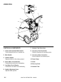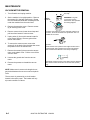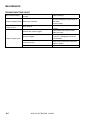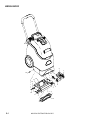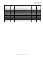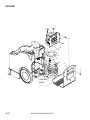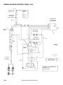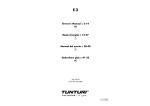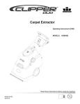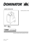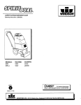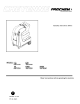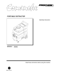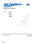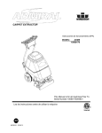
1
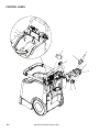
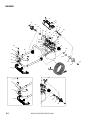
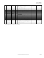
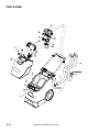
Mini Carpet Extractor
MODELS: MPRO
10080390
MPROEU
10080400
MPROGB
10080410
MPROAU
10080420
Operating Instructions (ENG)
86037780-U
08/15/08
(4 Gallon)
MACHINE DATA LOG/OVERVIEW
Model:
Date of Purchase:
Serial Number:
Sales Representative:
Address:
Phone Number:
Copyright 2006 Windsor Industries, Printed in USA
OVERVIEW
This carpet extractor is a mains powered, portable carpet extractor intended for commercial use.
The appliance sprays a cleaning solution onto the carpet, agitates the wet carpet, and then
extracts the soiled solution back into the unit’s recovery tank. The appliance can be fitted with an
accessory tool for cleaning upholstery and stairs.
2
86037780 EXTRACTOR 12/09/06
TABLE OF CONTENTS
Machine Data Log/Overview.........................2
Table of Contents..........................................3
HOW TO USE THIS MANUAL
How to use this Manual.................................1-1
SAFETY
Important Safety Instructions ........................2-1
Hazard Intensity Level ..................................2-2
Grounding Instructions..................................2-3
Safety Label Location ...................................2-4
OPERATIONS
Chemicals .....................................................3-1
Controls & Components................................3-2
Filling The Tanks...........................................3-3
Operating The Machine ................................3-4
Operating Machine With Accessory Tools ....3-4
PARTS LIST
Brush Deck ....................................... 5-1
Control Panel .................................... 5-3
Decal................................................. 5-5
Frame & Wheels ............................... 5-7
Handle .............................................. 5-9
Solution............................................. 5-11
Tank & Dome.................................... 5-15
Vacuum............................................. 5-17
Wiring Diagram-Control
Panel 115V ....................................... 5-19
Wiring Diagram-Vacuum, Brush Motor
& Pump 115V.................................... 5-21
Wiring Diagram-Control
Panel 230V ....................................... 5-23
Wiring Diagram-Vacuum, Brush Motor
& Pump 230V.................................... 5-25
Hose Diagram................................... 5-27
Spare Parts....................................... 5-28
Accessories ...................................... 5-28
MAINTENANCE
Protect From Freezing. .................................4-1
Daily/ Regular Maintenance..........................4-1
Periodic Maintenance. ..................................4-1
Brush Assembly ............................................4-2
Spray Jet ......................................................4-2
Brush Motor Removal ...................................4-3
Pump Removal .............................................4-3
Vacuum Removal..........................................4-5
Vacuum Carbon Brush Replacement ...........4-4
Troubleshooting Chart ..................................4-5
86037780 EXTRACTOR 12/09/06
3
HOW TO USE THIS MANUAL
This manual contains the following sections:
-
HOW TO USE THIS MANUAL
SAFETY
OPERATIONS
MAINTENANCE
PARTS LIST
The HOW TO USE THIS MANUAL section will tell
you how to find important information for ordering
correct repair parts.
Parts may be ordered from authorized dealers.
When placing an order for parts, the machine model
and machine serial number are important. Refer to
the MACHINE DATA box which is filled out during
the installation of your machine. The MACHINE
DATA box is located on the inside of the front cover
of this manual.
The model and serial number of your machine is
located on the lower back panel.
The SAFETY section contains important information
regarding hazardous or unsafe practices of the
machine. Levels of hazards are identified that could
result in product damage, personal injury, or severe
injury resulting in death.
The OPERATIONS section is to familiarize the
operator with the operation and function of the
machine.
The MAINTENANCE section contains preventive
maintenance to keep the machine and its
components in good working condition. They are
listed in this general order:
-
Periodic
Daily/Regular
Troubleshooting
The PARTS LIST section contains assembled parts
illustrations and corresponding parts list. The parts
lists include a number of columns of information:
-
-
REF – column refers to the reference
number on the parts illustration.
PART NO. – column lists the part
number for the part.
PRV NO. - Reference number.
QTY – column lists the quantity of the
part used in that area of the machine.
DESCRIPTION – column is a brief
description of the part.
SERIAL NO. FROM – column indicates
the first machine the part number is
applicable to. When the machine design
has changed, this column will indicate
serial number of applicable machine.
The main illustration shows the most
current design of the machine. The
boxed illustrations show older designs.
If column has an asterisk (*), call
manufacturer for serial number.
NOTES – column for information not
noted by the other columns.
NOTE: If a service or option kit is installed on your
machine, be sure to keep the KIT INSTRUCTIONS
which came with the kit. It contains replacement
parts numbers needed for ordering future parts.
NOTE: The manual part number is located on the
lower left corner of the front cover.
1-1
86037780 EXTRACTOR 12/09/06
SAFETY
IMPORTANT SAFETY INSTRUCTIONS
When using an electrical appliance, basic precaution
must always be followed, including the following:
READ ALL INSTRUCTIONS BEFORE USING THIS MACHINE.
This machine is for commercial use.
To reduce the risk of fire, electric shock, or injury:
Connect to a properly grounded outlet. See Grounding Instructions.
Do not leave the machine unattended. Unplug machine from outlet when not in use and before maintenance or
service.
Use only indoors. Do not use outdoors or expose to rain.
Do not allow machine to be used as a toy. Close attention is necessary when used by or near children.
Use only as described in this manual. Use only manufacturer’s recommended components and attachments.
Do not use damaged electrical cord or plug. Follow all instructions in this manual concerning grounding the
machine. If the machine is not working properly, has been dropped, damaged, left outdoors, or dropped into
water, return it to an authorized service center.
Do not pull or carry machine by electrical cord, use as a handle, close a door on cord, or pull cord around sharp
edges or corners.
Do not run machine over cord. Keep cord away from heated surfaces.
Do not unplug machine by pulling on cord. To unplug, grasp the electrical plug, not the electrical cord.
Do not handle the electrical plug or machine with wet hands.
Do not operate the machine with any openings blocked. Keep openings free of debris that may reduce airflow.
This machine is intended for cleaning carpet only.
Do not vacuum anything that is burning or smoking, such as cigarettes, matches, or hot ashes.
This machine is not suitable for picking up health endangering dust.
Turn off all controls before unplugging.
Machine can cause a fire when operating near flammable vapors or materials. Do not operate this machine near
flammable fluids, dust or vapors.
This machine is suitable for commercial use, for example in hotels, schools, hospitals, factories, shops
and offices for more than normal housekeeping purposes.
Maintenance and repairs must be done by qualified personnel.
If foam or liquid comes out of machine, switch off immediately.
SAVE THESE INSTRUCTIONS
86037780 EXTRACTOR 12/09/06
2-1
SAFETY
The following symbols are used throughout this guide as indicated in their descriptions:
HAZARD INTENSITY LEVEL
There are three levels of hazard intensity identified by signal words -WARNING and CAUTION and FOR
SAFETY. The level of hazard intensity is determined by the following definitions:
WARNING - Hazards or unsafe practices which COULD result in severe personal injury or death.
CAUTION - Hazards or unsafe practices which could result in minor personal injury or product or property
damage.
FOR SAFETY: To Identify actions which must be followed for safe operation of equipment.
Report machine damage or faulty operation immediately. Do not use the machine if it is not in proper operating
condition. Following is information that signals some potentially dangerous conditions to the operator or the
equipment. Read this information carefully. Know when these conditions can exist. Locate all safety devices on
the machine. Please take the necessary steps to train the machine operating personnel.
FOR SAFETY:
DO NOT OPERATE MACHINE:
Unless Trained and Authorized.
Unless Operation Guide is Read and understood.
In Flammable or Explosive areas.
In areas with possible falling objects.
WHEN SERVICING MACHINE:
Avoid moving parts. Do not wear loose clothing; jackets, shirts, or sleeves when working on the machine. Use
Windsor approved replacement parts.
2-2
86037780 EXTRACTOR 12/09/06
SAFETY
120 VOLT MODELS:
THIS PRODUCT IS FOR COMMERCIAL
USE ONLY.
ELECTRICAL:
In the USA this machine operates on a standard 15
amp 120V, 60 hz, A.C. power circuit. The amp,
hertz, and voltage are listed on the data label found
on each machine. Using voltages above or below
those indicated on the data label will cause serious
damage to the motors.
EXTENSION CORDS:
If an extension cord is used, the wire size must be at
least one size larger than the power cord on the
machine, and must be limited to 50 feet (15.5m) in
length.
GROUNDING INSTRUCTIONS:
This appliance must be grounded. If it should
malfunction or break down, grounding provides a
path of least resistance for electric current to reduce
the risk of electric shock. This appliance is equipped
with a cord having an equipment-grounding
conductor and grounding plug. The plug must be
inserted into an appropriate outlet that is properly
installed and grounded in accordance with all local
codes and ordinances.
This appliance is for use on a nominal 120-volt
circuit, and has a grounded plug that looks like the
plug in “Fig. A”. A temporary adaptor that looks like
the adaptor in “Fig. C” may be used to connect this
plug to a 2-pole receptacle as shown in “Fig. B”, if a
properly grounded outlet is not available. The
temporary adaptor should be used only until a
properly grounded outlet (Fig. A) can be installed by
a qualified electrician. The green colored rigid ear,
lug, or wire extending from the adaptor must be
connected to a permanent ground such as a
properly grounded outlet box cover. Whenever the
adaptor is used, it must be held in place by a metal
screw.
Improper connection of
the equipment-grounding
conductor can result in a risk of electric shock.
Check with a qualified electrician or service
person if you are in doubt as to whether the
outlet is properly grounded. Do not modify the
plug provided with the appliance - if it will not fit
the outlet, have a proper outlet installed by a
qualified electrician.
GROUNDED
OUTLET BOX
GROUNDED
OUTLET
ADAPTER
TAB FOR
GROUNDING SCREW
METAL SCREW
GROUNDING
PIN
(A)
(B)
86037780 EXTRACTOR 12/09/06
(C)
2-3
SAFETY
SAFETY LABEL LOCATION
The following WARNING LABEL(S) are found on your cleaning unit. These labels point out important Warnings
and Cautions which should be followed at all times. Failure to follow warnings and cautions could result in fatality,
personal injury to yourself and/or others, or property damage. Follow these instructions carefully! DO NOT
remove these labels.
NOTE: If at any time the labels become illegible, promptly replace them.
WARNING LABEL
PART NUMBER 86220140
PRV 500895
2-4
86037780 EXTRACTOR 12/09/06
OPERATION
To avoid electric shock
use indoors only.
To reduce risk of fire, do not use volatile substances.
Use only cleaners intended for carpet application.
INSPECTION
Carefully unpack and inspect your extractor for
shipping damage. Each unit is operated and
thoroughly inspected before shipping, and any damage
is the responsibility of the carrier, who should be
notified immediately.
To avoid possible
distortion of
polyethylene solution/recovery tanks, DO NOT USE
WATER TEMPERATURE THAT EXCEEDS 140 F
(60 C).
CHEMICALS
Use only the suitable chemicals listed below. Using
incompatible chemicals will damage the machine.
Damages of this type are not covered under
warranty. Carefully read ingredients on
manufacturer’s label before using any product in this
machine.
Suitable
Chemicals
Alkalis
Defoaming Agents
Detergents
Soaps
Vinegar
Hydroxides
86037780 EXTRACTOR 12/09/06
Incompatible
Chemicals
Aldehydes; Butyls
Carbon Tetrachloride
Chlorinated Bleaches
Chlorinated Hydrocarbons
Trichlorethylene
Phenols; Methyls (MEK)
Perchlorethylene (perc)
Aromatic Hydrocarbons
D-Limonene
3-1
OPERATION
5
1
4
2
11
10
12
3
9
13
6
7
8
CONTROLS & COMPONENTS
7. Solution Tank Drain Hose
1. Power and Operation Mode Switch
Turns accessory tool on or machine on.
8. Accessory Tool Connection
Solution connection for accessory tools.
2. Main Handle
9. Accessory Hose Connection
Hose connection for accessory tool.
3. Solution Button
Sprays solution on floor when pressed.
10. Dome Clamp
4. Brush Motor Circuit Breaker
Protects brush motor from overheating.
11. Dome
12. Recovery Tank
5. Vac Motor Circuit Breaker
Protects the vac motor from overheating
13. Solution Tank
6. Handle Adjustment Lever
Adjusts handle position.
3-2
86037780 EXTRACTOR 12/09/06
OPERATION
OPERATING INSTRUCTIONS
FILLING THE SOLUTION TANK
SPECIAL NOTES:
1. Release dome clamp.
This appliance is not intended for use by persons
(including children) with reduced physical, sensory
or mental capabilities, or lack of experience and
knowledge, unless they have been given supervision
or instruction concerning use of the appliance by a
person responsible for their safety. Children should
be supervised to ensure that they do not play with
the appliance.
2. Lift upper recovery tank from machine and
set aside.
3. Use a clean bucket, recovery tank or hose to
fill solution tank with hot water. The solution
tank holds 4 gallons (15.2 liters) of cleaning
solution.
4. Add a non-foaming concentrate for use in
hot water extractors at the proportions noted
on the container.
NOTE: Periodically operate the extractor with only
hot water to remove chemical residue in carpet.
To avoid possible distortion of the polyethylene
solution/recovery tanks, DO NOT USE WATER
WITH A TEMPERATURE THAT EXCEEDS 140°F
(60°C).
5. Place recovery tank back on machine.
The sound pressure level at the operator’s ear was
measured to be 73.7 dBA. This was a nearfield,
broad-band measurement taken in a typical
industrial environment on a tile floor. This appliance
contains no possible source of impact noise. The
instantaneous sound pressure level is below 63 Pa.
The weighted root mean square acceleration at the
2
operator’s arms was measured to be below 2.5m/s .
This was a tri-axial, third-octave-band measurement
made during normal operation on a composite tile
floor. The measurement and related calculations
were made in accordance with ISO 5349-1.
6. Place dome on recovery tank. Make sure
dome is seated correctly to ensure proper
vacuum seal. Clamp dome securely to
recovery tank.
Use only the suitable chemicals listed in the
Chemical Section. Using incompatible
chemicals will damage the machine. Carefully
read ingredients on manufacturer’s label before
using any product in this machine.
86037780 EXTRACTOR 05/09/08
3-3
OPERATION
OPERATING THE MACHINE
1. Vacuum the carpet and make sure it is cleared
of surface debris before cleaning.
2. Plug power cord into a grounded wall outlet.
NOTE: Defeating the grounding pin on the power
cord can result in a severe electrical shock.
3. Turn on the machine by pressing the switch in
the normal operation mode.
NOTE: The vacuum and the brush are protected by
circuit breakers located on the control panel, to the
right of the switch.
NOTE: If either motor does not respond to
being switched on, reset the circuit breakers by
pressing them in, and attempt to switch the
machine on again.
NOTE: If solution does not dispense in an even
pattern across the width of the machine, the spray
jet may be clogged. Tilt the machine back, check
for debris and clean surface of jet.
OPERATING MACHINE WITH
ACCESSORY TOOLS
This extractor is easily adapted for use with Windsor
accessory tools: Contact Customer Service for details.
1.
Disconnect vacuum hose at dome, insert hose cuff
into the dome, ensuring that there is a tight fit.
Dome must be clamped to recovery tank.
2.
Attach the solution hose from accessory tool to the
brass solution fitting on the back of machine.
3.
Turn on the switch in the accessory position. The
application of cleaning solution is now controlled
by the lever on the accessory tool.
NOTE: The solution pump is not intended to run dry.
When using the extractor for vacuum pick-up only.
Do not press the solution spray button.
CAUTION: This appliance is not suitable for picking
up hazardous dust.
NOTE: Do not use pins, wire, etc. to clean spray jet
nozzle as this will deform the jet and destroy the
spray pattern.
4.
While operating machine, check for excessive
foam buildup in the recovery tank. If excessive
foam is present, add a defoamer solution to
recovery tank, or empty tank.
5. Empty recovery tank when approximately 3/4
full. If the recovery tank is overfilled, the water
will drain back onto the carpet when the vacuum
is switched off.
6. Ventilate area after carpet has been cleaned.
Keep children and pets away and do not walk on
carpet until it is dry.
A Windblower™ fan can be used to reduce drying
time.
3-4
86037780 EXTRACTOR 05/09/08
MAINTENANCE
PROTECT FROM FREEZING
PERIODIC MAINTENANCE
If it becomes necessary to store in temperatures that
could drop below 40°F, the pumping system, hoses
and valves must be protected from freezing with a
methyl hydrate window washer antifreeze solution.
1. After every 25 hours of operation, flush a white
vinegar solution (ONE quart vinegar to two
gallons of water) or anti-browning solution (mixed
as directed) through the extractor. This will
prevent build-up of alkaline residue in the system.
NOTE: Do not use ethylene glycol or cooling system
antifreezes.
1. Add one gallon of window washer antifreeze to
the supply tank.
2. Turn on pump switch and spray until the
anti-freeze solution fills the solution lines.
3. Drain the leftover antifreeze from the supply tank.
Always allow the unit to reach room temperature
before filling with hot water or operating.
4. Before operation be sure to flush system
completely. Failure to do so after winterizing
machine will damage carpet.
DAILY/REGULAR MAINTENANCE
Before making any
adjustments or repairs to
the machine, disconnect the power cord from the
electrical source.
1. Empty unused cleaning solution from the
solution tank.
2. Inspect and clean filter at solution tank fill port
and at the vacuum intake port in the dome.
2. If the spray jet becomes clogged, check for debris
and clean surface of jet.
NOTE: Do not use pins, wire, etc. to clean spray jet
nozzle as this will deform the jet and destroy the
spray pattern.
3. Periodically inspect all hoses, electrical cables,
filters, gaskets and connections on your machine.
Frayed or cracked hoses should be repaired or
replaced to eliminate vacuum or solution
pressure loss.
4. The electrical cable must be well insulated, if the
cable insulation is broken or frayed, repair or
replace it immediately. Don't take chances with
electrical fire or shock.
5. The filter in the bottom of the solution tank and at
the fill port must be clean to allow free flow of
cleaning solution. The screen filter on the vacuum
intake in the dome must be free of lint buildup to
ensure full vacuum strength.
6. The dome gasket must be properly seated and
free of damage to create the air seal needed to
extract water.
3. Flush pumping system with 1 to 2 gallons of
clean, hot water.
4. Check spray jet for full spray pattern.
5. Empty the recovery tank and rinse with clean
water.
6. Check for and remove any lint or debris around
brush and vac shoe.
7. Clean float screen and check float valve to make
sure it moves freely.
86037780 EXTRACTOR 05/09/08
4-1
MAINTENANCE
MAINTENANCE INSTRUCTIONS
SPRAY JET
Remove machine power
cord from electrical source
before making any adjustments or repairs to the
machine.
Note: To prevent a clogged jet due to alkali build-up,
the spray system should be flushed with 1 to 2
gallons of clean hot water at the end of each day.
Only qualified maintenance
personnel are to perform
repairs.
BRUSH ASSEMBLY
1. Turn off switch and unplug machine.
2. Position the machine to have access to the
bottom. Remove screws (2) at the sides of the
machine holding the brush deck pivot axle.
3. Remove screw mounting belt cover and remove
belt cover.
4. Loosen the nuts (2) at brush motor and slide
motor forward to reduce belt tension. Remove
belt.
5. Loosen set screw on brush pulley. Remove
pulley.
6. Remove screws (4) mounting brush bearings to
frame. Slide bearing off brush axle.
1. Turn off switch and unplug machine.
2. Position the machine to have access to the
bottom. Remove screws (2) at the sides of
the machine holding the brush deck pivot
axle.
3. Position the machine to have access to the
bottom.
4. Pull off the clip mounting the jet to the frame.
Push the jet and hose out of the mounting
hole in the frame.
5. Loosen the hose clamp and pull the jet out
of the hose.
6. Reverse the process to reinstall the jet. Be
sure to have jet rotated correctly before
installing clip. Clip tab must face back of
machine.
Note: Do not use pins or wire to remove obstruction
if clogged, this may damage jet and alter spray
pattern.
7. Remove brush by lifting drive end out of frame
and sliding other end out of bearings mounted to
frame.
8. Inspect/replace brush and bearings as required.
The brush is equipped with yellow wear indicator
bristles. Replace the brush when it wears down
to the height of the yellow bristles.
9. Reverse the process to reinstall the brush and
bearings. Check belt for proper belt tension.
Only use the brushes provided with the
appliance or those specified in the instruction
manual. The use of other brushes may impair
safety.
4-2
86037780 EXTRACTOR 05/09/08
MAINTENANCE
BRUSH MOTOR REMOVAL
PUMP REMOVAL
1. Turn off switch and unplug machine.
1. Turn off switch and unplug machine.
2. Set the machine in its upright position. Remove
the screws (2) in the back metal cover. Rotate
the cover down and slide back releasing the tab
under the machine from the main frame.
2. Set the machine in its upright position. Remove
the screws (2) in the back metal cover. Rotate
the cover down and slide back releasing the tab
under the machine from the main frame.
3. Remove the pump box cover. Remove screws
(4) at each leg of the cover.
3. Remove the pump box cover. Remove screws
(4) at each leg of the cover.
4. To remove brush motor, position the machine to
have access to the bottom. Remove screws (2)
at the sides of the machine holding the brush
deck pivot axle.
4. To remove either pump, loosen the hose clamp
and remove the hose from both ends of the
pump.
5. Remove screw mounting belt cover and remove
belt cover.
6. Remove the nuts and washers (2) at brush
motor and slide motor forward to reduce belt
tension. Remove belt.
7. Remove pulley by loosening set screw and pull
off shaft.
8. Unplug the brush motor wires from the rectifier
located in the pump mount housing. Also,
remove the ground lug from the stud on the
main frame by removing the nut on the stud.
5. Remove screws and washers (4) that mount
pump housing.
6. Unscrew the hose fittings from each end of the
pump.
7. Flex the pump mounting housing to remove the
pump.
8. Remove the screw attaching the ground wire to
the pump. Remove the other two wire
connectors attached to the pump.
9. Reverse the process to reinstall the pump.
9. Reverse the process to reinstall the motor. Align
motor pulley with brush pulley. Check belt for
proper belt tension.
86037780 EXTRACTOR 11/21/07
4-3
MAINTENANCE
VACUUM MOTOR REMOVAL
Vacuum Motor Carbon Brushes Replacement
End Cap
1. Turn off switch and unplug machine.
2. Set the machine in its upright position. Remove
the screws (2) in the back metal cover. Rotate
the cover down and slide back releasing the tab
under the machine from the main frame.
Carbon
Brushes
WARNING: The green
ground wire must be
attached for safe operation.
See wiring diagram.
3. Remove the pump box cover. Remove screws
(4) at each leg of the cover.
4. Remove vacuum hose, loosen hose clamp and
pull hose from bottom of vacuum motor.
If armature commutator is grooved, extremely pitted or not
concentric, the motor will need to be replaced or sent to a
qualified service center.
5. Unplug wires (2) from main harness located in
pump mount housing. Remove ground from
stud on main frame.
6. To remove the vacuum motor, remove the
screws (2) in the back of the machine that mount
the plastic cover to the solution tank.
7. Remove the screws (3) that mount the vacuum
motor to the plastic cover. Pull the cover off the
vacuum motor.
Important:
These brushes wear quicker as the length shortens due to
increased heat. Spring inside brush housing will damage
motor if brushes are allowed to wear away completely.
8. Unscrew the ground wire from the vacuum
motor.
9. Reverse the process to reinstall the vacuum
motor.
3 [9.5mm]
8
Periodically check the length of the carbon brushes. Replace
both carbon brushes when either is less than 3/8" (9.5mm)
long.
NOTE: Make sure the excess wire lengths do not
get pinched between the vacuum motor and plastic
cover.
The vac motor is protected by a circuit breaker
located in the switch panel. The breaker will only
trip under conditions of abuse.
4-4
86037780 EXTRACTOR 12/09/06
MAINTENANCE
TROUBLESHOOTING CHART
PROBLEM
No power, nothing runs
Vacuum motor will not
run
Vacuum motor runs but
suction is poor
Poor or no water flow
(carpet is streaky)
Brush does not spin
Accessory tool fitting
difficult to connect
CAUSE
SOLUTION
Is the cord plugged in.
Circuit breaker tripped in building.
Faulty switch.
Faulty power cord or pigtail.
Plug in cord.
Reset breaker
Call for service.
Call for service.
Vacuum circuit breaker tripped.
Faulty main switch.
Loose wiring.
Faulty vac motor.
Reset breaker
Call for service.
Call for service.
Call for service.
Debris lodged in vac shoe.
Dome gasket defective or missing.
Vacuum hose cracked or hose cuff loose.
Recovery tank full.
Remove debris from vac shoe.
Replace as necessary.
Replace or repair as necessary.
Turn off vac motor. Drain and rinse
recovery tank.
Switch to accessory mode.
Jets clogged or missing.
Faulty solution pump.
Turn to deep clean position.
Clean using a vinegar /water solution or
replace.
Drain solution tank and clean solution
filter.
Call for service.
Switch in accessory mode.
Brush circuit breaker tripped.
Brush belt broken.
Faulty brush motor.
Turn to deep clean position.
Reset circuit breaker.
Replace as necessary.
Call for service.
Solution filter clogged.
Corrosion on fitting.
Clean with steel wool.
Remove and soak in acetic acid (white
vinegar).
Lubricate lightly with silicone base
lubricant.
86037780 EXTRACTOR 12/09/06
4-5
MAINTENANCE
TROUBLESHOOTING CHART
Worn brush bearings
Squealing or grinding sound in brush
housing.
Carpet not getting clean Severe soil conditions
Carpet too wet
Worn spray jet
Solution filter screen clogged.
Spray jet clogged.
Carpet not getting wet
Pump not running.
Faulty solution switch.
4-6
Replace bearings.
Make several passes at right angles to
each other.
Use a pre-spray.
Replace spray jet which is producing a
fine mist.
Clean solution filter screen located
inside lower tank.
Clean or replace jet. Do not use a wire
to clean jet. Damaged jet will cause
over-saturation.
Check for and correct any loose wires.
Repair or replace.
Replace switch in handle.
86037780 EXTRACTOR 12/09/06
Mini Carpet
Extractor
Parts List
86037780 EXTRACTOR 12/09/06
BRUSH DECK
2
1
3
15
16
8
11
9
10
4
13
5
7
12
6
1
7
14
5-1
86037780 EXTRACTOR 03/27/07
1
BRUSH DECK
REF
1
2
3
4
5
6
7
8
9
10A
10B
11
12
13
14
15
16
PART
NO.
86173020
86217390
86215260
86223780
86223300
86214970
86229020
86005640
86173330
86247110
86306720
86217920
86223490
86216430
86216040
86173220
86223350
PRV NO.
QTY
70916
270146
11051
70896
64115
03124
09163
57030
87513
53146
140893
67468
140912
02506
70954
64125
5
1
1
2
1
1
2
2
2
1
1
1
2
2
1
2
1
DESCRIPTION
SCR, M5 X 10, PHMS, ISO7045, SS
COVER, PULLEY, BRUSH DECK
BELT, HTD 5MM 69T 9 WIDE
SET SCR, M4 X 6LG, CP BLK
PULLEY, BRUSH
AXLE, PIVOT, BRUSH DECK
BEARING, BRUSH PLASTIC
NUT, 10-32 HEX NYLOCK
WASHER, M5, FLAT, ISO7093, SS
MOTOR, 115V BRUSH DRIVE
MOTOR ASM, 230V DC PM
BRKT, FLOATING BRUSH, 10 IN
RING, 10MM EXT SNAP, DIN 471
BUSHING, BRUSH PRESSURE
BRUSH, CHEVRON, 10 IN
SCR, M6X12 PHCS, 12.5MM HD,SS
PULLEY, MOTOR
86037780 EXTRACTOR 02/15/08
SERIAL NO.
FROM
NOTES:
115V ONLY
230V ONLY
5-2
CONTROL PANEL
11
10
9
8
2
1
7
3
4
6
5-3
86037780 EXTRACTOR 02/15/08
5
CONTROL PANEL
REF
1
2
3
4
5A
5B
6A
6B
7
8
9
10
11
PART
NO.
86007200
86002010
86173140
86217410
86230140
86001780
86291460
86198130
86223420
86302680
86292300
86173350
86216300
PRV
NO.
72162
14942
70945
270152
14622
14308
141047
67622
87515
140956
QTY
1
2
2
1
1
1
1
1
1
1
2
2
2
DESCRIPTION
SWITCH, DPDT 3-POSITION ROCKER
BOOT, 3/8 CIRCUIT BREAKER
SCR, KA40X16, PT OVAL, WN1412, PL
COVER, CONTROLS TOP
BREAKER, 1.5A CIRCUIT
BREAKER, 0.8A CIRCUIT
BREAKER, 11A VDE CIRCUIT
BREAKER, 6A VDE CIRCUIT
RELAY, 10A 230VAC SPDT
EMI FILTER MAIN
SCR, M4X20 SBHCS, BLK EDP
WASHER, M5, FLAT, ISO7089, SS
BUMPER, CONSOLE
SERIAL NO.
FROM
NOTES:
115V ONLY
230V ONLY
115V ONLY
230V ONLY
230V ONLY
230V ONLY
SEE WIRING DIAGRAM FOR WIRE CONNECTIONS.
86037780 EXTRACTOR 02/15/08
5-4
DECAL
2
1
3
5-5
86037780 EXTRACTOR 03/22/07
DECAL
REF
1
2
3
PART
NO.
86221090
86221470
86013720
PRV NO.
QTY
501128
501208
-
1
1
1
DESCRIPTION
SERIAL NO.
FROM
NOTES:
LABEL, CONTROL PANEL
LABEL, DOME ACCESSORY
LABEL, MINI EXT.INSTRUCTION
86037780 EXTRACTOR 12/09/06
5-6
FRAME & WHEELS
8
10
1
9
2
11
3
7
13
6
4
5
5-7
86037780 EXTRACTOR 03/22/07
12
FRAME & WHEELS
REF
1
2
3
4
5
6
7
8
9
10
11
12
13
PART
NO.
86215830
86173010
86216290
86218090
86225530
86172630
86173220
86226050
86011880
86214980
86272750
86219480
86291130
PRV NO.
QTY
140897
70915
140895
35360
85086
57314
70954
89279
03125
67010
41567
-
1
6
1
1
1
6
6
2
2
1
2
2
1
DESCRIPTION
SERIAL NO.
FROM
NOTES:
BRKT, BRUSH HOUSING, 10 IN
SCR, M4 X 16, SHCS, ISO4762, SS
BUMPER, EXTRACTOR, FRONT
GASKET, VAC SHOE
VAC SHOE, 12 IN
NUT, M4, LOCK, ISO7040, SS
SCR, M6X12 PHCS, 12.5MM HD, SS
WHEEL, 10IN
WASHER, 16.2 X 23 X 0.6MM, PLT
AXLE, WHEELS, 5/8 DIA
RING, 5/8 EXTERNAL SNAP
HUBCAP, 9.75” WHEEL
BUMPER, BRUSH DECK
86037780 EXTRACTOR 05/09/08
5-8
HANDLE
26
27
38
13
23
18
22
21
17
44
33
19
28
45
20
32
25
24
49
46
48
31
36
34
37
24 29
36
31
8
40
50
5
41
37
30
13
42
35
43
7
47
6
14
1
16
2
15
3
9
4
10
11
12
5-9
86037780 EXTRACTOR 07/18/08
HANDLE
1
2
3
4
5
6
7
8
9
10
11
12
13
14
15
16
17
18
19
20
21
22
23
24
25
26
27
28
29
30A
30B
30C
31
32
33
34
35
36
37
38
39
PART
NO.
86012660
86218570
86225910
86218560
86225140
86224650
86216470
86219460
86216440
86219660
86221790
86217360
86277600
86008650
86222600
86224150
86222340
86259430
86173220
86224930
86224460
86224140
86217380
86010640
86270800
86217350
86172870
86215520
86233170
86217140
86288380
86217030
86173030
86005640
86218230
86218220
86013730
86173320
86006770
86288680
OPEN
40
86296620
-
41
42
43
44
45
46
47
48
49
50
86292550
86296610
86296600
86292560
86266630
86297150
86297160
86298790
86173140
86266080
70945
76040
REF
PRV NO.
QTY
38342
38343
38341
72204
730392
140922
41553
140934
48113
51548
270138
70882
80604
66887
730405
57512
87485
70954
730012
730406
730404
270144
87016
57014
270135
70898
140921
20054
23732
23706
23710
70917
57030
35376
35375
87510
70323
87230
-
3
1
1
1
1
1
1
1
1
1
1
1
3
1
1
1
1
1
4
1
1
1
1
2
1
1
4
1
1
1
1
1
3
1
1
1
1
3
2
4
AS
REQ’D
1
1
1
1
1
1
1
1
4
1
DESCRIPTION
SERIAL NO.
FROM
SCR, KA40X25, PT OHCS, WN1452,PL
HANDLE, GRIP BOTTOM
WELDMENT, HANDLE TUBE
HANDLE, GRIP TOP
SWITCH, MICRO
SPRING, LEVER
BUTTON, SPRAY HANDLE
HUB, SPLINE HANDLE
BUSHING, SHAFT HANDLE
KEY, HANDLE CAM, 4X24MM
LEVER CAM HANDLE
COVER, TUBE HUB LEFT
SCR, M4 X 20, PHMS, ISO7045, SET
COTTER, 1/4” RING
PIN, CLEVIS 5MM
SHAFT, HANDLE CAM
NUT, M12, LOCK. ISO 7040, SST
WASHER, M12 FLAT
SCR, M6X12 PHCS, 12.5MM HD, SS
STRAIN RELIEF, 14/3 STRAIGHT
SPACER, SHAFT HANDLE
SHAFT, HANDLE
COVER, TUBE HUB RIGHT
WASHER, #10 LOCK EXT STAR
NUT, 10-32 HEX SS
COVER, CONTROLS, BOTTOM
SCR, M4X14 PHMS, DIN7985 SST
BRACKET, HANDLE AXLE
CLAMP, 3/8 NYLON UL/CSA
CORD ASM, 14X3 SJTX25’
CORD ASM, AB EURO
CORD ASM, AUST AB
SCR, M4 X 6, PHMS, ISO7045, PL
NUT, 10-32 HEX NYLOCK
GASKET, CONTROL BOX RIGHT
GASKET, CONTROL BOX LEFT
SHEILD, MICROSWITCH
WASHER, FLAT M4 DIN125 SST
SCR, 10-32 X 1/4 PH PLTD
WASHER, M5 RIVET BACKUP
WASHER, 0.2X19.8X25.0MM PLTD
BUSHING, HANDLE LOCK
LEVER, CAM HANDLE
COVER, HUB TUBE LEFT
SHAFT, HANDLE LOCK
PIN, DOWEL 5 X 25MM, PLTD
HANDLE, GRIP TOP
HANDLE, GRIP BOTTOM
WELDMENT, HANDLE TUBE
SCR, KA40 X 16, PT OHCS, WN1452PL
TERM, 18G .25 FEMALE COUPLER
86037780 EXTRACTOR 08/15/08
NOTES:
115V ONLY
230V ONLY
230V ONLY
1008039000001
1008039000001
1008039000001
1008039000001
1008039000001
1008039000001
1008039000126
1008039000126
1008039000126
1008039000126
5-10
SOLUTION
5-11
86037780 EXTRACTOR 11/21/06
SOLUTION
REF
1A
1B
2
3
4
5
6
PART
NO.
86201110
86201120
86240520
86010640
86006770
86215450
86304750
PRV
NO.
250-78
250-78A
40097
87016
70323
140930
-
QTY
2
2
4
2
2
1
1
DESCRIPTION
PUMP, 110/120 60HZ FLOJET
PUMP, 220/240V 50HZ FLOJET
HOSEBARB, 1/8MPT X 1/4 90D
WASHER, #10 LOCK EXT STAR
SCR, 10-32 X 1/4 PHTR PLTD
BOX, PUMP MOUNT
SHEILD, PUMP ENCLOSURE
86037780 EXTRACTOR 11/21/07
SERIAL NO.
FROM
NOTES:
115V ONLY
230V ONLY
1008039000126
5-12
SOLUTION
5-13
86037780 EXTRACTOR 03/22/07
SOLUTION
1
2
3
4
5
6
7
PART
NO.
86219580
86216810
86219200
86172950
86233150
86219090
86200820
8
86219070
39726
1
9
10
11
12
13
14
15
16
17
18
86219070
86233090
86288390
86219050
86240430
86012680
86005640
86010640
86219060
86291670
39727
20016
40062
39724
40083
57030
87016
39725
-
1
7
1
1
1
1
1
1
1
1
REF
PRV NO.
QTY
44106
270131
40114
70909
20042
39728
270-11A
1
1
1
4
3
1
1
DESCRIPTION
SERIAL NO.
FROM
NOTES:
JET, RT ANG, 1/4 BARB
CLIP, SHAFT, 9-12MM
HOSEBARB, 3/8MPT, 2 X 1/4. 1 X 3/8
SCR, M5X12, SHCS, ISO4762, SS
CLAMP, 3/8 HOSE (D-SLOT)
HOSE, 3/8” X 432MM CLEAR
NIPPLE, 1/8FPT QD MALE BRASS
HOSE ASM, 6MM X 610MM
NYLOBRAID
HOSE, 6MM X 245MM NYLOBRAID
CLAMP, 1/4 ID HOSE
HOSEBARB, TEE 3/8 X 3/8 X 1/4
HOSE, 6MM X 390MM NYLOBRAID
HOSEBARB, 3/8 MPT X 3/8 NYLON
HOSE, 3/8ID X 60MM NYLOBRAID
NUT, 10-32 NYLOCK
WASHER, #10 LOCK EXT STAR SS
HOSE, 6MM X 420MM NYLOBRAID
COVER, PUMP BOX
SEE HOSE DIAGRAM FOR HOSE ROUTING.
86037780 EXTRACTOR 03/27/07
5-14
TANK & DOME
5-15
86037780 EXTRACTOR 11/21/07
TANK & DOME
1
2
PART
NO.
86225240
86002390
3
86011910
-
2
4
5
6
7
8
86291230
86217700
86291170
86291190
86007970
28070
73864
1
1
1
1
1
9
86172940
70908
6
10
11
12
13
14
15
16
17
18
86224960
86172990
86218530
86228260
86216770
86215970
86173350
86291180
86291210
730373
70913
38338
75472
22113
141049
87515
-
1
4
1
1
1
2
4
1
1
19
86173000
70914
2
20
21
86291220
86292450
-
2
1
REF
PRV NO.
QTY
DESCRIPTION
75471
20063
1
2
TANK, SOLUTION, EXTRACTOR
CLAMP, 1.75” WORM GEAR X .312
HOSE ASM, 1.5X34” VAC
W/ELBOW
GASKET, DOME, MINI PRO
DOME
DOME, PLATE INTERIOR
SCREEN, VACUUM INTAKE
STRAINER, 3/8 IN. NPT 60 MESH
SCR, KA40X10,PT OVAL,
WN1412,PL
STRAINER, BASKET
SCR, M6X12 BHCS, ISO7380, SS
HANDLE, RECOVERY TANK
TANK, RECOVERY, EXTRACTOR
CLAMP, DOME
BRKT, DOME CLAMP
WASHER, M5, FLAT, ISO7089, SS
DUCT, VACUUM INTAKE
O-RING, 26MM ID X 2MM THICK
SCR, KA40X20, PT OVAL,
WN1412,PL
SCR, KA40X20, FLATHEAD, SS
GASKET, DUCT
86037780 EXTRACTOR 01/18/08
SERIAL NO.
FROM
NOTES:
5-16
VACUUM
1
3
4
8
6
7
5
3
2
(GROUND
WIRE)
5-17
86037780 EXTRACTOR 03/22/07
VACUUM
REF
PART
NO.
PRV NO.
QTY
1
86173000
70914
3
2A
2B
3
4
5
6
7
8
86225480
86308980
86173220
86217420
86217370
86006770
86010640
86291680
53272
70954
270703
270140
70323
87016
-
1
1
4
1
1
1
1
1
DESCRIPTION
SCR, KA40x20, PT OHS, WN1412,
PLTD
VAC MOTOR, 120V 5.7 3ST W/TUBE
VAC MOTOR ASM, 230V MINIPRO
SCR, M6X12 PHCS, 12.5MM HD, SS
COVER, VAC MOTOR
COVER, LOWER BACK
SCR, 10-32 X 1/4 PHTR PLTD
WASHER, #10 LOCK EXT STAR
GASKET, VAC MOTOR
86037780 EXTRACTOR 02/15/08
SERIAL NO.
FROM
NOTES:
115V ONLY
230V ONLY
5-18
WIRING DIAGRAM-CONTROL PANEL 115V
GROUND
SCREW
NC
NO C
HANDLE
MICRO SWITCH
3 CONDUCTOR
18 GUAGE
BLACK SHEATH
YEL
RED
3
6 CONDUCTOR
14/16 GUAGE
BLACK SHEATH
CONNECTOR
YEL
RED
RED
GRN
GRN
BRN
GRN
WHT
WHT
BLK
GRN
BLU
PEM
STUD
BLK
1
11A BREAKER
VAC MOTOR
BLK
4
3 CONDUCTOR
12 GUAGE
YELLOW SHEATH
BLK
1.5A BREAKER
BRUSH MOTOR
BLK
BLK
BLU
2
YEL
RED
MODE
SWITCH
3
2
1
6
5
4
TOP OF
MACHINE
BLK
P/N 880464
BLK
MODE SWITCH
FRONT OF CONSOLE
"BACK
POSTION"
5-19
"FORWARD
POSITION"
86037780 EXTRACTOR 11/21/07
FORWARD = ACCESSORY TOOL
CENTER = OFF
BACK = EXTRACT
WIRING DIAGRAM – CONTROL PANEL 115V
REF
1
2
3
4
PART
NO.
86218840
86226230
86218830
86226250
PRV NO.
QTY
DESCRIPTION
41573
880464
41572
880466
1
1
1
1
HARNESS, MAIN
WIRE ASM, CONTROL PANEL JUMPER
HARNESS, HANDLE
WIRE, 14” BLACK/14 76010
86037780 EXTRACTOR 11/21/07
SERIAL NO.
FROM
NOTES:
5-20
WIRING DIAGRAM-VACUUM, BRUSH MOTOR & PUMP 115V
DASH LINE = PUMP BOX OUTLINE
RED
GRN
PUMP
ACC
WHT
1
WHT
GRN
PUMP
MAIN
RED
BRN
BRN
GRN
WHT
BLK
BLU
BLK
FULL
BRIDGE
RECT
WHT
BLU
CONNECTOR
2
WHT
GRN
BLK
GRN
BOTTOM OF
MACHINE
4
GRN
GRN
GRN
BRUSH
MOTOR
PEM
STUD
WHT
G
R
N
WHT
GRN
VAC
MOTOR
BLK
1
3
G
R
N
GRN
BACK COVER
5-21
86037780 EXTRACTOR 11/21/07
WIRING DIAGRAM – VACUUM, BRUSH MOTOR & PUMP 115V
1
2
PART
NO.
86226250
86223390
3
86303670
-
1
4
86303680
-
1
REF
PRV NO.
QTY
88884
67488
3
1
DESCRIPTION
SERIAL NO.
FROM
NOTES:
WIRE, 14” GRN/14 76008 X 76008
RECTIFIER, 50A 600V BRIDGE
WIRE ASM, 18 GA GRN
76008/76040
WIRE ASM, 18 GA GRN
76008/76042
86037780 EXTRACTOR 11/21/07
5-22
WIRING DIAGRAM-CONTROL PANEL 230V
GROUND
SCREW
NC
NO C
MICRO
SWITCH
3 CONDUCTOR
18 GUAGE
BLACK SHEATH
YEL
RED
6 CONDUCTOR
14/16 GUAGE
BLACK SHEATH
2
YEL
GRN
GRN
RED
RED
BRN
GRN
WHT
BLK
GRN
BLU
GRN
6A BREAKER
VAC. MOTOR
PEM
STUD
BLK
BLK
R
E
D
WHT
.8A BREAKER
BRUSH MOTOR
EMI
FILTER
8
B
R
N
B
R
N
1
BLK
W
H
T
YEL
B
L
U
MODE
SWITCH
B
L
U
BLU
W
H
T
RED
3
2
1
6
5
4
3
TOP OF
MACHINE
5
W
H
T
B
L
K
6
WHT
FRONT OF CONSOLE
BLK
3 CONDUCTOR
12 GUAGE
YELLOW SHEATH
O
R
G
W
H
T
"BACK
POSTION"
7
"FORWARD
POSITION"
4
5
3
1
6
4
2
7
R
E
D
8
RELAY
9
5-23
86037780 EXTRACTOR 02/15/08
FORWARD = ACCESSORY TOOL
CENTER = OFF
BACK = EXTRACT
WIRING DIAGRAM – CONTROL PANEL 230V
REF
1
2
3
4
5
6
7
8
9
PART
NO.
86218840
86218830
86012400
86012420
86226250
86012430
86012410
86302680
86223420
PRV NO.
QTY
41573
41572
880466
67622
1
1
1
1
1
1
1
1
1
DESCRIPTION
SERIAL NO.
FROM
NOTES:
HARNESS, MAIN
HARNESS, HANDLE
WIRE ASM, 18GA 4” BLK
WIRE ASM, 18GA RED
WIRE, 14” BLACK/14 76010
WIRE ASM, 18GA WHT
WIRE ASM, 18GA 4” ORG
ASM, FILTER EMI MAIN
RELAY, 10A 230VAC SPDT
86037780 EXTRACTOR 02/15/08
5-24
WIRING DIAGRAM-VACUUM, BRUSH MOTOR & PUMP 230V
DASH LINE = PUMP BOX OUTLINE
RED
GRN
PUMP
ACC
WHT
1
BRN
GRN
GRN
PUMP
MAIN
RED
BRN
GRN
WHT
WHT
1
BLK
BLU
BRN
B
L
K
W
H
T
FULL
BRIDGE
RECT
WHT
B
L
K
W
H
T
BLU
BLU
3
GRN
GRN
GRN
GRN
5
BOTTOM OF
MACHINE
WHT
8
FERRITE
GRN
BLU
GRN
GRN
BRN
EMI FILTER
WHT
GRN
BRUSH
MOTOR
BLK
BLK
GRN
2
4
8
7
WHT
GRN
WHT
GRN
GRN
VAC
MOTOR
FERRITE
BLK
6
BACK COVER
5-25
86037780 EXTRACTOR 05/26/08
FERRITE
BLK
WIRING DIAGRAM-VACUUM, BRUSH MOTOR & PUMP 230V
1
2
3
PART
NO.
86226310
86308960
86223390
4
86303680
-
1
5
86303670
-
1
6
7
8
86302670
86309300
86311030
-
1
1
2
REF
PRV NO.
QTY
DESCRIPTION
88884
67488
2
1
1
WIRE, 14” GRN/18 76008 X 76008
ASM, FILTER EMI BRUSH
RECTIFIER, 50A 600V BRIDGE
WIRE ASM, 18 GA GRN
76008/76042
WIRE ASM, 18 GA GRN
76008/76040
FERRITE, AXIAL LCR 3.007.1943
WIRE, 30.5” GRN/18 76008 X 76008
FERRITE, WURTH 74270115
86037780 EXTRACTOR 05/26/08
SERIAL NO.
FROM
NOTES:
5-26
HOSE DIAGRAM
(86219050) (PRV 39724)
TO SOLUITON
TANK
(86219090) (PRV 39728)
(86068590)
(PRV 40062)
(86240430)
(PRV 40083)
(86012680)
(86219090) (PRV 39725)
MAIN PUMP
(86219080) (PRV 39727)
(86240520)
4X
(PRV 40097)
ACCESSORY PUMP
(86219070)
(PRV 39726)
ACCESSORY TOOL
(86200820)
(PRV 270-11A)
5-27
(86219200)
(PRV 40114)
86037780 EXTRACTOR 12/09/06
TO SOLUTION TANK
JET
(86219580)
(PRV 44106)
SPARE PARTS
PART NO.
PRV NO.
86216430
86229010
86216040
86223350
86223300
86215260
86247110
86306720
86217390
86218090
86219580
86201110
86201120
86224960
86225480
86308980
86135320
86135330
86291230
86291190
86291460
86230140
86215720
86001780
86002010
86007200
140912
09163
02506
64125
64115
11051
53146
270146
35360
44106
250-78
250-78A
730373
53272
140687
140688
14622
141047
14308
14942
72162
SERIAL NO.
FROM
DESCRIPTION
BUSHING, BRUSH PRESSURE
BEARING, BRUSH
BRUSH, CHEVRON, 10 IN
PULLEY, MOTOR
PULLEY, BRUSH
BELT, HTD 5MM 69T 9 WIDE
MOTOR, 115V BRUSH DRIVE
MOTOR, 230V DC PM
COVER, BELT GUARD
GASKET, VAC SHOE
JET, RT ANG, 1/4 BARB
PUMP, 110/120 60HZ FLOJET
PUMP, 220/240V 50HZ FLOJET
STRAINER, RECT, 80 MESH SS
VAC MOTOR, 120V 5.7 3ST W/TUBE
VAC MOTOR ASM, MINIPRO 230V
BRUSH SET, 120V VAC
BRUSH SET, 230V VAC MTR
GASKET, DOME
SCREEN, DOME VAC INTAKE
BREAKER, 11A VDE CIRCUIT
BREAKER, 1.5A CIRCUIT
BREAKER, 6A VDE CIRCUIT
BREAKER, 0.8A CIRCUIT
BOOT, 3/8 CIRCUIT BREAKER
SWITCH, DPDT3-POSITION ROCKER
NOTES:
115V ONLY
230V ONLY
115V ONLY
230V ONLY
115V ONLY
230V ONLY
115V ONLY
230V ONLY
115V ONLY
115V ONLY
230V ONLY
230V ONLY
ACCESSORIES
PART
NO.
86218790
86290360
PRV NO.
HTO
-
DESCRIPTION
HANDTOOL W/1/8 FEM QD (INCLUDES HOSE ASM)
HANDTOOL KIT (INCLUDES HOSE ASM AND CARRY BAG)
86037780 EXTRACTOR 05/26/08
5-28
NOTES:
5-29
86037780 EXTRACTOR 12/09/06