1
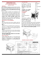
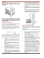
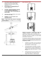
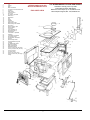
LEPRECHAUN 90 O.S.A
WOODBURNING STOVE
SAFETY NOTICE
Please read this entire manual before you install and use your new room heater. Failure to follow instructions
may result in property damage, bodily injury or even death.
This appliance is hot while in operation and retains its heat for a long period of time after use. Children,
aged or infirm persons should be supervised at all times and should not be allowed to touch the hot
working surfaces while in use or until the appliance has thoroughly cooled.
If this stove is not properly installed, a house fire may result. For your safety, follow the installation directions.
Contact local building or fire officials about restrictions and installation inspection requirements in your area.
The stove must be connected to a UL/ULC listed high temperature residential type H.T. and building heating
appliance chimney or an approved masonry chimney with flue liner.
INSTALLATION AND OPERATING INSTRUCTIONS
TOP FLUE EXIT
LEPRECHAUN 90 O.S.A.
WOODBURNING STOVE
INSTALLATION & OPERATING
INSTRUCTIONS
GENERAL
Fit part no. 14 over top
flue aperture in the hob
(Part No. 13) make sure
that part no. 14 is well
secured on a bed of fire
cement.
The complete installation must be done in accordance with current Standards and Local Codes. It
should be noted that the requirements and these
publications may be superseded during the life of
this manual.
Spacer
Heat Shield
ASSEMBLY OF OPTIONAL
CHIMNEY PIPE SHIELD
Spacer
HEAT SHIELD
ASSEMBLY
When installing, operating and maintaining your
Leprechaun 90 O.S.A. Stove respect basic standards of fire safety. Read these instructions carefully before commencing the installation. Failure to do
so may result in damage to persons and property.
Consult your local Municipal Office, Fire
Department, and your insurance representative to
determine what regulations are in force. Save these
instructions for future reference.
Top Exit:
Fit the head shield as
follows:
Screw the 4” 100mm x
1/4” 6mm tie bolts to the
back panel (item 11). Fit
the four 1” 25mm spacers
(item 31) over the tie bolts.
PRE-INSTALLATION ASSEMBLY
Step 1:
After removing the stove from its packing, open the
firedoor door and remove the contents from the fire
box.
Step 2:
Lay the stove on its side and fit the 4 legs (item 1)
with the 1/4” (6.4mm) hex sets screws provided,
tighten screws. Stand the stove upright, taking care
not to strain the leg bolts.
Step 3:
Install the Hot Plate (item 15) into the large opening
of the hob (item 13). Do not remove the Hot Plate
when the stove is lighting.
Fit the inner heat shield (item 28) with the blanking
plate on to the four tie bolts. Now fit the other four 1”
25mm spacers over the tie bolts and fit the outer heat
shield (item 30) complete with heat shield blanking
plate. Tighten the whole assembly together using the
four 1/4” 6mm nuts and washers provided.
THIS STOVE MAY BE CONNECTED TO EITHER A
TOP OR A REAR VENT.
REAR FLUE EXIT
Fit back sealing plate (Part no. 17) over the top flue
aperture in the hob (Part no. 13). Fit the flue spigot
to part no 11 where part no. 17 was, making sure
that part no. 17 and part no. 14 are well secured on
a bed of fire cement.
DAMPER HANDLE ASSEMBLY
Leprechaun 90 O.S.A.
Fionn 90 OSA
2
Rear Exit:
FLOOR PROTECTION
Fit the heat shield as follows:
When installing this heater on a combustible floor, a
floor protector, consisting of a layer of non-combustible material at least 3/8” (9.5mm) thick or 1/4”
(6mm) thick covered with 1/8” (3mm) sheet metal is
required to cover the area under the heater and to
extend to at least 18” (450mm) at the front and 8”
(200mm) to the sides and rear. This will provide protection from sparks and embers which may fall out
from the door when stoking or fuelling.
Screw the four 4” 100mm x 1/4” 6mm tie bolts to the
back panel (item 11). Fit the four 1” spacers (item
31) over the tie bolts. Fit the inner heat shield (item
28) without blanking plate onto the four tie bolts.
Now fit the other four 1” 25mm spacers over the tie
bolts and fit the outer heat shield (item 30) without
blanking plate. Tighten the whole assembly together using the four 1/4” 6mm nuts and washers provided.
(200mm)
(200mm)
(450mm)
(200mm)
(50mm)
(50mm)
LOCATION
There are several conditions to be considered when
selecting a location for your Leprechaun 90 O.S.A.
a.
b.
c.
d.
e.
3
Distance from a suitable chimney
(see chimneys).
Position in the area to be heated, central
locations are usually best.
Allowance for proper clearances to
combustibles.
Obstruction in the ceiling, upper floor or roof,
for example, ducting plumbing, electrical
fittings and wiring, overhead fixed
furnishings, etc.
For safety, and to avoid draughts, avoid
locations close to an exit.
WARNING
DO NOT OBSTRUCT FREE AIR SUPPLY TO THE
AIR INLET DUCT LOCATED AT THE BACK OF
THE STOVE.
g.
h.
l.
Air inlets traversing cavity walls should
include a continuous duct across the cavity.
The duct should be installed in such a man
ner as not to impair the weather resistance
of the cavity.
Joints between air vents and outside walls
should be sealed to prevent ingress of mois
ture.
This stove is listed for Mobile home installa
tion provided it is properly connected to an
outside air supply and a listed chimney with
a ceiling support and spark arrester.
DO NOT CONNECT TO OR USE IN CONJUNCTION WITH ANYAIR DISTRIBUTION DUCTWORK
UNLESS SPECIFICALLY APPROVED FOR SUCH
INSTALLATIONS.
OUTSIDE AIR CONNECTION
This stove may be connected direct to the outside of
the house for its combustion air supply.
MOBILE HOME INSTALLATION
Note: It is recommended to use the shortest
possible outside air supply ducts. Supply ducts with
long runs, multi bends and corners may reduce air
volume supply due to excessive drag.
In addition to standard installation instructions the
following requirements are mandatory for installation
in a Mobile Home.
CAUTION: Do not obstruct combustion air opening.
1.
2.
When connecting this stove to an outside air supply
the optional outside air kit must be used, which
includes a spigot, wire mesh, and fixing screws.
a.
b.
c.
d.
e.
f.
3.
4.
Fit the cast iron spigot into the air inlet (Part
No. 39).
Connect a 4” (100mm) stainless steel, gal
vanised ridge or flexible pipe to the air inlet
spigot.
Fit a 4” (100mm) stainless steel or galvanised sweep bend to the outside of the air
supply pipe.
Fit the stainless mesh to the downturn of the
bend terminus using the fixing screws sup
plied with the outside air kit.
Make sure that all joints are secured using
the fixing screws supplied with the outside
air kit.
The outside air terminus must be fitted with
the 1/4” (6mm) x 1/4” (6mm) stainless wire
mesh to prevent leaves and rodents entering
from the out side.
5.
6.
4
The stove must be permanently bolted to the
floor of the Mobile Home using the floor
screws provided.
The stove must have a permanent outside
air source for combustion.
The stove must be grounded to the steel
chassis of the Mobile Home.
A listed chimney system, roof thimble, spark
arrestor and roof flashing kit suitable for use
in Mobile Homes must be used.
If the chimney exits the Mobile Home at a
location other than through the roof, and
exits at a point 7ft. (2100mm) or less above
the ground level on which the Mobile Home
is positioned, a guard or method of enclosing
the chimney shall be fitted at the point of exit
for a height up to 7 ft.(2100mm).
The chimney shall be attached directly to the
room heater and shall extend at least 3 ft.
(910mm) above the part of the roof through
which it passes. The top of the chimney
should project at least 2 ft. (610mm) above
the highest elevation of any part of the
Mobile Home within 10 ft. (3050mm) of the
chimney.
7.
8.
WALL PROTECTORS
The chimney system shall comply with the
standard for Chimney’s Factory-Built
Residential Type and Building Heating
Appliances UL 103.
Any openings in a chimney guard if used
must not permit the entrance of a 3/4”
(19mm) diameter rod.
9.
CAUTION: THE STRUCTURAL INTEGRI
TY OF THE MOBILE HOME ROOF,
FLOOR, WALLS AND CEILING MUST BE
MAINTAINED.
10.
Check any other local building code as other
local codes may apply.
11.
WARNING: DO NOT INSTALL IN A
SLEEPING ROOM
Note: Listed factory built chimney connectors
including elbows are acceptable for use in Mobile
Home Installation’s.
Materials and products listed for the purpose of
reducing clearance to combustibles shall be
installed in accordance with the conditions of the
listing and the clearances may be reduced by the
percentage reduction as stated in the wall shield
manufacturer’s instructions.
For clearance reduction systems using an air space
between the combustible wall and the wall protector,
adequate air circulation shall be provided by one of
the following methods.
5
1.
Adequate air circulation may be provided by
leaving all edges of the wall protector open
with at least a 1” 25mm air gap.
2.
If the wall protector is mounted on a single
flat wall away from corners, adequate air circulation may be provided by leaving bottom
and top edges open with at least a 1” 25mm
air gap.
3.
Wall protectors that cover two walls in a corner shall be open at the bottom and top
edges with at least a 1” 25mm air gap.
4.
Chimney, installed in accordance with the manufacturers instructions or a lined masonry chimney
acceptable to the authority having jurisdiction.
All clearances shall be measured from the
outer surface of the combustible material to
the nearest point on the surface of the
Leprechaun 90 O.S.A., disregarding any
intervening protection applied to the combustible material.
CHIMNEY CONNECTORS
THE CHIMNEY CONNECTOR is a smokepipe used
to connect the Leprechaun 90 O.S.A. Stove to the
approved chimney described above. The CHIMNEY
CONNECTOR must be made of CORROSION
RESISTANT STEEL 24 gauge or heavier (“black” or
“blued”, or equivalent treated steel).
When using a manufactured wall shield system
observe local building codes and by-laws.
CHIMNEYS
Consult the LOCAL BUILDING CODE in all cases as
to the particular requirements concerning the
installation of SOLID FUEL TYPE ROOM
HEATERS. This Leprechaun 90 O.S.A. WOOD
BURNING STOVE is intended to be installed in
accordance with National Fire Protection
Associations Standard for Chimneys, Fireplaces
and Vents. NFPA 211-1977.
Be sure too fasten the chimney connectors together
and also to the flue outlet of the stove through the
holes provided. Use at least two screws for each
joint. Be sure the joints are tight and fully secured.
Chimney connectors shall not pass through an attic,
or roof space, closet or similar concealed space, or
a floor or ceiling. Where passage through a wall, or
partition of combustible construction is desired, the
installation shall conform to CAN/CSA -B 365,
Installation code for Solid Fuel Burning Appliances
and Equipment.
The chimney must have a CROSS SECTIONAL
AREA of at least 193.5 sq. cm. (30 sq. inches). It is
best connected to a chimney of the same size, as
connection to a larger size may result in somewhat
less draught.
The Leprechaun 90 O.S.A. is a Radiant Room
Heater and must be connected to a chimney of the
proper size and type, capable of providing an adequate continuous draught of 0.06wg minimum. It is
best to connect to a chimney of the same size as the
stove spigot. DO NOT CONNECT TO A CHIMNEY
SERVING ANOTHER APPLIANCE.
Connectors should maintain a pitch or rise of at least
1/4” (6mm) to the foot from the stove to the chimney.
It should be installed so as to avoid sharp turns or
other construction features that would create excessive resistance to the flow of flue gases. It should be
securely supported with joints fastened with sheetmetal screws, rivets, or other approved means. The
entire length of a connector should be readily accessible for inspection, cleaning and replacement.
Minimum chimney height is 14’ 10” (4.5m) from floor
on which stove is installed. An existing masonry
chimney should be inspected, and if necessary,
repaired by a competent mason or relined, using an
approved relining system. The stove must be
connected to a chimney with a minimum continuous
draught of 0.06”wg. Poor draught conditions will
result in poor performance.
The connector may pass through walls or partitions
constructed of combustible materials provided the
connector is either listed for wall pass-through or is
routed through a device listed for a wall passthrough and is installed in accordance with the conditions of the listing.
Any unexposed metal that is used as part of a wall
pass-through system and is exposed to flue gases
shall be constructed of stainless steel or other equivalent material that will resist corrosion, softening or
cracking from flue gas at temperatures up to 982 oC.
Note: Connection to type “B” Gas Vents, approved
for connection to a certain gas burning appliance will
only result in a fire.
CHIMNEY TYPES - USA ONLY
CONNECTING TO MASONRY CHIMNEY
The stove must be connected to a UL 103 Listed
residential Type HT and Building Heating, Appliance
chimney installed in accordance with the manufacturers instructions or a masonry chimney
constructed in accordance with NFPA 211 Chimney
vents and Solid Fuel Burning Appliances.
The connector to a masonry chimney must extend
through the wall to the liner face or liner but not
beyond, and must be firmly cemented to masonry.
The connector may pass through walls or partitions
constructed of combustible material to a masonry
chimney provided the connector system selected is
installed in accordance with the proper clearances
and conditions (See figures A,B,C,D page 8 & 9).
CHIMNEY TYPES - CANADA ONLY
The stove must be connected to an Underwriters
Laboratories of Canada labelled Factory Built 650oC
6
1.
2.
3.
4.
5.
6.
7.
8.
9.
10.
11.
12.
13.
14.
15.
16.
17.
18.
19.
20.
21.
22.
23.
24.
25.
26.
27.
28.
29.
30.
31.
32.
33.
34.
35.
36.
37.
38.
39.
40.
41.
42.
43.
44.
Leg
Ashtray
Base
Base Heat Shield
Combustion Chamber Base Plate
Fire Door
Side Panels
Inside Fire Door
Door Latch
Top Side of Top Baffle
Back Panel
Back Baffle
Hob
Spigot
Hotplate
Front Frame
Back Sealing Plate
Back Sealing Plate Gasket
Door Catch
Window Sealing Tape
Window Glass
Fire Fence
Front Side Brick (2)
Rear Side Brick (2)
Bottom Bricks
Lower Side of Top Baffle
Air Baffle
Inside Back Heat Shield
Door Sealing Rope
Outside Back Heat Shield
Spacers
Optional Pipe Shield
Heat Shield Blanking Plate
Tie Bolts
Top Baffle Plate Gasket
Back Panel Gasket
Side Panel Gaskets
Back Baffle Gasket
Primary & Secondary Air Spigot
Primary and Secondary Air Flap
Cast Iron Spacer
Connecting Rod
Primary Air Control Lever
Primary & Secondary Air Spigot
Flange
LEPRECHAUN 90 O.S.A.
WOOD BURNING STOVE
EXPLODED VIEW
U.S. ENVIRONMENTAL PROTECTION AGENCY
Certified to Comply with July 1990
Particulate Emission Standards
Maximum Heat Output up to 33,000 BTU’s/hr
Heat Output Range 9,000 - 26,700 BTU’s/hr
44
7
THIMBLES
2.
Thimbles for chimneys or vent connectors should be
of fire clay (ASTM C 315, specifications for Clay
Flue Linings), galvanised steel of minimum thickness of 24 gauge, or material of equivalent durability. Thimbles should be installed without damage at
the liner. The thimble should extend through the
wall to, but not beyond, the inner face of the liner
and should be firmly cemented to masonry.
Thimbles should be located to provide adequate
pitch or rise of chimney or vent connectors and,
where the ceiling above the appliance is constructed
of combustible material, the location of the thimble
should provide minimum clearance required for the
connector as specified in section under Minimum
Clearances.
Minimum chimney clearance from masonry to
sheet steel supports and combustibles 2” (50mm)
(230mm)
Masonry
chimney
constructed to
NFPA 211
Factory built chimney length
Air space 9” (230mm) minimum
3.
CHIMNEY CONNECTOR SYSTEMS, THIMBLES,
AND CLEARANCES FROM COMBUSTIBLE
WALLS
Minimum 3 1/2” (90mm) thick brick masonry
wall framed into combustible wall with a min.
of 12” (305mm) brick separation from clay
liner to combustibles. Fire clay liner (ASTM
C315 or equivalent) min. 5/8” (16mm) wall
thickness, should run from outer surface of
brick wall to, but not beyond, the inner surface of chimney flue liner and should be
firmly cemented in place.
FIGURE B
Sheet steel chimney connector, min. 24
gauge in thickness, with a ventilated thimble,
min. 24 gauge in thickness, having two 1”
(25mm) air channels, separated from combustibles by a min. of 6” (150mm) of glass
fibre insulation. Opening should be covered
and thimble supported with a sheet steel
support, min. 24 gauge in thickness.
Supports should be securely fastened to
wall surfaces on all sides and should be
sized to fit and hold chimney section.
Fasteners used to secure chimney sections
should not penetrate chimney flue liner.
Minimum chimney clearance to sheet steel
supports and combustibles 2” (50mm)
Two air channels
each 1” (25mm)
Chimney
connector
Minimum 6” (150mm)
glass fibre insulation
Minimum chimney clearance to
brick and combustibles 2” (50mm)
Sheet steel
supports
Minimum clearance 12” (300mm) of brick
Fire Clay Liner
4.
Chimney connector
Minimum 12” (300mm)
to combustibles
FIGURE A
Non-soluable
refractory
cement
Chimney
length flush
with inside
of flue
Insulation material used as part of wall pass-through
system should be of non-combustible material and
should have a thermal conductivity of 1.0 Btu. in./ft.F
(4.88 kg.cal/hr.m.c) or less. All clearances and thicknesses are minimums; larger clearances and thicknesses are acceptable. Any material used to close
up the opening for the connector should be of noncombustible material. A connector to a masonry
chimney, except for System 2 (under heading
Chimney Connector System, Thimbles and
Clearances), shall extend to piece through the wall
pass-through system and the chimney wall to the
inner face of the flue liner, but not beyond.
1.
Solid insulated listed factory-built chimney
length of the same inside diameter as the
chimney connector and having 1” (25mm) or
more of insulation with a min. 9” (230mm) air
space between the outer wall of the chimney
length and combustibles. The inner end of
the chimney length shall be flush with the
inside of the masonry chimney flue and shall
be sealed to the flue and to the brick masonry penetration with non water-soluble refractory cement. Supports should be securely
fastened to wall supports and the chimney
length shall not penetrate the chimney liner.
Masonry
Chimney
constructed to
NFPA 211
8
Two ventilated air
channels each 1”
(25mm) constructed
of sheet steel
FIGURE C
Solid insulated listed factory-built chimney
length with an inside diameter 2” (50mm)
larger than the chimney connector and having 1” (25mm) or more of insulation, serving
as a pass-through for a single wall sheet
steel chimney connector of min. 24 gauge
thickness, with a min. 2” (50mm) air space
between the outer wall of chimney section
and shall be 12” (305mm). Chimney
section concentric with and spaced 1”
(25mm) away from connector by means of
sheet steel support plates on both ends of
chimney section. Opening shall be covered
and chimney section supported on both
sides with sheet steel supports of min. 24
gauge thickness.
other listed chimney connector from the appliances
flue outlet up through the fireplace damper and
smoke chamber, terminating at the first flue tile, or
by installing a stainless steel or other listed relining
system from the flue outlet up the entire length of the
chimney, where necessary.
Supports should be securely fastened to wall surfaces on all sides and shall be sized to fit and hold
chimney section. Fasteners used to secure chimney
sections should not penetrate chimney flue liner.
Minimum chimney clearance
to sheet steel supports and
combustibles 2” (50mm)
Chimney
Section
Minimum clearances 2” (50mm)
1” (25mm) air
space to
chimney length
Air Space 2”
(50mm)
In Canada when connecting to a masonry fire place
the steel chimney connector must terminate at the
top of the chimney or flue liner.
Chimney length
FIGURE D
MASONRY FIRE PLACE
The stove maybe installed on the hearth extension
of a masonry fireplace. In Canada a continuous
liner must be provided from the flue collar of the
stove to the top of the chimney. In the USA a continuous chimney flue is required. A minimum clearance of 25” (635mm) is required to combustible
mantle and a minimum clearance of 14” (355mm) to
side trim, which extends less than 2” (50mm) from
the face of the fireplace. (See Section under
Minimum Clearances to Combustibles).
Flue Liner
Stainless Steel
Chimney Connector
Insulated non-combustible
throat seal
Before the installation the entire fireplace system
should be inspected for condition and code compliance prior to connecting to the fireplace chimney.
Older fireplaces and chimneys may not have been
constructed to current-day codes.
VENTILATION & COMBUSTION AIR
REQUIREMENTS
The fireplace and chimney should be in, or brought
up to, acceptable conditions and proper clearances
should be met before connecting to the fireplace
chimney.
Ventilation and an adequate air supply is necessary
to supply combustion air to the appliance. Refer to
your local Authority for current requirements in your
jurisdiction.
The size of the flue must be considered. If the fireplace chimney is too large, a relining system may be
installed using an approved relining system.
Outside combustion air may be required if:
The solid-fuel-fired appliance does not draw
steadily, smoke rollout occurs, fuels burns
poorly, or back drafts occur whether or not
there is combustion present.
Connection to a masonry chimney may be done by
breaching into the chimney from the front of the fireplace, no less than 8” (200mm) above the bottom of
the first flue tile, by installing a stainless steel or
9
2.
3.
4.
5.
6.
Existing fuel-fired equipment in the house,
such as fireplaces or other heating appliances, smell, do not operate properly, suffer
smoke roll-out when opened, or back-draft
whether or not there is combustion present.
Opening a window slightly on a calm
(windless) day alleviates any of the above
symptoms.
The house is equipped with a well-sealed
vapour barrier and tight fitting windows
and/or has any powered devices that
exhaust house air. (e.g. Extraction Hood or
Tumble Dryers etc..)
There is excessive condensation on windows in the winter.
A ventilation system is installed in the house.
2.
3.
If these or other indications suggest that infiltration
air is inadequate, additional combustion air should
be provided from the outdoors. Outside combustion
air can be provided to the appliance by the following
means:
1.
2.
3.
4.
5.
Direct connection: Refer to O.S.A. Hook-up
in this manual.
Indirect method: for an appliance not
certified for direct connection of outside
combustion air, the outside air is ducted to a
point no closer than (12”) 300mm from the
appliance, to void affecting the performance
of the appliance.
A mechanical ventilation system: if the
house has a ventilation system (air change
or heat recovery):
a. The ventilation system may be able
to provide sufficient combustion make-up
air for the solid-fuel-fired appliance.
b. The householder should be informed that
the ventilation system might need to be
re-balanced by a ventilation technician
after installation of the appliance.
6.
7.
SPILLAGE TEST
1.
2.
3.
4.
Light/burn appliance under normal conditions in accordance with this installation
manual.
Close all doors and windows.
Operate all appliances requiring a full rate
(eg. extraction hoods, tumble dryers etc).
Check for spillage.
The chimney connector and chimney should be
inspected at least twice monthly during the heating
season to determine if a creosote build-up has
occurred. If creosote has accumulated it should be
removed to reduce the risk of a chimney fire.
LIGHTING
1.
has caught fire adjust the primary air settings
to suit the heat requirements.
The logs will burn slowly towards the rear of
the fire chamber and the rate of burning is
adjustable at all times by means of the primary air settings. The more air (wider open
ing) the faster the burning. Do not overfire
the stove. If the stove or chimney connector
glows, you are overfiring the stove.
When the fire is reduced to embers, open the
door and carefully rake the embers towards
the front of the fire chamber and reload with
logs. After fuelling the stove hold the fire
door (part number 6) cracked open for 3-5
minutes to enhance combustion, close the
fire door (item 6) and adjust the Primary air
settings to give the required heat output.
Keep all combustible materials at least three
feet away from the stove and connector
pipes. Never dry clothing on or over the
stove or within three feet of it.
Use the main top of the stove for boiling, simmering etc. You will soon learn the best
ways and means of using the stove in order
to attain maximum efficiency.
Disposal of Ashes - Ashes should be
placed in a metal container with a tight fitting
lid. The closed container of ashes should be
placed on a non-combustible floor or on the
ground, well away from all combustible
materials, pending final disposal. If the
ashes are disposed of by burial in soil or otherwise locally dispersed, there should be
retained in the closed container until all cinders have thoroughly cooled.
Creosote - Formation and Need for
Removal when wood is burned slowly, it pro
duces tar and other organic vapours, which
combine with expelled moisture to form creosote. The creosote vapours condense in
the relatively cool chimney flue of a slowburning fire. As a result, creosote residue
accumulates on the flue lining. When ignited
this creosote makes an extremely hot fire.
Inspect the chimney connector frequently. Tap the
connector with your finger when the pipe is cool. If
you hear a dull echo, the pipe may need cleaning.
Disassemble the chimney connector and clean the
sections. Replace corroded pipe sections. The fitting of a slip-joint in the stove pipe makes the dismantling easy for cleaning and inspection of chimney and stove.
Lay a few crumpled sheets of paper on the
hearth, then a few small sticks or kindling to
get the fire started. Open the fire door and
light paper. Close the door and open the primary air control ALL THE WAY. The fire will
catch the kindling quickly, after which a full
size log may be placed on top. After the log
10
MAINTENANCE
When inspecting a masonry chimney, start at the
cleanout door, normally found in the basement, at
the base of the chimney, or on the outside. If your
chimney does not have a clean-out door it must be
inspected and cleaned by removing stove from
chimney.
WARNING: DO NOT CLEAN STOVE WHEN HOT.
GLASS
1.
How to Clean:
The glass will clean itself when there is sufficient
heat generated by burning fuel. The Air Way system
provides pre-heated warm air which keeps the glass
clean.
IMPORTANT: NEVER LEAVE THE STOVE
UNATTENDED WHEN THE FIREDOOR IS IN THE
CRACKED OPEN POSITION.
UNDER NO CIRCUMSTANCES SHOULD ANY
FLAMMABLE LIQUIDS, KEROSENE, GAS OIL
LINE, NAPHTHA, ENGINE OIL, LIGHTER FLUID
OR CHARCOAL - STARTERS BE USED TO
LIGHT OR “FRESHEN UP” THE FIRE. NEVER
USE MANUFACTURED LOGS. KEEP ALL SUCH
LIQUIDS WELL AWAY FROM STOVE WHILE IN
USE
WARNING: DO NOT OPERATE THE STOVE
WITH BROKEN GLASS.
2.
(a)
How to Replace:
Open the door (item 6) and remove the 4
1/4” (6.4mm) counter sunk screws from the
inside Fire Door (item 8) and lift it away.
Remove the broken glass and gasket, take
the replacement glass and fit gasket.
DO NOT USE GRATE OR ELEVATE FIRE - BUILD
WOOD FIRE DIRECTLY ON HEARTH.
(b)
DO NOT BURN GARBAGE/RUBBISH IN THIS
UNIT.
NOTE: If the gasket is damaged, use a new gasket
PRIMARY AIR SETTINGS
DOOR ASSEMBLY
MAXIMUM - Pull control lever (item 43) all the way
towards the front.
LOW (MIN) - Push the control lever (item 43) all the
way towards the back.
(c)
(d)
Replace the glass and fit the Inside Fire Door
(item 8). Tighten the 4 fixing screws.
Close the door to make sure that it is sealing
properly against the Front Frame (item 16).
VITREOUS ENAMEL CLEANING
General cleaning must be carried out when the
stove is cool.
FUNCTION DIAGRAM OF LEPRECHAUN 90
O.S.A. WOOD BURNING STOVE
If this stove is finished in a high gloss vitreous
enamel, to keep the enamel in the best condition
observe the following tips:
1.
2.
3.
11
Wipe over daily with a soapy damp cloth,
followed by a polish with a clean dry duster.
For stubborn deposits a soap impregnated
pad can be carefully used on the vitreous
enamel.
DO NOT USE ABRASIVE PADS OR OVEN
CLEANSERS CONTAINING CITRIC ACID
ON ENAMELLED SURFACES. ENSURE
THAT THE CLEANSER MANUFACTUR
ERS INSTRUCTIONS ARE ADHERED TO.
WARNING: USE ONLY CERAMIC GLASS 5mm
THICK. ABUSE SUCH AS STRIKING, SLAMMING
AND USE OF SUBSTITUTE MATERIALS
SHOULD BE AVOIDED.
3.
4.
IN THE EVENT OF A CHIMNEY FIRE
FIRE SAFETY
(a)
(b)
(c)
(d)
To provide reasonable fire safety, the following
should be given serious consideration:
1.
2.
A practiced evacuation plan.
A plan to deal with a chimney fire as follows:
The installation of smoke detectors.
A conveniently located Class A fire extinguisher to contend with small fires resulting
from burning embers.
Notify the fire department.
Prepare occupants for immediate evacuation
Close all openings into the stove.
While awaiting fire department watch for ignition to adjacent combustibles from over
heated stove pipe or hot embers or sparks
from the chimney.
LEPRECHAUN 90 O.S.A.
MINIMUM CLEARANCES TO COMBUSTIBLE MATERIALS:
SIDE WALL TO STOVE . . . . . . . . . . . . . . . . . . . . . . . . . . . . . . .20 INCHES - 510 mm
BACK WALL TO CHIMNEY CONNECTOR .................................18 INCHES - 460mm
BACK WALL TO STOVE TOP & REAR EXIT ..............................141/2” INCHES - 370mm
CEILING TO HORIZONTAL CONNECTOR .................................18 INCHES - 460mm
CORNER. .....................................................................................13 INCHES - 330mm
MANTLE CLEARANCE . . . . . . . . . . . . . . . . . . . . . . . . . . . . . . . .25 INCHES - 635mm
SIDE TRIM ...................................................................................14 INCHES - 355mm
FLOOR PROTECTION
When installing this heater on a combustible floor, a floor protector consisting of a layer of non-combustible
material at least 3/8” thick or 1/4” thick covered with 1/8” sheet of metal is required to cover the area under the
heater to extend at least 18” at the front and 8” to the sides and back of stove. This will provide protection from
sparks and ember which may fall out from the door when stoking or refuelling.
Waterford Stanley Ltd.,
Bilberry, Waterford, Ireland.
Tel: 051-302300
Fax: 051-302375
12
Rev: 001: DP030814


![installation & directions for use installation & mode d`emploi [ en ] [ fr ]](http://vs1.manualzilla.com/store/data/006516414_1-826c39eefa343060f035675bc430e123-150x150.png)