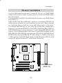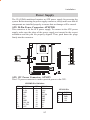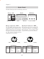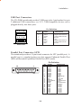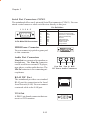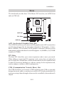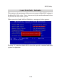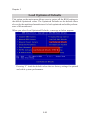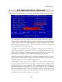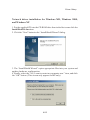
1
VIA Mainboard
User’s Manual
VIA P4MA - L
VIA P4MA - VSL
P4MA-L does NOT include Voice Post/Smart Card/
Memory Stick/Secure Digital functions as described
in this User’s Manual. This applies to all related pin
headers, BIOS settings, and software applications.
Voice Post and Smart media functions are only
supported by P4MA-VSL.
Version 1.0 - March 29th, 2002
P/N 99-51-010211
i
Copyright
Copyright by VIA Technologies Inc. (“VIA”). No part of this manual may be
reproduced or transmitted in any form without express written authorization
from VIA.
Trademarks
All trademarks are the property of their respective holders.
Data protection
All data should be backed-up prior to the installation of any drive unit or
storage peripheral. VIA will not be responsible for any loss of data resulting
from the use, disuse or misuse of this or any other VIA product.
No Warranty
VIA has made every effort to ensure the accuracy of the content of this
manual. However, it is possible that it may contain technical inaccuracies or
typographical or other errors. VIA will assume no liability for any inaccuracy
found in this publication, nor for damages, direct, indirect, incidental,
consequential or otherwise, that may result from such an inaccuracy, including
without limitation loss of data or profits.
VIA provides this manual “as is”, and does not issue a warranty of any kind,
express or implied, including without limitation implied warranties of
merchantability or fitness for a particular purpose.
The information provided in this manual is subject to change without notice.
VIA reserves the right to alter product designs, layouts or drivers without
notification.
ii
FCC-B Radio Frequency Interference Statement
This equipment has been tested and found to comply with the limits for a class
B digital device, pursuant to part 15 of the FCC rules. These limits are designed
to provide reasonable protection against harmful interference when the equipment is operated in a commercial environment. This equipment generates, uses
and can radiate radio frequency energy and, if not installed and used in accordance with the instruction manual, may cause harmful interference to radio
communications. Operation of this equipment in a residential area is likely to
cause harmful interference, in which case the user will be required to correct
the interference at his own expense.
Notice 1
The changes or modifications not expressly approved by the party responsible for compliance could void the user’s authority to operate the equipment.
Notice 2
Shielded interface cables and A.C. power cord, if any, must be used in order to
comply with the emission limits.
iii
TRADEMARKS
All trademarks used in this manual are the property of their respective owners.
Intel and Pentium are registered trademarks of Intel Corporation.
PS/2 and OS/2 are registered trademarks of IBM Corporation.
Windows 95/98/98SE/ME/2000/XP and Windows NT are registered trademarks
of Microsoft.
Netware is a registered trademark of Novell.
Award is a registered trademark of Award Software Inc.
NOTE
1.
2.
3.
4.
5.
Always read the safety instructions carefully.
Keep this User’s Manual for future reference.
Keep this equipment away from humidity.
Lay this equipment on a reliable flat surface before setting it up.
The openings on the enclosure are for air convection and protect the
equipment from overheating. DO NOT COVER THE OPENINGS.
6. Make sure the voltage of the power source and adjust properly 110/220V
before connecting the equipment to the power inlet.
7. Place the power cord such a way that people cannot step on it. Do not
place anything over the power cord.
8. Always Unplug the Power Cord before inserting any add-on card or module.
9. All cautions and warnings on the equipment should be noted.
10. Never pour any liquid into the opening. Doing so could cause damage or
electrical shock.
11. If any of the following situations arises, get the equipment checked by a
service personnel:
* The power cord or plug is damaged
* Liquid has penetrated into the equipment
* The equipment has been exposed to moisture
* The equipment does not work well or does not work according to
the User’s Manual.
* The equipment has dropped or damaged
* The equipment has been visably damaged
12. DO NOT LEAVE THIS EQUIPMENT IN AN ENVIRONMENT UNCONDITIONED, STORAGE TEMPERATURE ABOVE 600 C (1400F), IT MAY
DAMAGE THE EQUIPMENT.
iv
Box Contents
• 1 x VIA Mainboard
• 1 x User’s manual
• 1 x Quick Installation Guide
• 1 x Floppy ribbon cable
• 1 x ATA-66/100/133 IDE ribbon cable
• 1 x 2 Port USB 1.1 Module
• 1 x Driver Utilities CD
v
Contents
Specifications ........................................................ 1-1
Mainboard Specifications .................................................. 1-2
Mainboard Layout ............................................................ 1-4
Connectors Guide ............................................................. 1-5
Installation ............................................................ 2-1
CPU Installation ................................................................ 2-2
CPU Installation ............................................................... 2-2
CPU Core Speed .............................................................. 2-3
CPU Fan Installation ........................................................ 2-3
Memory Installation........................................................... 2-5
DDR Module Installation .................................................. 2-6
Power Supply ................................................................... 2-7
ATX 20-Pin Power Connector: ATXPWR ....................... 2-7
ATX 12V Power Connector: AUX12V............................ 2-7
Back Panel ....................................................................... 2-8
Mouse Connector: JMS1 .................................................. 2-8
Keyboard Connector: JKB1 ............................................. 2-8
USB Port Connectors....................................................... 2-9
Parallel Port Connector: LPT1 ......................................... 2-9
Serial Port Connector: COM 1 ....................................... 2-10
MIDI/Game Connector .................................................. 2-10
Audio Port Connectors ................................................... 2-10
RJ45 NIC Port ............................................................... 2-10
VGA Out ........................................................................ 2-10
Connectors ..................................................................... 2-11
Floppy Disk Drive Connector: FDD ................................ 2-11
IrDA Infrared Module Connector: IR ............................. 2-11
Consumer IR Connector: CIR ........................................ 2-12
CD-In Connector: CD_IN ............................................. 2-12
Hard Disk Connectors: IDE1 & IDE2 ........................... 2-13
Fan Power Connectors: CPU/SYS FAN ....................... 2-14
Case Connectors: F_PANEL/F_PANEL2 .................... 2-14
vi
Digital Audio Connector: SPDIF ....................................
PC Smart Card Reader: SCR.........................................
USB pin-header: USB3/4 ...............................................
Wake-On LAN Connector: WOL ..................................
Wake-On Ring Connector: WOR...................................
Secure Digital and Memory Stick Connectors: SD/MS .
2-16
2-16
2-17
2-17
2-18
2-18
Jumpers .......................................................................... 2-19
Clear CMOS Jumper: CLEAR_CMOS ......................... 2-19
Audio Codec Auto Detect Jumper: OB_CODEC ......... 2-20
Slots ............................................................................... 2-21
AGP (Accelerated Graphics Port) Slot ..........................
PCI Slots ........................................................................
CNR (Communication Network Riser) Slot ...................
PCI Interrupt Request Routing .......................................
2-21
2-21
2-21
2-22
BIOS Setup ........................................................... 3-1
Entering Setup................................................................... 3-2
Control Keys .................................................................... 3-2
Getting Help...................................................................... 3-3
The Main Menu ................................................................ 3-4
Standard CMOS Features ................................................ 3-6
Advanced BIOS Features ................................................. 3-8
Advanced Chipset Features............................................. 3-11
Integrated Peripherals...................................................... 3-13
Power Management Setup .............................................. 3-18
PNP/PCI Configurations ................................................. 3-23
PC Health Status............................................................. 3-25
Frequency/Voltage Control .............................................. 3-26
Load Fail-Safe Defaults................................................... 3-29
Load Optimized Defaults ................................................. 3-30
Set Supervisor/User Password ........................................ 3-31
Save & Exit Setup........................................................... 3-33
Exit Without Saving ......................................................... 3-34
vii
Software Setup ..................................................... 4-1
VIA ProSavage8 P4M266 Chipset Drivers ....................... 4-2
VIA ProSavage8 P4M266 VGA Driver .......................... 4-12
VIA Audio Driver........................................................... 4-18
Realtek Network Driver .................................................. 4-19
Winbond Smart@IO Drivers ........................................... 4-26
Winbond Voice Editor Utility ........................................... 4-28
viii
Specifications
1
Specifications
The VIA P4MA mainboard is based around the
VIA ProSavageDDR P4M266 chipset, which brings
support for high-performance DDR266 SDRAM to the
Intel® Pentium® 4 platform. It is a high performance,
cost-effective and energy efficient SMA chipset for
the desktop PC. VIA’s advanced V-Link controller
brings optimal system efficiency by effectively doubling bandwidth between the chipset’s north and south
bridges. P4M266 integrates S3 Graphics’ 128-bit
ProSavage8 graphics accelerator into a single chip,
providing ideal solution for the consumer and entry
level professionals.
This chapter includes the following sections:
Mainboard Specifications
Mainboard Layout
Connectors Guide
1-1
1-2
1-4
1-5
Chapter 1
Mainboard Specifications
CPU
• Supports Intel® Pentium® 4/Northwood processors in the 478 pin package
• Supports 1.6GHz, 1.7GHz, 1.8GHz, 1.9GHz, 2GHz, 2.2GHz and upwards
Chipset
• VIA P4M266/VT8233A chipset
- Supports Intel® Pentium® 4 processors with 400MHz (100MHz QDR) CPU
Front Side Bus (FSB)
- Integrated Savage8 AGP Graphics
- External 4x AGP Bus
- High Bandwidth V-Link Client controller
- Integrated Hardware Sound Blaster/Direct Sound AC’97 audio
- Ultra DMA 66/100/133 master mode PCI EIDE controller
- ACPI 1.0B and APM 1.2 compliant
Main Memory
• 2 x 184-pin DDR DIMM slots
• Supports up to 2GB of DDR SDRAM (PC2100/PC1600)
• Supports 2.5v DDR266 SDRAM
Slots
• 1 x AGP (Accelerated Graphics Port) 4X slot
• 3 x PCI 2.2 32-bit PCI bus slots (supports 3.3v/5v PCI bus interface)
• 1 x CNR (Communication Network Riser) slot
Onboard IDE
• Integrated IDE controller provides IDE HDD/CD-ROM with PIO, Bus Master and Ultra DMA 66/100/133 operation modes
• Can connect up to four IDE devices
Onboard Peripherals
• 1 x floppy port supports 1 x FDD
• 1 x serial ports (COM 1)
1-2
Specifications
•
•
•
•
•
1 x DB-15 VGA out port
1 x SPP/EPP/ECP mode compliant parallel port.
2 x USB 1.1 ports (plus 1 pin-header for up to 2 additional connections)
1 x MIDI/Game port
1 x RJ-45 NIC port
Audio
• S/W VIA VT1612A AC'97 Codec
BIOS
• Award Plug & Play BIOS
• Desktop Management Interface (DMI) function which records your
mainboard specifications
Dimension
• MicroATX Form Factor
• 24.5cm x 24cm
Mounting
• 6 mounting holes
1-3
Chapter 1
Mainboard Layout
Top: Mouse
Bottom: Keyboard
CPUFAN
ATXPWR
Top:
Parallel port
Bottom:
COM 1/VGA out
FDD
Socket 478
Top: RJ45
Bottom: USB ports
IDE 2
PCI Slot 1
SD
MS
PCI Slot 2
SPDIF
PCI Slot 3
CIR
BIOS
IDE 1
AGP Slot
CD_IN
Top: Game port
Bottom:
Line-Out
Line-In
Mic
M
AUX12V
IR
SCR
USB 3/4
CNR
OB_Codec
WOR
WOL
CLEAR_CMOS
SYSFAN
F_PANEL2
VIA P4MA - L & VIA P4MA - VSL Mainboard
1-4
F_PANEL
Specifications
Connectors Guide
Connectors
ATXPWR
ATX12V
Function
ATX 20-pin power connector
ATX 12V power connector
Reference
see p. 2-7
see p. 2-7
JMS1
Mouse connector
see p. 2-8
JKB1
USB Port Connectors
Keyboard connector
Connecting to USB devices
see p. 2-8
see p. 2-9
LPT1
COM 1
Parallel port connector
Serial port connector
see p. 2-9
see p. 2-10
MIDI/Game Connector
Connecting to joystick or game pad
see p. 2-10
Audio Port Connectors
Line-Out/Line-In/Mic-In
see p. 2-10
RJ45 NIC Port
VGA Out
LAN port
VGA connector
see p. 2-10
see p. 2-10
FDD
Floppy disk drive connector
see p. 2-11
IR
CIR
CD_IN
IrDA Infrared Module connector
Consumer IR Module connector
CD-In connector
see p. 2-11
see p.2-12
see p. 2-12
IDE 1 & IDE 2
CPUFAN/SYSFAN
Hard disk connectors
Fan Power connectors
see p. 2-13
see p. 2-14
F_PANEL/F_PANEL2
Case connectors
see p. 2-14
SPDIF
SCR
Digital audio connector
PC Smart Card Reader connector
see p. 2-16
see p. 2-16
USB 3/4
WOL
USB pin-header
Wake-On LAN connector
see p. 2-17
see p. 2-17
WOR
SD/MS
Wake-On Ring connector
Secure Digital/Memory Stick
see p. 2-18
see p. 2-18
CLEAR_CMOS
OB_CODEC
AGP Slot
PCI Slots
CNR Slot
Clear CMOS jumper
Audio Codec Auto Detect jumper
Connecting to AGP card
Connecting to PCI cards
Connecting to CNR card
see p. 2-19
see p. 2-20
see p. 2-21
see p. 2-21
see p. 2-21
1-5
Installation
2
Installation
This chapter provides you with information
about hardware setup procedures. While installing
the mainboard, carefully hold the components and
closely follow the installation procedures. Some
components may be damaged if they are installed
incorrectly.
It is recommended to use a grounded wrist
strap before handling computer components. Static
electricity can damage some components.
This chapter contains the following sections:
CPU Installation
Memory Installation
Power Supply
Back Panel
Connectors
Jumpers
Slots
2-1
2-2
2-5
2-7
2-8
2-11
2-19
2-21
Chapter 2
CPU Installation
The VIA P4MA mainboard supports the Intel® Pentium® 4 processor in the 478
pin package (PGA478). When installing the CPU, ensure the CPU has a largesize heatsink and a cooling fan attached on the top to prevent overheating. If
the heatsink and cooling fan are not included with the CPU, contact your
dealer to purchase and install them before turning on the computer.
CPU Installation
1. Pull the lever sideways away
from the socket. Then raise the
lever up to a 90-degree angle.
2. Look for the dot/cut edge. The
dot/cut edge should point towards the lever pivot. The
CPU will only fit in the correct
orientation.
3. Hold the CPU down firmly,
then close the lever shut to
complete the installation.
WARNING!
Overheating will cause serious damage to the CPU
and system. Ensure the cooling fan and heatsink work
properly to protect the CPU from overheating.
2-2
Installation
CPU Core Speed
If
then
CPU Clock
=
Core/Bus ratio =
CPU core speed =
=
=
100MHz
18
CPU Clock x Core/Bus ratio
100MHz x 18
1.8GHz
Overclocking
This mainboard is designed to support overclocking. However,
WARNING! please make sure your components are able to tolerate such abnor-
mal settings, before overclocking. Any attempt to operate beyond
product specifications is not recommended. We do not guarantee the
damages or risks caused by inadequate operation or operation beyond
CPU Fan Installation
As processor technology pushes to faster speeds and higher performance,
thermal management becomes increasingly important. To dissipate heat, you
MUST attach the CPU cooling fan and heatsink on top of the CPU. Follow the
instructions below to install the Heatsink/Fan:
1. Locate the CPU and its retention
mechanism on the mainboard.
2. Position the heatsink and fan onto the
retention mechanism.
Retention mechanism
2-3
Chapter 2
3. Mount the fan on top of the heatsink. Press down the fan firmly until its four clips
become wedged in the holes of the retention mechanism.
4. Press the two levers down to secure the fan. Each lever can be pressed down in only
ONE direction.
5. Connect the fan power cable from the mounted fan to the 3-pin fan power connector
on the mainboard.
2-4
Installation
Memory Installation
The VIA P4MA mainboard provides 2 sockets for 184-pin, 2.5V DDR DIMM
modules with 4 memory banks. To operate properly, at least one DIMM module
must be installed.
You can install PC1600/PC2100 DDR SDRAM modules on the DDR DIMM
slots (DDR 1~2).
DDR (Double Data Rate) SDRAM is similar to conventional SDRAM, but
doubles the rate of transfer by transfering data twice per cycle. This is achieved
by transfering data on both the rising and falling edges of the clock.
Conventional SDRAM only uses the rising edge of the clock to transfer data.
Therefore, conventional SDRAM is called SDR (Single Data Rate) SDRAM.
DDR SDRAM uses 2.5 volts as opposed to 3.3 volts used in SDR SDRAM, and
requires 184-pin DIMM modules rather than 168-pin DIMM modules used by
SDR SDRAM. DDR SDRAM is also known as SDRAM-II, DDR DRAM and
DSDRAM (Double-Speed DRAM). PC2100 running at 133MHz will produce
2.1GB/s memory bandwidth. High memory bandwidth makes DDR an ideal
solution for high performance PC, workstations and servers.
M
Socket 478
DDR DIMM Slots
(DDR 1~2)
2-5
Chapter 2
DDR Module Installation
You can install either single sided or double sided 184-pin DDR DIMM modules
into the DDR DIMM slot, depending on your requirements. Differing from
SDR DIMM, DDR DIMM modules have only one notch on the center of the
module. The number of pins on either side of the breaks are also different. The
memory modules will only fit if placed in the correct orientation.
You can install DDR SDRAM modules in any of the following combinations:
Slot
M emory M odule
Total M emory
Slot 1
(Bank 0 & Bank 1)
64M B, 128MB,
256M B, 512M B, 1GB
64M B~1GB
Slot 2
(Bank 2 & Bank 3)
64M B, 128MB,
256M B, 512M B, 1GB
64M B~1GB
M aximum System M emory Supported
64M B~2GB
1. The DDR DIMM module has only one notch on the center.
Notch
2. Insert the DDR module vertically into the DDR DIMM slot. Make sure the
notch is correctly aligned.
3. The plastic clips at sides of the DIMM slot will automatically close shut.
2-6
Installation
Power Supply
The VIA P4MA mainboard requires an ATX power supply for powering the
system. Before inserting the power supply connector, always make sure that all
components are installed properly to ensure that no damage will be caused.
ATX 20-Pin Power Connector: ATXPWR
This connector is for the ATX power supply. To connect to the ATX power
supply, make sure the plugs of the power supply are inserted in the correct
orientation and the pins are properly aligned. Then, push down the plugs
firmly into the connector.
Socket 478
2
4
1
20
10
M
1
3
11
AUX12V
ATXPWR
ATX 12V Power Connector: ATX12V
This 12V power connector is used to provide power to the CPU.
ATXPWR Pin Definition
PIN
SIGNAL
PIN
SIGNAL
1
2
3
4
5
6
7
8
9
10
3.3V
3.3V
GND
5V
GND
5V
GND
PW_OK
5V_SB
12V
11
12
13
14
15
16
17
18
19
20
3.3V
-12V
GND
PS_ON
GND
GND
GND
-5V
5V
5V
2-7
ATX12V Pin
PIN
SIGNAL
1
2
3
4
GND
GND
12V
12V
Chapter 2
Back Panel
The Back Panel provides the following connectors:
RJ45
Mouse
Parallel
Keyboard USB
COM 1
MIDI/Game
L-out L-in MIC
VGA out
Mouse Connector: JMS1
Keyboard Connector: JKB1
The VIA P4MA mainboard provides a
standard PS/2 mouse connector for attaching a PS/2 mouse. You can plug a
PS/2 mouse directly into this connector. The connector location and pin
assignments are as follows:
The mainboard provides a standard PS/
2 keyboard connector for attaching a
PS/2 keyboard. You can plug a PS/2
keyboard directly into this connector.
6
5
4
3
6
4
Pin Definition
SIGNAL
1
2
3
4
5.
6.
Mouse DATA
NC
GND
VCC
Mouse Clock
NC
1
PS/2 Keyboard (6-pin Female)
PS/2 Mouse (6-pin Female)
PIN
3
2
1
2
5
Pin Definition
DESCRIPTION
Mouse DATA
No connection
Ground
+5V
Mouse clock
No connection
2-8
PIN
SIGNAL
1
2
3
4
5.
6.
Keyboard DATA
NC
GND
VCC
Keyboard Clock
NC
DESCRIPTION
Keyboard DATA
No connection
Ground
+5V
Keyboard clock
No connection
Installation
USB Port Connectors
The VIA P4MA mainboard provides 2 USB ports (plus 1 pin-headers for up to
2 additional USB connections; see 2-17). USB-compatible devices can be
plugged directly into these ports.
Pin Definition
5 6 7 8
1 2 3 4
USB Ports
PIN
SIGNAL
1
2
3
4
5.
6.
7.
8.
VCC
-Data 0
+Data 0
GND
VCC
-Data 1
+Data 1
GND
DESCRIPTION
+5V
Negative Data Channel 0
Positive Data Channel 0
Ground
+5V
Negative Data Channel 1
Positive Data Channel 1
Ground
Parallel Port Connector: LPT1
The mainboard provides a 25-pin female connector for LPT (parallel port). A
parallel port is a standard printer port that supports Enhanced Parallel Port
(EPP) and Extended Capabilities Parallel Port (ECP) modes.
Pin Definition
13
25
PIN
1
2
3
4
5
6
7
8
9
10
11
12
13
14
15
16
17
18
19
20
21
22
23
24
25
1
14
2-9
SIGNAL
STROBE
DATA0
DATA1
DATA2
DATA3
DATA4
DATA5
DATA6
DATA7
ACK#
BUSY
PE
SELECT
AUTO FEED#
ERR#
INIT#
SLIN#
GND
GND
GND
GND
GND
GND
GND
GND
DESCRIPTION
Strobe
Data0
Data1
Data2
Data3
Data4
Data5
Data6
Data7
Acknowledge
Busy
Paper End
Select
Automatic Feed
Error
Initialize Printer
Select In
Ground
Ground
Ground
Ground
Ground
Ground
Ground
Ground
Chapter 2
Serial Port Connectors: COM 1
The mainboard offers one 9-pin male Serial Port connector (COM 1) . You can
attach a serial mouse or other serial devices directly to this port.
Pin Definition
1 2 3 4 5
6 7 8 9
9-Pin Male DIN Connectors
PIN
SIGNAL
DESCRIPTION
1
2
3
4
5.
6.
7.
8.
9.
DCD
SIN
SOUT
DTR
GND
DSR
RTS
CTS
RI
Data Carry Detect
Serial In or Receive Data
Serial Out or Transmit Data
Data Terminal Ready
Ground
Data Set Ready
Request To Send
Clear To Send
Ring Indicate
MIDI/Game Connector
You can connect a joystick or game pad
to this connector.
Audio Port Connectors
Line-Out is a connector for speakers or
headphones. The Line-In connector
can be used for an external CD player,
tape player, or other audio devices. The
Mic-In connector is for connecting microphones.
RJ-45 NIC Port
The mainboard provides one standard
RJ-45 port for connection to the Local
Area Network (LAN). You can connect
a network cable to the LAN port.
VGA Out
A DB-15 pin female connector that connects to a VGA monitor.
2-10
Line Out
Line In MIC
1/8” Stereo Audio Connectors
Installation
Connectors
The VIA P4MA mainboard provides pin-header connectors for FDD, IDE HDD,
case, modem, LAN, USB Ports, IR module and the CPU/System FAN.
Floppy Disk Drive Connector: FDD
The standard floppy disk drive connector supports 360K, 720K, 1.2M, 1.44M,
and 2.88M.
FDD
M
Socket 478
IrDA Infrared Module Connector: IR
This connector allows you to connect an IrDA Infrared module. You must
configure the setting through the BIOS setup to activate the IR function.
Socket 478
Pin Definition
1
2
3
4
5
SIGNAL
M
PIN
VCC
NC
IRRX
GND
IRTX
5
1
IR
2-11
Chapter 2
Consumer IR Connector: CIR
This connector allows you to connect a Consumer IR module. You must configure the setting through the BIOS setup to activate the IR function.
Socket 478
SIGNAL
1
2
3
4
5
5VDUAL
NC
CIRRX
GND
NC
M
Pin Definition
PIN
1
5
CIR
CD-In Connector: CD_IN
This connector is for the CD-ROM audio connector.
Socket 478
M
CD_IN
CD_R
CD_GND
CD_L
2-12
Installation
Hard Disk Connectors: IDE1 & IDE2
The VIA P4MA mainboard has a 32-bit Enhanced PCI IDE and Ultra DMA 33/
66/100/133 controller that provides PIO mode 0~4, Bus Master, and Ultra DMA
33/66/100/133 functions. You can connect up to four hard disk drive, CD-ROM,
LS-120 and other devices. These connectors utilize the provided IDE hard disk
cable.
IDE 2
IDE 1
M
Socket 478
IDE1 (Primary IDE Connector)
The first hard drive should always be connected to IDE1. IDE1 can
connect a Master and a Slave drive. You must configure the second
hard drive to Slave mode by setting the jumper accordingly.
IDE2 (Secondary IDE Connector)
IDE2 can also connect a Master and a Slave drive.
TIP: If you install two hard disks on cable, you must configure the second drive to Slave mode by setting its jumper. Refer to
the hard disk documentation supplied by hard disk vendors for
jumper setting instructions.
2-13
Chapter 2
Fan Power Connectors: CPU/SYS FAN
SENSOR
+12V
GND
The CPUFAN (CPU fan) and SYSFAN (system fan) run on +12V and maintain
system cooling. When connecting the wire to the connectors, always be
aware that the red wire is the Positive and should be connected to the +12V.
The black wire is Ground and should be connected to GND. Both CPU and
System fan connectors have sensors to detect fan speed, but the power fan
does not have sensor.
CPUFAN
SENSOR
+12V
GND
M
Socket 478
SYSFAN
Note: Always consult the vendor for proper CPU cooling fan.
Case Connectors: F_PANEL/F_PANEL2
The connector block F_PANEL/F_PANEL2 connect to the Power Switch, Reset Switch, Power LED, HDD LED and SLED on the case.
2-14
Installation
F_Panel Pin Definition
M
Socket 478
PIN
SIGNAL
PIN
1
5VDUAL
8
GND
2
+5V
9
SPEAK
3
5VDUAL
10
4
HD_LED
11
5
PLED
12
GND
6
PW_BN
13
SPEAK
+SPEAK
14
NC
7
SIGNAL
RST_SW
NC
HD_LED PW_BN RST_SW
2
14
1
13
PW_LED
SLP_LED
+SLP_LED
F_Panel
SPEAKER
F_Panel2
-SLP_LED
Power Button (PW_BN)
Connect to a 2-pin switch button. Pressing this button will turn the system
power on or off.
Reset Switch (RST_SW)
The Reset Switch is used to reboot the system rather than turning the power
ON/OFF. Avoid rebooting while the HDD is working. You can connect the
Reset Switch from the system case to this pin.
Power LED (PW_LED)
The LED is lit when the system is power on. If the system is in S1 (POS - Power
On Suspend) or S3 (STR - Suspend To RAM) state, the LED will blink.
HDD LED (HD_LED)
HDD LED shows the activity of a hard disk drive. Avoid turning the power off
while HDD LED is lit. Connect the HDD LED from the system case to this pin.
Sleep LED (SLP_LED)
The SLED is lit when the system is in the S1 (POS - Power On Suspend) state.
Speaker (SPEAKER)
The speaker from the system case is connected to this pin.
2-15
Chapter 2
Digital Audio Connector: SPDIF
The SPDIF output provides digital audio to external speakers or compressed
AC3 data to an external Dolby Digital Decoder. Please make sure the SPDIF
module is CORRECTLY plugged onto the connector. Incorrect orientation may
cause permanent damage to the module.
Socket 478
SPDIF
+5V
GND
1
3
M
SPDIF
PC Smart Card Reader: SCR
This connector accommodates a Smart Card Reader that allows you to conveniently make transactions such as financial, health care, telephony, or traveling
services through a Smart Card user interface software.
SCR Pin Definition
M
Socket 478
PIN
SIGNAL
1
2
3
4
5.
6.
7.
8
9
10
VCC
GND
-SCPWCTL
-SCRST
NC
SCRWLED
SCIO
NC
SCCLK
SCPSNT
2 SCR 10
1
2-16
9
Installation
USB pin-header: USB3/4
The mainboard provides 1 front USB pin-header connector, allowing up to 2
additional USB ports. Please plug the USB 2-port module onto this pin-header.
Socket 478
M
USB 3/4 Pin Definition
PIN
SIGNAL
PIN
SIGNAL
1
VCC
2
VCC
3
USB0-
4
USB1-
5
USB0+
6
USB1+
7
GND
8
GND
9
NC
10
GND
2
10
1
9
USB 3/4
Wake-On LAN Connector: WOL
This connector allows you to connect a network card with the Wake-On LAN
function. The connector will power up the system when a signal is received
through the network card.
Socket 478
M
WOL
GND
+5VSB
2-17
Chapter 2
Wake-On Ring Connector: WOR
This connector allows you to connect a modem card with the Wake-On Ring
function. The connector will power up the system when a signal is received
through the modem card.
M
Socket 478
Ring GND
1
2
Secure Digital and Memory Stick Connectors: SD/MS
These connectors support non-volatile memory devices called Secure Digital
(SD) memory card and Memory Stick (MS). A SD/MS reader needs to be
purchased for these devices to work.
SD and MS Pin Definition
M
Socket 478
2-18
PIN
SD SIGNAL
MS SIGNAL
1
2
3
4
5.
6.
7.
8
9
10
GND
SD1
+3.3V
SD2
SD3
SD4
SD5
SDCLK
-SDPWR
SDLED
GND
MS1
+3.3V
MS2
MS3
MS4
MS5
MSCLK
-MSPWCTL
MSRWLED
1
10
1
10
SD
MS
Installation
Jumpers
The VIA P4MA mainboard provides jumpers for setting the mainboard’s functions. This section will explain how to change settings for your mainboard’s
functions through the use of the jumpers.
Clear CMOS Jumper: CLEAR_CMOS
The onboard CMOS RAM stores system configuration data and has an onboard
battery power supply. The long-life battery has a lifetime of at least 5 years. If
you want to clear the system configuration data from the CMOS RAM, use the
CLEAR_CMOS (Clear CMOS jumper). Follow the instructions below to clear
the data:
M
Socket 478
1
WARNING!
1
1
3
3
Clear CMOS
Keep CMOS
CLEAR_CMOS
You can clear the CMOS by shorting 1-2 pin while
the system is off. Then return it to the 2-3 pin
position. Avoid clearing the CMOS while the
system is on; this will damage the mainboard.
2-19
Chapter 2
Audio Codec Auto Detect Jumper: OB_CODEC
This jumper enables or disables the audio codec auto detect function. If a CNR
card based audio codec is found, then the auto detect function will automatically disable the onboard audio codec to avoid conflict. If the auto detect
function is disabled, then the mainboard will always disable the onboard audio
codec.
M
Socket 478
1
OB_CODEC
3
3
1
1
Auto Mode
2-20
Disabled
Installation
Slots
The mainboard provides three 32-bit Master PCI bus slots, one AGP4X slot
and one CNR slot.
M
Socket 478
AGP Slot
PCI Slots
CNR Slot
AGP (Accelerated Graphics Port) Slot
The AGP4X slot allows you to insert an AGP graphics card. AGP is an interface
specification designed for the throughput demands of 3D graphics. It introduces a 66MHz, 32-bit channel for the graphics controller to directly access
main memory and provides three levels of throughputs: 1x (266MB/s), 2x (533MB/
s) and 4x (1.07GB/s).
PCI Slots
The three PCI slots allow you to insert expansion cards to meet your needs.
When adding or removing PCI expansion cards, ensure that you unplug the
power supply first. Meanwhile, read the documentation for the expansion card
to make any necessary hardware or software settings for the expansion card,
such as jumpers, switches or BIOS configuration.
CNR (Communication Network Riser) Slot
The CNR slot allows you to insert a CNR expansion card. CNR is a specially
designed network, audio, or modem riser card for ATX family mainboards. Its
main processing is done through software and is controlled by the mainboard’s
chipset.
2-21
Chapter 2
PCI Interrupt Request Routing
IRQ allows devices to send interrupt signals to the microprocessor. The PCI
IRQ pins are typically connected to the PCI bus INT A# ~ INT D# pins as
follows:
Order 1
Order 2
Order 3
PCI Slot 1
INT A#
INT B#
INT C#
INT D#
PCI Slot 2
INT B#
INT C#
INT D#
INT A#
PCI Slot 3
INT C#
INT D#
INT A#
INT B#
ProSavage8
INT A#
AGP Slot
INT A#
LAN RT8100BL
INT B#
INT B#
2-22
Order 4
BIOS Setup
3
BIOS Setup
This chapter gives you detailed explaination of BIOS setup
functions. It consists of the following topics:
Entering Setup
Control Keys
Getting Help
The Main Menu
Standard CMOS Features
Advanced BIOS Features
Advanced Chipset Features
Integrated Peripherals
Power Management Setup
PNP/PCI Configurations
PC Health Status
Frequency/Voltage Control
Load Fail-Safe Defaults
Load Optimized Defaults
Set Supervisor/User Password
Save & Exit Setup
Exit Without Saving
3-1
3-2
3-2
3-3
3-4
3-6
3-8
3-11
3-13
3-18
3-23
3-25
3-26
3-29
3-30
3-31
3-33
3-34
Chapter 3
Entering Setup
Power on the computer and press DEL straight away to enter the BIOS setup menu.
If you missed the BIOS setup entry point, you may restart the system and try
again.
Control Keys
<↑>
Move to the previous item
<↓>
Move to the next item
<←>
Move to the item in the left hand
<→>
Move to the item in the right hand
<Enter>
Select the item
<Esc>
Jumps to the Exit menu or returns to the main menu from a submenu
<+/PU>
Increase the numeric value or make changes
<-/PD>
Decrease the numeric value or make changes
<F1>
General help, only for Status Page Setup Menu and Option Page
Setup Menu
<F5>
Restore the previous CMOS value from CMOS, only for Option Page
Setup Menu
<F6>
Load the default CMOS value from Fail-Safe default table, only for
Option Page Setup Menu
<F7>
Load Optimized defaults
<F10>
Save all the CMOS changes and exit
3-2
BIOS Setup
Getting Help
After entering the BIOS setup menu, the Main Menu appears.
Main Menu
The main menu displays all BIOS setup categories. Use the control keys (LK) to
select any item/sub-menu. Description of the selected/highlighted category is
displayed at the bottom of the screen.
Sub-Menu
If you find a right pointer symbol (as shown in
the right view) on the left of field, this means a
sub-menu is available. The sub-menu contains
additional options. You can use control keys (LK)
to highlight the field and press <Enter> to enter
the sub-menu. To return from the sub-menu
press <Esc >.
IDE Primary Master
IDE Primary Slave
IDE Secondary Master
IDE Secondary Slave
General Help <F1>
The BIOS setup program provides a General Help screen. You can call up this
screen from any menu/sub-menu by pressing <F1>. The help screen displays the
keys for use and navigate the BIOS setup. Press <Esc> to exit the help screen.
3-3
Chapter 3
The Main Menu
The Main Menu contains twelve setup functions and two exit choices. Use
arrow keys to select the items and press <Enter> to accept or enter the submenu.
Standard CMOS Features
Use this menu to set basic system configurations.
Advanced BIOS Features
Use this menu to set the advanced features available on your system.
Advanced Chipset Features
Use this menu to set chipset specific features and optimize system performance.
Integrated Peripherals
Use this menu to set onboard peripherals features.
Power Management Setup
Use this menu to set onboard power management functions.
PnP/PCI Configurations
Use this menu to set the PnP and PCI configurations.
3-4
BIOS Setup
PC Health Status
This menu shows the PC health status.
Frequency/Voltage Control
Use this menu to set the system frequency and voltage control.
Load Fail-Safe Defaults
Use this menu to load the BIOS default settings for minimal and stable system
operations.
Load Optimized Defaults
Use this menu to load BIOS default settings for optimal and high performance
system operations.
Set Supervisor Password
Use this menu to set supervisor password.
Set User Password
Use this menu to set user password.
Save & Exit Setup
Save BIOS setting changes and exit setup.
Exit Without Saving
Abandon all BIOS setting changes and exit setup.
3-5
Chapter 3
Standard CMOS Features
Use the arrow keys to highlight the item and use the <PgUp> or <PgDn> keys
to select the value you desire for each item.
Date
The date format is <Day><Month><Date><Year>.
Day - day of the week, for example Friday. Read-only.
Month - the month from Jan to Dec.
Date - the date from 1 to 31.
Year - the year, range from 1999 to 2098.
Time
The time format is <Hour><Minute><Second>.
Drive A
Set the type of floppy drive installed. Available options are None, 360K, 5.25
in., 1.2M, 5.25 in., 720K, 3.5 in., 1.44M, 3.5 in., 2.88M, 3.5 in.
Halt On
Determine the system behaviour if an error is detected during bootup. Settings:
All Errors
No Errors
All, But Keyboard
All, But Diskette
All, But Disk/Key
System halts when any error is detected.
System does not halt for any error.
System halts for all errors (except keyboard error).
System halts for all errors (except diskette error).
System halts for all errors (except disk/keyboard error)
3-6
BIOS Setup
IDE Primary Master/Slave and Secondary Master/Slave
Press <Enter> to enter the sub-menu and the following screen appears:
The specifications of your drive must match with the drive table. The hard disk
will not work properly if you enter improper information for this category.
Select Auto whenever possible. If you select Manual, make sure the information
provided is from your hard disk vendor or system manufacturer.
IDE Primary Slave
Access Mode
Capacity
Cylinder
Head
Precomp
Landing Zone
Sector
PIO Mode
Ultra DMA Mode
The settings are None, Auto, Manual.
The settings are CHS, LBA, Large, Auto.
The formatted size of the storage device.
Number of cylinders.
Number of heads.
Write precompensation.
Cylinder location of the landing zone.
Number of sectors.
The settings are Mode 0/1/2/3/4, Auto.
The settings are Disabled and Auto.
3-7
Chapter 3
Advanced BIOS Features
OnBoard Voice Warning
If the Onboard Voice Warning feature is enabled, the mainboard will give human
voice warning though the speaker of any error during machine setup.
Examples: “VGA not installed”, “Keyboard not installed”, “Mouse not
installed”, “FDD not installed”, “HDD not installed”, “Memory not
installed”...etc. Settings: Disabled and Enabled.
Virus Warning
Set the Virus Warning feature for IDE Hard Disk boot sector protection. If the
function is enabled, any attempt to write data into this area will cause a beep
and a warning message will be displayed. Settings: Disabled and Enabled.
CPU L2 Cache ECC Checking
Set the ECC (Error-Correcting Code) feature for Level 2 cache. Facilitates error
detection/correction when data passes through Level 2 cache. Settings: Enabled
and Disabled.
Quick Power On Self Test
Shorten Power On Self Test (POST) cycle and enable shorter bootup time.
Allow BIOS to skip some check items during POST. Settings: Enabled and
Disabled.
3-8
BIOS Setup
First/Second/Third Boot Device
Set the boot device sequence as BIOS attempts to load the disk operating
system. The settings are:
Floppy
LS120
HDD-0
SCSI
CD-ROM
HDD-1
HDD-2
HDD-3
ZIP100
LAN
Disabled
The system will boot from floppy drive.
The system will boot from LS-120 drive.
The system will boot from first HDD.
The system will boot from SCSI.
The system will boot from CD-ROM.
The system will boot from second HDD.
The system will boot from third HDD.
The system will boot from fourth HDD.
The system will boot from ATAPI ZIP drive.
The system will boot from network drive.
Disable this sequence.
Boot Other Device
Enable the system to boot from other devices if the system fails to boot from
the First/Second/Third boot device. Settings: Enabled and Disabled.
Boot Up Floppy Seek
Set floppy seek during POST, BIOS will determine whether the floppy is 40 or
80 tracks. Settings: Enabled and Disabled.
Boot Up NumLock Status
Set the NumLock status when the system is powered on. “On” will turn key
pad into number keys, and “Off” will turn key pad into arrow keys. Settings: On
and Off.
Typematic Rate Setting
Set the typematic rate and delay. Settings: Enabled and Disabled.
Typematic Rate (Chars/Sec)
When Typematic Rate Setting is enabled. This item allows you to set the rate
(characters/second) at which the keys are accelerated. Settings: 6, 8, 10, 12,
15, 20, 24 and 30.
3-9
Chapter 3
Typematic Delay (Msec)
When Typematic Rate Setting is enabled. This item allows you to select the
delay between when the key was first pressed and when the acceleration begins.
Settings: 250, 500, 750 and 1000.
Security Option
Specifies the type of BIOS password protection that is implemented. Settings
are described below:
Option
Setup
Description
The password prompt appears only when end users try to
run Setup.
System
A password prompt appears every time when the computer is powered on or when end users try to run Setup.
Display Small Logo
Show small energy star logo during BIOS bootup process. Settings: Enabled
and Disabled.
3-10
BIOS Setup
Advanced Chipset Features
The Advanced Chipset Features menu is used for optimizing the chipset
functions.
Note: Change these settings only if you are familiar with the chipset.
AGP Aperture Size
This setting controls how much memory space can be allocated to
AGP for display purposes. The aperture is a portion of the PCI
memory address range dedicated to graphics memory address
space. Host cycles that hit the aperture range are forwarded to the
AGP without any translation. Settings: 4MB, 8MB, 16MB, 32MB,
64MB, 128MB, and 256MB.
AGP Driving Control
The setting is used to adjust AGP driving force. Selecting Manual
allows you to type a AGP driving force in AGP Driving Value. It is
strongly suggested to select Auto to avoid causing system errors.
Settings: Auto and Manual.
CPU to PCI POST Write
When Enabled, CPU can write up to four words of data to the PCI
write buffer before CPU must wait for PCI bus cycle to finish. If
Disabled, CPU must wait after each write cycle until PCI bus signals that it is ready to receive more data. Settings: Enabled and
Disabled.
3-11
Chapter 3
VGA Share Memory Size
Set the VGA Share Memory Size. Settings: 8M, 16M and 32M.
FB Address Conversion
Set the Frame Buffer address conversion mechanism. This feature optimizes MA table for VGA frame buffer accesses according to DRAM page
size in use. It is expected to improve VGA performance. Settings: Enabled
and Disabled.
FB Page Close Prediction
Set the Frame Buffer Page Close Prediction function. This feature automatically closes those frame-buffer DRAM pages no longer needed. It is
expected to improve DRAM related performance. Settings: Enabled and
Disabled.
3-12
BIOS Setup
Integrated Peripherals
Onboard IDE Channel 1/2
The integrated peripheral controller contains an IDE interface with support for two IDE channels. Choose Enabled to activate each channel
separately. Settings: Disabled, Enabled.
IDE Prefetch Mode
This allows your hard disk controller to use the fast block mode to transfer data to and from the hard disk drive. Block mode is also called block
transfer, multiple commands or multiple sector read/write. Enabled enables IDE controller to use block mode; Disabled allows the controller to
use standard mode.
Display Card Priority
This setting specifies which VGA card is your primary graphics adapter.
Settings: PCI Slot and AGP.
Onboard LAN Boot Rom
Decide whether to invoke the boot ROM of the onboard LAN Chip. Settings: Enabled and Disabled.
AC97 Audio
Auto allows the mainboard to detect whether an audio device is used. If
the device is detected, the onboard VIA AC’97 (Audio Codec’97) con-
3-13
Chapter 3
troller will be enabled; if not, it is disabled. Disable the controller if you
want to use other controller cards to connect an audio device. Setting
options: Auto and Disabled.
MC97 Modem
Auto allows the mainboard to detect whether a modem is used. If a modem
is used, the onboard VIA MC’97 (Modem Codec’97) controller will be
enabled; if not, it is disabled. Disable the controller if you want to use
other controller cards to connect to a modem. Settings: Auto and Disabled.
USB Keyboard Support
Enable USB Keyboard Support for DOS and Windows 95. Settings: Enabled and Disabled.
3-14
BIOS Setup
SuperIO Device
Press <Enter> to enter the sub-menu and the following screen appears:
Onboard FDC Controller
Enable the onboard floppy controller. Select “Enabled” when you have
installed a floppy disk drive. Settings: Enabled and Disabled.
Onboard Serial Port 1/2
Set the base I/O port address and IRQ for the onboard serial port A/serial
port B. Selecting Auto allows BIOS to automatically determine the correct
base I/O port address. Settings: Disabled, 3F8/IRQ4, 2F8/IRQ3, 3E8/
IRQ4, 2E8/IRQ3 and Auto.
UART Mode Select
The field specifies the operation mode for serial port “COM B”. If the mode
selected is not “Serial Port” then “COM B” will be disabled in order for other
device to take effect. Settings are:
IrDA(Infrared):
ASKIR(Infrared):
Normal:
IrDA-compliant Serial Infrared Port
Amplitude Shift Keyed Infrared Port
RS-232C Serial Port
RxD, TxD Active
Set the receiving and transmission as active high or active low. Settings: “Hi Hi”,
“Hi Lo”, “Lo Hi”and “Lo Lo”.
3-15
Chapter 3
IR Transmission Delay
Set the delay mode of IR transmission/reception. Settings: Enabled and
Disabled.
UR2 Duplex Mode
Set the operating mode of IR transmission/reception. Under Full Duplex
mode, synchronous, bi-directional transmission/reception is allowed.
Under Half Duplex mode, only asynchronous, bi-directional transmission/reception is allowed. Settings: Full and Half.
Onboard Parallel Port
This specifies the I/O port address and IRQ of the onboard parallel port.
Settings: 378/IRQ7, 278/IRQ5, 3BC/IRQ7 and Disabled.
Parallel Port Mode
Set the parallel port mode. To operate the onboard parallel port as Standard
Parallel Port, choose “SPP.” To operate the onboard parallel port in the
EPP mode, choose “EPP.” By choosing “ECP”, the onboard parallel port
will operate in ECP mode. Choosing “ECP + EPP” will allow the onboard
parallel port to support both the ECP and EPP modes simultaneously.
Settings are:
SPP : Standard Parallel Port
EPP : Enhanced Parallel Port
ECP : Extended Capability Port
ECP + EPP: Extended Capability Port + Enhanced Parallel Port
EPP Mode Select
Select the Enhance Parallel Port mode. Settings: EPP1.9 and EPP1.7.
ECP Mode Use DMA
ECP utilises a DMA channel. This field is only available if Parallel Port
Mode is set to “ECP”. Select DMA channel for ECP use. Settings: 1 and 3.
Game Port Address
Set I./O port address for onboard game port. Settings: Disabled, 201 and 209.
Midi Port Address
Set I./O port address for onboard midi port. Settings: Disabled, 330, 300 and
290.
3-16
BIOS Setup
Midi Port IRQ
Set an IRQ for the onboard midi port. This field is only available if midi port is
not “Disabled”. Settings: 5 and 10.
SC Port Address
Enable or disable Smart Card reader. Settings: Enabled and Disabled.
SC Port IRQ
Display the current Smart Card Reader IRQ.
MS/SD Port Address
Enable or disable Memory Stick/Secure Digital reader. Settings: Enabled
and Disabled.
MS/SD Port Mode
Select to use Memory Stick or Secure Digital reader. Only one can function at the same time. Settings: MS Socket and SD Socket.
MS/SD Port IRQ
Display the current Memory Stick/Secure Digital IRQ.
3-17
Chapter 3
Power Management Setup
The Power Management Setup menu configures the system to most effectively save energy while operating in a manner consistent with your own style
of computer use.
ACPI Function
Activate the ACPI (Advanced Configuration and Power Management
Interface) Function. If your operating system is ACPI-aware (i.e. Windows 98/98SE/ME/2000/XP) select Enabled. Settings: Enabled and
Disabled.
ACPI Suspend Type
Set the power saving mode for ACPI function. Settings are:
S1/POS - S1/Power On Suspend (POS) is a low power state. In this state, no
system context (CPU or chipset) is lost and hardware maintains all system context.
S3/STR - S3/Suspend To RAM (STR) is a power-down state. In this state, power
is supplied only to essential components such as main memory and wakeupcapable devices. The system context is saved to main memory, and context is
restored from the memory when a “wakeup” event occurs.
S1 & S3 - Depends on OS to select S1 or S3.
HDD Power Down
Set the time to power down HDD after hard disk inactivity. Settings:
Disable and 1~15 Min.
3-18
BIOS Setup
Power Management Timer
Set the idle time before system enters power saving mode. ACPI OS such
as Windows XP will override this option. Settings: Disable and 1/2/4/6/
8/10/20/30/40 min and 1 hr.
Video Off Option
Select whether or not to turn off the screen when system enters power
saving mode, ACPI OS such as Windows XP will override this option.
Settings are:
Always On - The screen is always on even when system enters power
saving mode.
Suspend -> Off - The screen is turned off when system enters power
saving mode.
Power Off by PWRBTN
This field configures the power button function. Settings are:
Instant-Off - The power button functions as a normal power-on/-off
button.
Delay 4 Sec - The system is turned off if power button is pressed for more
than four seconds.
Run VGABIOS if S3 Resume
Select whether to run VGA BIOS if resumed from S3 state. This is only
necessary for older VGA drivers, select Auto if in doubt. Settings: Auto,
Yes and No.
AC Loss Auto restart
The field defines how the system will act after an AC power loss during
system operation. Choose the system power state when AC power resumes.
Settings are:
Off Keep the system in off state until power button is pressed.
On The system automatically restarts when AC power resumes.
3-19
Chapter 3
Peripheral Activities
Press <Enter> to enter the sub-menu and the following screen appears:
VGA Event
Decide whether or not the power management unit should monitor VGA activities.
Settings: Off and ON.
LPT & COM Event
Decide whether or not the power management unit should monitor parallel port
(LPT) and serial port (COM) activities. Settings: None, LPT, COM and LPT/
COM.
HDD & FDD Event
Decide whether or not the power management unit should monitor hard disks and
floppy drives activties. Settings: Off and On.
PCI Master Event
Decide whether or not the power management unit should monitor PCI master
activties. Settings: Off and On.
PS2KB Wakeup Select
When Select Password, Please press ENTER key to change Password, Max 8
characters. Settings: Password and Hot key.
3-20
BIOS Setup
PS2KB Wakeup from suspend
Select which “Hot-Key” is used to wake-up the system from power saving mode.
Settings: Disabled, Ctrl+F1, Ctrl+F2, Ctrl+F3, Ctrl+F4, Ctrl+F5, Ctrl+F6,
Ctrl+F7, Ctrl+F8, Ctrl+F9, Ctrl+F10, Ctrl+F11, Ctrl+F12, Power, Wake and
Any Key.
USB Resume
Decide whether or not the USB devices can wake the system from suspend state.
Settings: Disabled and Enabled.
PowerOn by PCI Card
Decide whether or not a PCI card can power up the system or resume it from
suspend state. Such PCI cards include LAN, onboard USB ports, etc. Settings:
Disabled and Enabled.
Modem Ring Resume
Decide whether or not Ring-In signals from Modem can wake up the system from
suspend state. Settings: Disabled and Enabled.
RTC Alarm Resume
The field is used to enable or disable the feature of booting up the system
on a scheduled time/date. Settings: Disabled and Enabled.
Date (of Month)
The field specifies the date for RTC Alarm Resume. Settings: 0~31.
Resume Time (hh:mm:ss)
The field specifies the time for RTC Alarm Resume. Format is
<hour><minute><second>.
3-21
Chapter 3
IRQs Activities
Press <Enter> to enter the sub-menu and the following screen appears:
Primary INTR
Selecting ON will cause the system to wake up from power saving modes
if activity is detected from any enabled IRQ channels. Settings: OFF and
ON.
IRQ3~IRQ15
Enables or disables the monitoring of the specified IRQ line. If set to
Enabled, the activity of the specified IRQ line will prevent the system
from entering power saving modes or awaken it from power saving modes.
Settings: Disabled and Enabled.
Note: IRQ (Interrupt Request) lines are system resources allocated to I/
O devices. When an I/O device needs to gain attention of the operating
system, it signals this by causing an IRQ to occur. After receiving the
signal, when the operating system is ready, the system will interrupt
itself and perform the service required by the IO device.
3-22
BIOS Setup
PNP/PCI Configurations
This section describes the BIOS configuration of the PCI bus system. This
section covers some very technical items and it is strongly recommended that
only experienced users should make any changes to the default settings.
PNP OS Installed
When set to Yes, BIOS will only initialize the PnP cards used for booting
(VGA, IDE, SCSI). Other cards will be initialized by the PnP operating
system like Windows® 95 or 98/98SE. When set to No, BIOS will initialize
all the PnP cards. Set to Yes the operating system is Plug & Play capable.
The settings: No and Yes.
Reset Configuration Data
Normally, you leave this field Disabled. Select Enabled to reset Extended
System Configuration Data (ESCD) when you exit Setup if you have
installed a new add-on and the system reconfiguration has caused such a
serious conflict that the operating system can not boot. The settings:
Enabled and Disabled.
Resource Controlled By
The BIOS can automatically configure all the boot and Plug and Play
compatible devices. Choose “Auto(ESCD)” if unsure, the BIOS will
automatically assign IRQ, DMA and memory base address fields. The
settings: Auto (ESCD) and Manual.
3-23
Chapter 3
IRQ Resources
The items are adjustable only when Resources Controlled By is set to
Manual. Press <Enter> and you will enter the sub-menu of the items.
IRQ Resources list IRQ 3/4/5/7/10/11/12/14/15 for users to set each IRQ a
type depending on the type of device using the IRQ. Settings:
PCI Device
For Plug & Play compatible devices designed for PCI
bus architecture.
Reserved
The IRQ will be reserved for further request.
Assign IRQ For VGA/USB
Assign IRQ for VGA and USB devices. Settings: Disabled and Enabled.
3-24
BIOS Setup
PC Health Status
This section shows the status of your CPU, fan, warning for overall system
status.
System Temperature, CPU Temperature, CPU Fan Speed, Chasis Fan
Speed, Vcore(V), 3.3Vin(V), +5V, +12V, -12V, VBat(V), 5VSB(V).
These items display the current status of all of the monitored hardware
devices/components such as CPU voltages, temperatures and all fans’
speeds.
CPU Warning Temperature
Set the CPU warning temperature, the mainboard will beep if the
temperature limit is exceeded. The settings: Disabled, 50C/122F, 53C/
127F, 56C/133F, 60C/140F, 63C/145F, 66C/151F, 70C/158F.
3-25
Chapter 3
Frequency/Voltage Control
DRAM Clock
The chipset supports synchronous and asynchronous mode between host clock
and DRAM clock frequency. Settings: By SPD, 100MHz and 133MHz.
DRAM Timing
This setting determines whether DRAM timing is configured by reading the
contents of the SPD (Serial Presence Detect) EPROM on the DRAM module.
Selecting Yes makes SDRAM Cycle Length and Bank Interleave automatically
determined by BIOS according to the configurations on the SPD. Settings: Manual
and By SPD.
SDRAM CAS Latency
Set the time between SDRAM read command and when the data actually becomes
available. Settings: 2 and 2.5.
Bank Interleave
Set the interleave mode of the SDRAM interface. Interleaving allows banks of
SDRAM to alternate their refresh and access cycles. One bank will undergo its
refresh cycle while another is being accessed. This improves performance of the
SDRAM by masking the refresh time of each bank. Settings: Disabled, 2 Bank
and 4 Bank.
Precharge to Active (Trp)
Set the time from DRAM precharge to active state. Settings: 2T and 3T.
3-26
BIOS Setup
Active to Precharge (Tras)
Set the time from active back to precharge state. Settings: 5T and 6T.
Active to CMD (Trcd)
Set the time from active state to command state. Settings: 2T and 3T.
DRAM Command Rate
This setting controls the DRAM command rate. Selecting 1T allows DRAM
signal controller to run at 1T (T=clock cycles) rate. Selecting 2T makes DRAM
signal controller run at 2T rate. 1T is faster than 2T. Settings: 2T Command and
1T Command.
DRAM Burst Len
This setting allows you to set the size for DRAM Burst-Length. The bigger the
size, the faster the system addresses memory. Settings: 4 and 8.
CPU read DRAM Mode
This setting allows you to set the CPU read DRAM mode. Settings: Slow, Fast
and Medium.
CPU Vcore Select
This setting allows you to adjust the CPU core voltage from 1.100V to
1.850V at 0.025 increments. Please note that it may be dangerous to adjust
the Vcore over 10% of original CPU specification. Setting options: Default,
1.100V to 1.850V.
DRAM Voltage
This setting allows you to set the appropriate DRAM voltage. Setting
options: 2.5V, 2.6V, 2.7V and 2.8V.
CPU Clock
This setting specifies the clock frequency of CPU host bus (FSB) and
provides a method for end-users to overclock the processor accordingly.
If the CPU clock is set over the tolerance limit of the CPU, the mainboard will
show the following message “IMPROPER OVERCLOCKING SETTING,
SYSTEM IS RESETTING CPU CLOCK TO DEFAULT. Please re-enter BIOS
Setup and remember to save before quit!”. This feature protects the CPU from
damage due to overclocking.
3-27
Chapter 3
CPU Clock Ratio
This setting controls the multiplier that is used to determine the internal clock
speed of the processor relative to the external or motherboard clock speed.
Spread Spectrum
When the motherboard’s clock generator pulses, the extreme values (spikes) of
the pulses creates EMI (Electromagnetic Interference). The Spread Spectrum
function reduces the EMI generated by modulating the pulses so that the spikes
of the pulses are reduced to flatter curves. If you do not have any EMI problems,
leave the setting at Disabled for optimal system stability and performance. But if
you are plagued by EMI, setting to Enabled for EMI reduction. Remember to
disable Spread Spectrum if you are overclocking because even a 0.25% jitter can
introduce a temporary boost in clockspeed of 25MHz (with a 1GHz CPU) which
may just cause your overclocked processor to lock up. Settings: Disabled, -
1.50%, -1.00%,-0.70%,-0.50%,+/-0.75%,+/-0.50%,+/-0.35% and+/0.25%.
3-28
BIOS Setup
Load Fail-Safe Defaults
This option on the main menu allows users to restore all the BIOS settings to
the default Fail Safe values. These values are set by the mainboard manufacturer
to provide the most stable system.
When you select Load-Fail Safe Defaults, a message as below appears:
Pressing ‘Y’ loads the default BIOS values that provide a minimal and stable
system configuration.
3-29
Chapter 3
Load Optimized Defaults
This option on the main menu allows users to restore all the BIOS settings to
the default Optimized values. The Optimized Defaults are the default values
also set by the mainboard manufacturer for both optimized and stable performance of the mainboard.
When you select Load Optimized Defaults, a message as below appears:
Pressing ‘Y’ loads the default values that are factory settings for optimal
and stable system performance.
3-30
BIOS Setup
Set Supervisor/User Password
When you select this function, a message as below will appear on the screen:
Type the password, up to eight characters in length, and press <Enter>.
The password typed now will clear any previously set password from
CMOS memory. You will be prompted to confirm the password. Re-type
the password and press <Enter>. You may also press <Esc> to abort the
selection and not enter a password.
To clear a set password, just press <Enter> when you are prompted to
enter the password. A message will show up confirming that the password will be disabled. Once the password is disabled, the system will
boot and you can enter Setup without entering any password.
When a password has been set, you will be prompted to enter it every
time you try to enter Setup. This prevents an unauthorized person from
changing any part of your system configuration.
Additionally, when a password is enabled, you can also have BIOS to
request a password each time the system is booted. This would prevent
unauthorized use of your computer. The setting to determine when the
password prompt is required is the Security Option of the Advanced
BIOS Features menu. If the Security Option is set to System, the password
is required both at boot and at entry to Setup. If set to Setup, password
prompt only occurs when trying to enter Setup.
3-31
Chapter 3
About Supervisor Password & User Password:
Supervisor password : Can enter and change the settings of
the setup menus.
User password:
Can only enter but do not have the right
to change the settings of the setup
menus.
3-32
BIOS Setup
Save & Exit Setup
When you want to quit the Setup menu, you can select this option to save the
changes and quit. A message as below will appear on the screen:
Typing “Y” will allow you to quit the Setup Utility and save the user setup
changes to RTC CMOS.
3-33
Chapter 3
Exit Without Saving
When you want to quit the Setup menu, you can select this option to abandon
the changes. A message as below will appear on the screen:
Typing “Y” will allow you to quit the Setup Utility without saving any
changes to RTC CMOS.
Typing “N” will return to the Setup Utility.
3-34
Driver Setup
4
Software Setup
This chapter gives you detailed instructions on setup
of motherboard drivers and applications. It consists of
the following topics:
VIA ProSavage8 P4M266 Chipset Drivers
VIA ProSavage8 P4M266 VGA Driver
VIA Audio Driver
Realtek Network Driver
Winbond Smart@IO Drivers
Winbond Voice Editor Utility
4-2
4-12
4-18
4-19
4-26
4-28
Note: You must install VIA 4in1 chipset drivers first
before installing other drivers like audio or VGA
drivers. The applications will only function correctly if
the necessary drivers are already installed.
4-1
Chapter 4
VIA ProSavage8 P4M266 Chipset Drivers
The VIA P4M266 chipset is a high performance, cost-effective and energy
efficient SMA chipset. Featuring a new super-pipelined 128-bit engine, P4M266
utilizes a single cycle architecture that provides high performance along with
superior image quality.
Features
• Integrated Pentium 4 DDR VIA Northbridge and S3 Graphics ProSavage8
•
•
2D/3D AGP 4x Graphics Controller in a single chip.
Combines with VIA VT8233A V-Link South Bridge for integrated Audio,
ATA133 IDE, and 4 USB ports.
Full featured Accelerated Graphics Port (AGP) Controller.
System Requirements
Computer
Monitor
Operating system
CD-ROM
Chipset
Intel® Pentium® 4 processors
VGA Support, minimum 640 x 480 resolution
Windows® 95/98/98SE, Windows® NT3.51
or 4.0, Windows® ME, Windows® 2000, or
Windows® XP
Double speed or higher
VIA ProSavage8 P4M266 chipset
4-2
Driver Setup
4in1 chipset driver installation for Windows 98/98SE
1. Insert the supplied CD into the CD-ROM drive.
2. The CD should run automatically and the setup screen will appear. If not,
please run the “setup.exe” within the CD manually.
3. On the setup screen click the Install VIA 4in1 Driver option to install the
VIA Service Pack 4.
4. When the installation starts, click Next to view the VIA Service Pack
README.
5. Click Yes to proceed.
4-3
Chapter 4
6. The screen now will show two installation options. Select Normally Install
to manually install every driver, else select Quickly Install to install the drivers
automatically. Click Next to continue, for Quickly Install users please go to
step 12.
7. The screen will now show four drivers:
VIAATAPI Vendor Support Driver.
AGP VxD Driver.
IRQ Routing Miniport Driver.
VIA INF Driver.
Please select all four drivers and click Next to continue.
4-4
Driver Setup
8. Select Install VIA ATAPI Vendor Support Driver and click Next to continue.
9. Select Click to enable DMA Mode option and click Next to continue.
10. Select Install VIA AGP VxD in Turbo mode and click Next to continue.
11. Select Install VIA IRQ Routing Miniport Driver and click Next to continue
12. After all chipset drivers are properly installed please select “Yes, I want to
restart my computer now.” and click Finish to restart your computer and
complete the installation.
4-5
Chapter 4
4in1 chipset driver installation for Windows 2000
1. Insert the supplied CD into the CD-ROM drive.
2. The CD should run automatically and the setup screen will appear. If not,
please run the “setup.exe” within the CD manually.
3. On the setup screen click on the Install VIA 4in1 Driver option to install the
VIA Service Pack 4.
4. When the installation starts, click Next to view the VIA Service Pack
README.
5. Click Yes to proceed.
6. The screen now will show two installation options. Select Normally Install
to manually install every driver, else select Quickly Install to install the drivers
automatically. Click Next to continue, for Quickly Install users please go to
step 10.
7. The screen now should show three drivers:
VIA PCI IDE Bus Driver.
AGP VxD Driver.
VIA INF Driver.
Please select all three drivers and click on Next to continue.
4-6
Driver Setup
8. Select Install VIA PCI IDE Bus Driver and click Next to continue.
9. Select Install AGP 4X/133 driver and click Next to continue.
10. After all chipset drivers are properly installed please select “Yes, I want to
restart my computer now.” and click Finish to restart your computer and
complete the installation.
4-7
Chapter 4
4in1 chipset driver installation for Windows XP
1. Insert the supplied CD into the CD-ROM drive.
2. The CD should run automatically and the setup screen will appear. If not,
please run the “setup.exe” within the CD manually.
3. On the setup screen click the Install VIA 4in1 Driver option to install the
VIA Service Pack 4.
4. When the installation starts, click Next to view the VIA Service Pack
README.
5. Click Yes to proceed.
6. The screen now will show two installation options. Select Normally Install
to manually install every driver, else select Quickly Install to install the drivers
automatically. Click Next to continue, for Quickly Install users please go to
step 9.
7. The screen now should show two drivers:
VIA PCI IDE Bus Driver
VIA INF Driver
Please select the driver and click Next to continue.
4-8
Driver Setup
8. The screen now should show one driver: Install VIA PCI IDE Bus Driver.
Please select the driver and click Next to continue.
9. After all chipset drivers are properly installed please select “Yes, I want to
restart my computer now.” and click on Finish to restart your computer and
complete the installation.
4-9
Chapter 4
4in1 chipset driver installation for Windows ME
1. Insert the supplied CD into the CD-ROM drive.
2. The CD should run automatically and the setup screen will appear. If not,
please run the “setup.exe” within the CD manually.
3. On the setup screen click on the Install VIA 4in1 Driver option to install the
VIA Service Pack 4.
4. When the installation starts, click Next to view the VIA Service Pack
README.
5. Click Yes to proceed.
6. The screen now will show two installation options. Select Normally Install
to manually install every driver, else select Quickly Install to install the drivers
automatically. Click Next to continue, for Quickly Install users please go to
step 11.
7. The screen now should show one driver:
VIAATAPI Vendor Support Driver.
AGP VxD Driver.
VIA INF Driver.
Please select all three drivers and click on Next to continue.
8. Select Install VIA ATAPI Vendor Support Driver and click Next to continue.
4-10
Driver Setup
9. Select Click to enable DMA Mode option and click Next to continue.
10. Select Install VIA AGP VxD in Turbo mode and click Next to continue.
11. After all chipset drivers are properly installed please select “Yes, I want to
restart my computer now.” and click on Finish to restart your computer and
complete the installation.
4-11
Chapter 4
VIA ProSavage8 P4M266 VGA Driver
VGA driver installation for Windows 98/98SE/ME
1. Insert the supplied CD into the CD-ROM drive.
2. The CD should run automatically and the setup screen will appear. If not,
please run the “setup.exe” within the CD manually.
3. On the setup screen click the Intall VIA VGA Driver option.
4. Under the “Welcome” dialog, click Next.
5. Under the “Start Copying Files” dialog, click Next.
4-12
Driver Setup
6. Wait for setup program to copy files into appropriate folder and update
hardware information of computer automatically.
7. In the “Setup Complete” dialog, select the “Yes, I want to restart computer
now.” item, and click the “Finish” button then the computer will restart and
the VGA driver installation process is completed.
4-13
Chapter 4
VGA driver installation for Windows 2000
1. Insert the supplied CD into the CD-ROM drive.
2. The CD should run automatically and the setup screen will appear. If not,
please run the “setup.exe” within the CD manually.
3. On the setup screen click the Install VIA VGA Driver option to install.
4. Under the “Welcome” dialog, click Next.
5. Under the “Start Copying Files” dialog, click Next.
6. Wait for setup program to copy files into appropriate folder and update
hardware information of computer automatically.
4-14
Driver Setup
7. In the “Setup Complete” dialog, select the “Yes, I want to restart computer
now.” item, and click the “Finish” button then the computer will restart and
the VGA driver installation process is completed.
4-15
Chapter 4
VGA driver nstallation for Windows XP
1. Insert the supplied CD into the CD-ROM drive.
2. The CD should run automatically and the setup screen will appear. If not,
please run the “setup.exe” within the CD manually.
3. On the setup screen click on the Install VIA VGA Driver option to install.
4. Under the “Welcome” dialog, click Next.
5. Under the “Start Copying Files” dialog, click Next.
6. Wait for setup program to copy files into appropriate folder and update
hardware information of computer automatically.
4-16
Driver Setup
7. In the “Setup Complete” dialog, select the “Yes, I want to restart computer
now.” item, and click the “Finish” button then the computer will restart and
the VGA driver installation process is completed.
4-17
Chapter 4
VIA Audio Driver
Audio driver installation for Windows 98/98SE/ME/2000/XP
1. Insert the supplied CD into the CD-ROM drive.
2. The CD should run automatically and the setup screen will appear. If not,
please run the “setup.exe” within the CD manually.
3. On the setup screen click on the Install VIA Audio Driver to install VIA
Audio Driver Setup Program.
4. Select Install driver. Click Next to continue.
5. After the audio driver is installed, select “Yes, I want to restart my computer
now”. Click Finish to restart your computer (Windows ME only).
4-18
Driver Setup
Realtek Network Driver
Network driver installation for Windows 98/98SE
1. Put the supplied CD in the CD ROM drive and right click the “My Computer”
icon on the desktop. Move mouse pointer to “Properties” item and left click it.
2. The “System Properties” window is poped. Select the “Device Manager”
tab (left click the tab), then select the “PCI Ethernet Controller” and click the
“Properties” button.
4-19
Chapter 4
3. In the “PCI Ethernet Controller Properties” window, click the “Reinstall
Driver” button.
4. The “Update Device Driver Wizard” is invoked, then click the “Next” button.
5. Select “Display a list of all the drivers in a specific location, so you can
select the driver you want” item and click the “Next” button.
4-20
Driver Setup
6. Select the “Network adapters” item in the list and click “Next” button.
7. In the “Select Device” dialog, click “Have Disk…” button.
4-21
Chapter 4
8. In the “Install From Disk” dialog, click the “Browse…” button.
9. In the “Open” dialog, select the drive the Master CD in.
10. Select the “Lan” folder of the “Drivers”.
4-22
Driver Setup
11. Select “win98” folder in the “Drivers\Lan” folder.
12. In the “Driver\Lan\WIN98” folder, select the “netrts5.inf”file and click the
“OK” button.
13. Click the “OK” button in the “Install From Disk” dialog.
4-23
Chapter 4
14. Select “Realtek RTL8139/810X Family PCI Fast Ethernet NIC” model in the
“Select Device” Dialog, and click the “OK” button.
15. Click the “Next” button in the “Update Device Driver Wizard” dialog.
16. Then the “Update Device Driver Wizard” will copy appropriate files and
update hardware configuration automatically.
17. Then click the “Finish” button of the “Update Device Driver Wizard”
dialog.
18. Finally, the Windows will ask you to restart the computer, click the “Yes”
button to restart it.
4-24
Driver Setup
Network driver installation for Windows ME, Windows 2000,
and Windows XP
1. Put the supplied CD into the CD ROM drive then in the first scene click the
Install RealTek Lan item.
2. Click the “Next” button in the “InstallShield Wizard” dialog.
3. The “InstallShield Wizard” copies appropriate files into your system and
updates hardware configuration.
4. Finally, select the “Yes, I want to restart my computer now.” item, and click
the “OK” button. (This screen only appears in ME only)
4-25
Chapter 4
Winbond Smart@IO Drivers
Winbond Smart@IO drivers installation for Windows 98/98SE/
ME/2000/XP
1. Insert the supplied CD into the CD-ROM drive.
2. The CD should run automatically and the setup screen will appear. If not,
please run the “setup.exe” within the CD manually.
3. On the setup screen click on the Install Winbond Smart@IO Drivers option.
4. When the installation starts, click Next to install drivers.
5. The MS(Memory Stick) and SD(Secure Digital Card) are mutually exclusive
in the BIOS setting. If the setting is set to “MS Socket” in the BIOS setup, the
picture is as follows. Click Next to install drivers.
4-26
Driver Setup
6. If the setting is set to “SD Socket” in the BIOS setup, the picture is as
follows. Click Next to install drivers.
7. Click Finish to close the installation.
8. To enable Smart@IO devices effective, restart immediately.
4-27
Chapter 4
Winbond Voice Editor Utility
Winbond voice editor installation for Windows 98/98SE/ME/
2000/XP
1. On the setup screen click the Install Voice Editor option.
2. When the installation starts, click Next to install software.
3. Click Browse to set the Voice Editor directory, and Next to continue.
4-28
Driver Setup
4. Type a new folder name, or select one from the Existing Folders list.
5. Click Next to copy files to the Voice Editor directory.
6. Setup has finished installing Voice Editor on your computer. Select Yes to
restart the computer after setup, or No for restart later. Click Finish to complete
setup.
7. After restart, launch Voice Editor from [Start]->[Programs]->[Winbond Voice
Editor]->[Voice Editor]. Click the Help button on the tool bar of Voice Editor for
information on its usage helpfile.
4-29